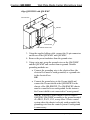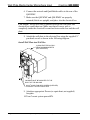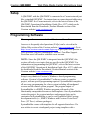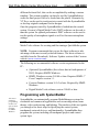
1
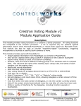
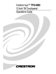
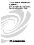
Crestron QM-WMIC Wall Plate Media Center Microphone Input Operations & Installation Guide This document was prepared and written by the Technical Documentation department at: Crestron Electronics, Inc. 15 Volvo Drive Rockleigh, NJ 07647 1-888-CRESTRON All brand names, product names and trademarks are the property of their respective owners. ©2003 Crestron Electronics, Inc. Crestron QM-WMIC Wall Plate Media Center Microphone Input Contents Wall Plate Media Center Microphone Input: QM-WMIC 1 Introduction......................................................................................1 Features and Functions ..........................................................1 Specifications.........................................................................3 Physical Description ..............................................................5 Industry Compliance..............................................................7 Installation........................................................................................8 Setup...............................................................................................11 Programming Software ..................................................................11 Programming with Crestron SystemBuilder...........................12 Programming with SIMPL Windows..................................13 Programming with VisionTools Pro-e.................................17 Example Program ................................................................17 Adjusting the QM-WMIC..............................................................18 Definitions ...........................................................................18 Setting Microphone Gain.....................................................20 Setting the Gating Level ......................................................20 Problem Solving.............................................................................22 Troubleshooting...................................................................22 Further Inquiries ..................................................................24 Future Updates.....................................................................24 Return and Warranty Policies ........................................................25 Merchandise Returns / Repair Service ................................25 CRESTRON Limited Warranty ..........................................25 Operations & Installation Guide - DOC. 6245 Contents • i Crestron QM-WMIC Wall Plate Media Center Microphone Input Wall Plate Media Center Microphone Input: QM-WMIC Introduction Features and Functions The Wall Plate Media Center Microphone Input (QM-WMIC) is an optional part of the Crestron MediaManager™ line of network devices, room control systems, and signal routing solutions. The QM-WMIC is a complementary accessory that can only be used when installed with a Crestron® QM-WMC Wall Plate Media Center. The QM-WMIC adds two Neutrik® Combo microphone connectors with software enabled phantom power to the A/V connections that are present on the QM-WMC. The microphone inputs feature adjustable gain and an integrated noise gate with adjustments for gating level, attack time, and decay time. The microphone signals are transmitted with the program audio over the Crestron QuickMedia transport. A QM-WMIC requires a QM-WMC, the far-right space in a 2½” deep, triple-gang electrical box and a Decora® style faceplate (sold by other) for installation. Functional Summary • 3-gang Decora style (requires installation with QM-WMC) • Two Neutrik Combo microphone connectors with muting and software switchable phantom power (48V @ 10mA) for condenser microphones • Adjustable gain, noise gate levels, attack time, and decay time Operations & Installation Guide - DOC. 6245 Wall Plate Media Center Microphone Input: QM-WMIC • 1 Wall Plate Media Center Microphone Input Crestron QM-WMIC The following block diagram illustrates the functional capabilities of a QM-WMC with the QM-WMIC installed. Block Diagram of Wall Plate Media Center Microphone Input 2 • Wall Plate Media Center Microphone Input: QM-WMIC Operations & Installation Guide - DOC. 6245 Crestron QM-WMIC Wall Plate Media Center Microphone Input Specifications The following table provides specifications for the QM-WMIC. Specifications for the QM-WMIC SPECIFICATION DETAILS Power Requirements Total QM-WMC & QM-WMIC Control System Update Files1,2 2-Series Control System 3 Watts (0.13 Amp @ 24 VDC) 8 Watts (0.33 Amp @ 24 VDC) Version 3.093.CUZ or later Front Connectors Mic Inputs (2) Neutrik Combo: XLR & ¼” phone per input Rear Connectors QM-WMC Microphone XLR Concentric ¼” Input Level Range XLR ¼” (1) Multi-pin ribbon connector for connecting to QM-WMC Accepts microphones with 60 Ohm to 600 Ohm output impedance, balanced Accepts line level inputs, balanced (tip/ring/sleeve) or unbalanced (tip/sleeve) -60 dBV to –20 dBV -28 dBV to +12 dBV balanced (-30 dBu to +10 dBu) -28 dBV to +6 dBV unbalanced (-30 dBu to +4 dBu) Max. Input: 4 Vrms balanced 2 Vrms unbalanced (continued on next page) Operations & Installation Guide - DOC. 6245 Wall Plate Media Center Microphone Input: QM-WMIC • 3 Wall Plate Media Center Microphone Input Crestron QM-WMIC Specifications for QM-WMIC (continued) SPECIFICATION Microphone (continued) Input Impedance Level Monitoring Noise Gate Phantom Power (XLR only) Voltage Current Source Impedance Operating Temperature and Humidity Dimensions and Weight DETAILS XLR: 10 kΩ ¼”: 4 kΩ balanced 2 kΩ unbalanced Provided for setup purposes. Nominal indication at 20 dB below input clip level. Clip indication reported at 6 dB below input clip level. Software enabled noise gating with adjustable level, attack time, and decay time (variable from 10 ms to 5 seconds). Software enabled3 48 V 10 mA (combined total) 3.4 kΩ 41º to 104º F (5º to 40º C) 10 to 90% relative humidity (non-condensing) Width: 1.77 in (4.49 cm) Height: 4.11 in (10.44 cm) Depth: 2.14 in (5.43 cm) Weight: 4.1 oz (0.12 kg) 1. The latest software versions can be obtained from the Downloads | Software Updates section of the Crestron website (www.crestron.com). Refer to the NOTE following these footnotes. 2. Crestron 2-Series control systems include the AV2, C2N-DVP4DI, CP2, CP2E, MC2E, MC2W, MP2, MP2E, PAC2, PRO2, QM-RMCRX, and RACK2. 3. Phantom power is applied to the XLR connectors of both microphone inputs. It cannot be enabled on an individual microphone input. NOTE: Crestron software and any files on the website are for Authorized Crestron dealers and Crestron Authorized Independent Programmers (CAIP) only. New users may be required to register to obtain access to certain areas of the site (including the FTP site). 4 • Wall Plate Media Center Microphone Input: QM-WMIC Operations & Installation Guide - DOC. 6245 Crestron QM-WMIC Wall Plate Media Center Microphone Input Physical Description The QM-WMIC features two Neutrik Combo XLR/¼” ports that allow for connection of up to two microphones. The XLR microphone connectors feature software switchable phantom power for use with condenser microphones. Microphone signals are transmitted along with the program audio and can be manipulated at the receiver. NOTE: Phantom power is applied to the XLR connectors of both microphone inputs. It cannot be switched on an individual microphone input. An LED on the front of the QM-WMIC indicates whether phantom power is enabled. The following illustration shows the QM-WMIC properly installed with a QM-WMC. NOTE: Decorative faceplates, as shown in the following illustrations, are not supplied. QM-WMIC Shown with QM-WMC Operations & Installation Guide - DOC. 6245 Wall Plate Media Center Microphone Input: QM-WMIC • 5 Wall Plate Media Center Microphone Input Crestron QM-WMIC Physical Views of the QM-WMIC Wall Plate Media Center 2.14 in (5.43 cm) 1.77 in (4.49 cm) 1.63 in (4.14 cm) 1.79 in (4.54 cm) 2.71 in (6.89 cm) 4.11 in (10.44 cm) All microphone connections to the QM-WMIC are made through the connectors on the front panel. An LED on the front of the QM-WMIC indicates when phantom power is on. The connection to the QM-WMC is made on the rear of the unit. Refer to the illustrations and descriptions that follow. 6 • Wall Plate Media Center Microphone Input: QM-WMIC Operations & Installation Guide - DOC. 6245 Crestron QM-WMIC Wall Plate Media Center Microphone Input NOTE: A ribbon cable for connecting to a QM-WMC is provided with the QM-WMIC. NOTE: Images shown are for illustrative purposes only. MIC 1 / MIC 2 Each MIC port is a Neutrik Combo connector that contains an XLR connector for use balanced condenser or dynamic microphones. The XLR connectors feature switchable phantom power. The ¼” phone connector is for use with devices that provide line-level signals such as wireless microphone receivers or the output of a microphone mixer. For more information on the microphone input capabilities, refer to the “Specifications” section on page 3. NOTE: Phantom power is not applied to the ¼” inputs. Phantom Power Indicator The QM-WMIC has an LED that illuminates when phantom power is enabled on the XLR connectors. Connection for QM-WMC (not labeled) This 14-pin connector is used to connect the QM-WMIC to the QM-WMC. Industry Compliance As of the date of manufacture, the QM-WMIC has been tested and found to comply with specifications for CE marking and standards per EMC and Radiocommunications Compliance Labelling (N11785). NOTE: This device complies with part 15 of the FCC rules. Operation is subject to the following two conditions: (1) this device may not cause harmful interference, and (2) this device must accept any interference received, including interference that may cause undesired operation. Operations & Installation Guide - DOC. 6245 Wall Plate Media Center Microphone Input: QM-WMIC • 7 Wall Plate Media Center Microphone Input Crestron QM-WMIC Installation The QM-WMIC is designed to connect to a dedicated connector on the rear of the QM-WMC Wall Plate Media Center. The following tools/hardware are required for installation. • Wire nut (not supplied) • Phillips screwdriver (not supplied) • Two ¾” pan head Phillips screws (supplied) NOTE: The QM-WMIC can be installed when the QM-WMC is being installed or after the QM-WMC has been installed. The following procedure is written for a scenario where the QM-WMIC is being installed at the same time as a QM-WMC. Detailed installation instructions for the QM-WMC can be found in the latest revision of the QM-WMC Operations & Installation Guide (Doc. 6237) which can be downloaded from the Downloads | Product Manuals section of the Crestron website (www.crestron.com). NOTE: If the QM-WMIC is to be installed into an existing QM-WMC installation, all electronic connections to the QM-WMC should be removed prior to removing the QM-WMC from its two-gang electrical wallbox. A three-gang box must replace the two-gang electrical wallbox. 1. Turn Cresnet system power OFF. 2. Place the QM-WMIC next to the QM-WMC as shown in the following diagram. 8 • Wall Plate Media Center Microphone Input: QM-WMIC Operations & Installation Guide - DOC. 6245 Crestron QM-WMIC Wall Plate Media Center Microphone Input Align QM-WMIC with QM-WMC GROUND WIRE QM-WMC GROUND WIRE QM-WMIC 14-PIN RIBBON CONNECTORS 3. Using the supplied ribbon cable, connect the 14-pin connectors on the rear of the QM-WMIC and QM-WMC. 4. Remove the precut insulation from the ground wires. 5. Using a wire nut, group the ground wires on the QM-WMIC and the QM-WMC and connect them to ground. Suitable grounding methods are: • Connect the grounding wire to the electrical box (the electrical box must be earth grounded) or a ground wire in the electrical box. OR • Connect the ground wires to the Cresnet shield and connect the Cresnet shield at the QM-RMCRX to the chassis of the QM-RMCRX. The QM-RMCRX chassis must be connected to an earth ground. In this instance, the Cresnet shield is not connected to Cresnet ground. NOTE: When the Cresnet shield is used to connect QM-WMC/QM-WMIC assembly to the ground terminal of a PRO2, PAC2, AV2, or any other 2-Series control system where the chassis is already earth grounded, the grounding wire from the control system to earth ground is unnecessary. Operations & Installation Guide - DOC. 6245 Wall Plate Media Center Microphone Input: QM-WMIC • 9 Wall Plate Media Center Microphone Input Crestron QM-WMIC 6. Connect the network and QuickMedia cables to the rear of the QM-WMC. 7. Make sure the QM-WMC and QM-WMIC are properly oriented (labels are upright), and place it in the electrical box. CAUTION: Excess wire that is pinched between the wall plate and electrical box could short out. Make sure that all excess wire is completely inside the electrical box and not between the box and the wall plate. 8. Attach the wall plate to the electrical box using the supplied ¾” pan-head screws as shown in the following diagram. Install Wall Plate into Wall Box 3-GANG ELECTRICAL BOX 212 INCH MINIMUM DEPTH (NOT SUPPLIED) QM-WMIC MUST BE MOUNTED TO THE RIGHT OF THE QM-WMC 6-32 X 3 4 INCH PAN HEAD SCREW (SUPPLIED) TO MOUNT TO ELECTRICAL BOX 9. Attach an appropriate Decora (or equivalent, not supplied) faceplate. 10. Turn Cresnet system power ON. 10 • Wall Plate Media Center Microphone Input: QM-WMIC Operations & Installation Guide - DOC. 6245 Crestron QM-WMIC Wall Plate Media Center Microphone Input Setup A QM-WMC with the QM-WMIC is connected to a Cresnet network just like a standard QM-WMC. For instructions on connecting and addressing the QM-WMC in a Cresnet network, refer to the latest revision of the QM-WMC Operations & Installation Guide (Doc. 6237) which can be downloaded from the Downloads | Product Manuals section of the Crestron website (www.crestron.com). Programming Software Have a question or comment about Crestron software? Answers to frequently asked questions (FAQs) can be viewed in the Online Help section of the Crestron website (www.crestron.com). Go to http://www.crestron.com/accounts/login.asp to post your own question or view questions you have submitted to Crestron’s True Blue Support. First-time users will need to establish a user account. NOTE: Since the QM-WMIC is integrated into the QM-WMC, this section will only cover topics that are specific to the QM-WMIC. For information on programming the QM-WMC, refer to the latest revision of the QM-WMC Operations & Installation Guide (Doc. 6237) which can be downloaded from the Downloads | Product Manuals section of the Crestron website (www.crestron.com). Setup is easy thanks to Crestron’s Windows-based programming software. Crestron’s SystemBuilder™ software creates a complete project, with no special programming required. SystemBuilder completes all necessary programming for a base system including all touchpanel screens and the control system program. The program output of SystemBuilder is a SIMPL Windows program with much of the functionality encapsulated in macros and templates. Once SystemBuilder creates the project, the system interfaces and program logic can be customized in SystemBuilder or can be easily modified with Crestron development tools (i.e., SIMPL Windows and Crestron VisionTools® Pro-e (VT Pro-e) software packages). SystemBuilder comes with templates for all supported interfaces. If a user wishes to create a touchpanel project using templates with a Operations & Installation Guide - DOC. 6245 Wall Plate Media Center Microphone Input: QM-WMIC • 11 Wall Plate Media Center Microphone Input Crestron QM-WMIC different look-and-feel, this can be accomplished by making a custom template. This custom template can then be used by SystemBuilder to create the final project files to be loaded into the panels. Alternatively, VT Pro-e can be used to tweak projects created with the SystemBuilder or develop original touchpanel screen designs. Once the program created by SystemBuilder is loaded into the control system, Crestron’s Digital Media Tools (DMT) software can be used to tune the system for optimal performance. DMT software can be used to test the quality of microphone signals as well as fine-tune microphone settings. NOTE: Crestron recommends the use of SystemBuilder and Digital Media Tools software for creating and fine-tuning a QuickMedia system. NOTE: Crestron recommends that you use the latest software to take advantage of the most recently released features. The latest software is available from the Downloads | Software Updates section of the Crestron website (www.crestron.com). The following are recommended software version requirements for the PC: • (Optional) SystemBuilder (first release due in fourth quarter of 2003). Requires SIMPL Windows. • SIMPL Windows version 2.05.08 or later. Requires SIMPL+® Cross Compiler version 1.1. • Crestron Database version 16.0.5 or later. Required by SIMPL Windows. • Digital Media Tools software version 3.00.00 or later. Programming with SystemBuilder The easiest method of programming, but does not offer as much flexibility as SIMPL Windows. SystemBuilder can automatically program MediaManager systems for residential and commercial applications such as meeting rooms, home theater, video conferencing, and lighting. The interface of this tool guides you through a few basic steps for specifying the control system, touchpanels, network devices, and functionality. SystemBuilder then programs the system, including all touchpanel projects and control system logic. 12 • Wall Plate Media Center Microphone Input: QM-WMIC Operations & Installation Guide - DOC. 6245 Crestron QM-WMIC Wall Plate Media Center Microphone Input Selection of QM-WMC and QM-WMIC in SystemBuilder SystemBuilder integrates fully with Crestron’s suite of software development tools, including SIMPL Windows, VT Pro-e, and the Crestron Database. SystemBuilder accesses these tools behind the scenes, enabling you to easily create robust systems. Programming with SIMPL Windows The QM-WMC device in SIMPL Windows contains the symbols for the QM-WMC and the QM-WMIC. For instructions on adding a QM-WMC to a SIMPL Windows program, refer to the latest revision of the QM-WMC Operations & Installation Guide (Doc. 6237) which can be downloaded from the Downloads | Product Manuals section of the Crestron website (www.crestron.com). NOTE: While SIMPL Windows can be used to program the QM-WMIC, it is recommended to use SystemBuilder and Digital Media Tools software for configuring and tuning a QuickMedia system. NOTE: The following assumes that the reader has knowledge of SIMPL Windows. If not, refer to the extensive help information provided with the software. Operations & Installation Guide - DOC. 6245 Wall Plate Media Center Microphone Input: QM-WMIC • 13 Wall Plate Media Center Microphone Input Crestron QM-WMIC Locating the QM-WMIC Symbol The QM-WMIC symbol is in Slot 2 of the QM-WMC symbol. Doubleclick Slot 2 of the QM-WMC symbol to view the details of the QM-WMIC symbol. QM-WMIC Symbol in Programming Manager Programming Manager is where programmers “program” a Crestron control system by assigning signals to symbols. The following describes the QM-WMIC symbol in the SIMPL Windows Programming Manager. NOTE: Many of the signals in the QM-WMIC symbol are used to adjust operating parameters such as gain, gating/gating level, attack time and decay time. For definitions and information on the effects of adjusting these parameters, refer to “Adjusting the QM-WMIC” on page 18. QM-WMIC symbol in SIMPL Windows Programming Manager The following tables list the symbol’s input and output signals, respectively, and their functional descriptions. 14 • Wall Plate Media Center Microphone Input: QM-WMIC Operations & Installation Guide - DOC. 6245 Crestron QM-WMIC Wall Plate Media Center Microphone Input QM-WMIC Digital Input Signal Descriptions INPUT DESCRIPTION Mic1Mute Mutes the input signal from Mic 1 when high Mic2Mute Mic1GatingEnable Mic2GatingEnable PhantomEnable Mutes the input signal from Mic 2 when high Enables automatic gating on Mic 1 when high Enables automatic gating on Mic 2 when high Enables phantom power for both microphone inputs when high NOTE: Phantom power is applied to the XLR connectors of both microphone inputs. It cannot be switched on an individual microphone input. QM-WMIC Analog Input Signal Descriptions INPUT Mic1GatingLevel Mic2GatingLevel Mic1Gain Mic2Gain AttackTime DecayTime DESCRIPTION Specifies gating level for Mic 1 (0 to 100%) Specifies gating level for Mic 2 (0 to 100%) Specifies gain level for Mic 1 (0 to 100%) Specifies gain level for Mic 2 (0 to 100%) Specifies attack time (10 to 100 ms) Specifies decay time (10 to 5000 ms) NOTE: AttackTime and DecayTime are applied to both microphone inputs. QM-WMIC Digital Output Signal Descriptions OUTPUT DESCRIPTION Mic1Mute-F Indicates Mic 1 is muted Mic2Mute-F Mic1GatingEnable-F Mic2GatingEnable-F Mic1Gate Mic1Nominal Indicates Mic 2 is muted Indicates automatic gating on Mic 1 enabled Indicates automatic gating on Mic 2 enabled Indicates Mic 1 gating level has been reached Indicates Mic 1 at nominal level (continued on next page) Operations & Installation Guide - DOC. 6245 Wall Plate Media Center Microphone Input: QM-WMIC • 15 Wall Plate Media Center Microphone Input Crestron QM-WMIC QM-WMIC Digital Output Signal Descriptions (continued) OUTPUT Mic1Clip Mic2Gate Mic2Nominal Mic2Clip PhantomEnable-F DESCRIPTION Indicates Mic 1 signal is at 6 dB below input clip level Indicates Mic 2 gating level has been reached Indicates Mic 2 at nominal level Indicates Mic 2 signal is at 6 dB below input clip level Indicates when phantom power is enabled. NOTE: The gating level indicators will still function even if the gating function is not enabled. NOTE: Nominal indication is reported at 20 dB below input clip level. Clip indication is reported at 6 dB below input clip level. QM-WMIC Analog Output Signal Descriptions OUTPUT Mic1GatingLevel-F Mic2GatingLevel-F Mic1Gain-F Mic2Gain-F AttackTime-F DecayTime-F DESCRIPTION Gating level feedback for Mic 1 Gating level feedback for Mic 2 Gain level feedback for Mic 1 Gain level feedback for Mic 2 Attack time setting feedback Decay time setting feedback NOTE: Returned values match values that were selected for the GatingLevel, Gain, AttackTime and DecayTime inputs. 16 • Wall Plate Media Center Microphone Input: QM-WMIC Operations & Installation Guide - DOC. 6245 Crestron QM-WMIC Wall Plate Media Center Microphone Input Programming with VisionTools Pro-e Touchpanel screens can be created in VT Pro-e to allow configuration of phantom power, gain levels, gating levels, attack times, and decay times. Digital Media Tools software already has these controls built in. Refer to the section “Adjusting the QM-WMIC” on page 18 for instructions. Example Program An example program for the wall plate is available from the Crestron FTP site (ftp://ftp.crestron.com/Examples). Search for the file named QM-WMC_QM-WMIC.ZIP. Operations & Installation Guide - DOC. 6245 Wall Plate Media Center Microphone Input: QM-WMIC • 17 Wall Plate Media Center Microphone Input Crestron QM-WMIC Adjusting the QM-WMIC Once a QM-WMIC is installed and configured, settings for gain, gating level, attack time, and decay time must be set using the Realtime Mode in Digital Media Tools (version 3.00.00 or later). Digital Media Tools software can be started from the SystemBuilder application. NOTE: Crestron recommends that you use the latest software to take advantage of the most recently released features. The latest software is available from the Downloads | Software Updates section of the Crestron website (www.crestron.com). Definitions The QM-WMIC allows for adjustments to be made to microphone input signals. Following are definitions of terms that are commonly used when making adjustments to the QM-WMIC. Attack Time The time it takes (in milliseconds) from when an input signal rises above the gating level until the microphone output signal is enabled. Clipping A condition in which a signal level exceeds the maximum level (the clipping level) a circuit can handle. This is usually caused by improper gating parameters and gain settings. Decay Time The time (in milliseconds) from when an input signal falls below the gating level until the microphone output signal is muted. Gain An adjustable amplification to accommodate varying input signal levels. Gating A function that mutes a microphone signal when the input sound level is below a user-set threshold (Gating Level). The following diagram demonstrates Clipping, Attack Time, Decay Time, and Gating level. 18 • Wall Plate Media Center Microphone Input: QM-WMIC Operations & Installation Guide - DOC. 6245 Crestron QM-WMIC Wall Plate Media Center Microphone Input Visual Representation of Gating Level, Clipping Level, Attack Time, and Decay Time SIGNAL LEVEL MICROPHONE INPUT SIGNAL Clipping Level Mic On Gating Level Mic Off TIME Decay Time Attack Time SIGNAL LEVEL QM OUTPUT SIGNAL Gating Level Reached Gating Level Reached Mic On Mic Off TIME Attack Time Operations & Installation Guide - DOC. 6245 Decay Time Wall Plate Media Center Microphone Input: QM-WMIC • 19 Wall Plate Media Center Microphone Input Crestron QM-WMIC Setting Microphone Gain The QM-WMIC provides variable gain on the XLR and ¼” microphone inputs. The following procedure is used to set the optimal gain for a microphone input. Use the Realtime Mode in Digital Media Tools to control phantom power, gain and gate settings, and to monitor the gate, normal, and clip level indicators. For information on using Digital Media Tools software, refer to the extensive help information provided with the software. NOTE: The input gain is independent of the system’s output volume level. 1. To adjust the input gain, set the gain and noise gate to their lowest settings. Disable the “Mute” function by removing the check from the Mute checkbox. 2. Connect a microphone and enable phantom power if required. 3. Increase the gain while providing a “normal” sound level input to the microphone. When the “Norm” indicator shows fairly consistent activity, you’ve reached a good signal level for the QM-WMIC. NOTE: The "clip" indicator shows that the signal is clipping. Let your ears be the judge, but when the clip indicator is active, you are approaching or have reached distortion in your QM-WMIC signal. Occasional clip indications on loud input are expected, but constant clip indicator activity is a sign that the gain may be set too high. 4. Set the system output volume to a desirable listening level and verify the gain settings by listening to the system output. Some minor gain adjustment may be required for the “best sound” in any specific configuration. Setting the Gating Level The QM-WMIC provides an input level gating function that will mute a microphone signal when the input sound level is below a user-set threshold. This function can be enabled or disabled via software commands. 20 • Wall Plate Media Center Microphone Input: QM-WMIC Operations & Installation Guide - DOC. 6245 Crestron QM-WMIC Wall Plate Media Center Microphone Input Use the Realtime Mode in Digital Media Tools to control phantom power, gain and gate settings, and to monitor the gate, normal, and clip level indicators. For information on using Digital Media Tools software, refer to the extensive help information provided with the software. The following procedure sets the optimal “gate level” for the microphone inputs: 1. Follow the “Setting Microphone Gain” procedure on page 20 to set the gain for each microphone input. 2. Set the noise gate level, attack and decay times to minimum. Disable the “Mute” function by removing the check from the Mute checkbox. 3. While providing a level to the microphone that is equivalent to the background noise that should be gated out, increase the noise gate level until the Gated indicator turns off. When the input sound levels are at or below the established noise gate level, the microphone output signal will be gated off. 4. Set the “attack time” to the minimum level and the “decay time” to the maximum level. These settings provide the shortest time to enable the microphone output when an input is above the gating level, and the longest time before disabling the microphone after such an input. NOTE: The “attack” and “decay times” are applied to both microphone inputs. 5. Set the system output volume to a desirable listening level. While providing realistic voice input and background noise levels, adjust the gating level and attack/decay times to eliminate undesired input while providing the best content quality. Operations & Installation Guide - DOC. 6245 Wall Plate Media Center Microphone Input: QM-WMIC • 21 Wall Plate Media Center Microphone Input Crestron QM-WMIC Problem Solving Troubleshooting The table below provides corrective action for possible trouble situations. If further assistance is required, please contact a Crestron customer service representative. QM-WMIC Media Center Microphone Input Troubleshooting TROUBLE QM-WMIC is not functioning. POSSIBLE CAUSE(S) CORRECTIVE ACTION QM-WMIC is not receiving power. QM-WMC Net ID is not correct. Microphone does not produce sound. QM-WMC Net ID is not set to match the Net ID specified in SIMPL Windows. QM-WMC Net ID is the same as another device’s Net ID. Microphone requires phantom power or cannot use phantom power. Incorrect gain, gating level, attack time or decay time settings. Check wiring connections to QM-WMC and QM-WMIC. In Viewport, poll the network to verify the Net ID of the QM-WMC. Verify SIMPL Windows program for setting Net ID. Assign a different Net ID for the QM-WMC to match the Net ID specified in the SIMPL Windows program. Enable or disable phantom power as necessary using controls created in the SystemBuilder project. Adjust gain, gating level, attack time, or decay time settings as required. (continued on next page) 22 • Wall Plate Media Center Microphone Input: QM-WMIC Operations & Installation Guide - DOC. 6245 Crestron QM-WMIC Wall Plate Media Center Microphone Input QM-WMIC Media Center Microphone Input Troubleshooting (continued) TROUBLE Microphone does not produce sound. Intermittent microphone output. Microphone produces harsh, distorted sound. “Hum” in microphone audio. Operations & Installation Guide - DOC. 6245 POSSIBLE CAUSE(S) Incorrect volume and/or mixer settings on QM-RMCRX. Incorrect peak setting. CORRECTIVE ACTION Adjust volume and/or mixer settings on QM-RMCRX as required. Poor cable connection. Input gain is set too high. Adjust QM-RMCRX peak control until audio is restored. For more information refer to the latest revision of the QM-RMCRX Operations and Installation Guide (Doc. 6236). Verify all cable connections. Lower microphone input gain. QM device is improperly grounded. Ensure that all devices in the system are properly grounded. Wall Plate Media Center Microphone Input: QM-WMIC • 23 Wall Plate Media Center Microphone Input Crestron QM-WMIC Further Inquiries If, after reviewing this Operations and Installation Guide for the wall plates, you cannot locate specific information or have questions, please take advantage of Crestron's award winning customer service team in your area. Dial one of the following numbers. • In the US and Canada, call Crestron's corporate headquarters at 1-888-CRESTRON [1-888-273-7876]. • In Europe, call Crestron International at +32-15-50-99-50. • In Asia, call Crestron Asia at +852-2341-2016. • In Latin America, call Crestron Latin America at +5255-5093-2160. • In Australia and New Zealand, call Crestron Control Solutions at +61-2-9737-8203. You can also log onto the online help section of the Crestron website (www.crestron.com) to ask questions about Crestron products. First-time users will need to establish a user account to fully benefit from all available features. Future Updates As Crestron improves functions, adds new features, and extends the capabilities of the QM-WMIC, additional information may be made available as manual updates. These updates are solely electronic and serve as intermediary supplements prior to the release of a complete technical documentation revision. Check the Crestron website (www.crestron.com) periodically for manual update availability and its relevance. Updates are available from the Downloads | Product Manuals section and are identified as an “Addendum” in the Download column. 24 • Wall Plate Media Center Microphone Input: QM-WMIC Operations & Installation Guide - DOC. 6245 Crestron QM-WMIC Wall Plate Media Center Microphone Input Return and Warranty Policies Merchandise Returns / Repair Service 1. No merchandise may be returned for credit, exchange, or service without prior authorization from CRESTRON. To obtain warranty service for CRESTRON products, contact the factory and request an RMA (Return Merchandise Authorization) number. Enclose a note specifying the nature of the problem, name and phone number of contact person, RMA number, and return address. 2. Products may be returned for credit, exchange, or service with a CRESTRON Return Merchandise Authorization (RMA) number. Authorized returns must be shipped freight prepaid to CRESTRON, 6 Volvo Drive, Rockleigh, N.J., or its authorized subsidiaries, with RMA number clearly marked on the outside of all cartons. Shipments arriving freight collect or without an RMA number shall be subject to refusal. CRESTRON reserves the right in its sole and absolute discretion to charge a 15% restocking fee, plus shipping costs, on any products returned with an RMA. 3. Return freight charges following repair of items under warranty shall be paid by CRESTRON, shipping by standard ground carrier. In the event repairs are found to be non-warranty, return freight costs shall be paid by the purchaser. CRESTRON Limited Warranty CRESTRON ELECTRONICS, Inc. warrants its products to be free from manufacturing defects in materials and workmanship under normal use for a period of three (3) years from the date of purchase from CRESTRON, with the following exceptions: disk drives and any other moving or rotating mechanical parts, pan/tilt heads and power supplies are covered for a period of one (1) year; touchscreen display and overlay components are covered for 90 days; batteries and incandescent lamps are not covered. This warranty extends to products purchased directly from CRESTRON or an authorized CRESTRON dealer. Purchasers should inquire of the dealer regarding the nature and extent of the dealer's warranty, if any. CRESTRON shall not be liable to honor the terms of this warranty if the product has been used in any application other than that for which it was intended, or if it has been subjected to misuse, accidental damage, modification, or improper installation procedures. Furthermore, this warranty does not cover any product that has had the serial number altered, defaced, or removed. This warranty shall be the sole and exclusive remedy to the original purchaser. In no event shall CRESTRON be liable for incidental or consequential damages of any kind (property or economic damages inclusive) arising from the sale or use of this equipment. CRESTRON is not liable for any claim made by a third party or made by the purchaser for a third party. CRESTRON shall, at its option, repair or replace any product found defective, without charge for parts or labor. Repaired or replaced equipment and parts supplied under this warranty shall be covered only by the unexpired portion of the warranty. Except as expressly set forth in this warranty, CRESTRON makes no other warranties, expressed or implied, nor authorizes any other party to offer any warranty, including any implied warranties of merchantability or fitness for a particular purpose. Any implied warranties that may be imposed by law are limited to the terms of this limited warranty. This warranty statement supercedes all previous warranties. Trademark Information All brand names, product names, and trademarks are the sole property of their respective owners. Windows is a registered trademark of Microsoft Corporation. Windows95/98/Me/XP and WindowsNT/2000 are trademarks of Microsoft Corporation. Operations & Installation Guide - DOC. 6245 Wall Plate Media Center Microphone Input: QM-WMIC • 25 Wall Plate Media Center Microphone Input Crestron QM-WMIC This page is intentionally left blank. 26 • Wall Plate Media Center Microphone Input: QM-WMIC Operations & Installation Guide - DOC. 6245 Crestron QM-WMIC Wall Plate Media Center Microphone Input This page is intentionally left blank. Operations & Installation Guide - DOC. 6245 Wall Plate Media Center Microphone Input: QM-WMIC • 27 Crestron Electronics, Inc. 15 Volvo Drive Rockleigh, NJ 07647 Tel: 888.CRESTRON Fax: 201.767.7576 www.crestron.com Operations & Installation Guide - DOC. 6245 12.03 Specifications subject to change without notice.