1
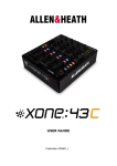
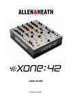
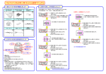
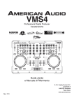
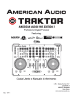
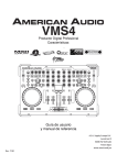
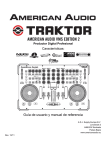
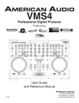
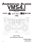
USER GUIDE
Publication AP9433_1
1
Limited One Year Warranty
This product is warranted to be free from defects in materials or
workmanship for period of one year from the date of purchase by the
original owner.
To ensure a high level of performance and reliability for which this
equipment has been designed and manufactured, read this User Guide
before operating. In the event of a failure, notify and return the
defective unit to ALLEN & HEATH Limited or its authorised agent as
soon as possible for repair under warranty subject to the following
conditions
Conditions Of Warranty
The equipment has been installed and operated in accordance with the
instructions in this User Guide.
The equipment has not been subject to misuse either intended or
accidental, neglect, or alteration other than as described in the User
Guide or Service Manual, or approved by ALLEN & HEATH.
Any necessary adjustment, alteration or repair has been carried out by
ALLEN & HEATH or its authorised agent.
This warranty does not cover fader wear and tear.
The defective unit is to be returned carriage prepaid to ALLEN &
HEATH or its authorised agent with proof of purchase.
Units returned should be packed to avoid transit damage.
In certain territories the terms may vary. Check with your ALLEN &
HEATH agent for any additional warranty which may apply.
This product complies with the European Electromagnetic
Compatibility directives 2004/108/EC and the European Low Voltage
directives 2006/95/EC.
Any changes or modifications to the equipment not approved by Allen &
Heath could void the compliance of the product and therefore the users
authority to operate it.
XONE:23C User Guide AP9433 Issue 1
Copyright © 2014 Allen & Heath Limited. All rights reserved
Allen & Heath Limited
Kernick Industrial Estate, Penryn, Cornwall, TR10 9LU, UK
http://www.allen-heath.com http//www.xone.co.uk
2
PACKED ITEMS
Check that you have received the following:
Xone:23C mixer
Power Supply
12V - 2.5 Amps
Type A-B USB Lead
To connect the Xone:23C
to your computer.
Power supply IEC Lead
This is country specific and will
vary with mains voltage/territory
Two 17cm, three-way harnesses.
These are to configure the
soundcard for DVS - see page 19
Safety Sheet
Important ! Read this sheet
before starting.
Retain for future reference.
MixVibes Software Voucher
This contains the license
number that allows you to
download and use Mixvibes
with your Xone:23C
3
CONTENTS
Congratulations on purchasing the Allen & Heath Xone:23C performance
DJ mixer. To ensure that you get the maximum benefit from the unit
please spare a few minutes familiarizing yourself with the controls and
setup procedures outlined in this user guide. For further information
please refer to the additional information available on our web site, or
contact our technical support team.
http://www.xone.co.uk
http://www.allen-heath.com
Warranty ........................................................
Packed Items ..................................................
Contents.........................................................
Connection diagram.....................................
Introduction ...................................................
Input channel controls .................................
Master section controls ..............................
Mic and Filter controls ................................
Rear panel connections ...............................
Driver installation Mac ................................
Driver installation PC ..................................
Filters reference ............................................
Operating levels ............................................
Earthing ...........................................................
Servicing ........................................................
Reconfiguring the soundcard for DVS ......
User replaceable spare parts......................
Tips and fault finding ....................................
Specification ...................................................
Block Diagram ...............................................
Product registration .....................................
2
3
4
5
6
7
8
9
10
11
13
15
16
17
18
19
20
21
22
23
25
4
APPLICATION DIAGRAM
5
INTRODUCTION TO THE XONE:23C
The Xone:23C is a high performance 2+2 channel VCA mixer designed
around the latest analogue circuitry, with microprocessor control of all
signal routing and featuring a high specification USB soundcard, incorporating
an X:LINK control interface port.
It is equipped with a version of the classic Xone filter system, a 3 band “Kill
Type” EQ Isolator, plus a send/return loop for external effects.
The crossfader curve has two settings, suitable for beat matching, or a more
aggressive curve for scratching. For ultimate crossfader performance the
mixer can also be equipped with a custom Innofader, available from your
nearest Allen & Heath stockist, (part number 004-504JIT).
With a studio grade 20dB of signal headroom, a separate booth monitor and
balanced XLR main outputs, (with an impressive +28dBu max level) the
Xone:23C is ideal for the DJ who requires a high quality compact mix tool
that easily interfaces with all leading DJ software.
Some key features of the Xone:23C:
•
•
•
•
•
•
•
•
•
•
•
•
•
•
•
•
•
•
•
Four channel stereo 24bit/96kHz USB soundcard with X:LINK
Classic Xone Voltage Controlled Filter system
Up to four sources can be mixed simultaneously
Kill-type three Band, full cut equalizer
Dedicated booth Monitor
Outputs on professional standard balanced XLR connectors
Four inputs (2+2 stereo channels) with dual levels for phono/line inputs
FX Send/Return loop
Innofader crossfader option
Accurate signal level monitoring with peak hold
+28dBu maximum output level (balanced XLR)
High internal headroom (+20dB) to prevent overload
Universal voltage power supply (works anywhere in the World)
Twin headphone sockets (1/4” and 3.5mm)
Separate record output on RCA
Negligible signal distortion (typically 0.01% at +10dBu output)
UV sensitive ink screen for improved low light legibility
Cue-mix control with illuminated Cue switches
Crossfader curve switch
We wish you the same fun playing on it as we have had designing it!
http://www.xone.co.uk
http://www.allen-heath.com
6
INPUT CHANNEL CONTROLS
Input level controls
Adjust so the average
music level lights the 0
LED on the meter, with
the beats lighting the +3
to +6 LED. Turn down if
the +10 Red LED is illuminated. Each input has
its own separate level
control, so make sure to
fully
turn
down
(anticlockwise) the input
you don’t want feeding
into the channel.
3-Band full kill EQ
Turn anti-clockwise to
kill a frequency band or
clockwise to boost.
If all controls are fully anti
-clockwise the signal will
be muted
Filter/FX SND switch
Pressing this switch sends
the channel signal to the
VCF filter section, and
to the external effects
SND output
Channel Cue switch
Pressing this switch
allows you to monitor
the channel signal with
the fader fully down
before bringing it into the
mix.
Channel Fader
VCA fader allows you to progressively
raise or lower the channel signal in the
mix.
For best signal-to-noise ratio, mix with
the fader at or near the top of its travel
7
MASTER CONTROLS
Master output Level
Sets the signal level to the
main XLR mix output
Monitor output Level
Sets the signal level for the
local monitor (booth) output
Cue/Mix Control
When set to Cue, nothing will
be sent to the headphone
output unless a channel Cue is
activated. When set to Mix,
the main mix will always be
sent to the headphones. In the
centre position the Cue signal
and the main mix are summed
together.
Headphone level
Sets the level of the headphone output.
Warning! Very high level can
cause hearing damage!
Headphone Sockets
Twin sockets for both 1/4”
and 3.5mm plugs. Use a good
quality set with an impedance
between 25 - 70 Ohms.
Crossfader
Crossfader curve switch
This is used to “fade” the signal level between
the two channels, and its response is set using the curve switch. When the crossfader is
fully over to the left only the music from
channel 1 will be heard, and when fully to the
right only channel 2. When in the centre the
music from both channels will be heard in
equal proportion.
Push to the left for a progressive fader
response, useful for blending between
tracks. Push to the right for a sharper
response, more suitable for scratching
8
MIC AND FILTER CONTROLS
Microphone input
Professional XLR balanced mic
input. Use a low impedance
dynamic hypercardioid Mic for
best results.
Microphone Level
Adjusts the signal level of the
mic input. If you are not using
the mic, turn to minimum to
prevent noise pick up.
Microphone EQ
2 band EQ for adjusting the
tonal balance of the DJ mic
FX loop on switch
Press this switch to activate
the external effect loop. Leave
switched off if an external
effects unit is not connected
Filter Frequency
Filter Resonance control
Filter type select
Sets the cut off frequency of
the VCF filter
Changes the “Q” or sharpness
of the VCF.
HPF - allows signals above the
cut-off frequency to pass.
Mild will give a smooth filter
sound, Wild will make the
filter sound more pronounced
(sharper “Q”)
LPF - allows signals below the
cut-off frequency to pass
9
REAR PANEL CONNECTIONS
Line input
Phono inputs
Line input
For connection to
a line level device;
(CD players etc)
For connection to turntables only; this input has RIAA equalization for
moving magnet cartridges.
For connection to
a line level device;
(CD players etc)
Note: An internal modification can convert these to Line (see page 18)
Effects SND output
Effects RTN input
Connect this output
to the input of an external effects unit.
Connect this input to
the output of an
external effects unit.
P o w e r
Switch
Switches
the unit On/
Off
MADEINCHINA
USB and X:LINK
Monitor output
Grounding post
Connect USB to a computer to
stream audio files or to record
the output of the mixer into
software.
Connect to a powered
speaker or Hi-FI system
Connect the ground
wire from turntables
(if fitted) to minimise
hum
Connect the X:LINK socket
to any compatible Allen &
Heath controller to enable
MIDI data to be passed to the
computer.
PSU connection
To prevent damage to your
Xone:23 only use an A&H
approved power supply
Main outputs
Connect these to a PA
amplifier using professional
balanced XLR connectors
for maximum hum and
noise rejection.
Do not short either pins
2 or 3 to ground. For
unbalanced operation
use pin 2 only and leave
pin 3 floating.
Record output
Use to record your mix.
Connect to a Minidisk
recorder or computer
soundcard input etc
Failure to observe this
could result in damage
to your Xone:23C
10
Driver installation Mac
Drivers
Although the Xone:23C is class compliant and will work on a Mac without drivers, for best performance we
recommend you download the dedicated drivers from our website:
www.allen-heath.com/xone23cdrivers
When the drivers have downloaded, extract them to a folder and click on the .dmg file to start installation:
Click Install
Click Continue
Click Continue Installation
Enter your user name and password then click
install software
When the installation finishes, click continue
And restart your computer when prompted
Installation is complete and your computer will connect and recognise your Xone:23C as an audio and
MIDI device.
11
Driver installation Mac
Checking the Audio MIDI Setup
To confirm that the Xone:23C is properly installed or to configure the Audio or MIDI. With the mixer
switched on and connected to your computer, open the AUDIO MIDI utility - (to find this utility type
“Audio MIDI” into spotlight (the magnifier at the top left of the desktop) and follow the links.
The driver offers two modes of operation:
Bit Accurate and Core Audio.
Bit accurate - in this mode the Xone:23C controls the
audio clocks and provides the lowest latency and least
jitter. We recommend working in this mode for best
performance.
Core Audio - In this mode the driver is fully class complaint and will allow aggregation with other soundcards
connected to your computer, but will have slightly higher
latency and clock jitter.
Selecting either driver will bring up the devices properties and will allow you to configure the sample rate
and input/output routing. The sample rate can be set from 44.1kHz up to a maximum of 96kHz. If you
mostly play commercially available music files it is recommended that you set the sample rate to 44.1kHz as
this will save the replay software from have to perform sample rate conversation which can create low level
artefacts.
MIDI
You can confirm that the Xone:23C is also set as a MIDI
device by selecting MIDI Studio where the mixer’s icon will
be listed.
X:LINK
The Xone:23C does not send any MIDI on its own, however it is fitted with an A&H proprietary interface
called X:Link. This will allow you to connect an Allen & Heath controller (such as the Xone:K2) to the mixer which will both provide power to the device and pass MIDI up the USB connection.
12
Driver installation PC
Drivers
In order to access all the soundcard channels on your Xone:23C you will need to install the dedicated ASIO
driver, which can be downloaded from our website:
www.allen-heath.com/xone23cdrivers
When the drivers have downloaded, extract them to a folder and click on the setup file to start installation:
Choose your language and
click OK to continue
Click Install the driver
During the installation you will twice
be asked to unplug and re-plug the
USB audio cable to your Xone:23C
Restart your computer when prompted
Installation is complete and your computer will now connect and recognise your Xone:23C as an
audio and MIDI device.
13
Driver installation PC
Checking the Audio MIDI Setup
To confirm that the Xone:23C is properly installed open Windows Device Manager (click on the start
button, then right click “computer” and select “properties”, then select “Device Manager”)
The Xone:23C should be listed under
“Sound, video and game controllers” as
both an audio and MIDI device, and will also
be listed under USB controllers.
To check the driver version, double click the
Xone:23C WDM driver icon to bring up the
“properties” box.
Select the driver tab to see details of the driver version.
14
FILTER REFERENCE
The VCF Filters
A voltage controlled filter is an audio filter where the cut-off frequency is altered by a DC
control voltage rather than a variable resistor. This produces a much wider operating
range and more control over the filter response to create unlimited combinations of
tonal effect.
Filter Type Select
The filters provide two simultaneous filter types: high-pass, and low-pass.
illuminated switches select which type is active.
Large
The graphs below show the effect on the audio frequency response for the two filter
types. The range of sweep from low to high frequency is shown together with the effect
of adjusting RESONANCE.
The vertical scale shows the amount of cut or boost around the normal 0dB operating
level. The horizontal scale shows the change in frequency from low (bass) to high
(treble).
LO-PASS FILTER
+20
+15
+10
LO
+5
HI
0dB
-5
-10
-15
-20
20
100
1kHz
10k
20k
10k
20k
HI-PASS FILTER
+20
+15
+10
LO
+5
HI
0dB
-5
-10
-15
-20
20
100
1kHz
15
OPERATING LEVELS
It is most important that the system level settings are correctly set. It is well known that
many DJs push the level to maximum with meters peaking hard in the belief that they are
getting the best from the system. THIS IS NOT THE CASE ! The best can only be
achieved if the system levels are set within the normal operating range and not allowed to
peak. Peaking simply results in signal distortion, not more volume. It is the specification of
the amplifier / speaker system that sets the maximum volume that can be achieved, not the
console. The human ear too can fool the operator into believing that more volume is
needed. Be careful as this is in fact a warning that hearing damage will result if high
listening levels are maintained. Remember that it is the QUALITY of the sound that
pleases the ear, not just the VOLUME.
The diagram below illustrates the operating range of the audio signal.
NORMAL OPERATING RANGE. For normal music the signal should range between
–6 and +6 on the meters with average around 0dB. This allows enough HEADROOM for
unexpected peaks before the signal hits its maximum CLIPPING voltage and distorts.
It also achieves the best SIGNAL-TO-NOISE RATIO by keeping the signal well above
the residual NOISE FLOOR (system hiss).
The DYNAMIC RANGE is the maximum signal swing available between the residual
noise floor and clipping.
82!
An important note …
The human ear is a remarkable organ with the ability to compress or ‘shut down’ when sound levels become too high. Do
not interpret this natural response as a reason to turn the system volume up further! As the session wears on ear fatigue
may set in, and the speaker cones may become hot, increasing
distortion and reducing the ability of listeners to gain any benefit from increased volume.
16
EARTHING
The connection to earth (ground) in an audio system is important for
two reasons:
SAFETY - To protect the operator from high voltage electric shock,
and
AUDIO PERFORMANCE - To minimise the effect of earth (ground)
loops which result in audible hum and buzz, and to shield the audio
signals from interference.
For safety it is important that all equipment earths are connected to
mains earth so that exposed parts are prevented from carrying high
voltage which can injure or even kill the operator. It is recommended
that a qualified system engineer check the continuity of the safety earth
from all points in the system including microphone bodies, turntable
chassis, equipment cases, and so on.
The same earth is also used to shield audio cables from external
interference such as the hum fields associated with power transformers,
lighting dimmer buzz, and computer radiation. Problems arise when the
signal sees more than one path to mains earth. An ‘earth loop’ (ground
loop) results causing current to flow between the different earth paths.
This condition is usually detected as a mains frequency audible hum or
buzz.
To ensure safe and trouble-free operation we recommend the following:
Have your mains system checked by a qualified electrician. If
the supply earthling is solid to start with you are less likely to experience
problems.
Make sure that turntables are correctly earthed. A chassis earth
terminal is provided on the console rear panel to connect to turntable
earth strips.
Use low impedance sources such as microphones and line level
equipment rated at 200 ohms or less to reduce susceptibility to
interference. The console outputs are designed to operate at very low
impedance to minimise interference problems.
Use balanced connections for microphones and mix output as
these provide further immunity by cancelling out interference that may
be picked up on long cable runs.
Do not unbalance the Xone:23C XLR outputs by shorting pin 3 to
ground as this may damage the circuitry; for unbalanced operation
connect the hot signal to pin 2 and the ground to pin 1. Leave pin 3
floating.
Use good quality cables and connectors and check for correct
wiring and reliable solder joints. Allow sufficient cable loop to prevent
damage through stretching.
If you are not sure ... Contract your service agent or local dealer for
advice.
17
SERVICING
How to replace the crossfader
If the crossfader is subject to a lot of use it will, in time wear out and need replacing. Intermittent or noisy operation is
an indication that it is becoming worn. Using a propriety fader cleaner such as CaigLube might temporarily restore use,
but DO NOT use on a new fader as it will wash away the factory applied grease.
Warning! Dismantling your mixer could invalidate the warranty; if you are unsure of your ability to safely carry out this
work then it is advised that you leave it to a qualified service technician.
Tools you will need are T10, and T8 Torx screwdrivers. Ensure that the power supply has been turned off and disconnected from the unit. Using the T10 torxdriver remove the three screws located in the centre of the channel input and
FX loop connectors (see illustration), then using the T8 torxdriver remove the 8 screws that hold the front panel to the
chassis. Now carefully lift the front edge of the panel up until the PCBs clear the chassis and pull the whole assembly
forward slightly until the connectors at the rear are free from the chassis. You can now lift the front panel up to gain
sufficient access to replace the crossfader.
If you wish to completely remove the front panel assembly you will need to unscrew the 1/4” headphone bezel using an
11mm or 7/16 AF socket, and remove the T10 screw that secures the headphone PCB to the chassis. Carefully unplug
the multi-way harness from the connector PCB and lift the front panel away from the chassis.
Reassembly is a reverse of this procedure. Take great care to ensure that no harnesses become trapped and that all
connectors are fully pushed home. Replace the screws and test the mixer for correct operation.
REMOVE THE T10 SCREWS ARROWED
Unscrew headphone bezel, and
remove T10 screw that secures
the headphone PCB to the
chassis.
RIAA input options
To Replace the crossfader
Using the T8 driver, remove the 2 screws either
side of the crossfader and lower the crossfader
mounting plate - unplug the 4way harness from
the crossfader PCB, and unscrew the fader from
the mounting plate
The mounting plate is designed to allow for fitment of the contactless Innofader and can be
fitted in two different positions depending which
fader is being fitted.
The standard fader can be ordered under A&H
part number 004-503JIT
The Innofader can be ordered under part number 004-504JIT
If the RIAA input level is too low, or you wish to convert them to Line level.
To increase the gain by 6dB, remove the resistors arrowed and link the Pads
with solder. These resistors are located on the underside of the front panel
PCB, directly behind the Input RCA connectors
To convert to Line level, remove the resistors and leave the Pads unsoldered.
18
Reconfiguring
REPLACEMENT
the soundcardPARTS
for use with DVS
The default routing for the soundcard sends (to the computer) is for USB channel 1-2 = record output and USB 3-4 = FX send.
This configuration allows you to record your set and add FX (see hints and tips on page 21).
The supplied software, MixVibes Cross LE, can also be used with time-coded vinyl and to use this option the mixer soundcard
routing will need to be internally reconfigured.
This job should be entrusted to an authorised service agent whilst the mixer is still under warranty
as any damage due to incorrect procedure will not be covered.
To reconfigure the mixer to work with DVS software you need to
route the audio signals from the turntable pre-amplifiers directly to the
soundcard using the short three-way harnesses supplied with the mixer.
Referring to page 18, undo the screws securing the top panel to the
chassis and carefully lift up the panel to gain access.
The three-way harnesses plug into sockets located underneath the top
PCB, and are then plugged into sockets located on the soundcard PCB,
as shown in the picture below.
The harness from the left side of the top PCB plugs into the right hand
side socket on the soundcard PCB.
The sockets are keyed and will only plug in one way, and will click into
place securely.
Ensure that the harnesses will not get trapped between the chassis and
top panel, and carefully reassemble the mixer.
Refer to the MixVibes documentation on how to configure the software to use encoded vinyl.
The sockets are keyed and will only plug in one
way - ensure they are correctly orientated before
pushing them home!
19
USER-REPLACEABLE
REPLACEMENT PARTS
PARTS
AB9037 M3 x 85 CSK (12 places)
AJ7305 XONE KNOB
(LGE) (8 places)
AB9256 2.5x9 AB TORX (10 places) on
front panel and rear chassis panel
AJ7304 XONE KNOB
(SML) (11 places)
AB8172 POT NUT BK (19 places under knobs)
AJ5320 XONE FADER KNOB
(3 places - faders)
AJ9422 17cm DVS conversion harness
(two per mixer)
The diagram above shows all of the replacement parts that can be ordered from your local
technical support, or direct from Allen & Heath, for the Xone:23C. When ordering please
quote the part number(s) of the required parts - this makes life easier for us!
See page 18 for information on replacing the crossfader, and for replacement crossfader assembly numbers.
20
TIPS and FAULT FINDING
Tips
Using your computer for both track replay and FX
The default configuration for the internal soundcard on the Xone:23C allows for two
stereo channels from the computer and two stereo channels back. The channels from
the computer are primarily used to replay audio files, and channel 1-2 to the computer
us used to record the main mix. Channels 3-4 to the computer are , by default,
connected to the mixers FX send output.
To configure the computer and mixer for both track replay and FX you need to
aggregate the mixer’s soundcard with the built-in soundcard on the computer. On a
Mac this is done in the Audio MIDI utility (see page 12) - on a PC you will need to
download and install the utility ASIO4ALL ( www.asio4all.com).
Using a 3.5mm to RCA stereo jack lead, connect the headphone socket on the
computer to the FX return on the mixer. Download install the free demo of Ableton
Live (www.ableton.com) - and configure it for FX send/return - input to Ableton from
the mixer soundcard 3 - 4 and output to the computers headphone.
You can now play tracks into the mixer from your chosen DAW and use the effects in
Ableton via the mixers FX send/return.
No sound from mixer
Check that the unit is powered on, and that an audio signal is connected to a channel
input.
Check that the Input level controls are turned clockwise at least to the centre position
and that the music sources connected are in the correct inputs (Inputs 1 - 3 for
turntables, Inputs 2 - 4 for CD players).
Check that the EQ controls are in the centre position.
Turn On the Channel CUE switch and raise the input channel LEVEL control until you
see the meters displaying the music signal.
Raise the channel fader, and ensure that the crossfader is towards the channel that is
receiving the audio signal.
Turn up the MASTER, MONITOR or HEADPHONE level controls, depending on what
output your amplifier is connected to, or if you are monitoring through headphones.
External effects unit can’t be heard
Check that the Effects unit is connected correctly (see page 5) and switched on - the
SND on the rear panel of the mixer should be connected to the input socket on the
external effects unit, and the output from the effects unit should be connected to the
RTN.
Check that the EXT - ON switch is on (illuminated RED) and that the channel FILTER
switch is ON (illuminated BLUE).
Signal is loud and distorted
Check that you are using the correct input; i.e. don’t plug a CD player into the PHONO
input….
Adjust the channel input LEVEL so that the meters peak the +3 or +6 LEDs. If the red
+10 meter LED comes on, turn down the channel LEVEL control.
21
SPECIFICATIONS
Connections
Inputs
Connection
Impedance
Nominal Level
Phono
RCA
47K/330pF
7mV-100mV
Line
RCA
20K ohm
-10 to +20dBu
FX RTN
RCA
10K ohm
0 to +20dBu
Mic
XLR
<2K ohm
-42 TO –12dBu
Maximum Level
Outputs
Main Mix
Balanced XLR 100 ohms
+4dBu
+28dBu
Monitor
RCA
100 ohms
-2dBu
+22dBu
Record
RCA
100 ohms
-2dBu
+19dBu
FX SND
RCA
100 ohms
-2dBu
+19dBu
Headphones
3.5mm and
1 ohm
1/4” TRS Jacks
200mW RMS into
30 ohms
Performance
Distortion
Main Mix out
Noise 22-22Khz Main Mix out
+10dBu
0.01% THD+N
unity
-85dBu un-weighted
Fader shut off
Channel fader
>-80dB
Xfade shut off
Xfader
>-80dB
Frequency
Response
10Hz to 50kHz
+/-0dB
Dimensions
Weight
2.7kg (6lb)
Weight Packed 4kg (8.8lb)
22
BLOCK DIAGRAM
23
PRODUCT REGISTRATION
Registering your product
Please go to www.allen-heath.com/register.asp and register your product’s serial number and your details.
By registering with us and becoming an official Registered User, you will ensure that any warranty claim
you might make is actioned quickly and with the minimum delay.
Alternatively, you may either copy or cut off this section of the page, fill in the details, and return it by
mail to:
Allen & Heath Ltd, Kernick Industrial Estate, Penryn, Cornwall TR10 9LU, UK
24
25
26
27