1
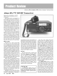
http://www.rv3apm.com/KB.html
Product Review & Short Takes Columns from QST Magazine
February, 2003
Product Reviews
High Power Antenna Tuners:
• AMERITRON ATR-30
• MFJ-986
• PALSTAR AT1500CV
• TEN-TEC 238A
• VECTRONICS HFT-1500
Short Takes
Zapchecker
Gregoire TR-2000 Communications Headset
Copyright © 2002 by the American Radio Relay League Inc. All rights reserved.
http://www.rv3apm.com/KB.html
PRODUCT REVIEW
QST Reviews Five
High-Power Antenna Tuners
Reviewed by Jim Parise, W1UK, ARRL Technical Advisor
One piece of gear that finds its way into most everyone’s shack at one time or
another is an HF antenna tuner. First of all, the name “antenna tuner” is something of a misnomer. It does not tune the antenna at all, but acts as an impedance
transformer that provides your transmitting equipment with the proper load, usually 50 Ω. Who needs an antenna tuner? Well, anyone who has the need to match
an antenna with an impedance outside the range of their transmitter or amplifier’s
output circuits. Modern transceivers typically have built-in tuners that are capable of matching SWR mismatches up to 3:1. Beyond that they need help, and
if you use an amplifier you most surely will need one. Many hams find themselves with limited antenna choices and the desire to operate on frequencies
other than what they were designed for, or use non-resonant multiband antennas that require a tuner.
The five HF tuners we tested are all in the kilowatt class, meaning the manufacturer rates their power handling capability at 1 kW output or more. With the
wide range of frequencies in the HF spectrum and the huge diversity of antenna types in use, tuners are expected to perform under an incredible number
of possible combinations. Some are more efficient at it than others. A measure of a tuner’s ability to transform impedances efficiently is energy loss.
Under extreme conditions a tuner can get quite hot or arc over at power
levels well under the manufacturers rating. Heat in a tuner is a product of
loss. RF energy being dissipated as heat is lost power that will not find its
way to your antenna and onto the air.
Tuner losses generally get higher as the impedance of the load decreases.
If a ham were running 1500 watts into a tuner that was 50% efficient, 750
watts would be dissipated in the tuner. Most of the loss in a tuner occurs in the
coil, and no coil can withstand 750 watts of power. A high-power tuner could
probably be safely used at 50% efficiency and 100 watts, but hams should be
careful with high SWR and high power, or a tuner failure is a real possibility.
Each tuner was tested into impedances that ranged from 6.25 to 400 Ω, and
their respective percentage of loss and 1.5-SWR bandwidth measured. The
tuners were also used in everyday communications on all bands at power levels up to 1 kW, matching a G5RV fed with balanced ladder line and a 160meter inverted L fed with coax.
Table 1
Comparison of Five Antenna Tuners
Ameritron
ATR-30
MFJ
MFJ-986
Palstar
AT1500CV
Ten-Tec
238A
Vectronics
HFT-1500
Circuit type
T-network
T-network
T-network
L-network
T-network
SWR/wattmeter
Cross-needle
Cross-needle
Cross-needle
Single-needle
Cross-needle
Balun type
4:1 current
4:1 current
4:1 voltage
4:1 voltage
4:1 voltage
Manufacturer’s claimed
PEP rating
3000 W
3000 W
1500 W
2000 W
2000 W
Manufacturer’s claimed
matching range
35-500 Ω
35-500 Ω
20-1500 Ω
5-3000 Ω
Not specified
Physical dimensions
(HWD) in inches
5.25×13×14.4
4.1×11×15.2
4.5×12.5×12
5.5×13×11
5.5×12.5×12
Brennan Price, N4QX
Assistant Technical Editor
[email protected]
From February 2003 QST © ARRL
http://www.rv3apm.com/KB.html
AMERITRON ATR-30
The ATR-30 is Ameritron’s legal limit
T-network antenna tuner offering. It is
housed in a plain, all black aluminum
enclosure with a scratch resistant coated
front panel. A look under the cover reveals two large variable capacitors and an
air core edge wound silver plated roller
inductor. Like most of the other tuners reviewed here, the capacitors are adjusted
with vernier reduction drives, and although they tune smoothly, they require
a lot of force to turn. The roller inductor
is adjusted with a plastic lever type knob
and is quite stiff to crank. The roller itself is a pinch roller, and the physical resistance in turning the crank may be offset by lessoned contact resistance.
The balun is constructed with three
large cores and wound with wire covered
with Teflon tubing. The cross-needle
meter displays both average and peak
power in switchable 300 W or 3 kW
ranges. The wattmeter requires dc to
function. It is illuminated by either a
12-V barrel connector on the back panel
or a 9-V battery accessible through a trap
door on the bottom of the unit. With
12 V, both the meter and inductor turns
counter are illuminated. When a 9-V battery is used, the meter will function, but
the panel lamps will not light.
Finding a match on 80 meters on the
G5RV required quite a bit of time finding the right combination of capacitor
tuning and inductance, and the stiff controls didn’t make it much fun. Finding
the sweet spot on the higher bands was
much easier.
There are three coax outputs on the
ATR-30, including two that may be
switched direct or through the T-network
and a third direct only. Single or balanced
feed lines connect to large ceramic binding posts with wing nuts.
Manufacturer: Ameritron, 116 Willow Rd, Starkville, MS 39759; tel
662-323-8211; fax 662-323-6551; www.
ameritron.com. Price: $599.95.
Front panel of the Ameritron ATR-30.
From February 2003 QST © ARRL
Table 2
Ameritron ATR-30
SWR
8:1
Load (Ω)
6.25
4.1
12.5
2:1
25
1:1
50
2:1
100
4:1
200
8:1
400
Power Loss %
1.5 SWR BW
Power Loss %
1.5 SWR BW
Power Loss %
1.5 SWR BW
Power Loss %
1.5 SWR BW
Power Loss %
1.5 SWR BW
Power Loss %
1.5 SWR BW
Power Loss %
1.5 SWR BW
160 m
20
1
15
3
10
4
<10
>5
<10
>5
<10
>5
<10
>5
80 m
12
3
<10
4
<10
>5
<10
>5
<10
>5
<10
>5
<10
>5
40 m
<10
>5
<10
>5
<10
>5
<10
>5
<10
>5
<10
>5
<10
>5
20 m
<10
4
<10
>5
<10
>5
<10
>5
<10
>5
<10
>5
<10
>5
10 m
<10
>5
<10
>5
<10
>5
<10
>5
<10
>5
<10
5
<10
3
Notes
Power losses are expressed as a percentage. A 21% loss of power is 1 dB.
The 1.5-SWR Bandwidth (SWR BW) represents the bandwidth over which an SWR of 1.5:1
or less was maintained as a percentage of the measurement frequencies (1.8, 3.5, 7.2,
14.2 and 29.7 MHz).
Interior circuitry of the Ameritron ATR-30.
Rear panel connections on the Ameritron ATR-30.
http://www.rv3apm.com/KB.html
MFJ-986
The 986 is one of more than 20 antenna tuner products currently offered by
the prolific MFJ. It is rated for 1500 W
PEP within the 35-500 Ω impedance
range, positioning it alongside the 989C
as one of their high power units. Unlike
the traditional T-network with a pair of
variable capacitors, the 986 makes use
of a single variable capacitor and a wire
wound air core roller inductor with a
three digit turns counter. The tuner uses
what MFJ describes as a “differential”
capacitor. It has two discrete sets of fixed
plates and one variable set, with a single
capacitor control, forming a T-network
with the inductor.
The cabinet is narrow and extends
nearly 18 inches deep. The cross-needle
meter has a high (3000 W) and low (300
W) setting switched by a front panel button, and it can display average and peak
power as well as SWR. Providing 12 V
to the connector on the back panel
brightly illuminates the meter. Both the
capacitor and roller inductor are directly
driven. The inductance knob has a finger depression, such as often found on a
transceiver’s tuning knob. It is somewhat
awkward to turn due to binding. The
tuner had a tendency to creep around the
operating desk when the inductor is rapidly turned. A check inside revealed several loose screws holding the inductor to
the chassis. Tightening these did improve
the smoothness somewhat.
The 986 provided a match to both antennas quickly, but arced over on 80
meters with the inverted L at 900 W.
While this tuner does provide ease of use,
one should give careful consideration to
the loss figures in the tables. During operation the meter developed an intermittent problem with both needles going off
scale even with very low power applied
and a low SWR. Movement of the SWR
bridge circuit board on the inside back
panel seemed to correct the problem.
Two coax outputs are provided that can
be switched to bypass the tuning circuit,
Front panel of the MFJ-986.
Table 3
MFJ-986
SWR
8:1
Load (Ω)
6.25
4.1
12.5
2:1
25
1:1
50
2:1
100
4:1
200
8:1
400
Power Loss %
1.5 SWR BW
Power Loss %
1.5 SWR BW
Power Loss %
1.5 SWR BW
Power Loss %
1.5 SWR BW
Power Loss %
1.5 SWR BW
Power Loss %
1.5 SWR BW
Power Loss %
1.5 SWR BW
160 m
47
1
33
1
25
1
22
2
15
3
11
3
10
3
80 m
31
1
22
1
20
2
12
3
10
5
<10
>5
<10
>5
40 m
21
2
14
4
10
4
<10
>5
<10
>5
<10
>5
<10
>5
20 m
16
4
12
5
<10
>5
<10
>5
<10
>5
<10
>5
11
>5
10 m
13
>5
11
>5
10
>5
<10
>5
19
>5
<10
>5
16
5
Notes
Power losses are expressed as a percentage. A 21% loss of power is 1 dB.
The 1.5-SWR Bandwidth (SWR BW) represents the bandwidth over which an SWR of 1.5:1
or less was maintained as a percentage of the measurement frequencies (1.8, 3.5, 7.2,
14.2 and 29.7 MHz).
Interior circuitry of the MFJ-986. When viewed from the side, two sets of fixed plates
are seen on the differential capacitor.
as well as a third output for a dummy load.
Balanced and single-wire feed lines connect to large ceramic feed through posts
with wing nuts. A 4:1 two-core current
balun is provided at the output.
Manufacturer: MFJ Enterprises, Inc,
PO Box 494, Mississippi State, MS
39762; tel 800-647-1800; fax 662-3236551; www.mfjenterprises.com. Price:
$329.95.
Rear panel connections on the MFJ-986.
From February 2003 QST © ARRL
http://www.rv3apm.com/KB.html
PALSTAR AT1500CV
The Palstar AT1500CV is a T-network
tuner solidly constructed in a compact aluminum enclosure. Inside, the metering and
SWR bridge circuitry are encased in their
own aluminum boxes. The moderately
sized variable capacitors are mounted side
by side and feature large calibrated dials
and silky smooth vernier tuning that allows for precise adjustment. Palstar indicates that newer units incorporate a roller
bearing assembly which makes inductor
adjustment smoother. The roller inductor
is quite large. It is an air core silver plated
edge wound coil with heavy-duty ceramic
forms. Control of the inductor is via a lever handle and mechanical turns counter.
It is not as smooth as some of the other
tuners and tends to lurch as it is rotated
during fine adjustments. The cross-needle
meter displays SWR and average forward
and reflected power in 300 and 3000 W
ranges, with no option for peak power
metering. It is illuminated with 12 V from
an included wall adapter.
Achieving a 1:1 SWR on the G5RV
was possible on all bands from 80 through
10 meters at its rated power maximum of
1000 W single tone. Similar results were
noted on the inverted L. Although the tuning chart provided in the manual does not
include settings for 30 meters, the tuner
easily matched both antennas on that band.
This tuner has a solid feel to it and doesn’t
creep around while making adjustments.
In laboratory tests, the AT1500CV had
more difficulties on 160 meters than on
other bands. A 1:1 SWR was only obtainable with the 25 and 50-Ω loads. Even at
those loads, the power losses at 160 meters
were measurably greater than those on
other bands at the same loads. The variable capacitors are 240 pF maximum,
which explains the 160 meter performance.
The tradeoff results in lighter weight.
Antenna connections on the back panel
include three coax inputs. Two are available direct or through the tuning network
and one is bypassed straight through. The
bypass output can also be used with an
optional 4:1 balun available for $39.95.
Balanced or single wire feed lines are attached to Delrin terminal posts with wing
Front panel of the Palstar AT1500CV.
From February 2003 QST © ARRL
Table 4
Palstar AT1500CV
SWR
8:1
Load (Ω)
6.25
4.1
12.5
2:1
25
1:1
50
2:1
100
4:1
200
8:1
400
Power Loss %
1.5 SWR BW
Power Loss %
1.5 SWR BW
Power Loss %
1.5 SWR BW
Power Loss %
1.5 SWR BW
Power Loss %
1.5 SWR BW
Power Loss %
1.5 SWR BW
Power Loss %
1.5 SWR BW
160 m
No Match
No Match
21
2
13
3
No Match
No Match
No Match
80 m
25
1
16
2
13
3
<10
>5
<10
>5
<10
>5
<10
>5
40 m
16
2
13
4
<10
>5
<10
>5
<10
>5
<10
>5
<10
>5
20 m
12
>5
<10
>5
<10
>5
<10
>5
<10
>5
<10
>5
<10
>5
10 m
12
3
11
>5
<10
>5
<10
>5
13
>5
12
>5
<10
5
Notes
“No Match” means that a 1:1 SWR could not be obtained.
Power losses are expressed as a percentage. A 21% loss of power is 1 dB.
The 1.5-SWR Bandwidth (SWR BW) represents the bandwidth over which an SWR of
1.5:1 or less was maintained as a percentage of the measurement frequencies (1.8, 3.5,
7.2, 14.2 and 29.7 MHz).
nuts. Longer threaded material on the terminal posts would be a welcome improvement and make attachment of larger gauge
wire much easier.
In one isolated circumstance during
lab testing, our engineer felt an RF bite
on 10 meters through the metal portion
of the inductor crank. This did not seem
to be a pervasive problem, and Palstar indicates that the grounding on the crank
has also recently been improved.
Manufacturer: Palstar, Inc, 9676 N
Looney Rd, PO Box 1136, Piqua, OH
45356; tel 937-773-6255; fax 937-7738003; www.palstarinc.com. Price:
$429.95, optional 4:1 balun $39.95.
Interior circuitry of the Palstar AT1500CV.
Rear panel connections on the Palstar AT1500CV.
TEN-TEC 238A
The Ten-Tec 238A is the only tuner
in our roundup to utilize an L-network.
Using an innovative switching arrangement, the 238A actually provides five different circuit configurations to maximize
efficiency. A look at the low loss figures
in the table confirms this. The well-constructed tuner makes us of a single variable capacitor and a smooth turning wire
wound roller inductor to match impedances up to 3000 Ω. Additional capacitance is switched into the circuit by
means of a front panel switch. Five settings each are available for high and low
impedances, as well as a bypass choice.
A ceramic feed through post on the back
panel provides a connection to add an
additional 1000 pF capacitor (included
with the tuner) to the circuit for matching 160 meter antennas. The small dual
use meter can be switched to display
SWR or RF power in either a 2000 or
200 W range. The meter lamp is powered by 12 V on the back panel.
The 238A handily matched all bands
on both test antennas at full legal limit
power. On 10 meters using the G5RV, the
capacitor and inductor controls were a bit
sensitive to small adjustments. One minor complaint: Measuring forward power
in the high power range on the meter
caused the indicator to slap the right extreme position during CW keying.
In laboratory tests, the 238A did not
match on 160 meters into a 6.25-Ω load
until 2700 pF of external capacitance was
added. Ten-Tec indicates they will provide
additional capacitors to purchasers at no
extra charge. Also, the power losses on 10
meters were considerably greater than those
on other bands. However, the 238A performed very admirably on most other
bands, quite often exhibiting the least losses
on given band and load combinations.
The four-position antenna switch on the
front panel allows selection of four coax
outputs or a balanced/random wire. The
balanced output and one coax connector
share position four. A two-core balun
is provided for matching the balanced
output.
Front panel of the Ten-Tec 238A.
Table 5
Ten-Tec 238A
SWR
8:1
Load (Ω)
6.25
4.1
12.5
2:1
25
1:1
50
2:1
100
4:1
200
8:1
400
Power Loss %
1.5 SWR BW
Power Loss %
1.5 SWR BW
Power Loss %
1.5 SWR BW
Power Loss %
1.5 SWR BW
Power Loss %
1.5 SWR BW
Power Loss %
1.5 SWR BW
Power Loss %
1.5 SWR BW
160 m
No Match
<10
>5
<10
>5
<10
>5
<10
>5
<10
>5
<10
>5
80 m
<10
>5
10
>5
10
>5
<10
>5
<10
>5
<10
>5
<10
>5
40 m
<10
>5
<10
>5
<10
>5
<10
>5
<10
>5
<10
>5
<10
>5
20 m
<10
>5
<10
>5
<10
>5
<10
>5
<10
>5
<10
>5
10
>5
10 m
28
2
22
2
17
3
<10
>5
20
4
20
4
13
1
Notes
“No Match” means that a 1:1 SWR could not be obtained, even with the included 1000 pF
external capacitor attached. A match on 160 m at 6.25 Ω was achieved with 2700 pF of
external capacitance; the power loss was less than 10%, and the 1.5 SWR BW was
greater than 5%.
Power losses are expressed as a percentage. A 21% loss of power is 1 dB.
The 1.5-SWR Bandwidth (SWR BW) represents the bandwidth over which an SWR of 1.5:1
or less was maintained as a percentage of the measurement frequencies (1.8, 3.5, 7.2,
14.2 and 29.7 MHz).
Since we purchased our review unit,
Ten-Tec has produced a substantially
identical antenna tuner, the 238B. The
Tennessee manufacturer is now selling
only the 238B model.
Manufacturer: Ten-Tec, 1185 Dolly
Parton Pky, Sevierville, TN 37862; tel
865-453-7172; fax 865-428-4483; www.
tentec.com. Price: $475.00 (current
model 238B).
Interior circuitry of the Ten-Tec 238A. The 238A is the only one of the
five tuners reviewed here without an air-core inductor. The inductor
here has a linen phenolic core.
Rear panel connections on the Ten-Tec 238A.
From February 2003 QST © ARRL
VECTRONICS HFT-1500
The first thing you notice about the
HFT-1500 is the LED bar graph on the front
panel, which is used to display relative
peak forward power. The bright green bar
graph is adjusted to its maximum scale with
a level control on the front panel to a known
forward power reading on the cross-needle
wattmeter. While it doesn’t show actual
power readings, it does give a quick visual
indication of peak power. The cross-needle
meter displays only average power and
SWR in two power ranges selected by a
pushbutton switch. The traditional Tnetwork design uses two 4.5-kV variable
capacitors adjusted with large comfortable
knobs and very smooth vernier tuning. This
tuner stays put on the desk while you utilize a lever handle and gear driven 5 digit
mechanical turns counter to adjust the air
wound roller inductor.
Tuning the 160-meter inverted L and the
G5RV on all bands except 10 meters was
easily accomplished, with no problems
handling 1 kW. In the field, the best SWR
that could be obtained on 10 was 2.33:1;
this is possibly due to the additional “loading” when a human touches the all-metal
inductor crank. The ARRL Lab adjusted
the inductor with a wooden pencil in some
cases to obtain a match.
The HFT-1500 provides two coax inputs
and a third that completely bypasses the
tuning network. The balanced and single
wire inputs are Delrin terminal posts connected to a large single core 4:1 voltage
balun.
In some circumstances during lab testing, our engineer felt RF bites through the
metal portion of the inductor crank. Later
units feature a metal shaft bushing, which
provides a better ground. This was not experienced in field testing, but tuner adjustments were not made at high power.
Manufacturer: Vectronics, 300 Industrial Park Rd, Starkville MS 39759;
tel 662-323-5800; fax 662-323-6551;
www.vectronics.com. Price: $459.95.
Front panel of the Vectronics HFT-1500.
From February 2003 QST © ARRL
Table 6
Vectronics HFT-1500
SWR
8:1
Load (Ω)
6.25
4.1
12.5
2:1
25
1:1
50
2:1
100
4:1
200
8:1
400
Power Loss %
1.5 SWR BW
Power Loss %
1.5 SWR BW
Power Loss %
1.5 SWR BW
Power Loss %
1.5 SWR BW
Power Loss %
1.5 SWR BW
Power Loss %
1.5 SWR BW
Power Loss %
1.5 SWR BW
160 m
45
1
32
>5
19
2
12
3
12
3
<10
4
<10
4
80 m
42
<1
31
>5
24
1
<10
>5
<10
>5
<10
>5
<10
>5
40 m
16
2
11
3
<10
>5
<10
>5
<10
>5
<10
>5
<10
>5
20 m
15
5
<10
>5
<10
>5
<10
>5
<10
>5
<10
>5
11
>5
10 m
8
>5
<10
>5
<10
>5
<10
>5
<10
>5
<10
>5
16
4
Notes
Power losses are expressed as a percentage. A 21% loss of power is 1 dB.
The 1.5-SWR Bandwidth (SWR BW) represents the bandwidth over which an SWR of
1.5:1 or less was maintained as a percentage of the measurement frequencies
(1.8, 3.5, 7.2, 14.2 and 29.7 MHz).
Interior circuitry of the Vectronics HFT-1500.
Rear panel connections on the Vectronics HFT-1500.
Antenna Tuner Testing Methods vs Accuracy
In the last round-up of manual antenna tuners, all of the
test data was created using the test methods devised by
Frank Witt, AI1H (described in depth in April and May 1995
QST). This method uses an antenna analyzer and measures
changes in SWR with changes in loads on the tuner. That
change in SWR can be used to calculate the tuner losses.
Following the Product Review, we received some correspondence that suggested that the method was insufficient to
produce “laboratory grade” accuracy in measurements. At the
time, this prompted some further investigation on the part of
ARRL Lab staff. The results of this study indicated that AI1H
method was reasonable over the useful range of the tuners
(the conditions for which the loss was reasonable). The Lab
concluded at the time that the accuracy decreased as the
tuner losses increased.
When the Product Review Editor brought the Lab another
collection of tuners to test, it was decided to employ a more
direct method of loss measurement, and to perform many
measurements by the AI1H method as well, so as to put the
issue to rest. By comparing the two sets of results, a reasonable conclusion could be drawn about the correlation of both
methods used.
In this review, the method used to measure the loss of the
tuners was as follows. Two test fixtures were built which would
hold combinations of high power 50-Ω “non-inductive” carbon
resistors (one fixture for parallel combinations and one for
series). Even with the non-inductive resistors, some net fixture
inductance was apparent at some frequencies, so a variable
capacitor was used to compensate. The fixture accuracy was
measured using the Lab’s vector impedance meter.
Each fixture used an input connection (for the tuner) and
an output connection. The output connection went to a 50-Ω
input power attenuator, which took the place of one of the
resistors in the load (for the series loads, it was always the
one on the ground side of the network). The output of the
power attenuator was connected to a high accuracy laboratory
wattmeter, and the actual attenuation was measured for
each frequency. The tuners were matched at low power, then
100 W of RF was applied at the input, with the output being
measured by the Lab’s wattmeter.
Because of the extra steps involved, the process was more
time consuming than the AI1H method. Therefore, to reduce
the required test time to a reasonable amount, the number of
This is how each tuner was connected for testing in the
ARRL Lab. A 100 W RF source (off picture rear) fed the
input of the tuner. The resistive load was connected to the
Ω power
antenna output. The load was connected to a 50-Ω
attenuator (off picture right), which took the place of the
final resistors.
tests were reduced by eliminating the 16:1 SWR tests (outside of the claimed matching range of most tuners) and by
eliminating the balanced output tests (non-trivial to perform
by the direct measurement method).
The results of these “direct method” tests appear in the
tables in this review. However, that still leaves the question of
how the older test method compares with these results. Before getting into the nitty-gritty, it should first be noted that a
variation of a few tenths of a decibel (excellent RF measurement precision indeed) translates to a significant difference in
loss percentage for relatively low losses. That is to say that if
one method indicates a loss of 3 percent and the other indicates a loss of 6 percent, a good portion of the difference is
in the limits of the measurement accuracy.
In comparing the results for both methods using the Lab’s
test equipment, when the tuner losses were less than 20
percent, there was excellent correlation between measurement methods (loss differences of 2-3 percent). For losses
between 20 and 40 percent, loss differences generally ranged
around 5-6 percent, with a couple of measurements that
differed by 7 percent. (An accuracy difference of 7% is about
0.3 dB.)
In a “big picture” examination, the raw data seemed to
suggest that one of the sources of error was related to the
measurement of reactive components in an impedance measurement. This is part of the 2:1 SWR measurements made in
the AI1H method. It appeared that for higher reactive values,
the measurements were not being accurately reported by the
antenna analyzer being used for the test. Given previous
tests of antenna analyzers, this is not entirely surprising. The
current spate of SWR analyzers in use by hams do a good
job at measuring the SWR and impedance of antenna systems. However, expected variations in the manufacture of
these types of equipment can lead to significant variations in
the results, especially with resonant loads as found in
matched antenna tuners. With the luck of the draw—as apparently happened with the ARRL Lab’s instrument—the
accuracy can be quite good, but the next meter off the shelf
might give different results under the same test conditions.
Although the differences in terms of percentage might be
relatively minor, reading 90% loss under circumstances
where the loss was really 80%, this “10%” difference does
mean a 3 dB change in the amount of power the tuner can
safely dissipate under those conditions, possibly a consideration for the high-power operator.
The bottom line is that the original test method was reasonably accurate, but not necessarily reproducible. To the
extent practical, the Lab will continue to use the moreaccurate “direct” method for future testing. The AI1H method
will still be used for some testing, but only with careful crosschecking of the instrumentation used.—Michael Tracy,
KC1SX, ARRL Lab
This is a close-up of the parallel load test fixture. The variable
capacitor was used to compensate for fixture inductance
encountered at some frequencies.
From February 2003 QST © ARRL
SHORT TAKES
Zapchecker
“Zapchecker” is an unusual name for a highly useful
device. In essence, the Zapchecker is a wideband (10 MHz to
4.5 GHz) receiver that provides visual indications of the presence of RF energy. Common field-strength meters do the same
thing, and they’ve been around for many years, but the
Zapchecker takes the concept several steps further.
The Zapchecker is a field-strength meter on steroids. First
of all, it is quite sensitive. When I turned on the Zapchecker, I
adjusted the sensitivity control to maximum, just to see what
would happen. What happened was a pinned meter needle and
a brightly glowing red LED. What was I picking up? The signal turned out to be emanating from the 900-MHz cordless
telephone my wife was using in an adjacent room.
After reducing the sensitivity considerably, I began walking around the house, waving the Zapchecker at any electronic
device I could find. When I passed it within about a foot of
my computer monitor, I saw a strong indication. No surprise
there. My monitor generates plenty of RF, to my everlasting
dismay. With the Zapchecker I was able to trace how RF was
being radiated not only from my monitor, but from various
interconnecting computer cables as well. The bright LEDs were
a big help during this test. When I reached behind and beneath
my station table, I couldn’t see the meter in the dim light, but
the red and green LEDs were easy to read.
The detecting antenna is the foam centered coil at top center.
The red piece of paper is taped over the potentiometer swing
point for protection. The motor at lower right generates the
vibrations when this feature is turned on. The vibrations are
pulsed by the LED at top right, which blinks (unseen)
periodically while in vibrate mode. The motor does not run
when the LED is lit. The ground wire to the batteries is
connected to the right of R17 (bottom left); it was separated for
this picture.
A Lot of Features in a Tiny Package
The Zapchecker is compact at only about 2 inches wide × 5
inches long × 1 inch thick, and it weighs just 5 ounces. It fits
easily in your hand and can slip into a shirt or pants pocket.
There are two switch-selectable measurement modes: Linear and Logarithmic. In the linear mode the Zapchecker has a
maximum sensitivity of 100 µV at 10 MHz. In the logarithmic
mode, the Zapchecker maintains a 45-dB logarithmic conformity. I found the linear mode to be best for detecting relatively weak signals, such as when I made some crude far-field
pattern measurements of my HF antenna.
The logarithmic mode is useful when you need to detect
sudden changes in strength. This may come in handy during
foxhunts when you are close to the “fox” transmitter. To test
the idea, I concealed a transmitter in a small area of our backyard and challenged my 8-year-old daughter to find it with the
Zapchecker. She managed to locate the fox in less than 10
minutes, and was so fascinated she wanted to do it again.
The Zapchecker offers a unique feature that may be of interest to the visually impaired. You can enable a vibrator mode
in which the Zapchecker will vibrate in varying degrees of
strength when it detects signals.
Serious Test Equipment
Using the Zapchecker for a back yard fox hunt. The red LED
glows when Zapchecker detects a strong signal.
Steve Ford, WB8IMY
From February 2003 QST © ARRL
My encounter with the vibrator mode notwithstanding, the
Zapchecker is a serious piece of test equipment. While testing
the unit for this review, I used the Zapchecker to hunt down
some RF leakage in our cable TV wiring. The sensitivity and
ease of use made short work of what might have been a frustrating search.
Manufacturer: Alan Broadband Company, 93 Arch St, Redwood City, CA 94062; tel 888-369-9627; www.zapchecker.
com/. $89 plus $7 shipping and handling.
QST Editor
[email protected]
SHORT TAKES
Gregoire TR-2000 Communications Headset
Reviewed by Steve Ford, WB8IMY
I put a Warren Gregoire & Associates TR-2000 headset to
the test during one of the most demanding phone contests of
the year—the 2002 Sweepstakes. I knew that I’d gain a fair
sense of what this low-cost headset could do within the first
few hours of SSB bedlam.
Before I could use the TR-2000, however, I had to adapt it
to my ICOM IC-706 transceiver. Gregoire & Associates offer custom connector installation, but I opted
for the hair-shirt approach
of doing it myself. The TR2000 sports an electret microphone, which means
that you must supply a polarizing voltage for it to operate. In the case of the TR2000 microphone, that was
9 V at about 100 µA. Like
many modern transceivers,
the IC-706 makes 9 V
available at the microphone
jack. The well-written instructions that accompany
the TR-2000 advise you to
Maty Weinberg, KA1EIB, models
place a 10 kΩ resistor in
the TR-2000 headset.
series with the voltage
source. The instructions
also suggest adding a 0.01 µF capacitor between the microphone and the transceiver mike jack to isolate the polarizing
voltage from the radio. Some radios don’t require the resistor
and capacitor, and my ’706 may be one of them, but I chose to
be safe rather than sorry.
The TR-2000’s 5-foot cord is divided into two sections:
the microphone wiring and the headphone cable. Both sections are shielded. The IC-706 and quite a few other radios
make the receive audio available at the microphone jack. I could
have wired the TR-2000’s headset directly to the microphone
jack in this fashion but for one drawback: The IC-706 doesn’t
mute the speaker audio unless you use the front-panel headphone jack. There’s no sense blasting the radio’s speaker to
From February 2003 QST © ARRL
the outside world while wearing headphones (it kind of defeats the purpose!), so I soldered a separate 1/8-inch plug to
the headphone section of the cord, plugged it into the headphone jack and thereby silenced the ’706. Now I could enjoy
deafening receive audio in my ears without annoying the rest
of the household.
Sweepstakes
The TR-2000 headset is light and comfortable. That’s important when you’re going to be spending hours on the air.
The foam ear cushions kept out much of the external noise
without squeezing my head like a vice. The headphone audio
seemed to emphasize the high and midrange frequencies.
The electret microphone element is on a spring-loaded
boom. As the instructions advise, you need to adjust the boom
by bending it radically in the direction that you wish it to go,
then allowing it to spring back. For obvious reasons, you must
remove the headset for this adjustment—at least to get the
boom position in the ballpark. Once you have the boom close
to its final destination, you can make fine adjustments while
wearing the headset. All this adjusting and springing takes a
little getting use to. On the other hand, when you finally reach
a position you’re happy with, the boom will stay put, even
when bumped.
For me, the best microphone position was resting right on
my lips. The TR-2000’s noise-canceling microphone element
is designed for very close talking. I found that the element
pickup dropped dramatically when it was more than about
1
/2-inch from my mouth.
Audio reports were consistently favorable. Even with my
low-profile station I had little trouble punching through pileups to compete for the rarer Sweepstakes sections.
Conclusion
The Gregoire TR-2000 worked flawlessly throughout the
contest. This comfortable headset is a winner, especially considering the cost. And if you want to shave about $15 off the
price, you can purchase the TR-2000 as a kit. Not a bad deal
at all.
Manufacturer: Warren Gregoire & Associates, 229 El
Pueblo Place, Clayton, CA 94517; tel 800-634-0094;
www.warrengregoire.com. $44.95, assembled and tested,
without connectors; $29 kit without connectors.