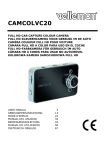
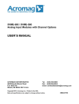
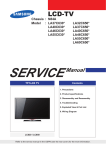
1
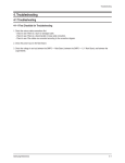
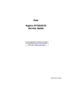
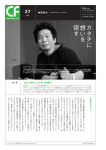
Troubleshooting
4. Troubleshooting
4-1 Troubleshooting
4-1-1 First Checklist for Troubleshooting
1. Check the various cable connections first.
- Check to see if there is a burnt or damaged cable.
- Check to see if there is a disconnected or loose cable connection.
- Check to see if the cables are connected according to the connection diagram.
2. Check the power input to the Main Board.
3. Check the following voltages;
- SMPS to the Main board
- SMPS to the X Main board
- SMPS to the Y Main board
- SMPS to the Logic board.
Samsung Electronics
4-1
Troubleshooting
4-1-2 Checkpoints by Error Mode
■ No Power
Symptom
- The LEDs on the front panel do not work when connecting the power cord.
- The SMPS relay does not work when connecting the power cord.
- The unit appears to be dead.
Major
Checklist
The SMPS relay or the LEDs on the front panel does not work when connecting the power cord if the cables
are improperly connected or the Main Board or SMPS is not functioning. In this case, check the following:
- Check the internal cable connection.
- Check the fuses.
- Check the output voltages of the SMPS.
- Replace the Main Board.
START
Is the AC
power cord
connected?
NO
Insert the
power cord
and retest.
NO
Insert the
connector
and retest.
Are fuses F801S,
FS801S, or FS803
blown?
NO
Replace the
fuse(s) and
retest.
YES
On CN801, pin 4,
is there 5V STBY? NO
Problem
Solved?
YES
NO
YES
YES
Problem
Solved?
NO
YES
Troubleshooting
Procedures
YES
NO
YES
Is the ac inlet,
(CN800S)
connected?
Problem
Solved?
Replace the
SMPS and
retest.
Problem
Solved?
YES
NO
Replace the Main
PCB and retest
End
4-2
Samsung Electronics
Troubleshooting
■ When the unit is repeatedly turning on and off
Symptom
Major Checklist
- The SMPS relay is repeatedly turning on and off.
In general, the SMPS relay repeatedly turns on and off by the protection function due to a defect on a board
connected to the SMPS.
- Disconnect all cables from the SMPS, operate the SMPS alone and check if the SMPS works properly and if
each voltage output is correct.
- If the symptom continues even when SMPS is operated alone, replace the SMPS.
- If the symptom is not observed when operating the SMPS alone, find any defective assemblies by
connecting the cables one by one.
START
Check the Va and Vs voltages
on the power supply.
Do the voltages
match the panel
sticker?
NO
Adjust the voltages
to match the panel
sticker and retest.
Problem
solved?
YES
NO
YES
Replace the Main
PCB and retest
Problem
solved?
YES
NO
Turn the unit off, wait for a short time.
Unplug the X and Y main boards from the
SMPS and then turn the unit on.
Troubleshooting
Procedures
Does the
SMPS stay
on?
Replace the
SMPS and
retest
NO
Problem
solved?
YES
NO
YES
Turn the unit off and wait a short time. Connect
only the Y main pcb then try turning the unit on.
Does the unit
stay on?
NO
Replace the Y Main
board and retest.
YES
Does the TV
have normal
operation?
YES
NO
Replace the X Main
board and retest.
Problem
solved?
NO
YES
Replace the logic
board
Problem
solved?
NO
Caution
END
YES
Replace the panel
When separating and connecting the cables such as CN800,CN801,CN802,CN803, CN804,CN805 of the
MAIN SMPS,CN4005 of the X MAIN Board, and CN5005 of the Y MAIN Board, a spark may be generated by
the electric charge of the high capacity capacitor. Therefore, wait some time after disconnecting the power cord
from the unit.
Samsung Electronics
4-3
Troubleshooting
■ No Sound
Symptom
Major Checklist
- Video is normal but there is no sound.
- When the speaker connectors are disconnected or damaged.
- When the sound processing part of the Main Board is not functioning.
- Speaker defect.
START
Is the speaker
connection made on
the Main PCB?
NO
(CN1501)
Make the
connection
and retest.
YES
NO
YES
Do pin 7 and 8 on
connector CN801
have 12V?
Troubleshooting
Procedures
Did the
problem
improve?
NO
Replace the
SMPS and
retest
Did the
problem
improve?
YES
NO
YES
Is the speaker output
terminal on the main
board normal?
NO
Replace the
Main PCB
Did the
problem
improve?
YES
NO
YES
Replace the
speaker
END
4-4
Samsung Electronics
Troubleshooting
4-1-3 Faults and Corrective Actions
Symptom
A blank vertical cell (block) appears
on the screen.
Related Image
Causes and Countermeasures
Address buffer defect
- Replace the corresponding upper/
lower buffers (E, F or G)
COF defect (burnt)
- Replace the module
A green screen appears when the
TV is turned on.
The Scale is not reseting
- Replace the Main board
The OSD box appears but there is
no text.
Incorrect program version
- Check the version of each
program
- Replace the Main board
A blank upper (or lower) block
appears on the screen.
Samsung Electronics
Upper/Lower Y Buffer defect
- Replace the corresponding upper/
lower buffers
4-5
Troubleshooting
Symptom
Related Image
Causes and Countermeasures
Either the main or sub picture does
not appear.
Replace the Main board
A vertical green line appears on the
screen.
The SMPS voltage is incorrect
- Adjust the SMPS voltage
according to the voltage printed
on the module label
Dim screen (blurred in red)
X-Main board defect
- Replace the X-Main board
A blank screen appears
- Replace the Y-Main board
4-6
Samsung Electronics
Troubleshooting
4-1-4 Troubleshooting Procedures by assembly
►50”
No
Assembly
Major Symptoms
1
SMPS-PDP TV
No power, Blank screen, the Relay repeats On and Off
2
ASSY PDP MODULE P-X MAIN
Blank screen
3
ASSY PDP MODULE P-Y MAIN
Blank screen
4
ASSY PDP MODULE P-LOGIC MAIN
Blank screen, Screen noise
5
ASSY PDP MODULE P Y MAIN SCAN BUFFER
Blank screen
6
ASSY PDP MODULE P-ADDRESS E BUFFER
Corresponding Buffer Board block screen is blank
7
ASSY PDP MODULE P-ADDRESS F BUFFER
Corresponding Buffer Board block screen is blank
8
ASSY PCB MISC-MAIN
No Power, Abnormal screen for each input source, PIP screen trouble, Sound trouble
9
ASSY BOARD P-FUNCTION&IR
The side function key does not work properly.
The remote control does not work properly, the LED does not work properly.
5
1
2
3
4
8
9
6
Samsung Electronics
7
4-7
Troubleshooting
►58”
No
Assembly
1
2
3
4
5
6
7
8
9
10
SMPS-PDP TV
ASSY PDP P-X MAIN
ASSY PDP P-Y MAIN
ASSY PDP P-LOGIG MAIN
ASSY PDP P Y SCAN UPPER BOARD
ASSY PDP P Y SCAN LOWER BOARD
ASSY PDP P ADDRESS E-BUFFER
ASSY PDP P ADDRESS F-BUFFER
ASSY PDP P ADDRESS G-BUFFER
ASSY PCB MISC-MAIN
11
ASSY BOARD P-FUNCTION IR
Major Symptoms
No power, Black screen, the relay repeats On and Off
Blank screen
Blank screen
Blank screen, Screen noise
Blank screen
Blank screen
Corresponding Buffer Board block screen is blank
Corresponding Buffer Board block screen is blank
Corresponding Buffer Board block screen is blank
No power, Abnormal screen for each input source, PIP screen trouble, Sound trouble
The side function key does not work properly
The remote control does not work properly, the LED does not work properly
5
12
3
6
4
0
!
7
4-8
8
9
Samsung Electronics
Troubleshooting
4-2 Adjustment
4-2-1 Service Instruction
■ Before performing service.
1. Check if your measuring and test equipment is working properly.
2. Secure sufficient work space for disassembling the product.
3. Prepare a soft pad for disassembling the product.
■ Service adjustment after board replacement.
<If adjustment equipment is available>
① PDP Option of Factory Mode → set the Factory Data Type item as the suitable value of relevant model.
② Adjust Calibration of Factory Mode for each mode.
③ Adjust White Balance of Factory Mode.
<If adjustment equipment is not available>
① Write down the value of HDMI White Balance of Factory Mode before replacing Board.
② PDP Option of Factory Mode → set the Factory Data Type item as the suitable value of relevant model.
③ Set the value of HDMI White Balance with the value written down before.
Samsung Electronics
4-9
Troubleshooting
4-2-2 How to Access Service Mode
1. General Remote
To Enter: POWER OFF
MUTE
1
8
2
POWER ON
(Interval between key strokes: less than 3 sec)
To Exit: Power the unit off and then back on.
2. Factory Remote
To Enter: POWER ON
INFO
Factory Key (Interval between key strokes: less than 3 sec)
To Exit: Press the factory key twice (Pressing only once forces the TV into aging mode)
3. Settings when entering Factory mode
- Sharp Screen (Dynamic), Color Tone (Cool1), Factory (Dynamic CE Off)
4. Adjustment Procedures
- ▲▼ Key: Select an item.
- ◀▶ Key: Adjust the value up or down.
- MENU Key : Save the changes to the EEPROM and return to the higher-level mode.
- Using the Numeric (0~9) keys, you can select a channel.
- Using the SOURCE key, you can switch AV modes.
5. Initial SERVICE MODE DISPLAY State
Option
ADC/WB
Control
Advanced
Expert
T-STL5PAUSFC-XXXX
DTP-LP-XXXX-XX
DTP-LP-App-XXXX-XX
Option : 6110 00
ADC : HDMI O COMP O PC O AV O
EDID : SUCCESS
HDCP : SUCCESS
Build Date : XX-XX-XXXX
Date Of Purchase : XX/XX/XX
※The version of the firmware displayed at the bottom of the screen may differ and the firmware is subject to change for the
improvement of product functions.
※If you have adjusted the settings in Service Mode, you have to reset the product.
4-10
Samsung Electronics
Troubleshooting
4-2-3 Factory Data
1. Option
ITEM
Data
Range
50FSmL4(50”
)/58FMfK1(58”)
50FSmL4,58FMfK1
TUNER
SEC_Custom
ALPS, SEC_TI_SEC_INF,SEC_Custom
Region
USA
USA,KOR
DDR
0
0~2
Light Effect
OFF
ON, OFF
Factory Reset
Type
Model
Media Link Type
Canada,America, Mexico,S.America,Infolink ON,Infolink OFF
PDP GROUP
2. ADC W/B
ADC
ITEM
Data
Range
AV Calibration
Success
Success, Failure,Initial
Comp Calibration
Success
Success, Failure,Initial
PC Calibration
Success
Success, Failure,Initial
HDMI Calibration
Success
Success, Failure,Initial
Samsung Electronics
4-11
Troubleshooting
ADC Target
ITEM
4-12
Data
Range
1st_AV_Low
64
0 ~ 1020
1st_AV_High
880
0 ~1020
1st_AV_Delta
1
0 ~7
1st_COMP_Y_Low
64
0 ~1020
1st_COMP_Cb_Low
512
0 ~1020
1st_COMP_Cr_Low
512
0 ~1020
1st_COMP_Y_High
940
0 ~1020
1st_COMP_Cb_High
512
0 ~1020
1st_COMP_Cr_High
512
0 ~1020
1st_COMP_Delta
1
0 ~7
1st_PC_R_Low
16
0 ~1020
1st_PC_G_Low
16
0 ~1020
1st_PC_B_Low
16
0 ~1020
1st_PC_R_High
1004
0 ~1020
1st_PC_G_High
1004
0 ~1020
1st_PC_B_High
1004
0 ~1020
1st_PC_Delta
1
0 ~7
2nd_AV_R_Low
4
0 ~124
2nd_AV_G_Low
4
0 ~124
2nd_AV_B_Low
4
0 ~124
2nd_AV_R_High
940
0 ~1020
2nd_AV_G_High
940
0 ~1020
2nd_AV_B_High
940
0 ~1020
2nd_AV_Delta
1
0 ~7
2nd_COMP_R_Low
4
0 ~124
2nd_COMP_G_Low
4
0 ~124
2nd_COMP_B_Low
4
0 ~124
2nd_COMP_R_High
940
0 ~1020
2nd_COMP_G_High
940
0 ~1020
2nd_COMP_B_High
940
0 ~1020
2nd_COMP_Delta
1
0 ~7
2nd_PC_R_Low
4
0 ~124
2nd_PC_G_Low
4
0 ~124
2nd_PC_B_Low
4
0 ~124
2nd_PC_R_High
940
0 ~1020
2nd_PC_G_High
940
0 ~1020
2nd_PC_B_High
940
0 ~1020
2nd_PC_Delta
1
0 ~7
2nd_HDMI_R_Low
4
0 ~124
2nd_HDMI_G_Low
4
0 ~124
2nd_HDMI_B_Low
4
0 ~124
2nd_HDMI_R_High
940
0 ~1020
2nd_HDMI_G_High
940
0 ~1020
2nd_HDMI_B_High
2nd_HDMI_Delta
940
1
0 ~1020
0~7
Samsung Electronics
Troubleshooting
ADC RESULT
ITEM
Data
Range
1st_Y_GH
0
0 ~ 511
1st_Y_GL
0
0 ~ 511
1st_Cb_BH
0
0 ~ 511
1st_Cb_BL
0
0 ~ 511
1st_Cr_RH
0
0 ~ 511
1st_Cr_RL
0
0 ~ 511
2nd_R_L
0
0 ~ 255
2nd_G_L
0
0 ~ 255
2nd_B_L
0
0 ~ 255
2nd_R_H
0
0 ~ 255
2nd_G_H
0
0 ~ 255
2nd_B_H
0
0 ~ 255
ITEM
Data
Range
Sub Brightness
128
0 ~255
R-Offset
512
0 ~1023
G-Offset
512
0 ~1023
B-Offset
512
0 ~1023
Sub Contrast
128
0 ~255
R-Gain
512
0 ~1023
G-Gain
512
0 ~1023
B-Gain
512
0 ~1023
Movie R-Offset
512
0 ~1023
Movie B-Offset
512
0 ~1023
Movie R-Gain
512
0 ~1023
Movie B-Gain
512
0 ~1023
WB
Samsung Electronics
4-13
Troubleshooting
3. Control
EDID
ITEM
4-14
Data
Range
EDID ON/OFF
ON, OFF
EDID WRITE ALL
Failure, Success
EDID WRITE PC
Failure, Success
EDID WRITE HDMI
Failure, Success
EDID WRITE HDMI1
Failure, Success
EDID WRITE HDMI2
Failure, Success
EDID WRITE HDMI3
Failure, Success
EDID WRITE HDMI4
Failure, Success
EDID 1.2 PORT
Failure, Success
Samsung Electronics
Troubleshooting
Sub Option
ITEM
Data
RF Mute Time
600ms
SUB U-COM
OFF
RS-232 Jack
UART
Watchdog
ON
WD COUNT
0
SSC ON/Off
ON
SSC MRR
2
SSC MFR
2
SSC QLC
4
Gamma
0.93
PANEL DISPLAY TIME
0
Dimm Type
0
LVDS FORMAT
PDP
Language
2
UI COLOR
BLUE
TOOLS Support
1
LNA Support
0
Wiselink WithOut DB
with DB
WiseLink Movie
ON
WiseLink DLNA
ON
WiseLink Write
ON
NETWORK Support
Cable/Wireless
High Devi
OFF
Carrier Mute
ON
Volume Curve
US_KR
PWM MAX
256
DVOUT CD
0
CVBS CD
0
EDID Jack Ident
OFF
Info Link Server Type
operating
ND ADJ Support
ON
24Px4 Support
ON
Power Indicator Support
OFF
BD Wise Support
ON
RF Remocon Support
OFF
OTA Duration Test
OFF
Alternate Del
OFF
OTN Server Type
OFF
OTN Test Server
ON
OTN Support
ON
Range
OTN Reset
OTN Duration
OFF
OTN Fail Test
OFF
IIC BUS STOP
OFF
Visual Test
Disable
Checksum
View Log
Font Data Viewer
Samsung Electronics
4-15
Troubleshooting
PDP Option
ITEM
Data
PATTERN SEL
0
LOGIC CONNECT
OFF
PIXEL SHIFT TEST
OFF
PANEL VERSION
W3
PANEL INCH
50FHD
PANEL TYPE
144
PANEL TEMPERATURE
46(-46)
Range
LOGIC SW VERSION
LOGIC SW CHECKSUM
SAPC TIMER
ON
APC SPEED
SLOW
LOGIC USB D/L
OFF
Hotel Option
ITEM
Data
HOTEL MODE
OFF
Range
POWER ON CHANNEL
POWER ON BAND
POWER ON VOLUME
MIN VOLUME
MAX VOLUME
PANEL BUTTON LOCK
POWER ON SOURCE
Shop Option
4-16
ITEM
Data
Shop Mode
OFF
USB DEMO ON(SEC)
OFF
USB DEMO OFF(SEC)
OFF
Exhibition Mode
OFF
PLG_MAX_SHOP
130
Range
Samsung Electronics
Troubleshooting
Sound
ITEM
Data
SAP High Threshold
0x1ah
SAP Low Threshold
0x9h
Speaker Delay Normal
0x59h
Auxout Delay Normal
0x59h
Spdif Delay Normal
0x0h
Speaker Delay Game
0x28h
Auxout Delay Game
0x28h
Spdif Delay Game
0x0h
STA Amp Vol.
0x28h
STA Post Scale
0x6eh
STA Speaker EQ
ON
STA Sub Woofer
1
Mono to Stereo Thld
0x60h
Stereo to Mono Thld
0x30h
Pilot Level High Thld
0x30h
Pilot Level Low Thld
0x10h
Range
A2 Pilot AM Carr High Thld
A2 Pilot AM Carr Low Thld
NICAM Error High Thld
NICAM Error Low Thld
FM1 CarrMute High Thld
0x20h
FM1 CarrMute Low Thld
0x10h
DRC H Thresh
0x35h
DRC L Thresh
0x30h
DRC SW Thresh
0x3dh
Chattering Cnt
5
FM Prescale
AM Prescale
NICAM Prescale
BTSC Mono Prescale
20
BTSC Stereo Prescale
20
BTSC Sap Prescale
20
A2K Prescale
M Prescale
Samsung Electronics
4-17
Troubleshooting
Config Option
4-18
ITEM
Data
Num of ATV
1
Num of DTV
1
Num of AV
2
Num of SVIDEO
0
Num of COMP
2
Num of HDMI
4
Num of PC
1
Num of SCART
0
Num of DVI
0
Num of OPTICAL Link
0
Num of MEDIA
1
Num of PANEL KEY
6
Num of USB Port
0
MFT Offset
62.5
Select LCD/PDP
PDP
HDMI/DVI SEL
2
Indicator Led
ON
Wall Mount
OFF
Chelsea HV Flip
OFF
Num of DISPLAY
2
HDMI AV MUTE TIME
40
DVI/HDMI SOUND
Auto
HDMI HOT PLUG
Disable
HOT PLUG OFF HOLD TIME
1200ms
HDMI FLT CNT SIG
300ms
HDMI FLT CNT LOS
300ms
UNSTABLE BAN CNT
2500ms
HDMI Err Cnt
5
HDMI ROBIN
ON
HDMI Callback
ON
HDMI CTS Thld
7
HDMI CTS Cnt1
1
TMDS_EQ2_Boost
1
TMDS_EQ2_Gain
0
TMDS_PLL_Loop
3
TMDS_CPREG_BLEED
1
HDMI EQ
AUTO
HDMI Switch
SIL9287
Range
Samsung Electronics
Troubleshooting
4. Advanced
* How to access Hidden menu
set the cursor to advanced menu and press 0 → 0 → 0 → 0
FBE3
ITEM
BM_slope1
BM_slope2
BM_slope3
BM_slope4
BM_start
BM_start_max
Lfunc-basis
Hfunc-basis
Mean-Offset1
Mean-Offset2
Mean-Slope
ACR-Offset
ACR-th1
ACR-th2
Skin-Enable
Data
19
36
56
75
68
110
70
80
30
235
112
10
10
110
ON
Skin-UV
135
Sub color
M-Skin-UV
128
…
M-Sub Color
…
WB Movie
Item
W/B MOVIE ON/OFF
MODE
Color Tone
MSub Brightness
MSub Contrast
W3_Rgain
W3_Bgain
W3_Roffset
W3_Boffset
W2_Rgain
W2_Bgain
W2_Roffset
W2_Boffset
W1_Rgain
Samsung Electronics
Data
OFF
…
…
…
…
…
…
…
…
…
…
…
…
…
Item
W1_Roffset
W1_Boffset
Cool_Rgain
Cool_Bgain
Cool_Roffset
Cool_Boffset
Movie Contrast
Movie Bright
Movie Color
Movie Sharpness
Movie Tint
Movie Backlight
Movie Gamma
M_Sub_Gamma
Data
…
…
…
…
…
…
…
…
…
…
…
…
…
…
4-19
Troubleshooting
EPA Standard
Item
Standard Contrast
Standard Brightness
Standard Sharpness
Standard Color
Standard Tint
Standard Backlight
Range
0~100
0~100
0~100
0~100
-50 ~ 50
0 ~ 10
ALL Source
95
45
50
50
0
7
CH_VDEC
Item
AGC_mode
Gain_VCR
Y_Gain_Man
Range
0~1
0~1
0~8191
ALL Source
1
0
880
Item
CTI_level
ST_Beg_NTSC
VS_Slice_Level
Range
0~63
0~127
0~7
ALL Source
15
10
3
Saturation
0~255
128
HS_Slice_Level
0~15
6
Hue
0~255
0
FB_Delay_adj
0~7
0
Y_Shape_sel
0~63
13
RGB_Delay_adj
0~7
0
Y_Shape_SCM
C_Shape_sel
C_Shape_SCM
If_iir
If_filt_sel
LTI_en
LTI_level
CTI_en
SCM_STI_EN
0~63
0~31
0~31
0~1
0~31
0~1
0~127
0~1
0~1
29
4
4
0
0
0
0
0
0
h_pk_gain
v_pk_gain
h_pk_band
2d_pk_gain
2d_pk_band
slice_mod_fine
scm_fdet_lvl
bl_range
0~15
0~15
0~3
0~15
0~7
0~127
0~255
0~7
4
2
0
0
2
0
150
3
YC_Delay
Item
V_Delay_adj
U_Delay_adj
Range
0~7
0~7
ALL Source
0
0
AR_ADC
4-20
Item
RED CUTOFF
GREEN CUTOFF
BLUE CUTOFF
RED GAIN
GREEN GAIN
BLUE GAIN
PHASE
SOG_BW
SSC_PC
Range
-128~+127
-128~+127
-128~+127
-128~+127
-128~+127
-128~+127
0~31
0~7
0~31
ALL Source
0
0
0
0
0
0
16
0
6
RGB_DLY
0~3
3
Samsung Electronics
Troubleshooting
CH_DP
Item
Range
1:ON, 0:OFF
1:ON, 0:OFF
ALL Source
OFF
OFF
DCR
1:ON, 0:OFF
OFF
SD2HD_DCR
SD2HD_DE
SD2HD_SCL
SD2HD_LTI
SD2HD_NARS
SD2HD_DUR
SD2HD_Metric
Coring_ON_OFF
SD_CSC
HD_CSC
M_SD_CSC
M_HD_CSC
PC_SD_CSC
MJC_DBG
MB_STEPS
LIMIT_MV_STEP
GLOBAL_FALLBACK
LOCAL_FALLBACK
1:ON, 0:OFF
1:ON, 0:OFF
1:ON, 0:OFF
1:ON, 0:OFF
0~3
0~1023
0~255
1:ON, 0:OFF
OFF
OFF
OFF
OFF
0
50
225
ON
7094
7438
7094
7438
7094
0
72
80
48
5
MNR
0~8
0~2047
0~2047
0~255
0~255
NR
Item
OFF_Y
OFF_C
Noise_bias
OFF_YMAX
Range
0~255
0~63
0~31
0~255
0~255
ALL Source
20
6
1
128
128
Item
MED_Y
MED_C
Noise_bias
MED_YMAX
Range
0~255
0~63
0~31
0~255
0~255
ALL Source
80
19
1
155
155
OFF_FADER
0~255
180
MED_FADER
0~255
170
LOW_Y
LOW_C
Noise_bias
LOW_YMAX
0~255
0~63
0~31
0~255
0~255
65
18
1
140
140
HIGH_Y
HIGH_C
Noise_bias
HIGH_YMAX
0~255
0~63
0~31
0~255
0~255
90
20
1
165
165
LOW_FADER
0~255
160
HIGH_FADER
0~255
180
Samsung Electronics
4-21
Troubleshooting
Sharpness
Item
Pre_GainH1
Pre_GainH2
Pre_GainH3
Post_GainH1
Post_GainH2
Post_GainH3
Post_GainV1
Post_GainV2
Post_GainV3
CTI_Gain
Pre_LTIH
SD_TH
HD_TH
NORMAL_LTIH
NORMAL_LTIV
SD_LTIH
SD_LTIV
PRE_CORING
POST_CORING_H
POST_CORING_V
Pre_TOT
Post_TOT
Sub Color
Range
0~FF
0~FF
0~FF
0~FF
0~FF
0~FF
0~FF
0~FF
0~FF
0~F
0~3F
0~FF
0~FF
0~3F
0~3F
0~3F
0~3F
0~FF
0~FF
0~FF
0~3F
0~3F
30~80
ALL Source
10
15
10
10
15
10
40
50
40
15
4
100
132
8
4
16
24
32
32
32
32
32
59
Sharpness_LNA
Item
Pre_GainH1
Pre_GainH2
Pre_GainH3
Post_GainH1
Post_GainH2
Post_GainH3
Post_GainV1
Post_GainV2
Post_GainV3
ALL Source
7
11
7
7
11
7
30
37
30
CE_DIMMING
Item
Contrast Dimming
Dimming in Standard
Dimming in Moive
4-22
Range
ON/OFF
ON/OFF
ON/OFF
ALL Source
OFF
On
On
Samsung Electronics
Troubleshooting
LNA Plus
Item
Synctip_Noise
dB01_th
dB12_th
dB23_th
dB34_th
dB45_th
Range
0~4095
0 ~1023
0 ~1023
0 ~1023
0 ~1023
0 ~1023
ALL Source
16
48
73
185
318
FRC
FRCQ Option
Samsung Electronics
Item
SSC_OnOff
SSC_Width
SSC_Freq
FMD_Demo
PATT_BeforeDDR
PATT_AfterDDR
CSB Vertical
CSB Horizontal
X_VStabStatVid
X_VStabStatF
X_VStabCorF
X_VStabSensF
X_HaloSizStatVid
X_HaloSizStatF
X_HaloSizCorF
X_HaloSizSensF
Film_Low_SD
Film_Medium_SD
Film_High_SD
Film_Low_HD
Film_Medium_HD
Film_High_HD
Video_Judder_Low
Video_Judder_Med
Video_Judder_High
Hangup Detection
Q LVDS Sequence
Q LVDS Format
Q LVDS bit width
Range
ON
96
240
0
0
0
ON
ON
7
0
8
48
7
0
12
32
12 -> 32
3
0
12 -> 32
3
0
10 -> 0
5 -> 0
0
On
0-1-2-3
JEIDA
10bit
ALL Source
NO Dejudder
No Dejudder
blur max
blur max
4-23
Troubleshooting
FRCQ Fallback
Item
SensD_Film_Low
SensD_Film_Medium
SensD_Film_High
Rel_Start_Film
Rel_Slope_Film
H_Len_Start_Film
H_Len_Slope_Film
V_Len_Start_Film
V_Len_Slope_Film
SensD_Video
Rel_Start_Video
Rel_Slope_Video
H_Len_Start_Video
H_Len_Slope_Video
V_Len_Start_Video
V_Len_Slope_Video
Data
31
31
31
20
3
127
1
40
1
0
20
1
127
1
40
1
PQ Others
Item
7.5 IRE NTSC
7.5 IRE OFFSET
HDMI 48Hz Enable
HDMI Black level
Range
ON/OFF
0~256
On/ OFF
ALL Source
ON
60
OFF
Normal
5. Expert
ITEM
Data
N/D ADJ
OFF
Range
Source
4-24
Samsung Electronics
Troubleshooting
4-2-4 Service Adjustment
■ White Balance - Calibration
If picture color is wrong, do calibration first.
Execute calibration in Factory Mode
1. Source
: VIDEO
2. Setting Mode : NTSC-M (Mode: #3)
3. Pattern
: Pattern #24 (Chess Pattern)
4. Use Equipment : K-7256 or Equipment of equality level
5. Work order
1 Enter by Factory Mode select "2. WB Adjust".
2 Select “CALIBRATION”.
3 Select “AV CALIBRATION” again in CALIBRATION MENU.
4 After Completing Calibration, come out “Av success”. OSD on the screen (bottom-side) for about 3 seconds.
Source AV : NTSC composite, Component : 1280*720/60Hz
PC : 1024*768/60Hz
< Chess Pattern >
Samsung Electronics
4-25
Troubleshooting
■ White Balance
Adjust spec.
1. Source
: HDMI
2. Setting Mode : 1280*720@60Hz
3. Pattern
: Pattern #92
4. Use Equipment : MIK-7256 (MSPG925L)
5. Work order
①Connect HDMI (DVI) output terminal of MIK-7256 (MSPG925L) to the HDMI input in main set
②Set the input to HDMI mode
③Enter the White Balance menu of service mode
④Contact CA-210 sensor to glass filter
< Fixed Position of CA210 Probe >
⑤ Adjust the low light
- Adjust Sub-Bright to set the ‘Y’ value
- Adjust R-Offset (‘x’) and B-Offset (‘y’) to the color coordinates.
* Do not adjust G-Offset data
⑥ Adjust the high light
- Adjust Sub-Contrast to set the ‘Y’ value
- Adjust R-Gain (‘x’) and B-Gain (‘y’) to the color coordinates.
* Do not adjust the G-gain data
4-26
Samsung Electronics
Troubleshooting
<50”
(CA-210)
Input mode
x
y
Y(L)
T(K), MPCD
CVBS
(NTSC)
H/L
278
285
Don’t Control
(Sub_CT:133)
10,500/±0
L/L
278
285
7.3 cd/m² (2.2 Ft)
10,500/±0
COMP
(720P)
H/L
278
285
Don’t Control
(Sub_CT:133)
10,500/±0
L/L
278
285
7.3 cd/m² (2.2 Ft)
10,500/±0
HDMI
(720P)
H/L
278
285
Don’t Control
(Sub_CT:133)
10,500/±0
L/L
278
285
7.3 cd/m² (2.2 Ft)
10,500/±0
<58”)
(CA-210)
Input mode
x
y
Y(L)
T(K), MPCD
CVBS
(NTSC)
H/L
278
285
Don’t Control
(Sub_CT:133)
10,500/±0
L/L
278
285
6.9 cd/m² (2 Ft)
10,500/±0
COMP
(720P)
H/L
278
285
Don’t Control
(Sub_CT:133)
10,500/±0
L/L
278
285
6.9 cd/m² (2 Ft)
10,500/±0
HDMI
(720P)
H/L
278
285
Don’t Control
(Sub_CT:133)
10,500/±0
L/L
278
285
6.9 cd/m² (2 Ft)
10,500/±0
Samsung Electronics
4-27
Troubleshooting
4-2-5 Replacements & Calibration
* Check items listed after changing each
No
Replaced assembly items
Check Items
1
ASSY PCB MISC-MAIN
①Auto Program
②White Balance Adjust
2
SMPS-PDP TV
Vs, Va voltage check and adjust
3
ASSY PDP MODULE P-X MAIN
4
ASSY PDP MODULE P-Y MAIN
5
ASSY PDP MODULE P Y MAIN SCAN BUFFER
6
ASSY PDP MODULE P-X MAIN SCAN LOWER
7
ASSY PDP MODULE P-ADDRESS E-BUFFER
8
ASSY PDP MODULE P-ADDRESS F-BUFFER
9
ASSY BOARD P-FUNCTION&IR
Not to be adjusted
※When replacing the SMPS or PDP panel, you have to check the voltage printed on the panel sticker and adjust it.
4-28
Samsung Electronics
Troubleshooting
■ Voltage Adjustment
1. After replacing the SMPS or PDP panel, you must adjust the voltage referring to the voltage label printed on the panel.
(If you do not adjust the voltage, an abnormal discharge symptom may appear.)
Value
UF1
Vs
207
Va
56
Ve
97
Vsc
-197
Board Adjustment
SMPS
SMPS
Voltage Label
2. A point of adjusting SMPS-MAIN voltage.
VS Test Point
VS Adjustment
VA Test Point
VA Adjustment
Samsung Electronics
4-29
Troubleshooting
■ SMPS Output Voltage
Y Drive
CN804
Vs, Va, Vg(15V)
X Drive
CN803
Vs, Vg(15V)
CN802
5.3V, PS_ON
VS_ON
CN801
PS_ON, VS_ON, STBY5.3V
15V, 18Vamp
CN800S
Nominal Regulation
MAIN B’D
LOGIC B’D
AC
Output Voltage
Output Current
Variable
Range
Min
Max
Peak
Typical
Load
Characteristics
Usage
1
Vs
198V
±1.5%
195~210
0.0 A
2.4 A
15.0 A
2.0 A
Pulsating
Drive
2
Va
55V
±2%
Fixed
0.0 A
2.0 A
13.0 A
1.5 A
Pulsating
Drive
3
D5.3V
5.2V
±5%
Fixed
0.0 A
6.5 A
7.0 A
4.5 A
Constant
Image, Logic
4
D15V
15V
±5%
Fixed
0.0 A
3.0 A
5.0 A
2.2 A
Constant/ Pulsating Image, Drive
5
15V_amp
18V
±5%
Fixed
0.0 A
3.0 A
5.0 A
0.5 A
Constant /Pulsating
Sound
6
STBY
5.2V
±3%
5V
0.0 A
1.0 A
1.5 A
0.3 A
Constant
Stand-by
4-30
Remark
step change
Samsung Electronics
Troubleshooting
■ Y-RR and Y-FR controls
Y-FR
Y-RR
Set the main reset (rising : 60usec, falling : 80usec) by change the value of variable resistor.
Y-RR
60usec
Y-FR
Y-RR
80usec
Y-FR
■ Wavefrom Adjustment (Y Main Output waveform)
(Y board 1st Sub-field wavefrom)
Samsung Electronics
4-31
Troubleshooting
TP Point
50”
58”
1. Waveform slope adjustment
(Y Board 1st. Subfield waveform)
2. Rising slope
1) Extend1st Sub-Field of Preset Rising Part.
2) Adjust the scale of scope to 50V, 10us division
3) Adjust waveform just like the following C(rising edge),D
4-32
Samsung Electronics
Troubleshooting
3. Falling slope
1) Extend1st Sub-Field of Main_Reset Falling Part.
2) Adjust the scale of scope to 50V, 10us division
3) Adjust waveform just like the following C(falling edge),D
Samsung Electronics
4-33
Troubleshooting
4-3 Upgrade
4-3-1 How to Check the Version of the Program
1. Procedures for checking in the Factory Menu.
When entering Factory Mode, the version of the software is displayed at the bottom of the menu as described on page 4-9.
Option
ADC/WB
Control
Advanced
Expert
T-CHEAUSC-0059
T-CHEAUSC-0021
SDAL-4.2.22-0099
RFS:12_64_512-13 T-CHEAUSC
2008-12-16
Type: NONE
Model: PNN0B650
EDID FAIL
CALIB: AV X COMP X PC X HDMI X
Option: 0b32 0010
Factory Data Ver: 200
DTP-AP-COMP-079-02
DTP-HIIG-0072-4
TLIB US3 1G 2008-12-15-01
DTP-BP-0083-01
Data of purchase: 2/6/2106
4-34
main program version
sub micom version
Samsung Electronics
Troubleshooting
4-3-2 How to Upgrading the Software
1. Insert a USB drive containing the firmware upgrade into the USB Upgrade Port on the
side of the TV.
TV side Panel
USB Drive
Energy Saving
: Off
PIP
Setup
2. Press the MENU button to display the menu.
Press the ▲ or ▼ button to select Support, then press the ENTER button.
SW Upgrade
►
3. Press the ▲ or ▼ button to select SW Upgrade, then press the ENTER button.
4. The message Scanning for USB... It may take up to 30 seconds. is displayed.
Software Upgrade
Scanning for USB.....
It may take up to 30 seconds.
5. If the firmware on the USB is properly recognized, the message Upgrade version xxxx to
Software Upgrade
version xxxx? The system would be reset after upgrade. is displayed.
Upgrade version XXXX to version XXXX ? The
system would be reset after upgrade.
Press the ◄ or ► button to select OK, then press the ENTER button. The upgrade
Cancel
OK
starts.
Please be careful not to disconnect the power or remove the USB drive while upgrades
are being applied. The TV will shut off and turn on automatically after completing the firmware upgrade.
►When software is upgraded, video and audio settings you have made will return to their default (factory) settings.
We recommend you write down your settings so that you can easily reset them after the upgrade.
4-3-3 BSP Version Update
1. BSP: uImage, pack.bin, rootfs.img, boot.img
2. Open [SpinelUS]update-XXXX.zip file in the USB file.
3. Equip USB in the state of set watchdog ‘OFF’, and progress upgrade with mute 7 8 9 exit.
Samsung Electronics
4-35