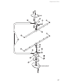
1
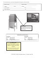
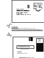
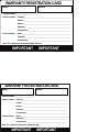
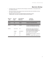
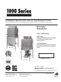
Installation Manual with Service Replacement Parts For Champion Models: DH-1000, DL-1000 • Moyer Diebel Models: MD1000HT, MD1000LT • Valu-Clean Models: VC1000, VC1000HT Door-type Dishwasher Model: 1000 Series High Temp Hot water sanitizing machine w/ pumped rinse and built-in stainless steel electric booster Low Temperature Chemical sanitizing machine w/ pumped rinse and 3 built-in chemical dispensing pumps High Temp C US Dishwasher serial no. Low Temp Issue Date: 4.23.08 Manual P/N 114313 rev. D For machines beginning with S/N D07106631 and above P.O. Box 4149 Winston-Salem, NC 27115 336/661-1556 Fax: 336/661-1660 Toll-free: 800.858.4477 2674 N. Service Road, Jordan Station Ontario, Canada L0R 1S0 905/562-4195 Fax: 905/562-4618 Toll-free: 800.263.5798 Printed in the USA For future reference, record your dishwasher information in the box below. Model Number__________________________ Serial Number_______________________ Voltage________________Hertz_____________ Phase__________________ Service Agent __________________________________ Tel:______________________ Parts Distributor _________________________________ Tel:______________________ For all models: The data plate mounts to the right-side of the top-mounted control cabinet. National Service Department In Canada: Toll-free: 800/ 263-5798 Tel: 905/ 562-4195 Fax: 905/ 562-4618 email: [email protected] In the USA: Toll-free: 800/ 858-4477 Tel: 336/ 661-1556 Fax: 336/ 661-1660 email: [email protected] ATTENTION: The dishwasher model no., serial no., voltage, Hz and phase are needed to identify your machine and to answer questions. Please have this information on-hand if you call for service assistance. COPYRIGHT © 2008 All rights reserved Printed in the USA ATTENTION: Complete the back of the POSTAGE PAID WARRANTY CARD below, then cut along the dashed lines and mail immediately to make sure that your machine warranty is validated. USE CANADIAN WARRANTY CARD IN CANADA AND USA WARRANTY CARD IN THE UNITED STATES. NO POSTAGE NECESSARY IF MAILED IN THE UNITED STATES BUSINESS REPLY MAIL FIRST-CLASS MAIL PERMIT NO. 2101 WINSTON-SALEM, NC POSTAGE WILL BE PAID BY ADDRESSEE MOYER DIEBEL PO BOX 4183 WINSTON-SALEM, NC 27119-0981 8"33"/5:3&(*453"5*0/$"3% .0%&- 4&3*"- %BUFPG*OTUBMMBUJPO@@@@@@@@@@@@@@@@@@@@@@@@ 0XOFST-PDBUJPO $PNQBOZ@@@@@@@@@@@@@@@@@@@@@@@@@@@@@@@@@@@@@@@@@@@@@@@@@@@@@@@@@ "EESFTT@@@@@@@@@@@@@@@@@@@@@@@@@@@@@@@@@@@@@@@@@@@@@@@@@@@@@@@ "EESFTT@@@@@@@@@@@@@@@@@@@@@@@@@@@@@@@@@@@@@@@@@@@@@@@@@@@@@@@ 5FMFQIPOF@@@@@@@@@@@@@@@@@@@@@@@@@@@@@@@@@@@@@@@@@@@@@@@@@@@@@ $POUBDU/BNF@@@@@@@@@@@@@@@@@@@@@@@@@@@@@@@@@@@@@@@@@@@@@@@@@@ 1VSDIBTFEGSPN %FBMFS@@@@@@@@@@@@@@@@@@@@@@@@@@@@@@@@@@@@@@@@@@@@@@@@@@@@@@@@@ 5FMFQIPOF@@@@@@@@@@@@@@@@@@@@@@@@@@@@@@@@@@@@@@@@@@@@@@@@@@@@@ $POUBDU/BNF@@@@@@@@@@@@@@@@@@@@@@@@@@@@@@@@@@@@@@@@@@@@@@@@@@ /PUFTIJTDBSENVTUCFSFUVSOFEUPWBMJEBUFXBSSBOUZ *.1035"/5*.1035"/5 8"33"/5:3&(*453"5*0/$"3% .0%&- 4&3*"- %BUFPG*OTUBMMBUJPO@@@@@@@@@@@@@@@@@@@@@@@@ 0XOFST-PDBUJPO $PNQBOZ@@@@@@@@@@@@@@@@@@@@@@@@@@@@@@@@@@@@@@@@@@@@@@@@@@@@@@@@@ "EESFTT@@@@@@@@@@@@@@@@@@@@@@@@@@@@@@@@@@@@@@@@@@@@@@@@@@@@@@@ "EESFTT@@@@@@@@@@@@@@@@@@@@@@@@@@@@@@@@@@@@@@@@@@@@@@@@@@@@@@@ 5FMFQIPOF@@@@@@@@@@@@@@@@@@@@@@@@@@@@@@@@@@@@@@@@@@@@@@@@@@@@@ $POUBDU/BNF@@@@@@@@@@@@@@@@@@@@@@@@@@@@@@@@@@@@@@@@@@@@@@@@@@ 1VSDIBTFEGSPN %FBMFS@@@@@@@@@@@@@@@@@@@@@@@@@@@@@@@@@@@@@@@@@@@@@@@@@@@@@@@@@ 5FMFQIPOF@@@@@@@@@@@@@@@@@@@@@@@@@@@@@@@@@@@@@@@@@@@@@@@@@@@@@ $POUBDU/BNF@@@@@@@@@@@@@@@@@@@@@@@@@@@@@@@@@@@@@@@@@@@@@@@@@@ /PUFTIJTDBSENVTUCFSFUVSOFEUPWBMJEBUFXBSSBOUZ *.1035"/5*.1035"/5 1000 Series - Revision History Revision History • The Revision History can contain part number changes, new instructions, or information that was not available at print time. • We reserve the right to make changes to these instructions without notice and without incurring any liability by making the changes.. • Equipment owners may request revised instructions, at no charge, by calling 1 (800) 858-4477 in the USA or by caling 1 (800) 263-5798) in Canada. Revision Date Revised Pages Serial Number Effectivity Revision Description 3.14.06 All D2466 Released first edition 2.15.07 All D5937 Revisions to consolidate manual 4.18.07 50-51 D5937 Add P/N 114236, thermometer to parts list 6.01.07 50, 54 D6336 SST timer assy replaces plastic cam timer Conversion kit P/N 900892 retrofits old timer P/N 0512018, & P/N 0512025 to P/N 417081 4.23.08 4, 6, 28, 30 All 5, 48,49 D07106631 11, 12 All 73, 74 All IFC All Changed water supply specification to 20 ± 5 psi/138 ± 35 kPa, recommend 0-60 psi/0-414 kPa pressure gauge install Control cabinet lock and key deleted Revised photos of timer switches Corrected header description for electrical schematics Added MDL Canadian PPD warranty card i Dear Owner: Thank you for choosing our dishwasher. We appreciate your business. This manual covers: High Temp High temperature door-type dishwasher with standard built-in booster in 40°F/22°C rise or an optional 70°F/39° C rise booster. Low Temp Low temperature chemical sanitizing door-type dishwasher with built-in chemical dispensing pumps for detergent, rinse-aid, and sanitizer. The installation, and initial start-up of your dishwasher must be performed by qualified electricians, plumbers, and authorized service technicians who are trained in commercial dishwashers. ii 1000 Series - Table of Contents Revision History... . ............................................................................................................ i Limited Warranty. .............................................................................................................. iv High Temperature Door-Type Dishwasher Installation Guide............................................................................................................. 1 Unpack and Place................................................................................................. 1 Electrical Connection............................................................................................. 5 Plumbing Connections.......................................................................................... 6 Chemical Dispensers........................................................................................... 9 Initial Start-Up........................................................................................................ 15 Operation......................................................................................................................... 19 Cleaning and Maintenance.............................................................................................. 21 Troubleshooting............................................................................................................... 23 Low Temperature Door-Type Dishwasher Installation Guide............................................................................................................. 25 Unpack and Place................................................................................................. 26 Electrical Connection............................................................................................. 29 Plumbing Connections.......................................................................................... 30 Chemical Dispensers........................................................................................... 32 Initial Start-Up........................................................................................................ 33 Operation......................................................................................................................... 36 Cleaning and Maintenance.............................................................................................. 37 Troubleshooting............................................................................................................... 40 All Models Service Replacement Parts............................................................................................. 43 Electrical Schematics...................................................................................................... 71 iii 1000 Series - Limited Warranty Limited Warranty Valu-Clean, Champion or Moyer Diebel (hereinafter referred to as the Company), P.O. Box 4982, Winston-Salem, North Carolina 27115 & 2674 N. Service Road, Jordan Station, Canada, L0R 1S0, warrants machines, & parts, as set out below. Warranty of Machines: Company warrants all new machines of its manufacture bearing the name the Company and installed within the United States and Canada to be free from defects in material and workmanship for a period of one (1) year after the date of installation or fifteen (15) months after the date of shipment by the Company , whichever occurs first. [See below for special provisions relating to glasswashers.] The warranty registration card must be returned to the Company within ten (10) days after installation. If warranty card is not returned to the Company within such period, the warranty will expire after one year from the date of shipment. The Company will not assume any responsibility for extra costs for installation in any area where there are jurisdictional problems with local trades or unions. If a defect in workmanship or material is found to exist within the warranty period, the Company, at its election, will either repair or replace the defective machine or accept return of the machine for full credit; provided, however, as to glasswashers, The Company ’s obligation with respect to labor associated with any repairs shall end (a) 120 days after shipment, or (b) 90 days after installation, whichever occurs first. In the event that the Company elects to repair, the labor and work to be performed in connection with the warranty shall be done during regular working hours by a Company authorized service technician. Defective parts become the property of Company. Use of replacement parts not authorized by the Company will relieve the Company of all further liability in connection with its warranty. In no event will the Company’s warranty obligation exceed the Company’s charge for the machine. The following are not covered by the Company’s warranty: a. Lighting of gas pilots or burners. b. Cleaning of gas lines. c. Replacement of fuses or resetting of overload breakers. d. Adjustment of thermostats. e. Adjustment of clutches. f. Opening or closing of utility supply valves or switching of electrical supply current. g. Cleaning of valves, strainers, screens, nozzles, or spray pipes. h. Performance of regular maintenance and cleaning as outlined in operator’s guide. i. Damages resulting from water conditions, accidents, alterations, improper use, abuse, tampering, improper installation, or failure to follow maintenance and operation procedures. j. Wear on pulper cutter blocks, pulse vanes, and auger brush. Examples of the defects not covered by warranty include, but are not limited to: (1) Damage to the exterior or interior finish as a result of the above. (2) Use with utility service other than that designated on the rating plate. (3) Improper connection to utility service. (4) Inadequate or excessive water pressure. (5) Corrosion from chemicals dispensed in excess of recommended concentrations. (6) Failure of electrical components due to connection of chemical dispensing equipment installed by others. (7) Leaks or damage resulting from such leaks caused by the installer, including those at machine table connections or by connection of chemical dispensing equipment installed by others. (8) Failure to comply with local building codes. (9) Damage caused by labor dispute. Warranty of Parts: The Company warrants all new machine parts produced or authorized by the Company to be free from defects in material and workmanship for a period of 90 days from date of invoice. If any defect in material and workmanship is found to exist within the warranty period Valu-Clean will replace the defective part without charge. DISCLAIMER OF WARRANTIES AND LIMITATIONS OF LIABILITY. VALU-CLEAN’S WARRANTY IS ONLY TO THE EXTENT REFLECTED ABOVE. VALU-CLEAN MAKES NO OTHER WARRANTIES, EXPRESS OR IMPLIED, INCLUDING, BUT NOT LIMITED, TO ANY WARRANTY OF MERCHANTABILITY, OR FITNESS OF PURPOSE. VALU-CLEAN SHALL NOT BE LIABLE FOR INCIDENTAL OR CONSEQUENTIAL DAMAGES. THE REMEDIES SET OUT ABOVE ARE THE EXCLUSIVE REMEDIES FOR ANY DEFECTS FOUND TO EXIST IN VALU-CLEAN DISHWASHING MACHINES AND VALU-CLEAN PARTS, AND ALL OTHER REMEDIES ARE EXCLUDED, INCLUDING ANY LIABILITY FOR INCIDENTALS OR CONSEQUENTIAL DAMAGES. The Company does not authorize any other person, including persons who deal in the Company’s dishwashing machines, to change this warranty or create any other obligation in connection with the Company’s Dishwashing Machines. iv 1000 Series HT - Installation Guide Installation Guide Unpack and Place (1000 Series HT) 1. Check the corrugated box that protected the dishwasher during shipment for punched holes or impact marks. 2. Inspect the shipping pallet for splintered or broken boards. 3. Inspect the exterior of the dishwasher while still mounted on the pallet for signs of damage. 4. Contact the freight company immediately if damage is found and save all packing for inspection to verify your damage claim. 5. Report the damage to your equipment supplier. They will contact our factory for repair or replacement of damaged components. 6. If no damage is found, proceed with lifting the dishwasher from its pallet. Be careful to lift the dishwasher by the main frame if using a forklift. 7. Make sure the four legs are screwed firmly in place after landing the machine. 8. Check the packing list to ensure all accessories are with the dishwasher. 9. Open the doors and remove the dishracks inside the machine. 10. Move the dishwasher close to its permanent location. 11. Locate the Installation Instructions attached to the front door of the dishwasher. These instructions should be used in conjunction with the detailed instructions contained in this manual. 12. Remove the protective covering from the dishwasher and identify the utility connections. Information cards and stickers must not be removed from the dishwasher until the installation is complete. 1 1000 Series HT - Installation Guide Installation Guide Unpack and Place (1000 Series HT) 1. The installation of your dishwasher must be performed by qualified service personnel. 2. Problems due to improper installation are not covered by the Warranty. 3. The dishwasher data plate is located on the right-side of the top-mounted control cabinet cover. 4. Study the configuration diagrams below. They show the 2 ways that the dishwasher may be positioned. Corner and straight-through dishwasher configurations Note: The correct corner installation places the dishwasher so the top-mounted controls are easy to reach. The minimum distance from wall to dishwasher is 4" [103mm]. The maximum distance is 6" [129]. The room ceiling height must be a minimum of 80" [2032mm] so the doors can be removed completely. 2 1000 Series HT - Installation Guide Installation Guide Unpack and Place (1000 Series HT) 1. All dishwashers ship in the straight-through configuation. 2. Relocate the tracks and remove the wall-side door link components to convert the dishwasher for corner operation. 2 1 Move Part 2 Move Part 1 3 Remove Interior Door Bracket 1 4 2 wa Remove Door Linkage ll 5 ll wa Adjust Door Spring Tension 3 1000 Series HT - Installation Guide Installation Guide Unpack and Place (1000 Series HT) 1. Compare the dishwasher and site utility connections. 2. Level the dishwasher by adjusting the bullet feet. 3. Raise the doors and check the door clearance to the ceiling. 4. Move the dishwasher to its permanent location. Note: Installers must follow applicable sanitation, safety, plumbing, and electrical codes and regulations; and work in accordance with best practices for dishwasher installation. Utility Connections - 1000 Series HT Power: 208-240V Single or Three Phase Water supply: 3/4" NPT hot water supply (140°F/60°C minimum) for 40° F/22°C rise booster 20 ± 5 psi/138 ± 35 kPa flow pressure. Installation of 0-60 psi/0-414 kPa pressure gauge (supplied by others) is recommended. 3/4" NPT hot water supply (110°F/43°C minimum) for 70°F/39°C rise booster 20 ± 5 psi/138 ± 35 kPa flow pressure. Installation of 0-60 psi/0-414 kPa pressure gauge (supplied by others) is recommended. Drain: 1-7/8" stainless steel, slip-fit hose connection Max flow: 15 Us gal/min. (13.5 Imperial gal/min) 57liters/min. Chemicals: 4 Detergent and rinse-aid products are supplied by a chemical supplier 1000 Series HT - Installation Guide Installation Guide Electrical Connection (1000 Series HT) Warning: The dishwasher must be electrically grounded according to all local codes and regulations governing the installation of electrical service. Warning: Disconnect the main electric supply and place a tag at the fuse or disconnect switch indicating that work is being performed on that circuit. 1. Locate the screw on each side of the top-mounted control cabinet. 2. Remove the screws, then lift the cover off the cabinet and set it aside. 3. Double-check that all power was disconnected from the dishwasher. 4. Locate the power cable knock out and main terminal block on the left-side of the cabinet. 5. Locate the Machine Electrical Connection Data Plate mounted near the terminal block. The MACHINE ELECTRICAL CONNECTION DATA PLATE is the certified authority for the dishwasher power requirements. DO NOT use electrical data from any other sourceunless an authorized factory representative instructs you to use other data. 6. Connect the electric service to the dishwasher. Cable knock-out Machine Electrical Connection Data Plate Main terminal block ATTENTION ELECTRICIAN The Model 1000HT dishwasher must not be turned ON at the dishwasher's power switch located on the front of the top-mounted control cabinet without performing an Initial Start-up at the same time. Powering the dishwasher without performing the Initial Start-up may damage the dishwasher's electrical circuits. 5 1000 Series HT - Installation Guide Installation Guide Water Connection (1000 Series HT) 1. Locate the built-in stainless steel booster on the left-side of the dishwasher. Note: The existing hot water supply lines to the dishwasher must be 3/4" NPT or larger. To the best of your ability inspect, and verify that all supply piping meets the 3/4" NPT requirement. Note: The installing plumber must connect a water supply line to the dishwasher that is equal to or greater than 3/4" NPT in size and a 3/4" pressure regulating valve, PRV, and a 0-60 psi/0-414 kPa pressure gauge (not supplied) Dishwasher water supply temperature and water pressure requirements: 140°F/60°C minimum for 40°F/22°C rise booster 3/4" NPT hot water supply (140°F/60°C minimum) 20 ± 5 psi/138 ± 35 kPa flow pressure. Installation of 0-60 psi/0-414 kPa pressure gauge (supplied by others) is recommended. 110°F/43°C minimum for 70°F/39°C rise booster 3/4" NPT hot water supply (110°F/43°C minimum) 20 ± 5 psi/138 ± 35 kPa flow pressure. Installation of 0-60 psi/0-414 kPa pressure gauge (supplied by others) is recommended. 2. Connect a 3/4” NPT hot water supply to the dishwasher at the line strainer. 6 Blank page This page intentionally left blank 7 1000 Series HT - Installation Guide Installation Guide Drain Connection (1000 Series HT) Continued from page 6 1. Locate the dishwasher drain connection underneath the machine frame. 2. Install a drain line conforming to local plumbing and health regulations. Drain: 1-7/8" stainless steel, slip-fit hose connection Max flow: 15 US gal/min. (13.5 Imperial gal/min) 57liters/min. Ventilation (1000 Series HT) 1. The factory has no requirements for vent hoods; but, local codes and regulations in your area supersede our suggestions. Consult your local building and health authorities for local requirements. 2. Dishroom ventilation must provide sufficient airflow to prevent excessive humidity in the work area. 200-400cfm/5.6- 11.3 k Liters/min - is sufficient. 3. The dishwasher must not be subjected to continual drafts or cold air. 8 1000 Series HT - Installation Guide Installation Guide Chemical Dispensers (1000 Series HT) 1. The 1000 Series HT high temperature dishwasher sanitizes with 180-195° F/82-91° C hot final rinse water. 2. Do not connect a sanitizer chemical dispenser to the 1000 Series HT. 3. You may wish to contact a chemical supplier to supply the chemical dispensers and chemicals for liquid detergent and liquid rinse-aid. (Consult your local listings). 4. The chemical supplier must adjust their dispensers to provide the proper dosages for the installed dispensing system. 5. The factory may have supplied the chemical dispensing system as an option. Your chemical supplier must adjust factory dispensers for the chemicals supplied also. Note: Manual dosing of detergent or rinse-aid is NOT RECOMMENDED for the 1000 Series HT dishwasher. Poor washing results may result if manual dosing is employed. Note: Cartridge detergent systems are NOT RECOMMENDED for the 1000 Series HT dishwasher. Poor washing results may result if installed on this model. 6. The factory recommends that the chemical injectors be installed in the right back corner of the hood as shown below. Factory installed injection points Recommended locations for chemical injectors for dispensing systems supplied by others. Continued on page 10 9 1000 Series HT - Installation Guide Installation Guide Chemical Dispensers (1000 Series HT) Continued from page 9 115VAC Power Connections for Chemical Dispensers FOR QUALIFIED INSTALLERS ONLY Warning: Chemical dispensers must be electrically grounded in compliance with applicable electric codes. Warning: Disconnect the main electric supply and place a tag at the fuse or disconnect switch indicating that work is being performed on that circuit. Caution: Connecting chemical dispensers at points other than those recommended by the factory may damage the dishwasher electrical system. . 1. Remove 2 screws securing the top-mounted control cabinet cover. Set the cover aside. 2. Locate the cycle timer mounted in the right-rear corner of the control cabinet. 3. Refer to the 1000 Series HT electrical schematic located at the end of this manual. 4. Find the following components shown on the electrical schematic at end of this manual. 10 1000 Series HT - Installation Guide L1 1 L2 2 L2 Installation Guide Chemical Dispensers (1000 Series HT) GND 3 208VAC/3PH/60/3 Main terminal block and ground lug Detergent dispensing pump & cycle Timer cam No.5 with timer microswitch 5.The main terminal board is the termination point for the incoming power and earth ground which is also called the chassis ground. 6.Chemical dispensers (not supplied by Factory) must be grounded to chassis to protect the dishwasher circuits if possible. Rinse-aid dispensing pump & cycle timer cam No.7 with timer microswitch Earth Ground also called Chassis Ground 5.The main terminal board is the termination point for the incoming power and earth groundwhich is also called the chassis ground. 6.Chemical dispensers (not supplied by Factory) must be grounded to chassis to protect the dishwasher circuits if possible. 7.The detergent signal and the rinse-aid signal terminals for your chemical dispensing pumps are provided on the common terminal of each Timer Cam microswitch (See diagrams above). Cam No.5 operates the detergent microswitch Cam No.7 operates the rinse-aid microswitch 8. Look to the right for the photo of a timer cam microswitch. Note the configuration of the switch, do you see how the common terminal is different than the Normally Closed (N.C.) and the Normally Open (N.O.) terminals? 9. Look again at the Cycle Timer and locate the Detergent Cam No.5 and the Rinse-aid cam No.7. Continued on page 12 11 1000 Series HT - Installation Guide Installation Guide Chemical Dispensers (1000 Series HT) Continued from page 11 10. There are 8 Cams on the cycle timer. They are numbered 1-8 starting at the timer motor side of the assembly. 11. Look at the underside of the detergent and the Rinse-aid timer microswitches and identify the common terminals. 12. Connect the hot lead for the detergent pump to the common terminal of Cam Switch No. 5. Make the connection using a 12-14 slip-on terminal. Do the same for the rinse-aid switch. 13. Now you must connect your pumps to the dishwasher neutral return. All white wires marked with No. 2 are neutral wires; however, you are not authorized to connect to any #2 wire that you may identify. 14. Run a 12 gauge white wire with spade terminal connector (not supplied) from your chemical dispensing pumps to the neutral #2 white wire located on the main power transformer in the control cabinet. 12 1000 Series HT - Installation Guide Installation Guide Chemical Dispensers (1000 Series HT) Caution: The NEUTRAL RETURN (#2 white wires) and Chassis Ground are not the same point electrically. Improper wiring to these points may result in unusual voltage readings and damage to the dishwasher's electrical circuits. STOP WORKING ON THE DISHWASHER AT ONCE, if you do not know the difference between a neutral return and chassis ground. ATTENTION INSTALLER DO NOT TURN ON the dishwasher power switch located on the front of the top-mounted control cabinet before the Initial Start-up is completed Powering the dishwasher as described above, without knowing for certain that the Initial Start-up was performed, may make you liable for any damages stemming from your actions. 13 1000 Series HT - Installation Guide Installation Guide Chemical Dispensers (1000 Series HT) Priming the chemical dispensers (Factory dispensers only) 1. Factory dispensers are optional equipment;however, an automatic dispenser mustbe installed by someone in lieu of the factory. 2. The dispensers are mounted on the right-hand side of the lower wash tank. 3. Chemical pick-up tubes are inserted into their respective containers. 4. Detergent and Rinse-aid chemical containers can be placed a maximum of 11" [280 mm] above the finished floor, (ABF). 5. Place the chemical containers as close to the dishwasher as possible. 6. Each day check the detergent and rinse-aid chemical containers to make sure they are at least 1/2 full. 7. Push and hold the 2-position prime switch located on the front of the top-mounted control cabinet. Push UP to prime the detergent and DOWN to prime the rinseaid. 8. Watch the chemical as it travels up the tube to the injection point sight-glass located on the right-hand side, top-rear corner of the machine. 9. Release the switch when the chemical enters the sightglass. 10. Chemicals should reach the sight-glass within 2 minutes of prime.A problem may exist if it takes longer than 3 minutes. Detergent/Rinse-aid Prime Switch (Optional) 14 Fill/Drain Switch Cycle Light DETERGENT FILL RINSE-AID DRAIN CYCLE Power Switch POWER ON OFF 1000 Series HT - Installation Guide Installation Guide Initial Start-up (1000 Series HT) CAUTION DO NOT flip the dishwasher power switch "ON" until you read the instructions below. 1. The built-in stainless steel electric booster was shipped without water. 2. A manila card located above the power switch explains how to turn the machine on for the first time. See step No. 10 on the next page for the first DISHWASHER POWER UP procedure. Let's begin the Initial Start-up: 1. Check the placement of the dishwasher: Compare the machine location with the building plan or consult the owner or the General Contractor for approval. Check that the dishwasher configuration straight-through or corner operation is correct (See page 2 for details). 2. Check that all options and/or accessories are installed. 3. Remove protective white wrapping, tape, and other packing materials and discard. 4. Remove any foreign materials from the interior of the machine. Continued on page 16 15 1000 Series HT - Installation Guide Installation Guide Initial Start-up (1000 Series HT) Continued from page 15 5. Check that the following utilities are connected to the dishwasher and ready for use: Electrical service Hot water supply Drain Ventilation (if required by local regulations). 6. Check the chemical connections and chemical containers to ensure that enough chemical supplies are available. 7. Turn on the water supply to the dishwasher. 8. Turn on the main power switch at the service disconnect switch. 9. Open the dishwasher doors fully. 10. Check upper and lower spray arms are in place and spin freely. 11. Check that the drain-overflow and pump screen are in place. 12. Check that the lower scrap screen is clean and in place. 16 1000 Series HT - Installation Guide Installation Guide Initial Start-up (1000 Series HT) POWER UP THE DISHWASHER: As stated on page 15, the dishwasher power switch must not be turned without reading the instructions below.: WASH 170 70 80 100 105 C F 0 NSF MODEL W 22 100 80 60 95 0 210 20 20 RINSEPRESSURE 180 90 50 40 P/N 108391 200 120 60 FILL 60 40 190 160 0 14 psi CYCLE POWER ON 80 20 CHAMPIONINDUSTRIES,INC. WINSTON-SALEM, NC 0 100 DRAIN USG OFF 13. Turn on the main power switch at the service disconnect switch. 14. Flip the dishwasher power switch UP to turn on the dishwasher. 15. Immediately, push the fill switch up and hold it in the up position until the water flows out of the wash tank and into the lower scrap screen. 16. Release the fill switch. 17. Open the dishwasher door fully and check the water level inside the tank. The proper water level is just below the overflow tube and 3" [76 mm] from the lower sprayarm support. Measure from the back of the support up the tank toward the rear wall of the dishwasher. 17a 17b 17c 17d 3" [76mm] Water line 17 1000 Series HT - Installation Guide Installation Guide Initial Start-up (1000 Series HT) 18. Operate the dishwasher for 10 cycles. Monitor the wash and final rinse gauges located on the lower front panel of the dishwasher to ensure the machine is maintaining the proper temperatures. In the USA, the NSF standards are: 150° F/66° C minimum wash temperature 180° F/82° C minimum final rinse temperature Note: In Canada, sanitary standards are regulated by each province. Consult your provincial authorities for temperature requirements and other sanitary standards. 19. Check the green cycle light. It should illuminate throughout the 90-second cycle, then go out at the end of the cycle. When the doors are raised, the cycle light should again illuminate for 3-seconds and then go out. The 3-second light indicates the timer is resetting. DO NOT CLOSE the doors until the cycle light goes out. 20. Check the dishwasher piping for leaks. 21. Check the drain connection and make sure the house drain piping handles the dishwasher drain flow. Max flow is 15 USgpm/58 lpm or 1.7 US gals/6.6 Liters per rack. 22. Check the operation of the doors. They should go up and down smoothly. Check the white door guides to ensure they move with the doors. 23. Inspect the table connections to the dishwasher making sure they are secure and sealed with 100% silicon sealant on the mating flanges. The soiled table must slope away from the dishwasher and the clean table must slope toward the dishwasher. 24. Remove the upper and lower sprayarms and check the condition of the sprayarm bearing O-rings. 25. The initial start-up is complete. Turn off power to the dishwasher. 18 Operation - 1000 Series HT Operation (1000 Series HT) 1. Make sure there is adequate supply of liquid detergent and rinse-aid. Check the chemical containers and refill if necessary. 2. Ensure internal circular tank screen, upper and lower spray arms and lower external scrap screen are clean and in place. 3. Close door. Turn POWER switch to the “ ON ” position. Lift “FILL/DRAIN” switch to the “FILL” position and hold for approximately 15-20 seconds, or until water flows from the wash tank into the lower scrap pan. 4. Check the wash temperature gauge. Minimum reading must be 150°F/66°C. Operate the dishwasher through 2 complete cycles to increase the wash temperature to 150°F/66°C. Check the temperature gauge reading on the front of the dishwasher to ensure minimum temperatures are maintained. 5. Open doors completely and slide pre-scrapped rack of dishes into dishwasher. Check that control panel green light is out. 6. Close doors to automatically start the cycle. Total cycle time is 90-seconds. 7. The RINSE SENTRY feature monitors the final rinse water temperature being generated in the built-in booster. The rinse sentry will extend the wash cycle in the event that the final rinse temperature is less than 180°F/82°C. Rinse Sentry deactivates when the final rinse water in the built-in booster is a minimum of 180°F/82°C. Then the dishwasher timed cycle will complete the wash cycle, drain and refill with the final rinse water and complete the cycle. (See page 20 for an in-depth explanation of the Rinse Sentry feature.) 8. The final rinse cycle begins after the dishwasher washes and then drains. The rinse-aid is automatically added to the wash tank. 9. Cycle ends when green cycle light goes out. Opening the doors anytime during the timed cycle will stop the dishwasher. The dishwasher will resume operation as soon as the doors are closed. The timed cycle will begin at the place where it had stopped. 10.Open door. Remove the clean rack of dishes and insert another rack of soiled dishes. 11.Repeat steps 5-10 until all wares are clean. Note: Wash temperature must be a minimum of 150°F/66°C for optimum wash performance. Final rinse temperature must be a minimum of 180°F/82°C and a maximum of 195°F/91°C for optimum sanitizing. 19 1000 Series HT - Operation Operation (1000 Series HT) The Rinse Sentry Feature The 1000 Series HT Rinse Sentry automatically monitors the final rinse water temperature in the built-in stainless steel electric booster heater. If the final rinse water in the booster falls below 180°F/82°C, the Rinse Sentry will extend the dishwasher's wash cyle time in order to give the booster heater additional time to provide the 180°F/82°C water temperature required. Sanitization using hot final rinse water: 1. The 1000 Series HT sanitizes dishware with hot final rinse water at a minimum temperature of 180°F/82°C. 2. The 1000 Series HT includes a built-in stainless steel electric booster heater which heats incoming water temperatures to 180-195°F/82-91°C. 3. With Rinse Sentry, if the final rinse temperature inside the booster tank is below the minimum 180°F/82°C, the timed cycle pauses the wash cycle until the minimum temperature is available. 4. If something is defective and the final rinse water cannot reach the 180°F/82°C, then the dishwasher will wash indefinitely. 5. This is usually the point where the operator realizes that the dishwasher has a problem because the wash cycles are way too long. Who is responsible for checking the final rinse water temperature? 1. Everyone in the dishroom; but, the operator has the main responsibility. 2. You are required to check to make sure that the final rinse water temperature gauge always reads a temperature of 180-195°F/82-91°C during the final rinse cycle. And, It is your job to immediately stop washing dishes if the temperature falls below the minimum temperature of 180°F/82°C. 3. Guess what? Most people will forget to check the final rinse temperature at least once in their careers! That's why the Rinse Sentry is a part of your dishwasher. Rinse Sentry constantly checks the final rinse water temperature to ensure the minimum required temperature of 180°F/82°C is available to sanitize the dishware for the health and safety of your guests. 20 Cleaning and Maintenance - 1000 Series HT Cleaning and Maintenance Cleaning and Maintenance (1000HT Series) 1. Leave the machine power switch in the ON position. Doors are fully closed. 2. Push and hold the “FILL/DRAIN” switch down in the “DRAIN” position for approximately 15-20 seconds. The water in the wash tank will drain completely. 3. Raise doors fully. Use caution, as metal surfaces may be hot. Allow interior to cool. 4. Rinse the interior of the dishwasher with fresh water. Wipe the interior with a soft cloth. Do not scrub the interior with scouring pads, nor harsh detergents. 5. Close the doors fully; the dishwasher will begin a normal cycle. At the end of the cycle, Push & hold the Fill/drain switch in the DRAIN position until the wash tank is empty 6. Flip the dishwasher power switch to the OFF position 7. Remove and clean circular wash tank screen. 8. Check the overflow /drain assembly. Ensure the drain seat is clean. 9. Loosen the upper and lower thumbscrews (Do not remove the screws) Remove upper and lower sprayarms. Flush the sprayarm nozzles and check the bearing o-rings. 10. Replace sprayarms (they are interchangeable) and tighten thumbscrews. 11. Replace circular tank screen. 12. Remove lower scrap screen. Empty debris and flush both sides with fresh water. 13. Check the drain pan and flush with clean water. 14. Wipe the exterior of the dishwasher with a soft cloth. Do not hose the exterior with water nor scrub with scouring pads or harsh detergents. 15. Replace lower scrap screen, circular screen, and leave doors open for overnight drying. 16. Check the chemical supplies to ensure there are adequate supplies for the next shift. 21 1000 Series HT - Cleaning and Maintenance Cleaning and Maintenance Cleaning and Maintenance (1000 Series HT) Thoroughly cleaning your dishwasher every day is very best maintenance that you can do!! Daily Maintenance 1.Keep your dishwasher and the surrounding area spotlessly clean. 2.Immediately report loose, broken or missing parts to your supervisor. 3. Check drains for flow restrictions. 4.Check the dishwasher for leaks. 5.Operate the dishwasher as explained in this manual. Monthly Maintenance 1.Inspect pump hoses, door linkage, springs, and exterior of dishwasher for wear. 2.Inspect the wash arm bearings and O-rings. 3.Check the condition of scrap screens,. and dishracks for bent or broken pieces. 4.Check the toggle switches and indicator lights for damage. 5.Check the wash pump motor for loud bearings and leaking pump seal. 6.Create a simple Maintenance Tracking System as a guide for service. Annual Maintenance 22 Call your authorized service agent or local service representative and schedule a complete inspection of your dishwasher by a trained professional. A Maintenance Tip - Schedule your annual maintenance when you can give the service agent unrestricted access to the dishwasher for at least 2 to 2-1/2 hours. 1000 Series HT - Troubleshooting Troubleshooting - (1000 Series HT) In order to find the cause of a breakdown or abnormal operating condition in your dishwasher please ensure that: 1. All switches are ON 2. Drain overflow tube is in place and seated 3. Wash pipe and rinse nozzles are clean 4. Spray arms are in their proper positions 5. Round screen is properly positioned 6. Detergent, sanitizer and rinse additive dispensers are adequately filled 8. Doors are fully closed. That wasn't it? Check for a solution below: Condition Cycle will not start Cause Solution Door not closed . . . . . . . . . . . . . . . . . Make sure doors are fully closed Door safety switch faulty . . . . . . . . . . Contact your service agency Main switch off . . . . . . . . . . . . . . . . . . Check disconnect Low or no water Main water supply is turned off . . . . . .Turn on house water supply Drain/overflow tube is not in place and seated . . . . . . . . . . . . . . Clean, replace and seat drain tube as needed. Faulty fill valve . . . . . . . . . . . . . . . . . . Contact your chemcial supplier. Continuous water filling Fill valve will not close . . . . . . . . . . . . Clean or replace Motor not running Defective contactor . . . . . . . . . . . . . . Contact your servicer Defective motor . . . . . . . . . . . . . . . . . Contact your servicer Wash tank water temperature Incoming water temperature is low when in use at machine too low Raise temperature to 140°F/60°C Defective thermometer . . . . . . . . . . . .Check or replace Defective solenoid valve . . . . . . . . . . .Check or replace Arms not rotating Rinse nozzles not clean . . . . . . . . . . . Clean Bearings worn . . . . . . . . . . . . . . . . . . .Replace Water supply pressure low . . . . . . . . . Check incoming water pressure Insufficient pumped spray Clogged intake screen . . . . . . . . . . . .Clean pressure Clogged spray pipe . . . . . . . . . . . . . . .Clean Low water level in tank . . . . . . . . . . . .Check drain and overflow tube, timer may need adjustment, contact servicer Defective pump seal . . . . . . . . . . . . . .Contact service agent Insufficient rinse or no rinse Faulty pressure regulating valve . . . . .Clean or replace Improper setting on pressure regulating valve . . . . . . . . . . . . . . . . . .Set static pressure to 35 psi Clogged rinse nozzle and/or pipe . . . . . . . . . . . . . . . . . . . . . . . . . . .Clean with paper clip/delime Improper water line size . . . . . . . . . . . Have installer change to proper size 3/4" NPT 23 1000 Series HT - Troubleshooting Troubleshooting (continued) (1000 Series HT) Condition Cause Solution Insufficient rinse or no rinse Faulty pressure regulating valve... Clean or replace Improper setting on pressure regulating valve............................. Set static pressure to 35 psi Clogged rinse nozzle and/or pipe................................................ Clean with paper clip/delime Improper water line size................ Have installer change to proper size 3/4" NPT Low final rinse temperature Low incoming water....................... Check valve to be sure it is clean and operating. Machine leaking Defective thermometer.................. Check for proper setting or replace Pump seal leaking......................... Replace seal Leaking at pump hose................... Contact your chemical supplier Leaking at doors............................ Check to make sure that doors are fully closed Water splashing out door Nozzles/End caps missing............. Replace caps Wash nozzles blocked................... Clean Arms not rotating........................... Replace bearings Door handle twisted....................... Adjust or replace handle Poor washing results Detergent dispenser not operating properly......................... Contact detergent supplier Insufficient detergents................... Contact detergent supplier Food Soil concentration too high in wash tank........................... Prescrap dishes throughly Leaking at chemical hose.............. Replace hoses Wash water temperature too low........................................... See condition “Wash Tank Water Temperature” above 24 Wash arm clogged......................... Clean Improperly scraped dishes............ Check scraping procedures Ware improperly placed in rack................................ Use proper racks. Do not overload racks Improperly cleaned equipment...................................... Unclog wash sprays and rinse nozzles to maintain proper pressure and flow conditions. Overflows must be open. Keep wash water as clean as possible. 1000 Series - Installation Guide Model 1000 Series LT Installation Guide 25 1000 Series LT - Installation Guide Installation Guide Unpack and Place (1000 Series LT) 1. The installation of your dishwasher must be performed by qualified service personnel. 2. Problems due to improper installation are not covered by the Warranty. 3. The dishwasher data plate is located on the right-side of the top-mounted control cabinet cover. 4. Study the configuration diagrams below. They show the 2 ways that the dishwasher may be positioned. Corner and straight-through dishwasher configurations. Note: The correct corner installation places the dishwasher so the top-mounted controls are easy to reach. The minimum distance from wall to dishwasher is 4" [103mm]. The maximum distance is 6" [129]. The room ceiling height must be a minimum of 80" [2032mm] so the doors can be removed completely. 26 1000 Series LT - Installation Guide Installation Guide Unpack and Place (1000 Series LT) 1. All dishwashers ship in the straight-through configuation. 2. Relocate the tracks and remove the wall-side door link components to convert the dishwasher for corner operation. 2 1 Move Part 2 Move Part 1 3 Remove Interior Door Bracket 4 1 2 wa Remove Door Linkage ll 5 ll wa Adjust Door Spring Tension 27 1000 Series LT - Installation Guide Installation Guide Unpack and Place (1000 Series LT) 1. Compare the dishwasher and site utility connections. 2. Level the dishwasher by adjusting the bullet feet. 3. Raise the doors and check the door clearance to the ceiling. 4. Move the dishwasher to its permanent location. Note: Installers must follow applicable sanitation, safety, plumbing, and electrical codes and regulations; and work in accordance with best practices for dishwasher installation. Utility Connections - 1000 Series LT Power: Water supply: 115VAC 15Amp circuit 3/4" NPT hot water supply (140°F/60°C minimum) 20 ± 5 psi/138 ± 35kPa flow pressure. Installation of 0-60 psi/0-414 kPa pressure gauge is recommended. Drain: 1-7/8" stainless steel, slip-fit hose connection Max flow: 15 Us gal/min. (13.5 Imperial gal/min) 57liters/min. Chemicals: Detergent, rinse-aid, and sanitzer pumps are standard equipment. Chemicals supplied by a chemical supplier Chemical Dispensing Pumps - Factory Installed -1000 Series LT 28 • All pumps use liquid chemicals • Detergent pump capacity = Factory setting for detergent = 165ml / min @ 108 RPM 10 sec. / 28ml • Sanitizer pump capacity = Factory setting for Sanitizer= 35cc/min @ 14RPM 14cc in 23 sec. maintains 50PPM concentration of 5.25% sodium hypochlorite during the final rinse cycle. • 21 ml / min @ 14RPM 10 sec. / 3.5 ml Rinse-aid pump capacity = Factory setting for rinse-aid 1000 Series LT - Installation Guide Installation Guide Electrical Connections (1000 Series LT) Warning: The dishwasher must be electrically grounded according to all local codes and regulations governing the installation of electrical service. Warning: Disconnect the main electric supply and place a tag at the fuse or disconnect switch indicating that work is being performed on that circuit. 1. Locate the control cabinet keys on the rear of the control cabinet. 2. Remove 1 key to unlock the cabinet; do not remove the other key. 3. Unlock the control cabinet and remove the cover. 4. Locate the power cord on the left rear side of the control cabinet. 5. Locate the Machine Electrical Connection Data Plate mounted near the terminal block. The MACHINE ELECTRICAL CONNECTION DATA PLATE is the certified authority for the dishwasher power requirements. DO NOT use electrical data from any other source unless an authorized factory representative instructs you to use other data. 6. Check the power cord terminal connections at the main terminal board. Machine Electrical Connection Data Plate Main terminal block 29 1000 Series LT - Installation Guide Installation Guide Water Connection (1000 Series LT) Water supply: 3/4" NPT hot water supply (140°F/60°C minimum) 20 ± 5 psi/138 ± 35kPa flow pressure. Installation of 0-60 psi/0-414 kPa pressure gauge is recommended. Note: Plumbing installer must connect a 3/4" NPT hot water supply line to the dishwasher. A 3/4" pressure regulating valve (PRV) (not supplied) must be installed in the water supply line and adjusted to 20 ± 5 psi/138 ± 35 kPa flow pressure. Installation of a 0-60 psi/0-414 kPa pressure gauge is recommended. Note: Under NO circumstances, may the installing plumber connect a water supply line to the dishwasher that is less than 3/4" NPT in size. (3/4" NPT line strainer not supplied) 30 1000 Series LT - Installation Guide Installation Guide Drain Connection (1000 Series LT) 1. Locate the dishwasher drain connection underneath the machine frame. 2. Install a drain line conforming to local plumbing and health regulations. Drain: 1-7/8" stainless steel, slip-fit hose connection Max flow: 15 Us gal/min. (13.5 Imperial gal/min) 57liters/min. Ventilation 1000 Series LT 1. The factory has no requirements for vent hoods; but, local codes and regulations in your area supersede our suggestions. Consult your local building and health authorities for local requirements. 2. Dishroom ventilation must provide sufficient airflow to prevent excessive humidity in the work area. 200-400cfm/5.6- 11.3 k Liters/min - is sufficient. 3. The dishwasher must not be subjected to continual drafts or cold air. 31 1000 Series LT - Installation Guide Installation Guide Chemical Dispensers (1000 Series LT) Note: Manual dosing of detergent or rinse-aid is NOT RECOMMENDED for the 1000 Series LT dishwasher. Poor washing results may result if manual dosing is employed.. Note: Cartridge detergent systems are NOT RECOMMENDED for the 1000 Series LT dishwasher. Poor washing results may result if installed on this model. Note: The 1000 Series LT chemical dispensers are standard equipment. There are 3 built-in dispensers located on the front of the 1000 Series LT top-mounted control cabinet. Consult a local commercial dishwasher chemical supplier for the set-up and operation of the dispensing system. 32 1000 Series LT - Installation Guide 1. Installation Guide Initial Start-Up (1000 Series LT) Check that the following utilities are connected to the dishwasher and ready for use: Electrical service Hot water supply Drain Ventilation (if required by local regulations). 2. Check the chemical connections and chemical containers to ensure that enough chemical supplies are available. 3. Turn on the water supply to the dishwasher. 4. Turn on the main power switch at the service disconnect switch. 5. Open the dishwasher doors fully. 6. Check upper and lower spray arms are in place and spin freely. 7. Check that the drain-overflow and pump screen are in place. 8. Check that the lower scrap screen is clean and in place. 33 Blank Page This Page Intentionally Left Blank 34 1000 Series LT - Installation Guide Installation Guide Initial Start-Up (1000 Series LT) POWER UP THE DISHWASHER: 1. Flip the dishwasher power switch UP to turn on. 2. Turn on the main power switch at the service disconnect switch. 3. Release the fill switch. 4. Open the dishwasher door fully and check the water level inside the tank. The proper water level is just below the overflow tube and 3" [76 mm] from the lower manifold measuring up the tank toward the rear of the dishwasher. 5. Operate the dishwasher for 10 cycles checking the temperature gauges to ensure the machine is maintaining the proper temperatures. 3" [76mm] Water line 140° F/60° C minimum wash temperature 140° F/60° C minimum final rinse temperature 6. To drain the dishwasher, leave the machine power switch in the ON position. Doors are fully closed. 7. Push and hold the “FILL/DRAIN” switch down in the “DRAIN” position for approximately 15-20 seconds. 8. The water in the wash tank will drain completely. 9. Open the doors and check that all water has drained for the machine. 10. The initial start-up is complete. 35 1000 Series LT - Operation Operation How to Operate your Dishwasher (1000 Series LT) 1. Make sure there is adequate supply of liquid detergent and rinse-aid, and sanitizer. Check the chemical containers and refill if necessary. 2. Ensure the overflow tube/drain ball are clean and in place, and the circular pump screen, upper and lower spray arms and lower external scrap screen are clean and in place. 3. Close door. Turn POWER switch to the “ON ” position. Lift “FILL/DRAIN” switch to the “FILL” position and hold for approximately 15-20 seconds, or until water flows from the wash tank into the lower scrap pan. 4. Check the wash temperature gauge. Minimum reading must be 120°F/49°C. Recommended optimum temperature should be140°F/60°C. Operate the dishwasher through 2 complete cycles to increase the wash temperature to 140°F/60°C optimum. Check the temperature gauge reading on the front of the dishwasher 5. Open doors completely and slide pre-scrapped rack of dishes into dishwasher. Check that control panel green light is out. 6. Close doors to automatically start the cycle. Total cycle time is 90-seconds. 7. The final rinse cycle begins after the dishwasher washes and then drains. The rinse-aid and sanitizer are automatically added to the wash tank. 8. Use a sodium hypochlorite (Chlorine) based sanitizer at a minimum concentration of 50PPM in the final rinse. Routinely check the 50PPM chlorine level with test strips (supplied by chemical supplier). 9. Cycle ends when green cycle light goes out. Note: Wash temperature must be a minimum of 140oF/60oC for optimum wash performance. Final rinse temperature must be a minimum 140oF/60oC for optimum sanitizing. 10. Open door. Remove the clean rack of dishes and insert another rack of soiled dishes. 11. Repeat steps 5-12 until all wares are clean. 36 1000 Series LT - Cleaning and Maintenance Cleaning and Maintenance How to Clean your Dishwasher (1000 Series LT) 1. Leave the machine power switch in the ON position. Doors are fully closed. 2. Push and hold the “FILL/DRAIN” switch down in the “DRAIN” position for approximately 15-20 seconds. The water in the wash tank will drain completely. 3. Raise doors fully. Use caution, as metal surfaces may be hot. Allow interior to cool. 4. Rinse the interior of the dishwasher with fresh water. Wipe the interior with a soft cloth. Do not scrub the interior with scouring pads, nor harsh detergents. 5. Close the doors fully; the dishwasher will begin a normal cycle. At the end of the cycle, Push & hold the Fill/drain switch in the DRAIN position until the wash tank is empty 6. Flip the dishwasher power switch to the OFF position 7. Remove and clean circular wash tank screen. 8. Check the overflow /drain assembly. Ensure the drain seat is clean. 9. Loosen the upper and lower thumbscrews (Do not remove the screws) Remove upper and lower sprayarms. Flush the sprayarm nozzles and check the bearing o-rings. 10. Replace sprayarms (they are interchangeable) and tighten thumbscrews. 11. Replace circular tank screen. 12. Remove lower scrap screen. Empty debris and flush both sides with fresh water. 13. Check the drain pan and flush with clean water. 14. Wipe the exterior of the dishwasher with a soft cloth. Do not hose the exterior with water nor scrub with scouring pads or harsh detergents. 15. Replace lower scrap screen, circular screen, and leave doors open for overnight drying. 16. Check the chemical supplies to ensure there are adequate supplies for the next shift. 37 1000 Series LT -Cleaining and Maintenance Cleaning and Maintenance How to Clean your Dishwasher (1000 Series LT) Warning: Electrocution or chemical burns may occur if untrained persons attempt the deliming procedure. Only qualified service personnel should delime the dishwasher. 1. The 1000 Series LT is equipped with a delime switch on the left front side inside the top-mounted control cabinet. 2. After all necessary preparations have been performed in accordance with the chemical supplier's instructions, the chemical supplier or qualified service agent may operate the delime switch to lock the dishwasher in a continuous wash mode. Refer to the photographs below: 3. 38 Flip the delime switch down to the wash position when the deliming is complete. 1000 Series LT - Cleaning and Maintenance Cleaning and Maintenance How to Maintain your Dishwasher (1000 Series LT) Thoroughly cleaning your dishwasher every day is very best maintenance that you can do!! Daily Maintenance 1. Keep your dishwasher and the surrounding area spotlessly clean. 2. Immediately report loose, broken or missing parts to your supervisor. 3. Check drains for flow restrictions. 4. Check the dishwasher for leaks. 5. Operate the dishwasher as explained in this manual. Monthly Maintenance 1. Inspect pump hoses, door linkage, springs, and exterior of dishwasher for wear. 2. Inspect the wash arm bearings and O-rings. 3. Check the condition of scrap screens,. and dishracks for bent or broken pieces. 4. Check the toggle switches and indicator lights for damage. 5. Check the wash pump motor for loud bearings and leaking pump seal. 6. Create a simple Maintenance Tracking System as a guide for service Annual Maintenance Call your authorized service agent or local service representative and schedule a complete inspection of your dishwasher by a trained professional. A Maintenance Tip - Schedule your annual maintenance when you can give the service agent unrestricted access to the dishwasher for at least 2 to 2-1/2 hours. 39 1000 Series LT -Troubleshooting Troubleshooting In order to find the cause of a breakdown or abnormal operating condition in your dishwasher please ensure that: 1. All switches are ON 2. Drain overflow tube is in place and seated 3. Wash pipe and rinse nozzles are clean 4. Spray arms are in their proper positions 5. Round screen is properly positioned 6. Detergent, sanitizer and rinse additive dispensers are adequately filled 8. Doors are fully closed. That wasn't it? Check for a solution below: Condition Cause Solution Cycle will not start Door not closed............................. Make sure doors are fully closed Door safety switch faulty................ Contact your service agency Main switch off............................... Check disconnect Low or no water Continuous water filling Motor not running Main water supply is turned off...... Turn on house water supply Drain/overflow tube is not in place and seated....................... Clean, replace and seat drain tube ...................................................... as needed. Faulty fill valve............................... Contact your chemcial supplier. Fill valve will not close................... Clean or replace Defective contactor........................ Contact your servicer Defective motor............................. Contact your servicer Wash tank water temperature..........Incoming water temperature is low when in use ...................................................... at machine too low ...................................................... Raise temperature to 140°F/60°C Defective thermometer.................. Check or replace Defective solenoid valve................ Check or replace Arms not rotating Rinse nozzles not clean................ Clean Bearings worn................................ Replace Water supply pressure low............ Check incoming water pressure Insufficient pumped spray pressure Clogged intake screen.................. Clean Clogged spray pipe....................... Clean Low water level in tank.................. Check drain and overflow tube, timer may ...................................................... need adjustment, contact servicer Defective pump seal...................... Contact service agent Insufficient rinse or no rinse Faulty pressure regulating valve... Clean or replace Improper setting on pressure regulating valve............................. Set static pressure to 35 psi Clogged rinse nozzle and/or pipe................................................ Clean with paper clip/delime Improper water line size................ Have installer change to proper size 3/4" NPT 40 1000 Series LT -Troubleshooting Troubleshooting (continued) Condition Cause Solution Low final rinse temperature Machine leaking Low incoming water....................... Check valve to be sure it is clean and ...................................................... operating. Defective thermometer.................. Check for proper setting or replace Water splashing out door Nozzles/End caps missing............. Replace caps Wash nozzles blocked................... Clean Arms not rotating........................... Replace bearings Door handle twisted . .................... Adjust or replace handle Leaking at chemical hose.............. Replace hoses Pump seal leaking......................... Replace seal Leaking at pump hose................... Contact your chemical supplier Leaking at doors............................ Check to make sure that doors are fully ...................................................... closed Poor washing results Detergent dispenser not operating properly......................... Contact detergent supplier Insufficient detergents................... Contact detergent supplier Food Soil concentration too high in wash tank........................... Prescrap dishes throughly Wash water temperature too low........................................... See condition “Wash Tank Water Temperature” above Wash arm clogged......................... Clean Improperly scraped dishes............ Check scraping procedures Ware improperly placed in rack................................ Use proper racks. Do not overload racks Improperly cleaned equipment...................................... Unclog wash sprays and rinse nozzles to maintain proper pressure and flow conditions. Overflows must be open. Keep wash water as clean as possible. 41 Blank Page This Page Intentionally Left Blank 42 1000 Series HT and 1000 Series LT - Service Replacement Parts Service Replacement Parts Models: 1000 Series HT • 1000 Series LT Illustrations Page Wash pump/motor assembly________________________________________________ 45 1000 Series HT • Built-in booster assembly_ ___________________________________ 47 1000 Series HT • Control cabinet enclosure____________________________________ 49 1000 Series HT • Conrtol cabinet assembly_ ___________________________________ 51 1000 Series LT • Control cabinet enclosure with chemical dispensing pumps__________ 53 1000 Series LT • Control cabinet assembly_____________________________________ 55 Top mounted assemblies __________________________________________________ 57 Lower wash tank and drain assembly_________________________________________ 59 Hood assembly__________________________________________________________ 61 Front panel, temperature gauges, scrap screen covers_ __________________________ 63 Dishrack track assembly___________________________________________________ 65 Sprayarm assembly_______________________________________________________ 67 (water inlet airgap, chemical injection sight-glass, door safety switch) 43 Replacement Parts Item No. Part No. Description Unit 1 ----------- motor pump 1 ea 2 0512015 complete motor/pump assy , 115VAC/60/1 1 ea 3 0512015-2 complete motor/pump assy , 220/60/1 1 ea 4 0512015-3 complete motor/pump assy , 220/60/3 1 ea 5 0512015-4 complete motor/pump assy , 220/50/3 1 ea 6 114134 water slinger 1 ea 7 114135 nut 10 ea 8 114136 screw 10 ea 9 114137 pump support 1 ea 10 114138 gasket 1 ea 11 114139 pump seal 1 ea 12 114140 washer 1 ea 13 114141 impeller, 60 Hz voltage 1 ea 13b 114324 impeller, 50 Hz voltage 1 ea 14 114142 washer 1 ea 15 114143 lock washer 1 ea 16 114144 impeller nut 1 ea 17 114145 pump housing 1 ea 18 114146 o-ring 1 ea 19 114147 cap nut 1 ea 20 0310943 pump motor support 1 ea 21 107340 hose clamp 4 ea 22 0510942 discharge hose 1 ea 23 0510941 suction hose 1 ea CAPACITORS 44 Qty. 114322 Capacitor. 50uf / 240VAC 114323 Capacitor. 15uf / 115VAC Replacement Parts 1/4-20 locknut 1/4" washer 1/4-20 locknut 1/4" washer 1/4-20 x 3/4" 1/4 x 20 washer 20 21 22 21 21 23 21 45 Replacement Parts Item No. Description Qty. Unit 1 109985 booster element o-ring 1 ea 2 111233 booster heater, 220V/60/1 & 3 9kW, 40°F rise 1 ea 3 112059 booster heater, 220V/60/1 & 3 12kW, 70°F rise 1 ea 4 107908 booster element cover 1 ea 5 110768 3/4" brass line strainer 1 ea 6 100184 3/4" brass close nipple 4 ea 7 111437 3/4" solenoid valve 115VAC 1 ea Nshown 108516 3/4" water solenoid valve coil 1 ea Nshown 109903 3/4" water solenoid rebuild kit 1 ea 8 102444 3/4" brass street elbow 1 ea 9 113178 3/4" barb fitting 1 ea 10 113269 hose clamp 1 ea 11 114121 3/4" ID red hose 7 ft. 12 100571 3/4" brass union 1 ea 13 101525 Tee reducing 3/4" x 1/2" x 3/4" 1 ea 14 110562 fixed high limit thermostat 1 ea 15 114236 finalrinse 16 110929 high limit box 1 ea 17 100930 high limit box panel 1 ea 18 0509042 booster cannister 1 ea 19 101210 1/8" brass plug 1 ea 20 109069 temperature control thermostat 1 ea 21 0512027 bushing 1 ea Nshown 107922 control thermostat metal box and base plate 1 ea 46 Part No. 1 ea Replacement Parts 1 2 3 4 5 11 6-32 x 1/4" screw 6-32 washer 10 6 17 7 10-32 nylon insert nut and washer 8 16 9 13 12 6 14 15 21 20 18 19 47 Replacement Parts Item No. Part No. Description Qty. Unit 1 331082 control cabinet cover 1 ea 2 107351 power switch 1 ea 3 0508551 green cycle light 1 ea 4 0510399 fill and drain switch 1 ea 5 0510399 detergent /rinse-aid prime switch (optional) 1 ea 6 331078 control cabinet wrap 1 ea 7 0510833-1 std. cntrl. panel decal w/o prime switch/ prior to S/N D5937 1 ea 8 0510833-11 opt. cntrl. panel decal w/ prime switch/ prior to S/N D5937 1 ea N/S 0510824-1 control cabinet lock w/2 keys prior to S/N D07106631 1 ea DECALS 48 7 Champion HT 114245 8 Champion HT Prime 114242 7 Moyer HT 114241 8 Moyer HT Prime 114244 7 Valu-Clean HT 114240 8 Valu-Clean HT Prime 114243 Replacement Parts 1 3 2 4 5 6 7 8 Hood 49 Replacement Parts Item No. 50 Part No. Description Qty. Unit 1 0501403 brass screw 1 ea ---- 0501533 brass nut 1 ea ---- 0501472 brass 1/8” flat washer 1 ea ---- 0501493 brass lock washer 1 ea 2 0504951 terminal block 1 ea 3 105514 booster heat contactor 1 ea 4 106402 fuse block 1 ea 5 0503749 terminal board 1 ea 6 900892 90-sec. timer conversion kit (Prior to S/N D6336) 1 ea 6 417081 90-sec. timer assy SST (For S/N D6336 and above) 1 ea 7 107351 power switch 1 ea 8 0508551 green cycle light 1 ea 9 0510399 fill/drain switch 1 ea ---- 0510399 optional detergent/rinse-aid prime switch 1 ea 10 111036 relay socket 1 ea 11 111068 120VAC relay 1 ea 12 109064 step down transformer 1 ea 13 108122 12 Amp motor contactor 1 ea 14 110806 motor overload 1 ea 14a 110806 motor overload 1 ea 15 113937 door safety switch magnet after S/N 5697 1 ea 15a 111026 door safety switch magnet before S/N 5697 1 ea 16 113719 door safety reed switch 1 ea 16a 111090 door safety reed switch before S/N 5697 1 ea 17 112484 ADTR-1.5 Amp fuse 2 ea 18 114236 thermometer, 8 ft. capillary 2 ea after S/N 5697 Replacement Parts 1 15 6 5 16 17 3 4 2 14 13 10 11 12 18 18 9 9 8 7 51 Replacement Parts Item No. 52 Part No. Description Qty. Unit 1 331081 control cabinet cover 1 ea 2 0510872-1 sanitizer & rinse aid pump mtr. 115VAC, 14RPM 2 ea 3 0510870-1 detergent pump motor, 115VAC, 108 RPM 1 ea 4 114203 pump head assy. 3 ea 5 108412 tube clamp SMP-2 14 ea 6 107928 clear sanitizer feed tubing 20 feet 7 107930 blue rinse-aid feed tubing 16 feet 8 107929 red detergent feed tubing 16 feet 9 0312062 control cabinet leg 4 ea 10 331077 control cabinet bottom 1 ea 11 107351 power switch 1 ea 12 0508551 green cycle light 1 ea 13 0510399 momentary switch 3 ea 14 0501373-1 delime switch 1 ea 15 114192 cycle counter 1 ea 16 decal VC:114237 / MD: 114238 / Champion: 114239 1 ea 17 0503695 detergent label 1 ea 18 0505483 rinse-aid label 1 ea 19 0503694 sanitizer label 1 ea 20 0306363 stiffener tube 3 ea 21 0501869 strainer 3 ea 22 114202 squeeze tube 3 ea 23 0510824-1 lock w/ 2 keys 1 ea Replacement Parts 23 1 13 14 2 3 11 12 Inner panel cut-out 19 18 17 16 10 15 4 22 1/4-20 x 1/4" truss-head screw 20 5 21 6 9 7 8 Sanitizer = white Rinse Aid = blue Detergent = red Hood 53 Replacement Parts Item No. 54 Part No. Description Qty. Unit 1 0501403 brass screw 1 ea ---- 0501533 brass nut 1 ea ---- 0501472 brass 1/8” flat washer 1 ea ---- 0501493 brass lock washer 1 ea 2 0510635 terminal block 1 ea 3 107369 pump motor contactor 25 FLA 1 ea 4 111036 relay socket 1 ea 5 111068 120VAC relay 1 ea 6 900892 90-sec. timer conversion kit (Prior to S/N D6336) 1 ea 6 417081 90-sec. timer assy SST (For S/N D6336 and above) 1 ea 7 0501373-1 delime switch 1 ea 8 114192 cycle counter 1 ea 9 0503749 terminal board 1 ea 10 0501399 momentary toggle switch 3 ea 11 0508551 green cycle light 1 ea 12 107351 power switch 1 ea 13 113719 door safety reed switch (starting w/ SN 05697) 1 ea 14 113937 door safety switch magnet 1 ea #27 Replacement Parts 1 2 3 4 6 5 13 7 14 9 8 See page 52-53 for chemical dispenser pumps DETERGENT SANITIZER FILL 10 10 10 RINSE AID DRAIN POWER ON 12 11 OFF CYCLE 55 Replacement Parts Item No. 56 Part No. Description Qty. Unit 1 102442 90 degree x 3/4" elbow 1 ea 2 102444 90 degree x 3/4" street elbow 1 ea 3 100156 3/4" locknut 1 ea 4 0310422-2 water inlet bracket 1 ea 5 0512021 air gap fitting 1 ea 6 0312014 water diverter 1 ea 7 0303590 sight-glass retaining plate 1 ea 8 0510987 sight-glass 1 ea 9 107930 blue rinse-aid feed tube 16 feet 10 107929 red detergent feed tubing 16 feet 11 107928 clear sanitizer feed tubing (1000 Series LT only) 20 feet 12 113937 door safety magnet 1 ea 13 113719 door safety switch 1 ea 14 0312046-2 splash guard (1000 Series HT only) 1 ea 15 0712046 valve mount bracket 1 ea 16 111437 3/4" solenoid valve (1000 Series LT top mounted) 1 ea 17 108516 3/4" solenoid coil 115VAC 1 ea 18 109903 3/4" solenoid valve rebuild kit 1 ea Replacement Parts 16 17 18 Low Temp 15 1 2 11 3 4 15 10 9 11 12 8 5 14 13 6 7 57 Replacement Parts Item No. 58 Part No. Description Qty. Unit 1 0512012 drain overflow tube 1 ea 2 113489 retaining ring 2 ea 3 202009 pin 2 ea 4 0510497 drain ball 1 ea 5 0512049 sump screen 1 ea 6 114236 thermometer w/ 8 ft. capillary (1000 Series HT) 1 ea 7 0510845-1 2" stem thermometer (1000 Series LT) 1 ea 8 0510846-1 reducing bushing 1 ea 9 0312017 drain solenoid cover 1 ea 10 0310771-3 drain lift rod 1 ea 11 0510773-1 lift rod guide 1 ea 12 0510400-1 drain solenoid 1 ea 13 0710739-2 drain sump 1 ea 14 0510202-3 sump gasket 1 ea 15 106551 cotter pin 1 ea Replacement Parts 1 2 3 5 4 6 High Temp Thermometer 12 7 Use Item 5 8 Low Temp Thermometer 15 9 12 11 3 10 59 Replacement Parts Item No. 60 Part No. Description Qty. Unit 1 0712060-2 right-hand door 1 ea 2 0510844-1 door guide 6 ea 3 0712060-1 front door 1 ea 4 0712060-3 left-hand door 1 ea 5 0312061 door lift bracket 4 ea 6 0310792-1 pivot plate 2 ea 7 0510791-1 pivot plate gasket 2 ea 8 0310781-1 door pivot hook 4 ea 9 0510459 door spring 2 ea 10 0510779 door handle 1 ea 11 0501421 door handle mounting bolt 2 ea 12 107962 handle grip 2 ea 13 0301789-1 door lift bar 2 ea 14 0510788-1 pivot bushing 4 ea 15 0510787-1 white spacer 2 ea 16 0310788-1 door handle pivot 2 ea 17 114154 carriage bolt, 1/4-20 x 1/2" 6 ea 18 0501421 hex head bolt, 1/4-20 x 1-3/8" 2 ea 19 106026 flat washer, 1/4-20 8 ea 20 100141 top-lock hex head nut, 1/4-20 8 ea Replacement Parts 1 2 2 4 2 8 2 8 2 9 3 9 16 8 10 15 11 13 14 7 12 8 6 19 20 18 18 17 20 19 19 5 17 61 Replacement Parts Item No. 62 Part No. Description Qty. Unit 1 0312011 front panel clip 2 ea 2 0312029-1 rear drain pan cover 1 ea 3 0312029 front drain pan cover 1 ea 4 331083 front panel (1000 Series HT only) 1 ea 5 0310979 scrap basket 1 ea Replacement Parts 1 2 3 4 5 63 Replacement Parts Item No. Part No. Qty. Unit 1 0309472-4 front track 1 ea 2 0309472-3 rear track 1 ea 3 0309470-3 cross tube 1 ea 4 0309472-6 cross track splash guard 2 ea 5 0309472-5 track rail 1 ea 6 101273 flat-bottom silverware rack A/R ea 7 101285 peg rack dishware A/R ea A/R = as requested 64 Description Replacement Parts 65 Replacement Parts Item No. 66 Part No. Description Qty. Unit 1 0510743-1 upper wash hub 1 ea 2 0510495 thumbscrew 2 ea 3 114153 sprayarm end plug (remove for cleaning) 4 ea 4 0510774-2 spray pipe 1 ea 5 0510849 spray pipe o-ring 2 ea 6 114133 sprayarm bearing o-ring 2 ea 7 0512063 thumbscrew bushing 2 ea 8 0510741-1 lower wash hub 1 ea 9 0510769-1 lower wash hub gasket 1 ea 10 0510535-1 sprayarm bearing assembly 2 ea Replacement Parts 67 Blank Page This page intentionally left blank 68 1000 Series HT & 1000 Series LT • Electrical schematics / Timer cycle charts Electrical Schematics and Timer Cycle Charts Models: 1000 Series HT • 1000 Series LT 69 Blank Page This page intentionally left blank 70 Electrical schematics/Timer cycle chart • Low temperature model 71 Electrical schematics/Timer cycle chart • High temperature model 72