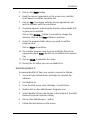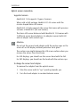
1
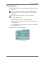
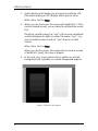
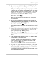
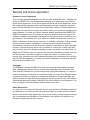
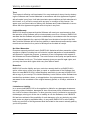
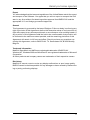
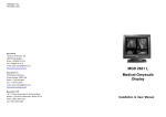
MediCal LE
Installation & User Manual
B410015 - 02
November 2004
www.barco.com
Introduction
Introduction
MediCal LE is a user-friendly and efficient tool for Q/A check and
conformance calibration of medical displays and display systems.
With MediCal LE you can:
•
Perform Q/A checks observing many kinds of test patterns.
See § “Performing quality checks with test patterns”
•
Calibrate the displays with the delivered optical sensor.
See § “Calibrating displays”
•
Select from a list of display functions.
See § “Options”
•
Choose to work calibrated or uncalibrated.
See § “Working uncalibrated”
1
Installation
Installation
MediCal LE installation
Minimum System requirements
•
Color or grayscale imaging board having gamma access
•
Operating system: Windows 2000 Professional,
Windows XP Professional
•
Memory: 64 MByte
•
Free disk space: 15 MByte
Before installing MediCal LE
1.
You must have Administrator privileges to install the
software.
2.
If there are older versions of MediCal LE installed on the PC,
remove them. Please refer to the § “Uninstalling MediCal
LE”, further in this chapter.
3.
Set the resolution (desktop area) of all the displays in your
system to at least 1024x768 (landscape displays) or
768x1024 (portrait displays). Set the resolution by selecting
Start > Settings > Control Panel > Display. Select the Settings
tab and adjust the screen size.
Installing MediCal LE
To install MediCal LE, follow these steps:
2
1.
Exit all open programs.
2.
Insert the CD-ROM containing the MediCal LE installer
program in the CD-ROM drive.
3.
The CD-ROM starts automatically. After a few seconds, the
MediCal LE welcome window appears.
4.
Click on Install. The Setup application starts.
Installation
5.
Click on the Next> button.
6.
Read the License agreement on the screen very carefully.
Scroll down to read the complete text.
7.
Click on Yes if you agree with the License agreement and
wish to continue with the installation.
8.
A window appears, indicating the directory where MediCal LE
is going to be installed.
Click on the Browse... button if you want to change this
directory. Click on the Next> button to continue.
9.
Select the program folder where you wish to add the
program icons.
Click on Next> to continue.
10. The installer program now starts to install the files at the
appropriate place. Note: MediCal LE is installed in the System
Tray
11. Click on Finish to complete the setup.
12. Restart the PC before you can use MediCal LE.
Uninstalling MediCal LE
To remove MediCal LE from your system, proceed as follows:
1.
You must have Administrator privileges to uninstall the
software.
2.
Exit MediCal LE.
3.
From the Start menu, select Settings > Control Panel.
4.
Double-click on the Add/Remove Programs icon.
5.
Select MediCal LE from the list box at the bottom of the Add/
Remove Program Properties dialog.
6.
Click on the Add/Remove... button.
7.
Follow the instructions on the screen.
3
Installation
Optical sensor connection
Supported sensors:
MediCal LE 1.03 supports 2 types of sensors.
When sold as full package, MediCal LE 1.03 comes with the
circular-shaped Barco LCD sensor.
MediCal LE 1.03 also supports the sensor that came with previous
versions of MediCal LE (an oval sensor).
The Barco LCD sensor delivered with MediCal LE 1.03 comes with
2 different sensor head adapters: An adapter covered with felt
and an adapter with suction cups.
Attention:
Do not put the sensor head adapter with the suction cups on the
screen of an LCD display without protective front glass!
The suction cups might damage the LCD screen surface when you
remove the sensor from the screen.
For LCD displays, you should use the sensor head with the felt.
For CRT displays, you should use the head with the suction cups.
To change the sensor head adapter:
To remove the adapter from the optical sensor:
4
1.
Take the sensor with its “eye” pointing towards you.
2.
Turn the head adapter in counterclockwise sense.
Installation
Figure 1: Head adapter removal
3.
Pull the adapter from the sensor.
To apply the head adapter to the sensor:
1.
Take the sensor with its “eye” pointing towards you.
2.
Put the head adapter on the sensor.
3.
Turn the sensor head adapter in clockwise sense.
To connect the sensor:
1.
Put the MediCal LE CD-ROM in the CD-ROM drive. A screen
will appear, but do NOT click on any button.
2.
Plug the sensor in one of the USB connectors of your PC.
3.
Windows pops up a message box "Found new hardware".
4.
Select "Search for a suitable driver for my device
5.
Select to search on the CD-ROM drives to find the proper
drivers.
6.
Click "Next" to install the BarcoView sensor drivers.
5
Installation
To use the sensor:
The Barco LCD sensor, standard delivered with MediCal LE 1.03, is
provided with a metal counterweight around the sensor cable.
Thanks to this counterweight, you can let the sensor cable hang
over the top of the display during calibration or measurement.
Figure 2: Counterweight
Attention:
When using the sensor with the felt-covered head adapter, take
care that no light can enter between the edge of the adapter and
the screen surface.
If necessary, slightly push the sensor to the screen.
6
Starting MediCal LE
Starting MediCal LE
After installing MediCal LE, its icon appears in the System Tray in
the Task Bar.
The icon appears crossed out in case the display(s) are not
calibrated yet. This is the initial situation after installing
MediCal LE
The icon appears without the cross after calibration.
You can start MediCal LE by:
•
Double-clicking on the icon in the System Tray
•
Right-clicking on the icon in the System Tray and selecting
Open MediCal LE.
•
Starting MediCal LE from the Start > Programs > MediCal LE >
menu in Windows.
The MediCal LE main window appears.
Figure 3: Main window
7
Performing quality checks with test patterns
Performing quality checks with test patterns
Introduction
You can display test patterns to perform quality checks. You can
use the patterns for visual checks and for measurements with the
optical sensor.
Note:
In the Options section, you can select which displays in the
system need or need not to be controlled. Test patterns will
appear only on selected displays.
At least one display must be selected .
To display a pre-defined test pattern
1.
Open MediCal LE.
2.
Click on the Test Patterns... button.
3.
Use the Next (>) and Back (<) buttons to scroll through the
possible test patterns.
4.
Double-click on the icon of one of the following patterns:
• SMPTE
• Briggs
• Grid
• Centered square
• Bands with text
• Browse
• Character
• Contrast noise
• Geometry
• Uniformity
8
Performing quality checks with test patterns
To display a custom test pattern
1.
Open MediCal LE.
2.
Click on the Test Patterns... button.
3.
Double-click on the Browse icon.
4.
An explorer-like dialog appears. Browse to the location
where the desired image is stored, select the image, and
click Open.
The selected image will appear.
Pattern options
When you click with the right mouse button while the pattern is
displayed, the pattern options appear:
Inverted:
The imaging board Look-Up Tables are inverted (white becomes
black etc.)
Calibrated:
Disable this option to view the test pattern without the effect of
the calibration. In this way, you can compare the calibrated and
uncalibrated situations.
Enable the option again for normal, calibrated operation.
Quit:
Close the test pattern on this display.
On a system with multiple displays (multi-head system), the
pattern will then appear on the next display.
You can also close the test pattern by left-clicking on the pattern
or by hitting any key on the PC keyboard.
9
Performing quality checks with test patterns
Pre-defined test pattern description
SMPTE
The SMPTE pattern is a universal pattern with which you can
check geometry, focus, white luminance, bandwidth and display
curve.
We suggest to check on display curve. Therefore, check the
patches with the 5% gray square on black and the 95% white
square on white. The gray squares should be visible if the system
is calibrated according to the DICOM display function.
To measure the patches, put the optical sensor on a patch and
check the measured luminance displayed in the Measure
window.
Briggs
This pattern can be used to check if the display function is
perceptually linear (calibrated according to the DICOM display
curve). The pattern consists of rectangles including small squares
that are 5% darker.
The small squares in each of the rectangles should be visible if
the system is calibrated according to the DICOM display function.
Grid
This pattern can be used to check the image geometry (size,
position, linearity) and focus.
Check if the lines of the pattern are:
10
•
straight
•
at an equal distance apart
•
sharp
Performing quality checks with test patterns
Centered Square
This pattern can be used to check the white luminance.
Put the optical sensor on the white square and check the
measured luminance displayed in the Measure window.
Bands with text
This pattern can be used to check if the display function is
perceptually linear (calibrated according to the DICOM display
curve).
This is the case if the text in all of the bands is legible.
Browse
Browse and select your own test pattern. MediCal LE supports
bmp, tif, jpg and gif files.
Character
This pattern can be used to check the image focus.
Check that the characters are sharp.
Contrast noise
This pattern can be used to check the video signal.
Check that there is no ghosting or smearing near the white
squares.
Geometry
This pattern can be used to check the image geometry, especially
linearity.
For linearity, check if the circles on the pattern are well-shaped
and symmetrical.
11
Performing quality checks with test patterns
Uniformity
This pattern can be used to check if the white and black levels
are uniform all over the screen. Therefore, put the sensor on the
different patches on the screen, and check the Measure window
to see if the measured value is approximately the same all over
the screen.
Note:
To see what the correction in MediCal LE does to your image, it
may be a good idea to compare the SMPTE or Briggs pattern with
the correction enabled and disabled. You can do this by clicking
the right mouse button on the pattern and disabling the
Calibrated option.
12
Calibrating displays
Calibrating displays
Note:
In the Options section, you can select which displays in the
system need or need not to be controlled. Calibration is possible
only on selected displays.
At least one display must be selected.
To calibrate displays:
1.
Be sure to connect the optical sensor to the PC USB connector
or a USB hub.
2.
The Found New Hardware wizard may appear, asking you to
search for a suitable driver.
You can find the sensor drivers on the MediCal LE CD-ROM.
For more information, see § ““Optical sensor connection””.
3.
When done, open MediCal LE.
4.
If necessary, click on the Options button to:
• exclude displays from calibration
• select the display function to which to calibrate the
displays
When done, click on Back to return to the main window.
For more information, see § “Options”.
5.
Click on the Calibrate button.
6.
If you have a system with more than 1 display connected, a
window appears asking if you wish to calibrate this display.
Select Yes and click on the Next button.
If you have just 1 display connected, the calibration starts
immediately (see the following step).
13
Calibrating displays
7.
Select what kind of display you are going to calibrate: LCD
(flat panel display) or CRT (display with a picture tube).
When done, click on Next.
8.
When you use the sensor that came with MediCal LE 1.03 (a
circular-shaped sensor), you are asked to calibrate the sensor
first.
Therefore, carefully cover the “eye” of the sensor completely
so that absolutely no light can enter the sensor “eye”. E.g.,
you can hold the sensor with its “eye” down on a table
surface.
When done, click on Next.
When you use the sensor that came with a previous version
of MediCal LE (oval), this step is skipped.
9.
In the next step, a test pattern with 4 patches on a black
background and 4 patches on a white background appears.
Figure 4: Calibration test pattern
14
Calibrating displays
10. When you have selected to calibrate an “LCD” display, check
if geometry and phase are well-aligned.
If they are well-aligned, the image is clear, crisp and stable.
If they are not well-aligned, the image will show dark bands
and/or vibrations, especially in the gray border of the image.
In that case, align display geometry and phase until the
image is crisp and stable (see “Notes:” below).
When done, click on Next.
When you have selected to calibrate a “CRT” display, this
step is skipped.
11. Set the display brightness to minimum. Then increase the
brightness until you can just distinguish all 4 patches on the
black background (see “Notes:” below).
When done, click on the Next button.
In this way, you have determined the black luminance target
value.
12. Now set the display contrast to maximum. Then decrease the
contrast until you can just distinguish all 4 patches on the
white background (see “Notes:” below).
When done, click on the Next button.
In this way you have determined the white luminance target
value.
13. If the selected display function is DICOM, the ambient light
compensation is determined now.
Therefore, hold the sensor approximately 5 cm (2 inches)
from the screen surface, as shown on the screen image.
Then, click on the Next button.
Hold the sensor like this until the next message appears.
14. An image of a sensor measuring head appears in the center
of the image. Hold the optical sensor on the white patch on
the screen until the end of the procedure.
This may take about half a minute. Do not remove the sensor
during this calibration period.
15
Calibrating displays
15. When the calibration is finished successfully, the Calibration
Successful message appears and a 'happy' sound is played.
16. Click on the Finish button. The Calibration Wizard will start on
the next display, in case of a multi-head system.
Notes:
•
If you use a digital (DVI) video signal connection, the
adjustments for brightness, contrast, geometry and phase
may not be present in your display.
•
Some LCD displays provide automatic adjustments for
geometry and phase (e.g., auto-geometry, auto-phase etc.).
You can use these automatic adjustments for geometry and
phase adjustment during calibration (see step 10.)
16
Options
Options
1.
Open MediCal LE.
2.
Click on the Options button.
3.
Select the display function for all displays of the system.
We recommend to select DICOM in almost any medical
application. The DICOM curve, if calibrated, ensures that you
can distinguish the highest possible number of gray levels.
Select CIE if you need to comply to the DIN or IEC standard.
Select Gamma to calibrate to a gamma 2.2 function.
Click on the Next button.
4.
Select the units in which you want all luminance values and
measurements to be expressed: cd/m² (Candela per square
meter) or fl (Footlambert).
Note: Cd/m² is a metric unit and is synonymous with "nit".
Click on the Next button.
5.
On a multihead system, a graphical representation of the
system appears. The rectangles in the “Select displays to be
controlled” window represent the display controller heads in
the system and the displays connected to them.
By default, all the displays are selected (showing a check
mark in the corresponding rectangle). To deselect displays
(meaning they will not be calibrated nor controlled), click the
corresponding rectangles. As a result, a cross appears in
these rectangles.
6.
If you want all displays from the system to have the same
black and white reference values after calibration, check the
Equalize after Calibration option (multihead systems only).
7.
Click on the Finish button to enter the selected options.
To cancel any changes made to the options, click on the Back
button to return to the main window.
17
Working uncalibrated
Working uncalibrated
You can ignore the corrections you have performed on the
display system with MediCal LE.
Therefore, right-click on the MediCal LE icon in the Windows Task
Bar (the MediCal LE application must be closed).
Select Disable Calibration. The selected menu item changes to
"Enable calibration".
To activate the corrections again, select Enable calibration.
18
Troubleshooting
Troubleshooting
The following problems may occur:
The sensor is connected, but the system does not find it
This may be the case when you unplugged the sensor, and
plugged back in while MediCal LE resided in the system tray.
Solve this by rebooting your computer.
Display window or test patterns appear dithered
Ensure that the selected color palette in the display properties is
set to True Color.
Solve this by selecting a True Color palette.
Patterns or calibration does not appear on all displays of the system
•
You may have added displays to your system while the
MediCal LE window was still open.
Close the application window and restart MediCal LE.
•
You may have deselected displays in the Options section.
Patterns or calibration has disappeared
•
Probably you have one or more imaging boards in your PC to
which no display is connected, while the board is still
activated in the display properties control panel.
Another possibility is that you have a multi-head imaging
board in the PC, while one of the heads is not connected to a
display.
De-activate these imaging board heads in the control panel
or connect a display to them.
•
You may have deselected displays in the Options section.
19
Glossary
Glossary
Frequently-used terms:
Calibration
In many cases, calibration is the remedy for a display that is no
longer conform to its target working point, which is defined by
the black and white luminance and the display function.
The calibration routine restores the black luminance, the white
luminance and the display function.
Calibrating a display results in changing the PC imaging board's
LUT.
Display Function
A Display Function describes how a display device converts the
voltages at the inputs into light.
In the context of a medical viewing station, a display device is
the combination of imaging board and display.
The display function is a graph that shows how the light from the
picture tube evolves from minimum to maximum luminance
while the data levels at the input of the imaging board go from 0
to maximum.
Gamma
The Gamma function is a kind of display function, characterizing
an apparatus that converts voltages into light or ink or vice versa.
Displays, printers, scanners, ... all have their own, unique Gamma
function.
In a display, this function is exponential. The Gamma value is the
exponent that determines the shape of the function.
20
Glossary
Gamma 2.2
This is a gamma function with a gamma value of 2.2, which is
approximately the natural gamma of most CRT displays.
Imaging board head
An imaging board or graphics board converts the digital data
from the computer into analog video voltages.
Most of the common imaging boards contain just one set of
video and sync outputs. However, some high-end boards, like
some of the BarcoMed boards, contain two sets of video and sync
outputs. This is called a dual head imaging board. It is like two
complete imaging boards implemented on one single unit.
A dual head board in the computer behaves exactly as if two
separate boards were installed.
DICOM
DICOM stands for Digital Imaging and Communications in
Medicine. It is a standard developed by the American College of
Radiology (ACR) and the National Electrical Manufacturers
Association (NEMA).
The standard specifies how digital image data can be moved
from system to system.
In addition, Supplement 28 Part 14 specifies a function that
relates pixel values to displayed Luminance levels and is called
Grayscale Display Function Standard.
CIE
CIE stands for Commission Internationale d'éclairage
(International commission on illumination), an organization
devoted to international cooperation and exchange of
information on all matters relating to the science and art of
lighting.
The CIE display curve in MediCal LE is based on the CIE 1976
standard.
21
About MediCal LE
About MediCal LE
MediCal LE 1.03 version
Copyright © 2001-2004 BARCO nv. All rights reserved.
More information?
http://www.barco.com/medical/
22
Warranty and License Agreement
Warranty and License Agreement
Software License Agreement
This is a legal Agreement between you, the end user, and BARCO NV., a Belgian corporation (“BARCO NV”). By accepting this package, you agree to be bound by the
terms of this Agreement. If you do not agree with the terms of this Agreement, return
the unopened disk package and the accompanying manuals, containers, and hardware (“Product Materials”) to the person or place from which you obtained them for a
full refund. Your product is a single user version unless your product’s packaging indicates otherwise, or unless you have a separate written Agreement with BARCO NV.
BARCO NV grants to you a nonexclusive license to install and use one copy of the
software included in this package (“Software”) on a single terminal connected to a single computer. The Software is in “use” when it is loaded into temporary memory (i.e.
RAM), or installed into permanent memory (i.e. hard disk, CD-ROM, or other storage
device) of that computer. Installation on a computer that may be concurrently
accessed by more than one user shall not constitute a permitted use and a separate
license is required for each active user connected to a computer on which the Software is being used. If the Software package contains more than one type of disk (i.e.
floppy and CD-ROM), then you may use only one set of the disks provided. You may
not use the disks on another computer, or loan, rent, lease, or transfer them to
another user except as part of the permanent transfer (as provided below) of all Software and Product Materials. You may only use the Software in conjunction with Software licenses by BARCO NV.
Copyright
The Software is owned by BARCO NV and is protected by international copyright
laws, international treaty provisions, and all other applicable laws. Therefore, you
must treat the Software like you would any other copyrighted material (i.e. a book or
musical recording), except that you may either make one copy of the Software solely
for backup or archival purposes, or transfer the Software to a single hard disk, provided you keep the original solely for backup or archival purposes. Any such backup
automatically becomes property of BARCO NV and is subject to this Agreement. You
may not copy the Product Materials without written permission.
Other Restrictions
You may not rent or lease the Software, but you may transfer the Software and Product Materials on a permanent basis provided you retain no copies, and the recipient
agrees to the terms of this Agreement. You may not modify, reverse-engineer, decompile, or disassemble the Software. If the Software is an update, any transfer must
include the update and all prior versions.
23
Warranty and License Agreement
Term
This license is effective until terminated. You may terminate it at any time by destroying the Software and Product Materials in accordance with this Agreement together
with all copies in any form. It will also terminate upon conditions set forth elsewhere in
this license, or if you fail to comply with any term or condition of this license. You
agree upon such termination to destroy the Software and Product Materials in accordance with this Agreement together with all copies in any form.
Limited Warranty
BARCO NV does not warrant that the Software will meet your requirements or that
the operation of the Software will be uninterrupted or error-free. However, BARCO NV
warrants that the Software will perform substantially in accordance with the accompanying Product Materials for a period of 90 days from the date of receipt of the Software, and the Software will be free from defects in materials and workmanship under
normal use and service for a period of 90 days from the date of receipt.
No Other Warranties
Except as expressly set forth herein, BARCO NV disclaims all other warranties, either
express or implied, including but not limited to implied warranties of merchantability
and fitness for a particular purpose, or warranty of non-infringement with respect to
the Software and Product Materials. The entire risk as to the quality and performance
of the Software is with you. This limited warranty gives you specific legal rights, and
you may also have other rights which vary from state to state.
Remedies
BARCO NV’s entire liability and your exclusive remedy shall be, at BARCO NV’s
option, either return of the price paid, or repair or replacement of the Software that
does not meet BARCO NV’s Limited Warranty and which is returned to BARCO NV
with a copy of your receipt. This Limited Warranty is void if failure of the Software has
resulted from accident, abuse, or misapplication. Any replacement product will be
warranted for the remainder of the original warranty period, or 30 days, whichever is
longer.
Limitation on Liability
In no event shall BARCO NV or its suppliers be liable for any damages whatsoever
including, without limitation, damages for loss of business profits, business interruption, loss of business information, or other pecuniary loss or incidental or consequential damages, arising out of the use or inability to use the Software, even if BARCO
NV has been advised of the possibility of such damages; or for any claim by any other
party under any legal or equitable theory. In any case, BARCO NV’s entire liability
under any provision of this Agreement shall be limited to the amount actually paid by
you for the product.
24
Warranty and License Agreement
Export
You acknowledge that the laws and regulations of the United States restrict the export
and reexport of the Software. You agree that you will not export or reexport the Software in any form without first obtaining written approval from BARCO NV and the
appropriate U.S. and foreign government approvals.
General
This Agreement is governed by the laws of Belgium. Failure or delay in enforcing any
right or provision of this Agreement shall not be deemed a waiver of such provision or
right with respect to any subsequent breach or a continuance of an existing breach. If
any provision of this Agreement shall be held to be unenforceable, that provision will
be enforced to the maximum extent possible, and the remaining provisions of this
Agreement will remain in full force and effect. Should you have any questions concerning this Agreement, write to BARCO NV. Th. Sevenslaan 106, B-8500 Kortrijk,
Belgium.
Trademark information
MediCal, BarcoMed, and MeDis are registered trademarks of BARCO NV.
Windows NT, Windows 2000 and Windows XP are registered trademarks of Microsoft
Corporation.
All other products and company names are trademarks of their respective owners.
Disclaimer:
MediCal LE cannot correct or solve any display malfunctions or poor image quality.
BARCO cannot be held responsible for any damages or harm caused by malfunctioning or poorly performing displays.
25