1
ELECRAFT KXAT1 AUTOMATIC ANTENNA TUNER
Assembly and Operating Instructions
Revision A, Oct. 14, 2003. Copyright © 2003, Elecraft; All Rights Reserved
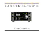
Introduction
The KXAT1 internal automatic antenna tuner (ATU) allows random-length, end-fed wire antennas to be
connected directly to the Elecraft KX1 transceiver and used on one or more bands. It can be also be used
with most coax-fed antennas, or with balanced feedlines via a balun. Like our KAT1, KAT2, and KAT100
auto-tuners, the KXAT1 functions on receive as well as transmit. This provides an increase in receive
sensitivity and improves rejection of out-of-band signals.
The KXAT1 uses latching relays to reduce current drain to nearly zero except when tuning. These relays
select appropriate combinations of inductance and capacitance, as well as either a capacitor-in or capacitorout L-network configuration. Tune-up is controlled by the KXAT1's microprocessor, which also supplies
SWR and power information to be displayed on the KX1's 3-digit LED display. Once a match has been
found, matching parameters are saved so that the settings can be recalled immediately on any band change.
ATU parameters (L, C, SWR, etc.) can be viewed using the KX1’s AT U menu entry. Additional settings
are provided to perform component-level troubleshooting of all relays and L-network components.
In addition to being one of the world’s smallest automatic antenna tuners, the KXAT1 is very easy to build
and install. The KXAT1 module plugs directly into the KX1’s main board with no additional wiring. Gold
plated connectors and redundant connector pins are used to provide excellent reliability for field operation.
Specifications
L/C Ranges
Network Type
Tuning time
SWR Display
Current Drain
Size
Weight
L (inductance): 0-4.5 µH in 7 steps; C (capacitance): 0-140 pF in 7 steps
L-network (series L, shunt C); C switchable to transceiver or antenna side
1 to 3 seconds typical for initial tune-up; < 1/2 sec. to recall per-band settings
1.0:1 to 9.9:1
Approx. 10-30 mA during TUNE; < 1 mA at all other times
4.8" (L) x 1.0" (D) x 0.5" (H) (12.2 x 2.5 x 1.3 cm)
1 oz.
i
Caution: Some components in this kit can be damaged by static discharge. Before
handling any transistors or integrated circuits, always put on an anti-static wrist strap or
touch any grounded, unpainted metal surface.
1
Parts Inventory
The table below lists all parts in the kit. The KX1 Owner's manual has photographs of similar parts.
Ref.
C1
C2
C3
C4-C8,C11
C10
C9
D1,D2
K1-K7
L1,2,3
P1
P2
P3
R1,R2
R3
R4
RFC1
T1
U1
Z1
MISC
MISC
MISC
MISC
MISC
MISC
Description
Capacitor, 20 or 22 pF ("20," "22," "200," or "220")
Capacitor, 39 pF ("39" or "390")
Capacitor, 82 pF ("82" or "820")
Capacitor, .01 µF ("103")
Capacitor, 100 pF, 200 V, NPO disc ("101")
Capacitor, 1-40 pF trimmer
Diode, 1N5711
Relay, DPDT
T37-2 toroid core, red, 0.37" diameter
(L1=0.64 µH,12T; L2=1.3 µH, 17T; L3 = 2.6 µH, 25 T)
Connector, 3 pin male, 0.1" spcg
Connector, 2 pin male, 0.1" spcg
Connector, 5 pin male, 0.1" spcg
Potentiometer, 100 k trimmer, low-profile
Resistor, 200 ohms, 1/4-W, 5% (red-black-brown)
Resistor, 3.3 k, 1/4-W, 5% (orange-orange-red)
Miniature RF choke, 15 µH (brown-green-black)
Transformer on FT37-43 core, 10 turns bifilar (see text)
MCU, KXAT1, PIC16C716
Ceramic resonator, 4.0MHz +/- 0.2%
KXAT1 PC board (part of KX1 PC board set)
Enamel wire, #26 red
Enamel wire, #26 green
Solid, insulated hookup wire, green
Socket for U1, 18 pins
Foot, self-adhesive (spacer between ATU/bottom cover)
Qty
1
1
1
6
1
1
2
7
3
Part No.
E530017
E530036
E530038
E530019
E530034
E540002
E560004
E640010
E680006
1
1
1
2
1
1
1
1
1
1
1
5 ft.
2 ft.
1 ft.
1
1
E620071
E620072
E620073
E520012
E500020
E500017
E690012
E680003
E610016
E660001
E100175
E760002
E760004
E760008
E620031
E700024
Parts Placement Drawings
Parts placement drawings for both sides of the KXAT1 PC board can be found in Appendix F of the KX1
manual.
2
Assembly
i
A fine-point, temperature-controlled soldering iron (700-800 degrees F) is required to assemble
this kit. A high-wattage iron or one with a wide tip may damage components, pads, or traces. Use a
minimum amount of solder to avoid ground shorts.
i
All parts are installed on the top side of the board except as noted (the side with the relays, toroids,
and microcontroller U1). Double-check all values before soldering, since removing parts from double-sided
PC boards can be difficult.
Place relays at locations K1-K7 as shown by their component outlines. Do not solder yet. Do not
bend the relay leads.
Using a flat object to hold K1-K7 in place, flip the board over. Solder just one inner pin on each relay.
Inspect the relays closely to make sure that they’re seated flat against the PC board. If not, re-heat the
soldered pin while pressing down on the relay. Once all relays are properly seated, solder all pins.
Trim the relay leads as short as possible to provide clearance for folded capacitors in a later step.
Install the IC socket at U1. Align the socket's notched end with the notch in the component outline.
On the bottom side, install R3 (200 ohms, red-black-brown) and R4 (3.3 k, orange-orange-red).
Install D1 and D2, with the banded end of each diode oriented as shown on the board.
Install ceramic resonator Z1, which looks like a capacitor with three leads. It can be installed in either
of two orientations. Keep soldering time to 2-3 seconds per lead to avoid overheating the part, which can
alter its frequency. Trim the leads after soldering.
Install trimmers R1 and R2 on the bottom side. Make sure they are seated flat against the PC board.
Install RF choke RFC1 (brown-green-black). The leads are fragile—handle carefully.
Install the trimmer capacitor, C9, on the bottom side. The flat side should be oriented as shown by the
component outline, and the trimmer must be seated flat against the board.
Install the capacitors listed below on the bottom side of the board, but don't solder them yet. Leave the
leads about 0.1" long so the capacitors can be folded down in the next step. All possible value markings are
shown in parentheses.
__ C1, 20 or 22 pF (20, 22, 200, or 220)
__C3, 82 pF (82 or 820)
__ C2, 39 pF (39 or 390)
__ C10, 100 pF (101)
3
Fold down C1, C2, and C3 at about a 45-degree angle, but not so far that they contact the nearby relay
pins. C1 should be folded toward K1, C2 toward K4, and C3 toward K2.
Solder C1-C3 and C10 from the bottom side to avoid damaging the relays. Trim the leads on the top.
i
In the following step, the installed height of the capacitors must be no more than 5/16" (7.5 mm).
The leads may be pre-formed so that the capacitors sit a small distance above the board. As long as the
installed height is below the limit specified, there's no need to straighten the leads.
Install the .01-µF capacitors ("103") on the top side of the board (C6, C4, C5, C7, C8, C11). They
should be seated as far down onto the board as possible (see above).
i
In the following steps, inductors L1 through L3 will be wound and installed. There is no need to
adjust the windings to precisely match the inductances shown on the schematic.
Inductor L1 is wound on a T37-2 core (red) using 8" (20 cm) of #26 red enamel wire. To wind the
inductor, pass the long end of the wire through the core exactly 12 times. Each pass through the core
counts as one turn. The finished winding should look like the illustration below. Exact turns spacing is not
critical.
Remove insulation
Spread out the turns of L1 so they occupy about 80-90% of the core’s circumference.
Cut L1's leads to about 1/2" (12 mm) long. Completely remove the enamel insulation from the leads
to within 1/8” (3 mm) of the core. The enamel wire provided can be heat-stripped using a small amount of
solder on the tip of your iron. Stripping using this method takes 4-6 seconds.
4
Install L1 vertically on the PC board as shown by its component outline, then pull the leads taut on
the bottom of the board.
Trim and solder the leads of L1. When soldering, make sure that the solder binds well to the leads. If
the lead appears to be an "island" in a small pool of solder, chances are it is not making good contact.
Measure from pad to pad using an ohmmeter to verify the connection (low resistance).
Wind and install L2 and L3 using the same procedure you used for L1. The number of turns and wire
length for each inductor is shown below.
__ L2, 17 turns (11" [28 cm])
__ L3, 25 turns (15" [38 cm])
Fold C10 down toward K6 and L3, but not so far that it touches the leads of these components.
T1 is wound on a ferrite toroidal core (gray, FT37-43; may have an orange dot). Cut two 10" (25 cm)
lengths of #26 enamel wire, one red and one green. Inspect the wires closely to make sure the enamel
coating is not chipped or broken.
Twist the two wires together, crossing over each other about 3 to 4 times per inch (1-2 times per cm).
Wind the twisted wires onto the core as shown below, using 10 turns. Each pass through the core
counts as one turn, and turns spacing should closely resemble the illustration.
i
As shown below, the wires labeled (1) and (3) should originate from below the core, and
wires (2) and (4) from above it. This will ensure that the transformer has the correct phasing.
4 (RED)
2 (GRN)
1 (GRN)
3 (RED)
Trim the leads of T1 to about 1/2" (12 mm) long. Then completely remove the insulation from T1's
leads up to the edge of the core, using a solder pot, hot soldering iron tip, sand paper, or by scraping with
an X-acto knife. Do not attempt to burn off the insulation using a match or lighter, as the flame may
fuse the pairs of wire together, causing them to become shorted.
5
Tin T1's leads with solder. If the leads do not tin easily, the insulation may not be fully removed.
Using an ohmmeter, measure between the red and green wires to make sure that they're not shorted.
Install T1 as indicated by its PC board outline. Insert the leads into the numbered holes as identified
by the drawing on the previous page.
Pull the leads taut on the bottom of the board. Before soldering, make sure that the entire portion of
exposed lead is properly tinned.
Cut a 1-1/8" (2.9 cm) length of insulated, solid-conductor hookup wire. Remove 1/4" (6 mm) of
insulation from each end. This jumper will form the 1-turn link winding of T1.
Insert this wire through the center of T1 and into the pad labeled 5. Bend the wire down to the left and
insert the other end into pad 6. Pull the leads of the wire taut on the bottom of the board, then solder.
Install the self-adhesive foot in the location identified on the ATU module ("FOOT").
Touch a grounded, unpainted metal surface before handling the microcontroller (U1, 16C716).
Carefully straighten U1's pins, then insert U1 into its socket. Be sure to orient the notched end of U1 toward
the pin 1 label.
Remove the bottom cover from the KX1 transceiver (2 thumbscrews) and turn it upside-down with
the BNC connector on the left. On the KX1 PC board, locate J8 (2 pins), J7 (3 pins), and J6 (5 pins).
Remove the jumper installed between pins 1 and 3 of J7 (ATU bypass).
The KXAT1 kit includes mating male connectors for J8, J7, and J6, designated P2, P1, and P3,
respectively. Insert these connectors (the long ends) as far as they'll go into their respective female
connectors on the KX1 board. P1-P3 must be fully seated, or the bottom cover will not fit properly with
the ATU installed.
Place the KXAT1 module onto the pins of P1-P3. Verify that the module is resting flat against the
plastic bodies of the three connectors, and is not touching any parts on the KX1 board. If necessary, adjust
the positions of toroids and capacitors on the two boards to allow them to fit together without obstruction.
Press down on the KXAT1 at both ends to ensure that P1-P3 are fully inserted into J6-J8. Then solder
all pins of P1-P3.
Trimmer R4 on the KX1 board is accessible through a hole in the ATU board (as well as a
corresponding hole in the bottom cover). We recommend doing ATU alignment and test with R4 fully
clockwise (maximum power output, about 4 watts at 12-13V). R4 can be adjusted using a small flat-blade
screwdriver.
This completes KXAT1 assembly. Keep the bottom cover off for the alignment and test steps which follow.
6
Alignment and Test
Connect a power supply or battery to the KX1 and turn on power.
Tap M E NU and scroll through the entries until you find AT U. To select the mode for the ATU, hold
E DI T . If you see three dashes (- - - ) instead of the AT U parameter, refer to Troubleshooting.
Using the VFO knob, set the AT U parameter to the first relay test setting, L 0 . You should hear a
relay switch when you move to L 1 , then to L 2 , and finally to L 3 . The same should be true for C0
through C3 , as well as N1 and N2 . (If you don't hear any relays switching, see Troubleshooting.) Exit the
menu.
Select 40 meters using the KX1's B AND switch.
Connect a 50-ohm dummy load to the KX1’s antenna jack (5W or higher rating).
Set the AT U parameter to CAL using the menu.
Pre-set potentiometers R1 and R2 on the bottom of the ATU board to exactly their mid-points.
Touch the (+) lead of a digital multimeter (DMM) or analog voltmeter to the small hole near the
"REFL" label on the bottom of the KXAT1 board. Connect the (-) lead to one of the KX1's long standoffs.
Set the voltmeter for 2 or 3 DC volts full scale.
Locate a non-metallic tuning tool for adjusting ceramic trimmer C9. You can use a small flat-blade
screwdriver or jeweler’s driver with tape wrapped around the metal shaft to prevent you from contacting it.
Enter TUNE mode by holding M E NU and B AND together (the KX1 will display forward power,
e.g. P4 . 0 ). Adjust C9 for the lowest possible voltmeter reading—the null may be sharp. Cancel TUNE
mode by tapping any switch (the KX1 will display SWR, e.g. r1 . 0 ).
If your voltmeter has a lower scale than 2 or 3 V, set it for this scale, and repeat the previous step.
Optional Power Calibration: The KXAT1 will provide acceptable power-reading accuracy with R1 and
R2 set to exactly their mid-points. More accurate adjustment requires a calibrated wattmeter:
Connect a known-accurate wattmeter between the KX1 and a 50-ohm dummy load.
Enter TUNE mode. Adjust R1 (FWD) on the KXAT1 so that the KX1’s power display agrees with the
wattmeter. Tap any switch to exit TUNE. The SWR display should show r1 . 0 . If it doesn't, chances are
your dummy load is not 50 ohms, or the null adjustment (C9) was not done correctly.
Adjust R2’s rotation to match that of R1 (visually).
Installing the Bottom Cover
Turn off the KX1 and re-install the bottom cover. Be very careful not to pinch the battery wires
between the bottom cover and the ATU module or the nearby long standoff.
7
Using The ATU
Basic ATU Operation
• Connect the best possible antenna and ground to the KX1 (see Antenna Considerations).
• Use the KX1 menu to set the ATU’s operating mode to T UN (auto-tune), then exit the menu.
• Enter TUNE mode (M E NU + B AND ). AT U will be displayed for a few seconds while the tuner
finds the best match (if you don't hear any relays, the SWR was already low). Power will then
be displayed (e.g. P4 . 0 ). Tap any switch to cancel TUNE; the SWR will be displayed (e.g. r1 . 0 ).
• With the ATU installed, the LED bargraph will show power output while keying (0.5 watts per bar).
• ATU settings are stored in EEPROM, and will be recalled instantly whenever you change bands.
Displaying Power Output and SWR while preserving matched L and C settings
If you change the AT U setting to rX. X (SWR) in the menu, L and C settings will not be changed during
TUNE mode, even if the SWR is high. This setting is rarely needed; T UN mode is recommended.
Using an External Antenna Tuner
If you're using an external antenna tuner, bypass the KXAT1 by setting AT U to CAL . Power and SWR
will still be displayed in TUNE mode. Note: The KXAT1 cannot display SWR continuously during TUNE,
so an external tuner with built-in SWR bridge is recommended. Most stand-alone tuners include a bridge.
Important ATU Operating Tips
• A 1.0:1 SWR is not necessary for good performance. However, a low SWR will help protect
the transmitter. See Antenna Considerations.
• If you switch to BAT (battery) display mode, then enter TUNE, you'll see the transmit-mode battery
voltage, not SWR or power output. The ATU settings will not change. If the indicated battery voltage
drops too far on transmit, the battery should be recharged or replaced.
ATU Menu Settings
Table 1 lists all of the AT U menu settings. T UN is used for normal operation, and the tuner is bypassed
when set to CAL . Other settings are primarily used for troubleshooting.
Table 1. ATU Modes
Mode
Description
Mode
Description
CAL
Calibration/Bypass, L and C = 0
Exx
1-49 = error (see Troubleshooting)
TUN
Auto-tune mode
Fx.x
KXAT1 firmware revision, e.g. F1.0
rx.x
SWR from most recent TUNE
L0-L3
Individual inductor test (C = 0)
Lx.x
Inductance, µH
C0-C3
Individual capacitor test (L = 1 µH)
C.xx
Capacitance, nF (.01 nF = 10 pF)
N1
Network relay test, Cin (L/C = 0)
NTx
Network type; 1=Cin, 2=Cout
N2
Network relay test, Cout (L/C = 0)
8
Antenna Considerations
The KXAT1 will work with coax-fed dipoles, verticals, etc., but it's optimized for use with random-length
wire antennas. These are often the easiest antennas to set up in the field. However, certain wire lengths
must be avoided, and ground radials are required (both issues are discussed below). You should test your
chosen antenna system ahead of time, if possible, to be sure the KXAT1 can achieve an acceptable match.
No-feedline operation: At QRP power levels, feedline is not always necessary. In many cases you can
connect a wire antenna directly to the KX1 and toss it into a tree, then lay out at least one ground radial, as
shown below. This antenna can be set up quickly, and compares favorably to a low, coax-fed dipole or
inverted V. It also minimizes station weight (see further details on wire and accessories on page 10). If you
toss the wire into a tree, try to keep all but about one foot of wire exposed. A wire that is mostly in a tree
will still radiate, but not as well.
Wire antenna length: Since the KX1 can only match a moderate range of impedances, a given random
wire length is not guaranteed to provide an acceptable match on all three bands. Results will vary
depending on the wire length, height, type of support, and ground system. But for backpacking use on
40/30/20 meters, a wire length of 24-28 feet will generally provide good results. For use on 30/20 m only,
as little as 12 ft. can be used, and for 20 m only, as little as 8 ft. Avoid lengths which are close to a halfwavelength long or any multiple thereof, which will be out of the KXAT1's matching range. For example,
you should avoid using close to 33' if 20 m operation is planned, or 46' if you'll be using 30 m.
Ground system: Use a at least one ground radial, cut to at least 1/8th wavelength on the lowest band used
(16' on 40 meters). When possible, use two or more radials, with one cut to 1/4 wavelength on each band.
9
Backpacking Verticals: The KXAT1 may improve the match to a backpacking-style vertical. If the
antenna has a loading coil, you should first adjust it for minimum SWR, since such antennas can be very
narrow-banded. Set the AT U menu entry to CAL mode (bypass) for this purpose, then back to T UN
mode to further match the antenna using the KXAT1 (if necessary).
Whip Antennas: Short whip antennas connected directly to the KX1 may damage the antenna jack or PC
board, and so should only be used in an emergency. They are also very poor radiators.
Do I Need a really low SWR? Not necessarily. For example, if the SWR is 2:1, the loss in transmitted
signal strength will be only about 0.5 dB. However, a low SWR will protect the transmitter, and an SWR
under 2:1 is recommended. The KXAT1 always tries to hit 1:1, and with most antennas it will find an SWR
below 1.5:1 on most bands. If the SWR is higher than 2:1 after matching, try using a balun or reconfiguring
the antenna or changing its length.
Using Baluns: A balun can improve the match to very high-impedance antennas, allow the KXAT1 to be
used with balanced line, and help isolate the antenna from the rig to reduce RF pickup. A low-loss, broadband, 4:1 balun such as the Elecraft BL1 is a good choice(it's also quite small—just 1.5 x 3").
Suggested Wire and Accessories
Wire: #26 stranded copperclad steel wire, such as Wireman #541 (also available from Davis RF as
#WM541), is strong, lightweight, and easy to keep straight. A 25-ft. length weighs less than half an ounce.
Adapters: To go from BNC directly to wires, you'll need an adapter. The smallest suitable adapter is the
Pomona model 3430-2, which is a single binding post to BNC male (see drawing below).
If you use this adapter type, you'll need to use one of the KX1's thumbscrews as a ground tie-point,
requiring that you carefully remove some paint from around the bottom cover holes on both inside and
outside. A larger but more versatile adapter is the Pomona model 1296. This is a double binding post to
BNC male, which provides both antenna and ground connections. The more expensive model 3296 also
has double binding posts, but they're the miniature type, reducing overall dimensions.
Weights: A large, stainless steel hex machine nut, thread diameter 5/8", can be found at hardware stores
and works well for tossing wires into trees (weight: about 1 oz.). If you prefer fishing weights, avoid using
lead, which is toxic to wildlife. Stainless steel weights are available (e.g., www.bulletweights.com1).
Supporting hardware: End insulators and non-conductive support line are not strictly necessary for lowpower portable antenna installations. In general, you can simply attach a weight to the end of the wire itself.
But if you prefer to isolate the end of the wire to minimize interaction with other objects, you can fabricate
lightweight insulators from small pieces of plastic. Small-diameter nylon cord can be used for support lines.
1
Additional suppliers can be found with a web search for "non-toxic weights" or "non-toxic fishing tackle."
10
Troubleshooting
If the ATU menu parameter shows "- - - " at all times, look for a connector shifted by one position, an
unsoldered pin, U1 installed backwards on the ATU board, or a defective U1. Also check the ATU PC
board for shorts to ground, solder bridges, and unsoldered
If the ATU menu parameter becomes "- - - " after doing a tune-up, it may be due to very high RF
feedback into the transceiver. Turn power off and back on, then re-test the ATU using a dummy load or a
different antenna. If it functions correctly on a dummy load but not on your antenna, try using a balun.
If the SWR isn’t < r1 . 2 with a 50-ohm load, C9's setting may be incorrect.
If the power indicated is always about 0 watts, the windings of T1 may be reversed, or one or more leads
of T1 or L1-L4 may not be properly stripped.
If the ATU shows an error message (Ex x in the menu where x x is between 1 and 49), you may have a
defective microcontroller (KXAT1-U1). Ex x numbers 50-99 are used for tune-up algorithm tracking, and
do not indicate a problem.
If SWR is not displayed after exiting TUNE, you may have high RF feedback into the transceiver. You
may need to improve your ground system, move the antenna farther away, or use a balun.
If the tuner is unable to achieve a low SWR on some bands, even with several different antennas, you
could have a single defective relay or component on the L-C board. Start by slowly scrolling through ATU
menu parameters L 0 through L 3 , C0 through C3 , N1 , and N2 . These are intended for relay testing. For
example, L 0 turns off all of the inductor relays (K4-K6). L 1 turns on K4, etc. Similarly, C0 turns off all
of the capacitor relays, and C1 turns on K1. N1 and N2 place the network configuration relay, K7, into its
two positions: CTX (C-in L-network) or CANT (C-out L-network).
If the relays are all working but you suspect an inductor or capacitor, you can test each L and C by
noting their effect on SWR, one at a time. Start on the highest band. Connect a 50-ohm dummy load to one
of the antenna jacks, select L 0 , do TUNE, and note the SWR reading. Then select L 1 and do TUNE again;
the SWR should change by a small amount. L 2 should have a larger effect, etc. If the inductance selections
cause the SWR to go off the scale (9 . 9 ), switch to a lower band, go back to L 0 , then test the remaining
inductors. Similarly, you can test all three capacitors, starting on the highest band with C0 , C1 , etc. You'll
know you have found the bad component if it has too large or small an effect (or no effect) on SWR, in
relation to the others tested.
11
Circuit Details
The ATU uses three inductors and three capacitors in an L-network, with values optimized for use with moderatelength wire antennas on 40-20 meters. The capacitance can be placed at the transmitter or antenna end of the network
via K7. Each inductor and capacitor has its own DPDT relay, with the individual sections of each relay placed in
parallel for reliability. The relays are selected under control of the ATU's microcontroller, U1. Latching relays are used
so that they will not consume any power except when the operator is actually tuning.
T1, D1, D2 (etc.) form a directional coupler for SWR and power measurements. The bridge output is buffered by opamp U2 and routed to the KX1 control board. The bridge outputs are also connected to A-to-D inputs on the
microcontroller, U1. U1 measures these voltages and converts them to SWR or power readings, using averaging and
linearization techniques to improve accuracy. During transmit, the VFWD line provides an analog power indication to
the KX1’s main microcontroller. At other times this line used to transmit digital data between the ATU and KX1. U1
"sleeps" except during antenna tune-up, so it generates no receiver noise.
KXAT1 Schematic
L1
.64µH
L2
K6
RF OUT
K4
3
4
5
3
2
4
7
5
6
1
3
2
4
7
5
P1
RF
RF IN
P2
2
Gnd
7
6
2
1
K5
L1-L3 use T37-2 cores
12t, 17t, 25t
2
L3
2.6µH
3
1.3µH
6
T1
5
6
C9
5-30pF
NULL ADJ.
FT37-43
3
C TX
4
6
4
C2
C3
39
82
5
K1
3
1
2
3
4
L-NETWORK SELECT
C1
20 or 22
5
K7
7
5
6
C ANT
2
4
5
K2
3
6
4
K3
C8
.01
VFWD
R1
R2
100K
7
2
VREFL
2
RFC1
15 µH
U1
3
4
6V
TP1
2
/MUTE
1
5
C4
.01
2
C5
.01
3
VFWD
4
5
6
K3
7
K2
8
K1
9
8
K4
1
P3
Control
7
16C716
RA2
RA1
RA3
RA0
RA4
OSC1
MCLR
OSC2
VSS
VDD
RB0
RB7
RB1
RB6
RB2
RB5
RB3
RB4
18
17
16
Z1
15
4.0MHz
14
13
12
K7
11
K6
10
K5
1
1
nc
7
8
C6
.01
2
3.3K
D2
1N5711
C7
.01
3
6
R3
200
D1
1N5711
R4
C10
100
MCU
RYCOM
C11
.01
NOTES:
1. K1-K7 are single-coil latching relays, shown in the RESET position.
2.
Elecraft
indicates component mounted on bottom of PC board.
Elecraft
B y W. Burdick
E. Swartz
•
www.elecraft.com
•
831-662-8345
KXAT1 Antenna Tuner
Rev.
Date
XC
9/30/03
Sht.
1 of 1