1
After achieving the proper subcooling and a sufficient discharge temperature, make small adjustment to expansion
valve stem to reach 8º to 10ºF of super heat. Adjusting the
valve stem in clockwise, superheat increase, adjusting the
valve stem out, counter clockwise, super heat decreases. If
the system is performing properly, reinstall the service port
caps and the valve bonnets. With the valve opened, the valve
bonnet is the primary seal against refrigerant leaks. Apply
two drops of clean oil to the cap threads, allowing the oil to
run down to the inner cap seal surface. Close caps fingertight. Then tighten cap additional two to three hex flats.
CAUTION
NOTICE
Violation of EPA regulations may result in fines or other
penalties.
CAUTION
System Charging Heating Mode. Measure the hot gas discharge at the compressor to check the system charge in heat
mode.
Operating the compressor with the suction valve closed will
void the warranty and cause serious compressor damage.
1. Allow the system to operate for at least 20 minutes.
Final Charge Adjustment
The outdoor temperature must be 60°F or higher. Set the
room thermostat to COOL, fan switch to AUTO, and set the
temperature control well below room temperature.
2. Attach and insulate an electronic thermometer to the
hot gas discharge line mid way between the compressor and the reversing valve. Note: The thermometer is
to be well insulated to prevent ambient influences.
After system has stabilized per startup instructions, check
subcooling and superheat as detailed in the following section.
3. Adjust the charge to maintain a clear sight glass.
Expansion Valve System
4. Allow the compressor to operate for about 10 additional
minutes and measure the hot gas discharge temperature.
NOTE: The expansion valve bulb must be in place on the
suction line and insulated.
Expansion Valve Indoor Coils:
Outdoor Temperature Over 60ºF. When the outdoor temperature is above 60ºF, charge the system with the room
thermostat set in the “Cooling” mode and the fan operating in
the “Auto” position.
5. Using an additional electronic thermometer, measure
the ambient.
6. Adjust the charge until the hot gas temperature equals
105ºF + ambient (+ or – 5ºF). Remove charge to increase
the temperature.
Outdoor Temperature Below 60ºF. When the outdoor temperature is below 60ºF, charge the system with the room thermostat set in the “Heat” mode and the fan operating in the
“Auto” position.
NOTE: When adjusting the charge, allow the compressor to
operate for about 10 minutes before taking readings.
System Charging Cooling Mode. At stabilized cooling conditions and with an outdoor temperature of 60°F or higher,
the system should have from 9°F to 13°F subcooling. For a
proper subcooling reading, measure the refrigerant pressure
and temperature at the outdoor unit’s liquid line service valve.
If you have less than 9°F subcooling, add charge. If you have
more than 13°F subcooling, remove charge.
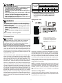
NOTE: Subsequent opening and replace of the cap will
require only 1/2 to 1 hex flat. See the table below for the
torque required for an effective seal on the valve bonnet (1/6
turn past finger tight.
TUBING SIZE
5/8
1 3/8
While reaching the proper subcooling level it is important to
know the discharge line temperature. This temperature should
be at least 80ºF over ambient or unit is flooding back to compressor. If flooding (i.e. low discharge line temperature) occurs, adjust valve stem on expansion valve inward (clockwise viewing end of expansion valve). This will increase the
super heat.
TORQUE
(ft-lbs)
14
16
After closing the valve bonnet, perform a final refrigerant leak
test on the valves and sweat connections. Return the room
thermostat to the desired settings.
Defrost Control Adjustments
This heat pump uses a Time/Temperature method for defrost. A thermal sensor electrically set to “Normally Open” is
wired to the electronic defrost control located in the control
box. The thermal sensor attached to the condenser coil determines the outdoor coil temperature.
7