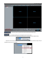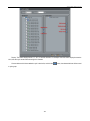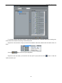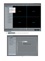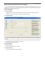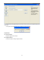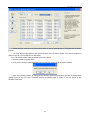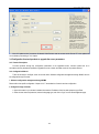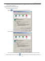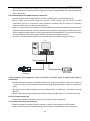
1
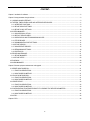
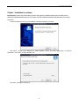
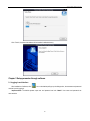
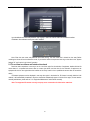
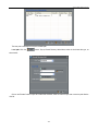
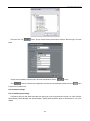
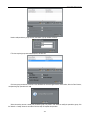
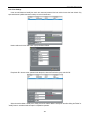
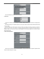
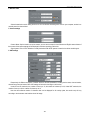
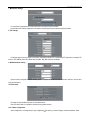
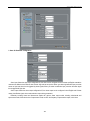
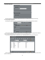
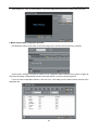
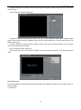
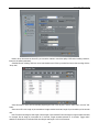
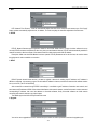
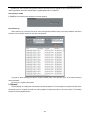
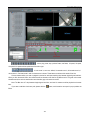
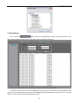
Network Video Manager System User Manual V1.7 Thank you for purchasing our products, please contact us at anytime if you have any question or requirement. It’s possible that there might be inaccurate places, inconsistencies between function and operation or print mistakes. We will update the manual according to the technical change, and shall not notify in advance with only renewing the manual contents. Network Video Manager System -CONTENTChapter 1 Installation for software ................................................................................................................................................ 2 Chapter 2 Setup parameter through software ............................................................................................................................... 3 2.1 LOGGING IN AND INTERFACE ......................................................................................................................................... 3 2.2 THE REAL TIME SURVEILLANCE AND INTERFACE INTRODUCED .............................................................................. 4 2.2.1 INTERFACE FUNCTIONS .......................................................................................................................................... 5 2.2.2 DEVICE GROUP SETTINGS ...................................................................................................................................... 8 2.2.3 DEVICE CYCLE SETTINGS ....................................................................................................................................... 8 2.3 SYSTEM MANAGER........................................................................................................................................................ 12 2.3.1 CONVENTIONAL OPTION ....................................................................................................................................... 13 2.3.2 DEFAULT DEVICE USERS ....................................................................................................................................... 13 2.3.3 VIDEO DISPLAY AND TRANSMISSION INCLUDE: ................................................................................................. 13 2.3.4 PTZ KEYBOARD ...................................................................................................................................................... 14 2.3.5 COMMUNICATION PORT SETTINGS...................................................................................................................... 14 2.3.6 DEVICE SEARCH ..................................................................................................................................................... 14 2.3.7 CONCENTRATE RECORD....................................................................................................................................... 15 2.3.8 PERMISSIONS SETTINGS ...................................................................................................................................... 18 2.3.9 SYSTEM LOG ........................................................................................................................................................... 21 2.4 DEVICE MAINTENANCE ................................................................................................................................................. 21 2.4.1 DEVICE MANAGER .................................................................................................................................................. 22 2.4.2 DEVICE SETUP ........................................................................................................................................................ 23 2.5 PLAYBACK ....................................................................................................................................................................... 38 2.6 ALARM MANAGER .......................................................................................................................................................... 40 Chapter 3 Remote equipment maintenance and upgrade .......................................................................................................... 41 3.1 SERVER CONFIGURATION ............................................................................................................................................ 41 3.1.1 FUNCTION DESCRIPTION ...................................................................................................................................... 41 3.1.2 CONFIGURATION METHOD .................................................................................................................................... 41 3.2 UPLOAD CONFIGURATION ............................................................................................................................................ 41 3.2.1 FUNCTION DESCRIPTION ...................................................................................................................................... 41 3.2.2 CONFIGURATION METHOD .................................................................................................................................... 41 3.3 UPDATE DEVICE ............................................................................................................................................................. 42 3.3.1 FUNCTION DESCRIPTION ...................................................................................................................................... 42 3.3.2 CONFIGURATION METHOD .................................................................................................................................... 42 3.4 CONFIGURATION FRONT-END PRODUCTS TO UPGRADE THE SERVER PARAMETERS ....................................... 44 3.4.1 FUNCTION DESCRIPTION ...................................................................................................................................... 44 3.4.2 CONFIGURATION METHOD .................................................................................................................................... 44 3.5 NOTES ............................................................................................................................................................................. 46 Chapter 4 FAQ ............................................................................................................................................................................ 46 -1- Network Video Manager System Chapter 1 Installation for software Important Note: Please notice that the video card driver must support the hardware speedup function. NVIDIA GeForce 6200/6600/7400/8600/9500/9600 series etc, ATI Radeon 7000/7200/7500/8500 /9000/9200 /9500/9600 series have already been tested. Double click Setup.exe, will pop up the installation confirmation dialogue box as below: Click “NEXT”, will pop up the dialogue box. Select installation location, the system default path is “C:\Program Files\NVMS”, click “Browse” to select installation path. Click “Next”, a dialogue box will pop up. -2- Network Video Manager System Click “Finish”, the client-side software will be installed in default directory. Chapter 2 Setup parameter through software 2.1 Logging in and interface After installation of software, click " " icon on the desktop will pop up the dialogue box, the username and password must be input for logging in. Important Note: The default system super user and password are both "admin". User name and password are case-sensitive. -3- Network Video Manager System Input the default user name and password, click ‘logging in’ button to enter the real time surveillance interface. IP Address: client software used by the local IP address. Note: Enter the user name and password three times wrong, The user name that is locked into the state, Before unlocking the former will not be allowed to re-use, If you need to unlock the super-user must log on the client in the "System Settings" "user" option in the "unlock" operation. 2.2 The real time surveillance and Interface introduced Real-time video connections in two ways: one is a list of the region for the selection of equipment, double-click the left mouse button in a specified sub-screen video to connect the device; and the other for the selection of equipment, the equipment list click on the region below the interface of the "Play" button in the a specified sub-screen video to connect the device. IP Camera equipment can be displayed in two ways the region in the device list, IP Camera is usually within the LAN network, it will automatically broadcast to the client, the device automatically appear in the list of the region; If users need to manually add devices, please refer to "2.3.1 Equipment Maintenance" add a device manually. Note: The supported IP cameras can only accept up to ten connections for video at the same time. -4- Network Video Manager System Video Cycle Setting Record ON/OFF Audio ON/OFF Record Icon Video turnoff PTZ three-dimensional positioning ON/OFF Device List Video Information Menu of right mouse Voice Setting PTZ control Stop Play Single full Screen Hide information Snapshot Image quality Image partition Note: Hover the mouse button 1 second, will automatically display the name of the button. 2.2.1 Interface functions Equipment sensor configuration: Click the right mouse button on the live video channel, the sensor configuration menu will be pop-up. The Brightness, saturation, sharpness, Image Mirror, Zone Exposure, AE/AGC, Day/Night and so on can be configured. (Note: The different IP device model has the different sensor configuration.) Note: When using some megapixels cameras the analog video output function of the camera will be effected during configuration and setup functions. It is normal effect on the smoothness of real-time video displayed. We recommend closing the analog video output function if it is not required to free up the resources of the IP camera CPU for better performance. Screen digital zoom function: Click and drag the left mouse button on the live video channel, a green box will be showed where the image is digital zooming automatically. You could to click the right mouse button on the live video channel to pop up menu and choose the "restore panorama" to see the natural live video. : Start/stop mutual-speak button, select the host IP in the list, click this button to start mutual-speak function, and click again to stop. : Voice setup button, available to setup Microphone volume, mute and microphone test.. -5- Network Video Manager System : Play button, select the host IP in the list, click Play Button to connect images of the selected the host. : Stop button, stop connection to the selected host. : Camera button, click this button to save the current image in single/series mode. Select camera setup will pop up the camera setup interface, see below: : Video quality button, after click, will pop up the image quality adjustment interface, see below. It’s available to adjust bit rate and quality value. It’s low value, better quality for quality value. Rate includes: CBR and VBR two options. CBR is a fixed rate, fixed rate can be manually input values; VBR variable bit rate to be within the 1-9 choice of quality, quality, value is higher the more clear, VBR, the bit rate value for the limit, that limit the maximum value of variable bit rate, such as the input rate of 1000, regardless of how much the value of quality, variable bit-rate maximum value not exceeding 1000. I Frame Interval: The interval between I frames is divided into three types 1/2/3 seconds, the screen for higher bit rate, frame interval should be shortened. The smaller the more favorable frame interval when the playback re-positioning accuracy, the more beneficial when the network jitter, the video resume, but the smaller the video stream frame interval the greater is recommended to use the default value 2S. -6- Network Video Manager System : Full screen button for Single video: when clicked, the selected video will be full screen. : Hide Information button: when clicked, the selected information column of video will be hidden. : Volume on-off and adjustment button. : PTZ 3D positioning: When you enable this function, you could use the left mouse button to click on video window and the PTZ will be automatic pointed to the video central. Drag the left mouse button to designate a rectangular area from top to bottom, the PTZ will be automatic pointed to the video central and zoomed in the video; the other hand, drag the left mouse button to designate a rectangular area from bottom to top, the PTZ will be automatic pointed to the video central and zoomed out the video. : Manual record button: The record parameter in manual record is as same as the concentrate record. If the parameters in concentrate record have not configured, the record parameters in manual record is used best resolution to record. Note: The prompt information will be showed if the parameters in concentrate record don't is configured and record service don't be started. About the simple retrieve video playback of the document please refer to "2.5 playback" section. : Audio on-off button, this button will be active while connecting to images, it is available to control audio on-off button. : Recording indicator, the indicator will become red while recording is going on. : Screen division setup button, from left to right: single, quarter, eight, nine, sixteen, thirty-six, full screen and hide information. Click ESC button to quit while it is full screen. Hide Information button: when clicked, the information column of all videos will be hidden. : Pan/tilt keyboard control buttons, available to execute the operation such as far and near, focus, direction and preset location etc to pan/tilt. Please refer to the "PTZ" parameters in the "2.4.2.3 device hardware configuration" section. If you want to control the preset, track, scan and speed function of PTZ, please click appeared as follows: -7- the button, the windows UI will be Network Video Manager System 2.2.2 Device group settings Right-click on the "device list" and select "Add Camera Group", the new device group will be added, as follow: Right-click on the new device group, the new camera group can be added, deleted and renamed operations. As follow: You could click left mouse button to select the device and drag it on camera group. 2.2.3 Device cycle settings Click the device cycle button into the cycle interface, as follow: -8- Network Video Manager System :It is the start, pause, stop, previous screen and next screen button from left to right :It is the add group, delete group and configuration button from left to right. Right-click on “Cycle list” and choose the “add cycle group” pop-up menu, a new cycle group will be added. As follow: Right-click on the new cycle group, the pop-up menu will be showed the add cycle group, delete cycle group and cycle configuration functions and so on. As follow: -9- Network Video Manager System Display: The screen display has the 1, 4, 8, 9, 16 and 36 channels. For example: when the screen display chooses the NO.4, the each cycle screen will be showing the 4 channels. Choose devices which have needed to cycle in device list, and click the to cycle group. -10- button, the selected devices will be moved Network Video Manager System For example as above, there are 5 screens in cycle group and interval time is 10 second. When cycle is starting, each screen which had 4 channels has showing 10 seconds every time. Right-click on the new screen, the pop-up menu will be showed the add screen, delete screen and rename screen. As follow: Click the button to save the cycle configurations. Right-click on the new screen, you could click the “start cycle” in pop-up menu and click quarter to start the cycle. -11- button on lower left Network Video Manager System 2.3 System Manager Click the button to enter system setup interface as below: -12- Network Video Manager System 2.3.1 Conventional option 1. Client-side voice selection: English, Chinese, Russian, German, French, Japanese, Spanish and Portuguese. 2. Open to auto-startup: select YES to setup auto-startup. 3. Recording service auto-startup: select YES to setup auto-startup. 2.3.2 Default Device Users Add the username and password of devices, so the soft client could connect to camera and get the parameters automatically. 2.3.3 Video display and transmission include: 1. Screen division number: 1, 4, 8,9,16 and 32. 2. Default transmission protocol: TCP, UDP and RTP. 3. Video stretching mode: The real-time video images will fill the entire play window. Whether or not to open video stretching mode, select YES to setup auto-startup. 4. Adaptive video resolution: The video resolution had adjusted by the size of the screen automatically. 5. According to the timestamp Play: scroll bar from left to right meaning low delay to high smooth video. The more Image smooth the more time delay. -13- Network Video Manager System 2.3.4 PTZ keyboard This function may through PTZ the keyboard connection computer remote control IP speed dome. Specific connection diagram is as follows: 2.3.5 Communication port settings Communication Port Settings to set alarm center listen port, register service listen port and broadcast service listen port. Alarm center to listen the default port 30004, Register services to listen the default port 30005, Broadcast service to listen the default port 30003. 2.3.6 Device Search Device search: According to configure the IP network segment and the port number, search for all IP devices in the network segment. Different ports can search the same network segment devices. -14- Network Video Manager System Active Search: First configure the IP range; the soft client will take the initiative to search for Network devices within the IP range. 2.3.7 Concentrate Record 2.3.7.1 Record Manager Click the "Record Manager" into the record management interface, as follow: Add the record device. Click the button, and the pop-up window will be showed as follow: -15- Network Video Manager System Choose record devices in the device list, add click the please click the button. If you want to configure the record parameters, button, the pop-up window will be showed as follow: Configure parameters of the record rule and stream. Disk group: The default is divided into 8 groups of disk group, the videos are recorded to a different disk group. 2.3.7.2 Store Configuration Click the “Store Config” menu into the store configuration interface as follow: -16- Network Video Manager System The store path is including the local path and NAS path. Local path: Click the button, Pop-up Record Directory Add window, select the local hard disk type, as shown below: Click on the "Browse" button to eject the browse folder interface, select the video that you want to save the path after the click OK. -17- Network Video Manager System NAS path: Click the button, Pop-up Record Directory Add window, select the NAS disk type, as shown below: Set the correct IP address of the NAS, path, username and password, click the Click button. button to save the store configuration and return the record manager interface, then click button to start the concentrate record. 2.3.8 Permissions settings 2.3.8.1 Permission group settings Permissions group can add, delete and modify user rights group. User group permissions include: Live Video, Playback, Alarm Manager, Device Manager and System Manager. System default permission group is "Administrators", can not be deleted. -18- Network Video Manager System Need to add permissions group click the "Add" button, pop-up window as follows: Fill in the required group name and description, and click OK: Click new group permissions, and then in the distribution of the basic rights need to check before, click the "Save" button; complete the group permissions to add. When the need to remove or modify the permission group, only need to click delete or modify the permission group, click the "delete" or "modify" button in accordance with the steps to complete the operation. -19- Network Video Manager System 2.3.8.2 User Settings Users can add, delete and modify the user's user name and password. And can unlock the user has been locked. Only super-administrator (default username is admin) can unlock locked users. Need to add user click the "Add" button, pop-up window as follows: Required to fill in the user name, password and description, select the Permissions group, and click OK: When the need to delete or modify users, simply click on the need to delete or modify the user after clicking the "Delete" or "modify" button in accordance with the steps to complete the operation. -20- Network Video Manager System 2.3.9 System log Select "System Log", in the query needed to enter query conditions, click on "Search" button; you can query the system log: System log types include five options: all types, real-time video, voice intercom, log on to the system and setting of equipment parameters。 The query system log is the client local database log records. 2.4 Device maintenance Click to enter the interface: -21- Network Video Manager System 2.4.1 Device manager Click device button to enter the interface as shown in figure: Input information such as IP address and name, etc, click “add” button, then “save” button, the added host will be shown in the host list of “real-time surveillance”, double click to connect the host. If you need the router port mapping, you could choose "Enable router mapping". In the router address will be added the -22- Network Video Manager System router's WAN address. The control mapping port and TCP A/V mapping port will be added the entrance port within the router can be set up. 2.4.2 Device setup Click the host in the from the Device Setup interface, to connect the host to configure its parameters。Include: device information, configure the device user name and password login, equipment hardware, alarm configuration, local recording, CMS configuration, network services and restart the equipment. 2.4.2.1 Login Settings IP Camera device registry settings to use the account and password. Account for the default "admin", the default password is "admin". Account number and password are case-sensitive. 2.4.2.2 Stream Setting Each device can be configured for different video stream, each device can be configured with up to three different video stream. 2.4.2.3 Equipment hardware configuration : Click the Refresh button to refresh the current page on the remote IP Camera equipment parameters. : Click Apply button to modify the current page has the parameters stored in the remote IP Camera equipment. Device hardware configuration, including network parameters, the name of the camera system, date and time, in/out -23- Network Video Manager System microphone option, PTZ parameters, RS485 parameters and disk format. 1. The local network parameters Can set the network IP camera address, subnet mask, gateway, DNS and other network parameters, If it is used in local area network You are cautioned not to set up the internal LAN IP address and computer IP address conflict .If you want to modify equipment IP protocol, the client must restart the selection of the corresponding IP protocol registry. If you want to use the IPv6 protocol equipment, first in the IP protocol IPv6 protocol options to choose and modify the network parameters, click on the "Apply" button. -24- Network Video Manager System Note: IPv6 addresses do not need to set the subnet mask. 2. Device Port Control port: The default is 30001, including the parameters of reading and writing, PTZ control and so on through this port to control; TCP audio and video port: The default is 30002, for the TCP protocol under the audio and video transmission which needs of the port number. Http Port: Default is 80, for Web access to use the port number. If you change it to another port number, you need in the address bar at the end add ": port number". For example, the equipment which IP is 192.168.10.96 and the Http port is changed to “8080”, you could enter the http://192.168.10.96:8080 in the IE browser's address bar to access the network device through the Web. 3. ADSL network parameters When the user set "Network Service"“PPPoE parameters”, after the success of dial-up equipment, Equipment’s WAN network IP address will appear in the page. -25- Network Video Manager System 4. Date and Time Select the method to use for setting the time: one is to set the time according to the clock on your computer; another is to manually enter the time and date. 5. Camera settings Camera Name: Options need to set up its camera, you can set the camera in both Chinese and English names. Name of the success of the camera settings will be displayed in real-time monitoring--Device list. Signal system: PAL or NTSC. Whether to modify the device's PAL/NTSC system is based on the device model support. 6. OSD settings Respectively for different resolutions of network device to set OSD parameters, including: device name, channel number, channel name, time and custom OSD. OSD settings will be held at the image on the overlay. Under CIF and D1 resolution, the number of rows up to 12, the number of columns up to 22; Under QCIF resolution, the number of rows up to 8, the number of columns up to 10. Note that the maximum number of characters that can be displayed for all overlays (date, time and/or text) will vary according to the characters used and the size of the image. -26- Network Video Manager System 7. Microphone settings In microphone: Equipment for IP Camera with built-in microphone near the camera. Out microphone:IP Camera equipment to the Audio In interface panel by the external microphone access. 8. PTZ settings IP Camera equipment can be used in front-end to configure the device PTZ corresponding PTZ parameters. Including PTZ Protocol, PTZ Address, Serial Port, Baud Rate, Data Bits, Stop Bits and Parity Verification. 9. RS485 Parameter setting Options need to configure the serial number; you can configure the serial port name, baud rate, data bits, stop bits and parity bit parameters. 10. Disk Format SD cards can be formatted to operate on the remote device. Note: SD card format is not allowed to read and write operations when. 2.4.2.4 Alarm configuration Alarm configuration, including alarm I/O port configuration, Disk warning, I/O alarm linkage, and motion detection alarm. -27- Network Video Manager System 1. Alarm I/O Parameter Configuration Alarm input: Select the alarm input configuration ID, the alarm can be configured in both Chinese and English entered the name and the effective level. Effective level include: high and low two options. When you select high effective input port when access to high level alarm that is triggered by alarm signals, When you select low effective input port when the alarm signal that is triggered off high alert. Alarm output: Select the alarm output configuration ID, the alarm output can be configured in both English and Chinese names, the effective signal, alarm mode and alarm output timing parameters. Effectively including closed and disconnects signals two options: Alarm output model, including switch-mode and square-wave mode, When the choice of square-wave mode, can fill in the frequency of square-wave output, unit is Hertz. -28- Network Video Manager System 2. Disk Alert Configuration Disk Alert configuration including: disk error alarm and disk full alarm. Disk alarm will be recorded in the alarm log. 3.I / O alarm linkage configuration Note: Before the opening of the record, we must first configure the "Local Record""Record Policy" parameter. Options need to configure the alarm I/O of the ID number, can be configured in the Alarm I/O trigger the alarm when the linkage. Including whether the alarm output and whether or not such as the opening of PTZ. First of all, check "Enable IO alarm ", and then click on the "Time Setting" set the I/O warning time of deployment: Check the need for deployment of the week, and set the beginning and ending days of deployment time, click the "Add" button, click "OK" button. -29- Network Video Manager System Select "Enable PTZ", Click "PTZ alarm settings" can be set to trigger alarms when the PTZ preset position and name. 4. Motion Detection Alarm Configuration interaction Note: Before the opening of the record, we must first configure the "Local Record""Record Policy" parameter. Options need to configure the camera ID number, can be configured to detect movement of the camera to trigger the alarm when the linkage. Including whether the alarm output and whether or not such as the opening of PTZ. First of all, select "Enable Motion Detection", then click on the "Time Setting" set the camera to detect movement of the deployment time, -30- Network Video Manager System Require the deployment of the week, and set the beginning and ending days of deployment time, click the "Add" button, click "OK" button. Click on "Detection of regional Configuration": Area Motion: Press and hold the left mouse button on the video in order to facilitate the sliding region configured to detect regions, when the need to remove the detection region can click the right mouse button. The most mobile region can not detect more than eight. Area mask: Hold down the left mouse button within the region to add a mask area, when the need to remove the mask area, you can click the right mouse button. Note: The maximum number of areas is 8. Select "Enable PTZ", click on the "Alarm PTZ settings" can be set to trigger alarms when the PTZ preset position and name. 2.4.2.5 Local record Local recording settings is the SD card and NAS video parameters.Once configured, the device can record video directly to an SD card and NAS. 1. Record Policy -31- Network Video Manager System Need to set up the camera to choose ID, you can set the camera to record the quality of SD cards, including: resolution, frame rate, bit-stream parameters. Schedule Record: Including 7X24-hour record and schedule record. When you select from time to time recording, click the "set-up time", Select the week to record, and set recording beginning and end of the day time, click the "Add" button, click the "OK" button。 Alarm record: fill in the Length of pre-recorded and Length recorded continued, Length of pre-recorded up to 30 seconds max. Note: Document recording the total length of time=Length of pre-recorded+ Event time length+ Length recorded continued, For example, Set the length of pre-recorded for 10 seconds, Length recorded continued for 10 seconds, Trigger motion detection for the duration of 5 seconds, While recording the total length =10+5+10=25 seconds。 -32- Network Video Manager System Days to keep video: Retain the largest number of days for 9999 days. Stream: Recording selected video stream ID. 2. Record Directory Set the device to the video directory, default including the SD card and NAS in two directories. SD Card: Click on the SD card entry, click on the button "modify", you can format the SD card, the following figure: NAS: Click on the NAS entry, click on the button "modify", the following figure: -33- Network Video Manager System Set the correct IP address of the NAS, path, username and password, Click enabled, you can record video directly to a device on the NAS. 2.4.2.6 CMS Configure CMS configuration includes alarm center, register center, FTP, and SMTP parameter settings. 1. Alarm Center -34- Network Video Manager System Alarm Center: When a warning alarm triggered when uploaded to a designated alarm center. Alarm Centre will pop up with an icon of a warning light in the in the lower right corner of the screen , click , the alerts information pop-up window will be showing current alarm information, the alarm log can also be searched through Alarm Manager. 2. Register Center Registration center: IP Camera device to set the address registration center to register. 3. FTP Record files will be stored at the FTP server when this FTP function is enabled. Note: when this FTP function is enabled, the record files will be not stored at the SD card. -35- Network Video Manager System 4. SMTP After SMTP is enabled, when triggered by motion detection, alarm and I / O alarm will be automatically sent JPG pictures and alarm information to the recipient's mailbox. 2.4.2.7 Network Services -36- Network Video Manager System 1. NTP NTP: Network Time Protocol。Host can automatically adjust the clock of the computer and connect sync. Click "Apply" button and then automatically adjust the time, In addition, 12 o'clock everyday, the automatic adjustment of service start。 2. PPPoE PPPoE: Network Camera support agreement based on the PPPoE WAN access. Through the client software is set up correctly PPPoE username and password, after every time you start Network Camera, PPPoE mode automatically establish a network connection, after the success of the network camera to obtain the dynamic WAN IP address. Description: Make sure that ADSL Modem has been opened. PPPoE parameters set for the first time, the need to restart the equipment in order to establish a connection. 3. DDNS DDNS: Dynamic domain Name service: It is better to register a domain for avoiding input IP address, as IP address is difficult to remember. It is necessary to get a PC with stable IP address in Internet, and domain name service software need to be run on the PC.(The PC will be DDNS) After connection to network through PPPoE successfully, it is available to get IP address of extensive area network, and send name and IP address to DDNS. When client-side software visits network camera, need to find network camera name and corresponding IP address, then send the address to client-side software; finally client-side software can build network connection with network camera to get video images. The DDNS support the 3322 and DynDns domain name 4. Upgrade You can be set to upgrade the server IP address and port number as well as parameters such as the upgrade cycle. -37- Network Video Manager System Upgrade cycle: unit is minutes; the upgrade process for each time interval to upgrade the server asked whether there is a need to upgrade the new version. Specific steps to upgrade please refer to "Chapter III." 2.4.2.8 Device to restart IP CAMERA to use remote control equipment, to resume operation. 2.4.2.8 Device log Select "Device Log" in the right "Device list", select the equipment needed to query in the query needed to enter query conditions, click on "Search" button, you can query the log device. Log types of device including five options: all types, real-time video, voice intercom, log on to the system setting of device parameters. Device Log is a log of the device itself. 2.5 Playback Record playback is including the local playback and remote playback. The local playback is played record files of the concentrate record on computer and NAS, the remote playback is played record files on SD card in device. The following example is the local playback function: -38- Network Video Manager System :It is the play, pause, stop, previous frame, next frame, 1/2 speed, 1/4 speed, 1/8 speed 1/16 speed and fast speed button from left to right. :It is the zoom in, zoom out, default, 10 seconds zoom in, 30 seconds zoom in, 1 minute zoom in, 5 minutes zoom in and 10 minutes zoom in button. These buttons could control the scale of time line. Choose cameras which you want to playback in device list and input searching time between beginning and end time. When you click the search button, the record files will be showed on the time line by different color. The green color means schedule record, the red color means alarm record and the gray color means no record. Note: The Max time is 7 days between beginning and end time, and max 16 cameras could be playback at the same time. If you want to add other local store path, please click the follow: -39- button, and choose the store path in pop-up window as Network Video Manager System 2.6 Alarm Manager Click on the top of button, Access to the Alarm Manager interface, choose “Alarm Search”, in the query, the input conditions required to query, click “Query” button, Can query the police log. Alarm types include four options: all types, I/O alarm, motion detection alarm and disk alarm. Inquiries by the alarm log, is the local client database for the log record, If you need the IP Camera equipment alarm, report to the client and record the log, Must be "Device Manager""CMS Configuration""Alarm Center" in the "Alarm Center IP" is set to install the client by the IP address of the PC. -40- Network Video Manager System Chapter 3 Remote equipment maintenance and upgrade First of all, please download the upgrade package to upgrade. The directory where the package was putted in can not contain spaces, so it must not be on the table. After the download is complete, open the "UpdateTool" directory, double-click "UpdateTool.exe", and begin the upgrade operation. 3.1 Server Configuration 3.1.1 Function Description (1)Upgrade the server to configure the startup parameters, including protocol version, listen address and listen port (2)Configure the root directory of products, the directory to manage all the packages 3.1.2 Configuration Method a. Click the tab "Configure". Dialog box appears as follows. b. Assign a local computer server IP Address as “Server IP” and an unused port as “Server port”. (Default port is suggested.) c. Click “browse”, and choose unoccupied directory as the root directory where the update package will be uploaded, and be noted no space allowed in the path of the product root directory. d. Click “Save” to save service parameters. 3.2 Upload Configuration 3.2.1 Function Description Upload the upgrade package to the root directory. 3.2.2 Configuration Method a. Click the tab "Upload". Dialog box appears as follows. -41- Network Video Manager System b. Choose the path of the upgrade package from the “Browse”. Please note that the path of upgrade package has not included space. c. Click “Upload” and the upgrade package will be uploaded to the product root directory. 3.3 Update Device 3.3.1 Function Description Configuration upgrade version and scope. 3.3.2 Configuration Method a. Click the tab "Update", the dialog box appears as follows: -42- Network Video Manager System b. Please select the model and version from each list which you want to update devices to. The default value of model is IPC8180. c. You could add and select Network video Device barcodes which you want to update. If you want to update all of devices in the LAN, you only select the “all” item directly. Note: The barcode number usually be marked on the shell of device. d. Click the “Update” to upgrade device. e. It will cost 2-3 minutes to update the devices, and you could click “refresh” to get information of update. f. Switch to the following interface, by clicking the Start Service to start the upgrade server. Start after the success of the upgrade service will pop up to start a successful interface, the following graph; by clicking on the "stop service" to stop escalation of the server. -43- Network Video Manager System Note: All “update service” parameters of Network Video Devices must be as same as the “Server IP” in the update tool. You could setup it according to “3.4” chapter. 3.4 Configuration front-end products to upgrade the server parameters 3.4.1 Function Description Front-end products through the configuration parameters of the upgraded servers, front-end product will be in accordance with the parameters specified to upgrade the server to obtain the latest version of the product software. 3.4.2 Configuration Method There are two ways to configure, users can choose either: Software configuration management through NVMS; also can be configured through a browser. 1. Software configuration management through NVMS Please refer to the specific configuration "chapter 2.4.2.7" the escalation of network services configuration. 2. Configure through a browser a. Open the browser in your browser's address bar enter the IP address of the front-end equipment, type Enter. b. Enter the user name and password, select the language type, and click on "login" to enter the management page. -44- Network Video Manager System c. Select bar “Network Service”, and then click “Update”. d. Fill in the IP address and port of the Upgrade the server on the right (must be configured the same as in step 1). -45- Network Video Manager System e. Configuration upgrades time, in minutes. Upgrade procedure for each interval that is long time to upgrade the server asked whether there is need to upgrade the new version. f. Click "OK" the application of the revised configuration. After the entire configuration, wait a few minutes, the front-end device will automatically upgrade. 3.5 Notes a. Upgrade tool (UpdateTool.exe), updateserver (updateserver.exe) and serverParameter.ini, Must be located in the same directory. b. Upgrade path and product packages in the root directory must not contain spaces, otherwise unsuccessful upload. c. All “update service” parameters of Network Video Devices must be as same as the “Server IP” in the update tool. d. Download the upgrade software package extension is ".rar". Chapter 4 FAQ 1. Connection with the client, attention should be paid what? Install "DirectX 9.0" more than the software version of the graphics acceleration; "DirectDraw" to speed up enabled; PC hardware requirements for the independence of more than 128M memory card. 2. Why can not local record? First of all, check SD-card whether the fault, or whether or not inserted into the SD-card slot; Check the "local recording - record store" and "plans to video" and other parameters are configured whether or not correctly; Note: Local recording is IP Camera device to record SD-card. 3. IP Camera Thermal issues IP Camera internal circuits have adopted the industry-level low-power chips, heat small. Heat sink is directly connected to the equipment chassis in order to increase heat dissipation IP Camera, improve IP Camera’s useful life. 4. Network connection of video signals do not show check reticle Whether exposure to good; or to IP camera line and the video monitor connected, to see whether the video signal, if have no, Note the camera problems; If there are images show a direct connection, please check your network connection is open, and then Check whether the computer system to install DirectX 9.0, DirectDraw is enabled to accelerate. 5. Can not control PTZ or the ball machine Detection of wiring is correct; Check the settings are correct. This setting should be in the "hardware equipmentPTZ”; Address set with PTZ or ball machine in line with the allocation of parking spaces; Confirm whether the agreement to match, for more information you can get in touch with product supplier. 6. How to log network with the client? If the client login, the first choice of log IP, This operation is in the PC card when the multi-client fixed network adapter to bind. Client default super user name and password are admin, case sensitive. During his visit IP Camera equipment need to enter a user name and password, by default are admin, case sensitive. LAN network, log in, the client will automatically search for the IP Camera is connected equipment IP. If you need access to the IP address not found, then the computer with the IP Camera network connection problems, check your computer's IP Camera and IP address settings are correct, cable connection is correct. Finally, through the "procedures""Run", type “ping <IP Camera ip> -t”, To see if "ping" of the pass. If the "ping" had, and then landing to the network. WAN network, the login client, first of all need to add equipment, Click on "Device Manager equipment -46- Network Video Manager System maintenance", IP Camera manually add devices such as IP address information, the save operation, can be a normal visit to IP camera equipment. 7. How to access the "IP camera" through IE? First need to set the IE ActiveX control: Right-click , Select "Properties", the system pop-up dialog box as follows: Select the "Security" "Custom Level", the system pop-up dialog box as follows: Option "Download unsigned ActiveX controls" set to enable, or set the Internet security to the minimum directly. Setting completed, Left click on the desktop icon, Open the IE browser, the IE browser's address input column you -47- Network Video Manager System want to visit the IP Camera Host IP address, click the enter key (ENTER), the login dialog box enter the correct user name and password to access the IP Camera equipment .IP Camera equipment default user name and password are admin, case-sensitive. 8. IP Camera equipment how to WAN connectivity and access? IP Camera equipment can be PPPoE dial-up to connect to the WAN network, to support the DDNS to visit. First IP Camera LAN connectivity through the equipment, "network services" within the PPPoE and DDNS (www.3322.org Sign up for a free domain name) configuration parameters. After the success of the application parameters, need to restart only after the dial-up equipment. Open the IE browser directly in the address bar enters the DDNS domain name server address to access IP Camera equipment. Enter the correct user name and password to enter the parameter setting interface of the IP Camera, in the "device configurationADSL network" can query WAN equipment IP Camera Network IP. If you need to visit the client IP Camera equipment, the client only needs to manually add the device with address normal visit. IP Camera、Computer and ADSL modem can be connected together with switches. Diagram is as follows: PC Fast Ethernet Switch PWR 10M100M ACT ACT 1 2 3 4 5 6 7 8 9 101112 COLCOL SWITCH 131415161718192021222324 1 2 3 4 5 6 7 8 9 10 11 12 13 14 15 16 17 18 19 20 21 22 23 24 UPLINK TALK / DATA TALK RS CS TR RD TD CD ADSL modem IP Camera 9. Why through the client program to connect to the device, the monitor screen in real-time image quality is unsatisfactory? IP Camera equipment connected to the default resolution is CIF, Variable bit rate (VBR), the quality of 5 (the quality of 1-7 from low to high), through the bottom of the client video quality adjustment function to change the resolution and quality. Resolution from low to high, including the four: Super Low Bitrate QCIF、Low Bitrate CIF、Low Bitrate D1 and High Bitrate D1. Bit rate including the two: VBR (Variable bit rate) and CBR (Fixed bit rate).VBR quality is 1-7 of them from low to high. 10. SD card support hot-plug it? Support, but the devices are advised to avoid the use of hot-plug SD cards, avoid data loss. 11. SD card can not be used, how should I do? Please check whether the partition SD card, if there was no partition on the first partition in the PC operation. Used for the first time will be automatically formatted SD card, make sure that the SD has been the backup data. -48- Network Video Manager System 12. Which external devices can work together with IP Camera? IP Camera can be used in conjunction with the keyboard; can access a wide range of control decoders, alarm input and output devices, alarm host, access control systems. -49-