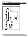
1
Dual Compressor/Gate
User Manual
Professional Audio Equipment
IMPORTANT SAFETY INFORMATION
WARNING FOR YOUR PROTECTION
READ THE FOLLOWING:
KEEP THESE INSTRUCTIONS
HEED ALL WARNINGS
FOLLOW ALL INSTRUCTIONS
The symbols shown above are internationally accepted symbols that warn of
potential hazards with electrical products. The lightning flash with arrowpoint in
an equilateral triangle means that there are dangerous voltages present within
the unit. The exclamation point in an equilateral triangle indicates that it is
necessary for the user to refer to the owner’s manual.
These symbols warn that there are no user serviceable parts inside the unit.
Do not open the unit. Do not attempt to service the unit yourself. Refer all
servicing to qualified personnel. Opening the chassis for any reason will void
the manufacturer’s warranty. Do not get the unit wet. If liquid is spilled on the
unit, shut it off immediately and take it to a dealer for service. Disconnect the
unit during storms to prevent damage.
Safety Instructions
Notice For Customers If Your Unit Is Equipped With A Power Cord.
WARNING: THIS APPLIANCE SHALL BE CONNECTED TO A MAINS SOCKET OUTLET WITH A
PROTECTIVE EARTHING CONNECTION.
The cores in the mains lead are coloured in accordance with the following code:
GREEN and YELLOW - Earth
BLUE - Neutral
the apparatus shall not be exposed to dripping or splashing
liquid and no object filled withi liquid, such as vases, shall
be placed on the apparatus.
CLEAN ONLY WITH A DRY CLOTH.
DO NOT BLOCK ANY OF THE VENTILATION OPENINGS. INSTALL IN ACCORDANCE WITH THE MANUFACTURER’S INSTRUCTIONS.
DO NOT INSTALL NEAR ANY HEAT SOURCES SUCH AS RADIATORS,
HEAT REGISTERS, STOVES, OR OTHER APPARATUS (INCLUDING AMPLIFIERS) THAT PRODUCE HEAT.
ONLY USE ATTACHMENTS/ACCESSORIES SPECIFIED BY THE MANUFACTURER.
UNPLUG THIS APPARATUS DURING LIGHTNING STORMS OR WHEN
UNUSED FOR LONG PERIODS OF TIME.
Do not defeat the safety purpose of the polarized or grounding-type plug. A
polarized plug has two blades with one wider than the other. A grounding
type plug has two blades and a third grounding prong. The wide blade or third
prong are provided for your safety. If the provided plug does not fit your outlet, consult an electrician for replacement of the obsolete outlet.
Protect the power cord from being walked on or pinched particularly at plugs,
convenience receptacles, and the point where they exit from the apparatus.
Use only with the cart stand, tripod bracket, or table specified by the manufacture, or sold with the apparatus. When a cart is used, use caution when moving
the cart/apparatus combination to avoid injury from tip-over.
BROWN - Live
As colours of the cores in the mains lead of this appliance may not correspond with the coloured
markings identifying the terminals in your plug, proceed as follows:
• The core which is coloured green and yellow must be connected to the terminal in the plug
marked with the letter E, or with the earth symbol, or coloured green, or green and yellow.
• The core which is coloured blue must be connected to the terminal marked N or coloured
black.
• The core which is coloured brown must be connected to the terminal marked L or coloured
red.
This equipment may require the use of a different line cord, attachment plug, or both, depending
on the available power source at installation. If the attachment plug needs to be changed, refer
servicing to qualified service personnel who should refer to the table below. The green/yellow
wire shall be connected directly to the units chassis.
CONDUCTOR
L
N
LIVE
NEUTRAL
E
EARTH GND
WIRE COLOR
Normal
Alt
BROWN
BLACK
BLUE
WHITE
GREEN/
GREEN
YEL
WARNING: If the ground is defeated, certain fault conditions in the unit or in the system to
which it is connected can result in full line voltage between chassis and earth ground. Severe
injury or death can then result if the chassis and earth ground are touched simultaneously.
Refer all servicing to qualified service personnel. Servicing is required when
the apparatus has been damaged in any way, such as power-supply cord or plug
is damaged, liquid has been spilled or objects have fallen into the apparatus, the
apparatus has been exposed to rain or moisture, does not operate normally, or
has been dropped.
POWER ON/OFF SWITCH: If the equipment has a Power switch, the Power
switch used in this piece of equipment DOES NOT break the connection from
the mains.
MAINS DISCONNECT: The plug shall remain readily operable. For rackmount or installation where plug is not accessible, an all-pole mains switch with
a contact separation of at least 3 mm in each pole shall be incorporated into
the electrical installation of the rack or building.
FOR UNITS EQUIPPED WITH EXTERNALLY ACCESSIBLE FUSE RECEPTACLE: Replace fuse with same type and rating only.
MULTIPLE-INPUT VOLTAGE: This equipment may require the use of a different
line cord, attachment plug, or both, depending on the available power source at
installation. Connect this equipment only to the power source indicated on the
equipment rear panel. To reduce the risk of fire or electric shock, refer servicing to qualified service personnel or equivalent.
If connected to 240V supply, a suitable CSA/UL certified power cord shall be
used for this supply.
IMPORTANT SAFETY INFORMATION
ELECTROMAGNETIC
COMPATIBILITY
This unit conforms to the Product Specifications noted on the
Declaration of Conformity. Operation is subject to the following two
conditions:
• this device may not cause harmful interference, and
• this device must accept any interference received, including
interference that may cause undesired operation.
Operation of this unit within significant
electromagnetic fields should be avoided.
• use only shielded interconnecting cables.
U.K. MAINS PLUG WARNING
A molded mains plug that has been cut off from the cord is unsafe.
Discard the mains plug at a suitable disposal facility.
NEVER UNDER ANY CIRCUMSTANCES SHOULD YOU
INSERT A DAMAGED OR CUT MAINS PLUG INTO A 13
AMP POWER SOCKET.
Do not use the mains plug without the fuse cover in place.
Replacement fuse covers can be obtained from your local retailer.
Replacement fuses are 13 amps and MUST be ASTA approved to
BS1362.
If you want to dispose this product, do not mix it with general household waste. There is a
separate collection system for used electronic products in accordance with legislation that
requires proper treatment, recovery and recycling.
Private household in the 25 member states of the EU, in Switzerland and Norway may return their used
electronic products free of charge to designated collection facilities or to a retailer (if you purchase a similar
new one).
For Countries not mentioned above, please contact your local authorities for a correct method of disposal.
By doing so you will ensure that your disposed product undergoes the necessary treatment, recovery and
recycling and thus prevent potential negative effects on the environment and human health.
DECLARATION OF
CONFORMITY
Manufacturer’s Name:
dbx Professional Products
Manufacturer’s Address:
8760 S. Sandy Parkway
Sandy, Utah 84070, USA
declares that the product:
Product name:
dbx 266xs
Note: Product name may be suffixed by the EU.
Product option:None
conforms to the following Product Specifications:
Safety:IEC 60065 -01+Amd 1
EMC:EN 55022:2006 (N/A; Analog Product)
IEC61000-4-2
IEC61000-4-3
IEC61000-4-4
IEC61000-4-5
IEC61000-4-6
IEC61000-4-8
IEC61000-4-11
Supplementary Information:
The product herewith complies with the requirements of the:
Low Voltage Directive 2006/95/EC
EMC Directive 2004/108/EC.
RoHS Directive 2002/95/EC
WEEE Directive 2002/96/EC
With regard to Directive 2005/32/EC and EC Regulation
1275/2008 of 17 December 2008, this product is designed,
produced, and classified as Professional Audio Equipment and
thus is exempt from this Directive.
Roger Johnsen
Vice President of Engineering
8760 S. Sandy Parkway
Sandy, Utah 84070, USA
Date: November 1, 2010
European Contact: Your local dbx Sales and Service Office or
Harman Music Group
8760 South Sandy Parkway
Sandy, Utah 84070, USA
Ph: (801) 566-8800
Fax: (801) 568-7583
Table of Contents
Section 1- Introduction........................... 1
1.1 Commom Compressor Applications..... 1
1.2 Common Gating Applications............ 1
1.3 Service Contact Info........................ 2
1.4 Warranty........................................ 3
Section 2- Getting Started....................... 4
2.1 Rear Panel Connections................... 4
2.2 Front Panel Connections.................. 5
Section 3 - Making Connections ............... 8
Section 4 - Technical Support and Facts..... 9
4.1 Technical Support........................... 9
4.2 Registration Card and User Feedback.... 9
Section A - Appendix................................ 10
A.1 Technical Specifications................... 10
A.2 Block Diagram................................ 11
dbx 266xs
dbx 266xs
Introduction
Section 1
Section 1 - Introduction
Congratulations on choosing the dbx 266xs Compressor/Gate. The 266xs provides traditional
dbx sonic quality and performance for the working musician, DJ, studio operator or anyone who
needs a friendly compressor/gate to achieve quality compression, gating and downward
expansion quickly and easily. We recommend that you take a moment and read through the
manual as it provides information that will assist you in using your unit to its fullest potential.
1.1 Common Compressor Applications
•
•
•
•
•
•
Fattening a Kick Drum or Snare Drum
Adding Sustain to Guitar or Synthesizer String Sounds
Smoothing Out a Vocal Performance
Raising a Signal Out of a Mix
Preventing Sound System Overload
Digital to Analog Transfers
The 266xs compressor is packed with just the right features to effectively reduce and control
the dynamic range of your audio, add punch to flabby, loose sounds, or add sustain to
instruments. The 266xs begins with the classic dbx compression made famous by our 160 line
of compressors. Just set the 266xs Attack and Release controls to 12:00 to get the same
response as those units. But there’s more. We scaled the program-dependent Attack and
Release controls with dbx’s AutoDynamic™ circuitry, so that the 266xs full range of controls
produce voicings that extend from slow leveling to aggressive peak limiting.
1.2 Common Gating Applications
•
•
•
•
Gating Dry Percussive Sounds (e.g., Snare Drum, Kick Drum)
Gating Sounds That Have Longer Decay (e.g., Cymbal, Piano)
Gating Hum or Buzz From Live Instruments or Recorded Tracks
Downward Expansion to Reduce Noise Under Smooth Sounds (e.g., Vocals, Woodwinds)
The 266xs gate is ready to tackle all your gating needs, whether you need to remove
unwanted noise or other background sounds, tighten drum sounds, or change the
characteristic envelope of an instrument. The 266xs gate provides more flexibility than
traditional switch gates because it actually functions as a combination gate/expander. Where
switch gates are generally only suitable for a limited number of uses (e.g., gating percussion),
the gate on the 266xs acts as a gentle downward expander at low Ratio settings (suitable for
vocals, guitar, mixed program, etc.), and can effectively work as a switch gate when used at
high Ratio settings.
Refer to the following pages for suggested initial settings. These settings should suffice for
traditional compressing and gating requirements. However, the 266xs can accomplish many
more changes to sound quality. We recommend that you experiment with the 266xs controls;
take our suggested settings and run with them, try totally different settings, and try
unorthodox combinations of compressor and gating controls. You might be surprised at what
you hear. Best of all, you may create the perfect sound quality for your needs.
1
Section 1
Introduction
dbx 266xs
1.3 Service Contact Info
If you require technical support, contact dbx Technical Support. Be prepared to accurately
describe the problem. Know the serial number of your device - this is printed on a sticker
attached to the chassis. If you have not already taken the time to fill out your warranty
registration card and send it in, please do so now. You may also register online at
www.dbxpro.com.
Before you return a product to the factory for service, we recommend you refer to the manual.
Make sure you have correctly followed installation steps and operation procedures. For further
technical assistance or service, please contact our Technical Support Department at (801)
568-7660 or visit www.dbxpro.com. If you need to return a product to the factory for service,
you MUST first contact Technical Support to obtain a Return Authorization Number.
No returned products will be accepted at the factory without a Return Authorization Number.
Please refer to the Warranty information on the following page, which extends to the first
end-user. After expiration of the warranty, a reasonable charge will be made for parts, labor,
and packing if you choose to use the factory service facility. In all cases, you are responsible
for transportation charges to the factory. dbx will pay return shipping if the unit is still under
warranty.
Use the original packing material if it is available. Mark the package with the name of the
shipper and with these words in red: DELICATE INSTRUMENT, FRAGILE! Also write the Return
Authorization Number (RA#) on the outside of the box in a conspicuous location. Insure the
package properly. Ship prepaid, not collect. Do not ship parcel post.
2
dbx 266xs
Introduction
Section 1
1.4 Warranty
This warranty is valid only for the original purchaser and only in the United States.
1. The warranty registration card that accompanies this product must be mailed within 30
days after purchase date to validate this warranty. You can also register online at
www.dbxpro.com. Proof-of-purchase is considered to be the responsibility of the consumer. A
copy of the original purchase receipt must be provided for any warranty service.
2. dbx warrants this product, when bought and used solely within the U.S., to be free from
defects in materials and workmanship under normal use and service.
3. dbx liability under this warranty is limited to repairing or, at our discretion, replacing
defective materials that show evidence of defect, provided the product is returned to dbx
WITH RETURN AUTHORIZATION from the factory, where all parts and labor will be covered up
to a period of two years. A Return Authorization number must first be obtained from dbx. The
company shall not be liable for any consequential damage as a result of the product’s use in
any circuit or assembly.
4. dbx reserves the right to make changes in design or make additions to or improvements
upon this product without incurring any obligation to install the same additions or
improvements on products previously manufactured.
5. The foregoing is in lieu of all other warranties, expressed or implied, and dbx neither
assumes nor authorizes any person to assume on its behalf any obligation or liability in
connection with the sale of this product. In no event shall dbx or its dealers be liable for
special or consequential damages or from any delay in the performance of this warranty due to
causes beyond their control.
3
Section 2
Getting Started
dbx 266xs
Section 2 - Getting Started
2.1 Rear Panel Connections
IEC Power Cord Receptacle
The dbx 266xs comes with a power supply that will accept voltages ranging from 100V-120V
at frequencies from 50Hz-60Hz. An IEC cord is included. EU version accepts 220V-240V at
frequencies from 50Hz-60Hz.
WARNING: Be sure to verify your actual line voltage is the same
as the voltage level printed below the AC power receptacle.
Connection to an inappropriate power source may result in
extensive damage which is not covered by the warranty.
Caution: Never remove the cover. There are no user-serviceable parts inside.
INPUT Jacks (CHANNEL 1 and 2)
Use 1/4” TRS phone plugs or male XLR plugs to connect these inputs to your source. The
266xs INPUT jacks accept either balanced or unbalanced signals. Input impedance is >40kΩ.
OUTPUT Jacks (CHANNEL 1 and 2)
The OUTPUT jacks accept 1/4” TRS balanced or unbalanced phone plugs or female XLR plugs.
Maximum output signal level is >+20dBu. In the +4dBu setting, the balanced output
impedance is 100Ω, and the unbalanced output impedance is 50Ω. In the -10dBV setting, the
balanced output impedance is 1kΩ and the unbalanced output impedance is 500Ω.
OPERATING LEVEL Switch
This switch selects between a -10dBV and +4dBu nominal operating level. When the switch is
in the in position, a -10dBV operating level is selected. When it is in the out position, a
+4dBu operating level is selected.
SIDECHAIN INSERT Jack
This jack accepts 1/4” TRS phone plugs and provides a connection to the 266xs detector path.
The RING acts as a Send, carrying a buffered version of the signal present at the 266xs INPUT
jack, at an impedance of 2kΩ. The TIP acts as a Return for equipment to feed the 266xs
detector circuitry, such as an equalizer for de-essing or frequency-sensitive gating/compression. You can also drive the 266xs Sidechain input with the output of most equipment, by
using a 1/4” mono phone plug. Input Impedance is greater than 10kΩ.
NOTE: When a cable is plugged into this jack, it automatically breaks the connection from
the INPUT jack to the 266xs detection circuitry.
4
dbx 266xs
Getting Started
Section 2
2.2 Front Panel Connections
STEREO COUPLE Switch
This switch sets the 266xs for Stereo or Dual Mono operation. Press the STEREO COUPLE switch
in for stereo operation where Channel 1 becomes the master controller for both channels. All
of Channel 2’s controls, switches, and LEDs will be disabled (except for the Channel 2 GAIN
REDUCTION meter), since Channel 2 is the slave.
With the STEREO COUPLE switch out, the unit functions as two separate mono compressor/
gates, each with its own independent controls.
The STEREO COUPLE switch lights red when the 266xs is stereo-coupled.
BYPASS Switch
Press this switch in to bypass the front panel controls, effectively canceling the function and
processing effect of the 266xs compression, gating and gain settings. The input signal is still
present at the 266xs Output, but is now unaltered by the 266xs controls. BYPASS is especially
useful for making comparisons between processed and unprocessed signals. Note that with
stereo operation (STEREO COUPLE switch pressed in), the Channel 1 BYPASS switch controls
both channels.
The BYPASS switch lights red when BYPASS mode is active.
GAIN REDUCTION (dB) Meter
This meter displays the amount of signal attenuated from the input signal by the 266xs
Compressor or Expander/Gate. When the Compressor and Expander/Gate are both active, the
meter displays the maximum amount of gain reduction for whichever function is greater Compressor or Expander/Gate.
OUTPUT GAIN (dB) Control
This control sets the overall gain of the 266xs, from -20dB to +20dB. The OUTPUT GAIN
control is especially useful to compensate for the RMS level decrease which results from the
266xs dynamic processing effects. After you adjust the 266xs controls for the desired amount
of compression, set the OUTPUT GAIN to add the same amount of gain that is shown on the
GAIN REDUCTION meters. For example, if the average amount of gain reduction shown on the
meters is 10dB, then setting the OUTPUT GAIN control to +10dB will compensate for the 10dB
average level reduction at the output.
NOTE: The 266xs Compressor and Expander/Gate control settings are interactive and can
affect gain, so watch your playback levels.
NOTE: Setting the Compressor RATIO to 1:1 will turn the Compressor off, regardless of the
setting of the Compressor THRESHOLD control and BELOW/OVEREASY/ABOVE LED status.
Setting the Compressor THRESHOLD control to +20dB will prevent all but the highest level
peaks from being compressed.
5
Section 2
Getting Started
dbx 266xs
OVEREASY® Switch
Depress this switch to select the OverEasy® compression characteristic. The amber THRESHOLD
LED turns on when the signal is in the OverEasy region. When the switch is out, the 266xs
operates as a hard-knee compressor, and the amber LED does not light.
Compressor THRESHOLD Control and LEDs (BELOW/OVEREASY/ABOVE)
Adjust this control to set the threshold of compression from - 40dB to +20dB. In hard-knee
mode, the threshold of compression is defined as the point above which the output level no
longer changes on a 1:1 basis with changes in the input level.
In OverEasy mode the threshold of compression is defined as the middle of the OverEasy
threshold region, that is, “half-way” into compression.
The three THRESHOLD LEDs indicate the relationship of the input signal level to the threshold
of compression. The green LED lights when the signal is BELOW threshold, the red LED lights
when the signal is above threshold, and the yellow LED lights when the OVEREASY switch is
depressed and the input signal is in the OVEREASY range.
The 266xs OverEasy compression permits extremely smooth, natural sounding compression,
without artifacts, due to the gradual change of compression around the threshold. With
OverEasy compression, input signals begin to gradually activate the 266xs internal gain
change circuitry as they approach the THRESHOLD reference level. They do not get fully processed by the RATIO, ATTACK and RELEASE controls until they have passed somewhat above
the THRESHOLD reference level. As the signal level passes the THRESHOLD level, processing
increases until it is fully processed to the extent determined by the control settings.
In hard-knee mode, the 266xs can provide abrupt compression effects as well as hard-limiting
applications. Note that when in hard knee mode the amber LED will not light as the input
signal passes across the threshold. The signal is either being compressed (over threshold) or it
is not being compressed (under threshold).
NOTE: Even though no input signal is being applied, it is normal for the LEDs to flicker on
when the power is applied or removed.
Compressor RATIO Control
Adjust this control to set the amount of compression applied to the input signal. Clockwise
rotation of this control increases the compression ratio from 1:1 (no compression) up to ∞:1
(where the compressor can be considered to be a peak limiter, especially with faster ATTACK
settings).
When an input is above the THRESHOLD setting reference level, the RATIO setting determines
the number of decibels by which the input signal must increase in level to produce a 1dB
increase in the signal level at the output of the 266xs. A setting of 2:1 indicates an input/
output ratio wherein a 2dB increase in signal (above threshold) will produce a 1dB increase in
output signal. A setting of ∞:1 indicates that an infinite increase in input level would be
required to raise the output level by 1dB.
6
dbx 266xs
Getting Started
Section 2
Compressor ATTACK and RELEASE Control
The ATTACK control sets the amount of time it takes the 266xs to begin compressing a signal
once the detector has sensed a signal above threshold. The ATTACK range is from FAST (for a
tighter and more noticeable compression effect with very little overshoot) to SLOW (for more
delayed, gradual compression). A very fast ATTACK setting will cause the 266xs to act like a
peak limiter even though RMS detection circuitry is used. Slower ATTACK settings cause the
266xs to act like an RMS or averaging detecting compressor/limiter.
The RELEASE control sets how fast the compression circuit returns the input to its original
level. The RELEASE rate is from FAST (where compression follows the envelope of the program
material very tightly) to SLOW (for very smooth compression).
There is no absolute right way to set the ATTACK and RELEASE controls. However, in general,
you will want them set slow enough to avoid pumping or breathing sounds caused when
background sounds are audibly modulated by the dominant signal energy, yet the release must
be fast enough to avoid suppression of the desired signal after a sudden transient or loud
note has decayed. For low frequency tones (e.g., bass guitar), set RELEASE and ATTACK to
2:00 or slower.
NOTE: ATTACK and RELEASE controls operate together and in conjunction with the RATIO
control. Changing one control may necessitate changing another setting.
AUTO Switch
This switch overrides both the ATTACK and RELEASE controls and enables preset programdependent attack and release times. These times are derived from the input signal and continuously change to match its dynamics. Enabling this AUTO Function duplicates the “classic
dbx sound” of the 266xs forerunners which have become standards in the industry.
Expander/Gate THRESHOLD Control and LEDs (BELOW/ABOVE)
NOTE: The Expander/Gate is off when the Expander/Gate THRESHOLD is set to OFF.
Adjusting this control sets the level at which the gate will open and allow the signal at the
input to pass through to the output. Turning the knob fully counterclockwise (to OFF) allows
the gate to pass all signals unattenuated, effectively bypassing the gate. Turning the knob
fully clockwise causes the gate to attenuate input signals below +15dBu. The depth of attenuation depends on the setting of the Expander/Gate RATIO control.
The two Expander/Gate LEDs indicate the relationship of the input signal level to the threshold setting. The red LED lights when the signal is BELOW threshold, the green LED lights when
the signal is above threshold.
7
Section 3
Making Connections
dbx 266xs
Expander/Gate RATIO Control
This control sets the amount of attenuation applied to the input signal once it is below the
threshold, from gentle downward expansion (appropriate for mixed program, vocals, etc.), to a
hard gating effect (which can be useful for percussion). Fairly low RATIO (and higher
Expander/Gate THRESHOLD) settings work best for downward expansion, whereas higher RATIO
settings (clockwise towards MAX) work best for gating. If a setting produces undesirable
pumping, readjust the Expander/Gate RATIO or THRESHOLD setting.
NOTE: The attack and release rate of the Expander/Gate are program-dependent - very fast
for transient material (e.g., percussion) and slower for material with slow attack (e.g.,
vocals).
NOTE: Fast gating of sustained low frequency signals can result in “chattering”. To
eliminate any “chattering” simply adjust the RATIO control. The proper THRESHOLD setting
will also minimize false triggering and “chattering.”
Section 3 - Making Connections
The 266xs can be used with any line-level device. Some common examples include
mixing consoles, electronic musical instruments, patch bays, and signal processors.
For all connections, refer to the following steps:
Turn Off all equipment before making any connections.
Mount the 266xs in a 1U rack space (optional).
The 266xs requires one rack space (height) and 1 rack space (width). It can be
mounted above or below anything that doesn’t generate excessive heat, since it
requires no special ventilation. Ambient temperatures should not exceed 113ºF (45ºC)
when equipment is powered.
Make connections via 1/4” TRS phone or XLR jacks according to your requirements.
Typical patch points include: a mixer’s channel or subgroup inserts when using the
266xs on individual instruments or tracks; the mixer’s main outputs when mixing; an
instrument preamp’s effects loop when using the 266xs for guitar or bass; main outs
of a submixer (i.e., keyboard mixer) as the signal is sent to main mixer; between a
DAT’s output and an analog cassette input. When using a chain of processors, the
266xs may be placed either before or after effects or dynamics processors. We recommend
you use common sense and experiment with different setups to see which
one provides the best results for your needs.
Connect the AC power cord (shipped with the unit) to the 266xs rear panel
POWER connector and an appropriate AC power source to turn the unit ON.
8
dbx 266xs
Technical Support and Facts
Section 4
Section 4 - Technical Support and Facts
4.1 Technical Support
The 266xs is an all-solid-state product with components chosen for high performance
and excellent reliability. Each 266xs is tested, burned-in and calibrated at the factory
and should require no internal adjustment of any type throughout the life of the unit.
We recommend that your 266xs be returned to the factory only after referring to the
manual and consulting with dbx Customer Service.
Our phone number, Fax number and address are listed on the back cover of this manual.
When you contact dbx Customer Service, be prepared to accurately describe the problem.
Know the serial number of your unit. This is printed on a sticker attached to the
side panel of the unit.
NOTE: Please refer to the terms of your Limited Two-Year Standard Warranty, which extends
to the first end user. After the warranty expires, a reasonable charge will be made for
parts, labor, and packing if you choose to use the factory service facility. In all cases, you
are responsible for shipping charges to the factory. dbx will pay return shipping if the unit
is still under warranty.
Shipping Instructions: Use the original packing material if it is available. Mark the
package with the name of the shipper, and with these words in red: DELICATE INSTRUMENT,
FRAGILE! Insure the package properly. Ship prepaid, not collect. Do not ship parcel post.
4.2 Registration Card and User Feedback
We appreciate your feedback. After you have an opportunity to use your new 266xs,
please complete the Registration Card and return it.
9
Section A
dbx 266xs
Appendix
Section A - Appendix
A.1 Technical Specifications
Note: 0dBu = 0.775VRMS
Specifications are subject to change
INPUT (Balanced or Unbalanced):
Impedance:
> 40kΩ
Max Level: +22dBu
OUTPUT (Impedance Balanced):
Impedance:
Max Level:
+4dBu: Balanced: 100Ω
Unbalanced: 50Ω
-10dBu: Balanced: 1kΩ
Unbalanced: 500Ω
> +21dBu, > +18dBm (into 600Ω)
SIDECHAIN INSERT:
Input Impedance: Output Impedance: Max Input Level:
Max Output Level: >10kΩ
2kΩ
+22dBu
>+20dBu
FREQUENCY RESPONSE:
Flat:
Bandwidth:
20Hz - 20kHz, +0, -0.5dB
0.35Hz - 90kHz, +0, -3dB
SYSTEM PERFORMANCE:
Distortion + Noise:
Intermodulation Distortion:
Noise:
Dynamic Range:
Interchannel Crosstalk:
Common Mode Rejection:
Stereo Coupling:
<0.2%; any amount of compression at 1kHz
<0.2% SMPTE
<-93dB, unweighted (22kHz measurement bandwidth)
>114dB, unweighted
<-95dB, 20Hz to 20kHz
>40dB, typically >55dB @ 1kHz
True RMS Power Summing™
THRESHOLD:
Compressor:
Expander/Gate:
RATIO:
Compressor:
Expander/Gate:
ATTACK Time:
Compressor:
Expander/Gate:
RELEASE Time:
Compressor:
Expander/Gate:
10
OverEasy® or hard-knee; -40dBu to +20dBu
-60dBu to +10dBu
1:1 to Infinity:1
1:1 to 4:1
Scalable Program-Dependent AutoDynamic™
<100μSec
Scalable Program-Dependent AutoDynamic™
Program-Dependent
Power Supply:
Operating Voltage: Power Consumption: Operating Temperature: 100VAC -120VAC 50/60Hz; 230VAC 50/60Hz
15 Watts
32°F to 113°F (0°C to 45°C)
PHYSICAL:
Net Weight: Shipping Weight: Dimensions:
4.84 lbs (2.19kg)
6.6 lbs (2.99kg)
1.75” (4.4cm) H x 5.75” (14.6cm) D x 19” (48.26cm) W
dbx 266xs
Appendix
Section A
A.2 Block Diagram
11
8760 South Sandy Parkway • Sandy, Utah 84070
Phone: (801) 568-7660 • Fax (801) 568-7662
Int’l Fax: (801) 568-7583
Questions or comments?
Contact us at www.dbxpro.com
Printed in China
18-0806-A