1
Specifications
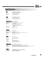
Input
Connectors:
Type: Impedance:
Max Input Level:
CMRR:
Output
Connectors:
Type:
Impedance:
Max Output Level:
Female XLR and 1/4” TRS (Pin 2 and tip hot)
Electronically balanced/unbalanced, RF filtered
Balanced > 50 kΩ, unbalanced >25 kΩ
> +24 dBu balanced or unbalanced
40 dB; Typically >55 dB at 1 kHz
Male XLR and 1/4” TRS (Pin 2 and tip hot)
Servo-balanced/unbalanced, RF filtered
Balanced 60Ω, unbalanced 30Ω
> +21 dBu, >+20 dBm balanced/unbalanced
System Performance
Bandwidth:
20 Hz to 20 kHz, +0/-0.5 dB
Frequency Response:
0.35 Hz to 200 kHz, +0/-3 dB
Noise:< -94 dBu, unweighted, 22 kHz measurement bandwidth
Dynamic Range:
> 118 dB, unweighted
THD+Noise:
0.009% typical at +4 dBu, 1 kHz unity gain
0.09% typical at +20 dBu, 1 kHz, unity gain
< 0.1% any amount of compression up to 40 dB, 1 kHz
IMD:
< 0.1% SMPTE
Interchannel Crosstalk:
< -85 dB, 20 Hz to 20 kHz
VCA:
dbx V2™
Stereo Coupling:
True RMS Power Summing
Compressor
Threshold Range:
Ratio:
Threshold Characteristic:
Attack/Release Characteristic:
Attack Time:
Release Time:
Output Gain:
Limiter
Threshold Range:
Ratio:
Limiter Type:
Stage 1:
Attack Time:
Release Time:
Stage 2:
Attack Time:
Release Time:
Function Switches
OverEasy®:
I/O Meter:
Bypass:
Operating Level (rear panel):
Stereo Couple:
-40 dBu to +20 dBu
1:1 to ∞:1
Selectable OverEasy® or hard knee
AutoDynamic™
Program-dependent, typically 15ms for 10 dB, 5 ms for 20 dB, 3 ms for 30 dB
Program-dependent, typically 125 dB/sec
-20 to +20 dB
+4 dBu to +22 dBu (off)
∞:1
PeakStopPlus™ two-stage limiter
Instantaneous Transient Clamp™
Zero
Zero
Intelligent Predictive Limiting™
Program-dependent, typically <5 msec
Program-dependent, typically 22 dB/sec
Activates the OverEasy® compression function.
Switches between monitoring input and output levels on the Input/Output Level meter.
Activates the direct input-to-output hard-wire bypass.
Switches the nominal operating level between-10 dBV and +4 dBu simultaneously for both input and output levels.
Couples channels in stereo pairs. Channels One and Three become the master channels.
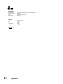
Indicators
Gain Reduction8 segment LED bar graph at 1, 3, 6, 10, 15, 20, 25, and 30 dB
Input/Ouptut Level8-segment LED bar graph at -24, -18, -12, -6, 0, +6, +12, and +18 dBu
Limiter Threshold:
1 LED to indicate PeakStopPlus™ limiting
Function Switches:
LED indicator for each front-panel switch
Specifications
9