1
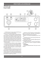
CB01
CB RADIO
Downloaded from www.cbradio.nl
Instrukcja obsługi
User’s Manual
MMRCAM0001 Cyber Eye HD
Cyber Eye HD to stylowe okulary z ukrytą kamerą, pozwalające na dyskretne filmowanie i fotografowanie w doskonałej jakości
HD. Można je wykorzystać jako wygodny aparat do rejestrowania
wyczynów sportowych, do zastosowań prywatnych, rozrywkowych
oraz pracy detektywistycznej. Łatwa obsługa urządzenia za pomocą zaledwie dwóch przycisków, wysokiej jakości lekkie oprawki,
spolaryzowane soczewki dla ochrony oczu oraz dołączony do zestawu futerał ochronny sprawiają, ze Cyber Eye HD sprawdzą się w
każdych warunkach. Okulary zostały wyposażone w pamięć o pojemności 2GB, co wystarcza na zarejestrowanie 50 minut nagrania.
Ponadto urządzenie posiada czytnik kart SD, dzięki czemu można
rozbudować jego pamięć o kolejne 16GB. Sięgnij po Cyber Eye HD
firmy Manta i zaskocz innych tym, co widziałeś…
PMP01 3D Multimedia Player
Manta PMP01 3D Multimedia Player to najnowszy odtwarzacz
multimediów z 8-calowym ekranem o rozdzielczości 1280x768
z technologią 3D niewymagającą okularów! Czytnik obsługuje
wszystkie popularne formaty filmów 3D oraz tradycyjne filmy w
formatach DIVX czy MKV (H.264). Dzięki pamięci własnej (8GB)
oraz czytnikowi kart MMC/SD/SDHC, nowy czytnik błyskawicznie
odtworzy domową kolekcję filmów 3D. Pojemny i wymienny akumulator litowy pozwoli cieszyć się przenośną technologią 3D, jak
również 2D nawet przez 6 godzin bez przerwy. Oprócz odtwarzania
filmów 3D urządzenie pozwala także na wyświetlenie tradycjnych
filmów 2D w popularnych formatach.!
DVBT01 Tuner DVB-T
Tuner DVBT01 DVB-T HD Tuner to nowoczesny tuner telewizyjny firmy Manta Multimedia dedykowany do odbioru kanałów cyfrowej telewizji naziemnej DVB-T w standardzie MPEG-2 i MPEG-4
oraz w rozdzielczości HD. Urządzenie wyposażone jest w komplet
złączy (SCART, komponentowe, kompozytowe, HDMI) umożliwiających podłączenie go zarówno do starszych telewizorów CRT jak
nowszych LCD i plazmowych niewyposażonych w tuner DVB-T. Tuner jest w pełni sterowany z pilota zdalnego sterowania. Wyposażony jest w wyświetlacz LCD informujący o aktualnym kanale telewizyjnym oraz mechaniczny wyłącznik zasilnia. Urządzenie obsługuje wszystkie standardy odtwarzania cyfrowej wizji i fonii używane
w Polsce. Urządzenie jest w pełni kompatybilne z ustawą o telewizji
cyfrowej!
MID04 Multimedia Tablet
MID04 EasyTab to nowoczesny i niedrogi tablet firmy Manta
Multimedia. Urządzenie wyposażone zostało w 7-calowy dotykowy
ekran LCD wykonany w technologii opornościowej. Ekran dotykowy
umożliwia rozpoznawanie gestów zbliżania i oddalania palców, co
pozwala na przykład w prosty sposób sterować powiększeniem wyświetlanego obrazu (na przykład strony WWW, czy mapy). Tablet
MID04 ma wbudowane 4 GB pamięci flash oraz 256 MB pamięci
RAM oraz kamerę internetową. Wbudowaną pamięć można rozszerzyć używając kart MicroSD. Wydajny akumulator o pojemności
2900 mAh zapewnia wiele godzin pracy w terenie. Instrukcja obsługi
CB01
Wprowadzenie............................................................................................................................................................................4
Parametry techniczne.................................................................................................................................................................4
Instalacja........................................................................................................................................................................................4
Położenie....................................................................................................................................................................................4
Montaż i podłączenie.................................................................................................................................................................5
Antena CB......................................................................................................................................................................................5
Regulacja blokady szumów.......................................................................................................................................................5
Tymczasowe używanie..............................................................................................................................................................5
Obsługa..........................................................................................................................................................................................6
Panel Przedni..............................................................................................................................................................................6
Panel tylny...................................................................................................................................................................................7
Odbiór..........................................................................................................................................................................................7
Nadawanie..................................................................................................................................................................................7
Obsługa i regulacja.....................................................................................................................................................................7
Ważne zasady............................................................................................................................................................................8
Użycie radia................................................................................................................................................................................8
Użycie kanału „9”........................................................................................................................................................................8
User’s Manual
Introduction.................................................................................................................................................................................9
Specification.................................................................................................................................................................................9
Installation.....................................................................................................................................................................................9
Location.......................................................................................................................................................................................9
Mounting Connection...............................................................................................................................................................10
CB Antennas...............................................................................................................................................................................10
Ignition Noise Interference.......................................................................................................................................................10
Temporary Mobile Operations.................................................................................................................................................11
Operation.....................................................................................................................................................................................11
Front Panel................................................................................................................................................................................11
Other operation Features.........................................................................................................................................................12
Rear Panel................................................................................................................................................................................12
Operating Procedure to Receive.............................................................................................................................................12
Operating Procedure to Transmit............................................................................................................................................13
Maintenance and Adjustable...................................................................................................................................................13
Important...................................................................................................................................................................................13
How to use................................................................................................................................................................................13
Use Channel 9 For Message Only..........................................................................................................................................13
3
Instrukcja obsługi
Instrukcja obsługi
Napięcie zasilania: 13.8V DC (negatywne uziemienie)
Pobór pracy: Nadawanie: AM pełna moc, 1.5A
Odbiór: (Squelch, 0.115A, pełna moc 1.0A)
Wymiary: 131mm (szer.) x 171mm (dł.) x 44.5 mm (wys.)
Waga: 1.0 kg
Złącze antenowe: UHF,SO-239
Półprzewodnik: 22 tranzystory, 17 diód, 3 połączone
układy, 3 LED
Miernik mocy: Wskazuje konkretną moc wyjściową i siłę
odbieranego sygnału
Wprowadzenie
Częstotliwość pracy
Twoje CB radio jest zgodne z najnowszymi trendami
konstruowania radii CB w Europie.
Kanał
1
2
3
4
5
6
7
8
9
10
11
12
13
14
15
16
17
18
19
20
Częstotliwość
w MHz
26.960
26.970
26.980
27.000
27.010
27.020
27.030
27.050
27.060
27.070
27.080
27.100
27.110
27.120
27.130
27.150
27.160
27.170
27.180
27.200
Kanał
21
22
23
24
25
26
27
28
29
30
31
32
33
34
35
36
37
38
39
40
Częstotliwość
w MHz
27.210
27.220
27.250
27.230
27.240
27.260
27.270
27.280
27.290
27.300
27.310
27.320
27.330
27.340
27.350
27.360
27.370
27.380
27.390
27.400
Nadajnik
Moc wyjściowa: 4 W
Rodzaj modulacji: Wysoki i niski poziom, klasa B
rozpiętości
Częstotliwość: 300 do 3000Hz
Impedancja: 50 ohms, niewyważony
Ochrona: Wyjście radia chronione jest przed niedopasowaniem (20:1)
Odbiornik
Czułość: Mniejsza niż 1 µ V dla 10dB (S+N) /N
Selektywność 6dB
Odrzucenie sąsiedniego kanału: 50dB
Częstotliwość IF: Podwójne przejście,
1: 10.695MHz
2: 455KHz
Automatyczna regulacja wzmocnienia: Mniej niż 10dB,
zmień wyjście w wejście z 10 do 50 000 µ V
Squelch: Regulowany; pułap mniejszy niż 1 µ V
Moc wyjściowa audio: 3 W
Częstotliwość reakcji: 300-3000Hz
Zakłócenie: Mniej niż 10% @ 3 W @ 1000Hz
Wbudowany głośnik: 16 ohms, okrągły
Zewnętrzny głośnik (nie załączony): 8 ohms; wewnętrzny głośnik zostanie wyłączony, gdy zewnętrzny zostanie
podłączony
Częstotliwości te są generowane przez pętlę synchronizacji fazy.
W celu uzyskania maksymalnej wydajności, uważnie
przeczytaj opis oraz użytkowanie urządzenia.
System megafonu (PA)
Moc wyjściowa: 4 W w zewnętrznym głośniku
Zewnętrzny głośnik megafonu: 8 ohms; należy zaopatrzyć
się w dodatkowe gniazdo
Parametry techniczne
Ogólne
Kanał 40
Częstotliwość pracy: 26.960 do 27.400MHz
Stabilizacja częstotliwości: Pętla synchronizacji fazy,
syntezator
Tolerancja częstotliwości: 0.005%
Temperatura pracy: -30°C do + 50°C
Mikrofon: Elektretowy kondensator
Instalacja
Położenie
Wybierz miejsce montażu nadajnika i mikrofonu w łatwo
dostępnym miejscu. Przeważnie radiotelefon montowany
jest pod deską rozdzielczą.
4
Instrukcja obsługi
Montaż i podłączenie
Podczas instalacji na łodzi, CB nie będzie działało z maksymalną wydajnością bez uziemienia, chyba że łódź jest
wyposażona w metalowy kadłub. Przed instalacją radia CB
należy skontaktować się ze sprzedawcą w celu uzyskania informacji odnośnie elektroliz pomiędzy kadłubem a wodą.
Trzy rodzaje anten jest dostępnych, które pozwalają na
użytkowanie trzech pasm (AM,FM i CB). Antena „Single
Band” jest przeznaczona do CB radia.
W zestawie do montażu znajduje się uniwersalna klamra
do montażu wraz ze śrubami umożliwiającymi przykręcenie
CB radia pod odpowiednim kątem.
1. Ustaw CB radio w klamrze i dopasuj ją w porządanym
miejscu w samochodzie. Następnie wyjmij samo radio, a
miejsca dziur w klamrze oznacz markerem.
2. Wywierć dziury w oznaczonych miejscach i przymocuj
klamrę śrubami.
Regulacja blokady szumów
Szczególnie w modulacji FM szum na wolnym kanale
może być niezwykle uciążliwy.
Pokrętłem blokady szumów możesz skasować hałas ale
również i słabsze sygnały od dalekich
korespondentów.
Twój radiotelefon wyposażony jest w funkcję automatycznej regulacji i blokady szumów.
Tymczasowe używanie
W celu tymczasowego użycia radiotelefonu, należy podłączyć zapalniczkę samochodową.
3. Przykręć wtyk antenowy do gniazda antenowego w CB
radiu. Większość anten jest zakończona wtyczką typu PL259, którą należy włożyć do miejsca oznaczonego „ANT”
4. Połącz czerwony przewód radia z dodatnim biegunem
akumulatora lub innym miejscem instalacji elektrycznej,
gdzie jest ciągle obecny „+” lub do +13.8V DC voltowego
reduktora napięcia. Przed przystąpieniem do instalacji należy
sprawdzić wizualnie gdzie znajduje się końcówka baterii
(pozytywna lub negatywna).
5. Podłącz czarny przewód zasilania z ujemnym biegunem akumulatora lub reduktorem napięcia, albo z dobrze
przewodzącą częścią nadwozia.
6. Podobnie jak klamrę, przytwierdź uchwyt na mikrofon,
pamiętając o łatwym dostępie do mikrofonu. Włóż i dokręć
wtyk mikrofonu o gniazda CB z przodu panelu.
Antena CB
Połączenie pomiędzy anteną a kablem, należy wykonać
dobrym jakościowo przewodem koncentrycznym 50-ohm.
Krótka antena wygląda bardziej atrakcyjnie lecz nie przekłada się to na maksymalny odbiór.
Standardowy łącznik anteny CB (typ SO-239) łatwo jest
połączyć ze standardowym kablem PL 259.
5
Obsługa
Instrukcja obsługi
Panel Przedni
1. Off/On/Głośność. Przekręć gałkę ON-OFF/Volume
zgodnie z kierunkiem wskazówek zegara.
2. Squelch. Funkcja ta pozwala na wyeliminowanie zakłóceń słyszalnych na kanałach CB. Aby poprawnie ustawić
poziom squelch, kręć pokrętłem dotąd, aż wszystkie słyszalne dźwięki zostaną wyciszone. Jedynie sygnały o sile
wyższej niż ustalony squelch „przebiją” się przez blokadę.
Jest to gwarancja na odbieranie mocnych, wyraźnie słyszalnych komunikatów. Uważaj, aby poziom squelch nie był
zbyt wysoki, ponieważ ilość sygnałów które będą słyszalne
drastycznie spadnie.
3. Gniazdo mikrofonowe. Mikrofon musi być połączony
przez cały czas z zespołem w celu poprawnego działania.
4. Szybki kanał 9. Używany jest, aby przełączyć się między szybkim dostępem do kanałów „9”. Ustawienie NORMAL powraca do normalnego trybu zmiany 40 kanałów
przyciskami UP/DOWN.
5. CB/PA. W pozycji CB funkcja PA jest wyłączona a radio
będzie nadawało i odbierało na aktualnym kanale. Funkcja
PA powinna być uruchamiana tylko przy podłączonym zewnętrznym głośniku. Przy włączonej funkcji PA nadawanie
jest zablokowane a wyjście mikrofonowe podaje sygnał
bezpośrednio do zewnętrznego głośnika.
6. Miernik mocy S-RF. Pokazuje moc wyjściową RF nadajnika oraz siłę sygnału odbieranego. Na wyświetlaczu
pojawią się segmenty zależne od siły sygnału.
Dioda TX. W momencie nadawania pojawi się ikona
„TX”
7. Wyświetlacz kanału. Numer aktywnego kanału wskazany jest na wyświetlaczu.
8. Wybór kanału. Wybór z 40 kanałów odbywa się poprzez
kręcenie gałką w obie strony.
9. Szybka zmiana kanału – przyciśnij i przytrzymaj przycisk „ UP and Down”. Pozwoli to na przejście 40 kanałów
w 6 sekund.
Inne funkcje
Automatyczne zakłócanie hałasu. Funkcji tej nie można
wyłączyć.
6
Panel tylny
Instrukcja obsługi
Nadawanie
1. Gniazdo antenowe. Łącznik SO-239 pozwala na przyłączenie anteny do CB radia.
2. Gniazdo megafonu. Zewnętrzny 8 –ohm 4 W PA głośnik
może być przyłączony do PA gniazda głośnika. Głośnik
powinien być skierowany w przeciwną stronę od mikrofonu
aby uniknąć „echa”.
3. Gniazdo zewnętrznego głośnika. Zewnętrzny głośnik
powinien posiadać opór 8 ohm i być przystosowany do operowania 4 W. Podczas gdy zewnętrzny głośnik jest włączony,
zewnętrzny zostanie automatycznie wyłączony.
4. Zasilanie. Kable zasilające. Patrz- INSTALACJA
1. Wybierz pożądany kanał
2. Wciśnij przycisk PTT i mów do mikrofonu z odległości
ok. 10 cm normalnym głosem. Aby otrzymać odpowiedź,
puść przycisk PTT.
Przed nadawaniem upewnij się, że antena, kabel antenowy jest solidnie przymocowany do gniazda antenowego
z tyłu radia CB.
Używanie radiatelefonu / megafon
Przyłącz głośnik do gniada PA z tyłu panelu
Ustaw CB/PA przycisk w pozycji PA
Przyciśnij i przytrzymaj przycisk w mikrofonie. Mów normalnym głosem
Ustaw głośność używając pokrętła VOLUME z przodu
CB radia.
Odbiór
1. Upewnij się, że wszystkie elementy zestawu są prawidłowo podłączone a przycisk CB/PA ustawiony jest w
pozycji CB. Przycisk kanału 9/NOR powinien być położony
w pozycji NOR.
2. Włącz radiotelefon.
3. Ustaw poziom squelch do optymalnej wartości.
4. Wybierz pożądany kanał przekręcając gałką CHANNEL SECTOR.
5. Ustaw głośność.
Dostosuj SQUELCH tak aby jakość odbioru była
optymalna.
Obsługa i regulacja
Radiotelefon jest specyficznie zaprojektowany do wnętrza
samochodu.
1. Sprawdź połączenie kabli zasilających. Upewnij się, że
radio posiada wymagane 13.8V DC zasilania.
2. Sprawdź bezpiecznik przy kablu zasilającym. Kabel
zasilający (czerwony) w typie 3AG posiada 2Amp.
3. Upewnij się czy mikrofon jest właściwie podłączony.
4. Upewnij się czy antena jest poprawnie zestrojona i
podłączona.
7
Instrukcja obsługi
Ostrzeżenie
Naruszenie przepisów FCC, część 95 lub rodzaju akceptacji, część 2, są związane z użyciem części zamiennych
(są one nie rekomendowane przez nas).
NIE – „Ruch na drodze w stronę Beltway jest płynny”
TAK – „Stacja meteorologiczna ogłosiła stan zagrożenia
burzowego. Należy sprowadzić wszystkie łodzie do portu”
NIE – „ Do wszystkich motorzystów! Stacja meteorologiczna przestrzega przed opadami śniegu w dniu jutrzejszym.
Może spaść od 10 do 15 cm. śniegu”
TAK – „Wybuchł pożar na rogu ul. 6tej i MAIN
NIE – „Tu patrol nr 3 HALLOWEEN. U mnie wszystko
w porządku”
Ważne zasady
1. Nie jest wskazane prowadzenie rozmowy ponad 5 min
bez zrobienia 1 minutowej przerwy
2. Praca CB radia nie może zakłócać sygnału innych
użytkowników przez używanie anten niewiadomego pochodzenia lub bardzo dużych
3. CB radio nie może być używane do nielegalnych
aktywności
4. Używając radia nie wolno używać przekleństw
5. Nie należy odtwarzać muzyki w CB radiu
6. Niedopuszczalne jest używanie CB radia do prowadzenia działalności gospodarczej
Uwaga!
Konstrukcja produktu i parametry techniczne mogą ulec
zmianie bez wcześniejszego powiadomienia. Dotyczy to
przede wszystkim parametrów technicznych, oprogramowania, opakowania oraz podręcznika użytkownika. Niniejszy podręcznik użytkownika służy ogólnej orientacji dotyczącej obsługi produktu.
−− Produkt oraz akcesoria do urządzenia mogą się różnić
od tych opisanych w instrukcji.
−− Producent i dystrybutor nie ponoszą odpowiedzialności
tytułem odszkodowania za jakiekolwiek nieścisłości wynikające z błędów w opisach występujących w niniejszej
instrukcji użytkownika.
Użycie radia
−− Ostrzeganie o utrudnieniach na drodze
−− Dostarczanie informacji pogodowych
−− Informacje o potrzebnej pomocy
−− Sugestie odnośnie noclegów, postojów, itp.
−− Długie podróże mogą być bardziej ciekawe
−− Bezpośredni kontakt z biurem lub domem
−− Nawiązywanie przyjaźni w czasie podróży
−− Informacje o twojej lokalizacji w celu znalezienia
twojej osoby na trasie
−− Ostrzeganie przed pijanymi lub nieostrożnymi
kierowcami
Użycie kanału „9”
Poniżej przedstawione są dozwolone i niedozwolone typy
komunikacji na kanale nr.9
Dozwolone/niedozwolone:
Przykłady
TAK – „Tornado znajduje się 15km na północ od
miasta”
NIE – „Tu punkt obserwacyjny nr.10. Tornado jest w
zasięgu wzroku”
TAK – „Znajduję się na drodze krajowej nr 95. Na 12 km
skończyło mi się paliwo”
NIE – „Skończyło mi się paliwo na drodze szybkiego
ruchu”
TAK – „Kolizja czterech samochodów na drodze wyjazdowej nr10 na Beltway. Proszę przysłać policję i karetkę
pogotowia”
8
User’s Manual
User’s Manual
Frequency Tolerance: 0.005%
Operating Temp. Range: -30°C do + 50°C
Microphone: Plug-in type; Electret condenser
Input Voltage: 13.8V DC nom. (negative ground)
Current Drain Transmit: AM full mod., 1.5A (maximum).
Receive: (Squelched, 0.115A, full audio output 1.0A
(normal)
Size: 131mm(D)×171mm(W)×44.5mm(H)
Weight: 1.0Kg
Antenna Connector: UHF, SO-239
Semiconductors: 22 transistors, 17 diodes, 3 integrated
circuits,3 LEDs.
Meter Indicates relative power output and received signal
strength
Transmitter
Power Output: 4 watts
Modulation: High- and low-level Class B amplitude
Frequency: 300 to 3000Hz
Output Impedance :50 ohms, unbalanced
Output Protection: Output transistors protected against
mismatch up to 20:1
Receiver
Sensitivity Less than 1 µ V dla 10dB (S+N) /N
Selectivity: 6dB typical
Adjacent CH: Rejection 50dB typical
IF Frequency Double conversion:
1st: 10.695 MHz
2st: 455KHz
Automatic Gain Control (AGC): Less than 10dB change
in audio output for inputs from 10 to 50,000μV
Squelch Adjustable: threshold less than 1μV
Audio Output Power: 3 watts
Frequency Response: 300-3000Hz
Distortion: Less than 10% @ 3 watts @ 1000Hz
Built-in Speaker: 16 ohms, round
External Speaker: 8 ohms; disable internal speaker when
connected (Not Supplied)
PA System
Power Output 4 watts into external speaker
External Speaker for PA 8 ohms; a separate jack is provided (Not Supplied).
Introduction
Frequency Range
Your CB radio Provides high-level, trouble-free performance over the following frequency assignments:
Channel Frequency
in MHz
1
26.960
2
26.970
3
26.980
4
27.000
5
27.010
6
27.020
7
27.030
8
27.050
9
27.060
10
27.070
11
27.080
12
27.100
13
27.110
14
27.120
15
27.130
16
27.150
17
27.160
18
27.170
19
27.180
20
27.200
Channel Frequency
in MHz
21
27.210
22
27.220
23
27.250
24
27.230
25
27.240
26
27.260
27
27.270
28
27.280
29
27.290
30
27.300
31
27.310
32
27.320
33
27.330
34
27.340
35
27.350
36
27.360
37
27.370
38
27.380
39
27.390
40
27.400
These frequencies generated and accurately controlled
by a phase lock hoop (PLL) circuit, comprised of the latest
state-of-the-art integrated circuit technology, ensuring high
reliability and excellent frequency stability on the above
channels.
To obtain maximum performance please read carefully the
descriptions and operating instructions in this manual.
Specification
Installation
General
Channels: 40
Frequency Range: 26.960 to 27.400MHz
Frequency Control: Phase-Locked Loop (PLL)
synthesizer
Location
Plan the location of the transceiver and microphone
bracket before starting the installation. Select a location
9
User’s Manual
that is convenient for operation and does not interfere with
the driver or passengers in the vehicle. In automobiles, the
transceiver is usually mounted to the underneath of the dash
panel, with the microphone bracket beside it.
Mounting Connection
The transceiver is held in the universal mounting bracket
by two thumb screws, permitting adjustment at the most
convenient angle.
A universal mounting bracket is supplied along with self
tapping screws and star washers. The mounting must be
mechanically strong and also provide a good electrical
connection to the chassis of the vehicle. To mount the
transceiver:
1. Determine the most convenient location in your vehicle.
Hold the Supernova radio with mounting bracket in the exact
location desired. If nothing will interfere with mounting it in the
desired position, remove the mounting bracket and use it as
a template to mark the location for the mounting screws.
2. Drill necessary holes and secure mounting bracket
in location.
3. Connect the antenna cable plug to the standard receptacle on the unit. Most CB antennas are terminated
with a type PL-259 plug which mates with the receptacle
marked „ANT.”
4. Connect the red lead of DC power cord to +13.8VDC.
In automobile installations, +13.8VDC is usually obtained
from the accessory contact in the fuse box. This prevents
the set being left on accidentally and also permits operating
the unit without the vehicle’s engine running. Before installing
the CB radio, visually check the vehicle battery connections
to determine which battery terminal, positive or negative
(positive is the larger of the two) is grounded to the engine
block (or chassis).
5. Connect the black lead to the negative side of the
automobile. This is usually the chassis of the car. Any convenient location with good electrical contact (remove paint)
may be used.
6. Mount the microphone bracket on right side of the
transceiver, or near it using two screws supplied. When
mounting in an automobile, place the bracket under the dash
so the microphone is readily accessible.
CB Antennas
Only a properly matched antenna system will allow maximum power transfer from the 50-ohm transmission line to
the radiating element. In mobile installations (cars, trucks,
boats, etc.), an antenna system that is non-directional should
be used.
A vertically polarized, quarter-wavelength whip antenna
provides the most reliable operation and greatest range.
The shorter, loaded-type whip antennas are more attractive,
compact and adequate for applications where the maximum
possible distance is not required. Also, the loaded whips do
not present the problems of height imposed by a full quarterwavelength whip.
Mobile whip antennas utilize the metal body of the vehicle as a ground plane. When mounted at a corner of the
vehicle they are slightly directional, in the direction of the
body of the vehicle. For all practical purposes, however,
the radiation pattern is nondirectional. The slight directional
characteristic will be observed only at extreme distances. A
standard antenna connector (type SO-239) is provided on
the transceiver for easy connection to a standard PL 259
cable termination.
When installed in a boat, the transceiver will not operate
at maximum efficiency without a ground plate, unless the
vessel has a steel hull. Before installing the transceiver in a
boat, consult your dealer for information electrolysis between
fittings in the hull and water.
3-Way Combinations Antennas are available which allow
operation of all three bands (AM-FM & CB), using a single
antenna.
Ignition Noise Interference
Use of a mobile receiver at low signal levels is normally limited by the presence of electrical noise. The primary source
of noise in automobile installations is from the alternator and
ignition system in the vehicle. Under most operating conditions, when signal level is adequate, the background noise
does not present a serious problem. Also, when extremely
10
User’s Manual
low level signals are being received, the transceiver may be
operated with vehicle engine turned off. The unit requires
very little current an therefore will not significantly discharge
the vehicle battery.
Even though the supernova radio has an automatic noise
limiter, in some installations, ignition interference and other
forms of automobile generated noise may be high enough
to make good communications difficult. The electrical noise
may come from several sources. Many possibilities exist
and variations between vehicles require different solutions
to reduce the noise. Consult your supernova dealer or a
2-way radio technician for help in locating and correcting
the source of severe noise.
Temporary Mobile Operations
To operate your supernova transceiver from a car on a
temporary basis, you may want to purchase an optional cigar
lighter adapter from your supernova dealer. This adapter and
a magnetic mount antenna allow you to quickly „install” your
transceiver for temporary use.
Operation
1. Off/On/Volume. Turn clockwise to turn power on and
set the desired listening volume.
2. Squelch. This control is used to cut off or eliminate
receiver background noise in the absence of an incoming
signal. For maximum receiver sensitivity, it is desired that
the control be adjusted only to the point where the receiver
background noise or ambient background noise is eliminated.
Adjust until the receiver noise disappears. This will require
the incoming signal to be slightly stronger than the average
receiver noise. Further clockwise rotation will increase the
threshold level which a signal must overcome in order to
be heard. Only strong signals will be heard at a maximum
clockwise setting.
3. Microphone Connector. This front mounted, screw-on
connector allows for convenient removal of the microphone
plug when storage is required. The microphone MUST be
connected to the unit at all times when in use, for proper
operation. The screw-on connection enhances the life of
the microphone cord as well.
4. Channel 9/Normal Switch. Used for instant selection
of emergency channel 9 (CH.9 position). In NOR position,
all 40 CB channels are selected by the UP/DOWN CHANNEL BUTTONS.
Front Panel
11
User’s Manual
5. CB/PA Switch. Selects mode of operation. In the CB
position, the PA function is disabled and the unit will transmit
and receive on the selected channel, The PA function should
not be used 7 unless a PA speaker is connected.
6. S-RF/Power Meter. Shows relative transmitter RF output
power and input signal strength when receiving. The five LED
(Light Emitting Diode) segments glow to indicate receive or
transmit activity.
7. TX Indicator. This indicator will light red when in the
transmit mode.
8. Channel Display. The selected operating channel will
be displayed here.
9. Channel Selector Switch. When turned, this knob is
used to select any one of the forty citizens band channels
desired.
Other operation Features
Automatic Noise Limiter. This is a non-switchable feature
that is always on to reduce background noise.
Rear Panel
3. EXTERNAL SPEAKER: The External Speaker Jack is
used for remote receiver monitoring. The external speaker
should have 8 ohms impedance and be rated to handle at
least 4.0 watts. When the external speaker is plugged in, the
internal speaker is automatically disconnected.
4. POWER: These wires supply power to the CB radio.
See page 5 for installation.
Operating Procedure to Receive
1. Be sure that the power, antenna and microphone are
properly connected before proceeding further. The CB/
PA switch should be in the CB mode. The Channel 9/NOR
Switch should be in the NOR mode.
2. Turn the radio ON by rotating the VOLUME CONTROL
clockwise.
3. Rotate SQUELCH CONTROL counterclockwise until
incoming signal is heard.
4. Turn the CHANNEL SELECTOR KNOB to select the
desired operating channel.
5. Set the VOLUME CONTROL to a comfortable listening level.
1. ANTENNA CONNECTOR: This SO-239 connector
permits connection of the transmission line cable male
connector to the transceiver.
2. PUBLIC ADDRESS: An external 8-ohm 4.0 watt PA
speaker may be connected to the PA Speaker Jack when
this unit is used as a public address system. The speaker
should be directed away from the microphone to prevent
acoustic feed-back. Physical separation or isolation of the
microphone and speaker must be employed when operating
the PA at high output levels.
12
User’s Manual
Operating Procedure to Transmit
1. Select the desired channel.
2. Press PTT and Talk Switch. The receiver and transmitter
are controlled by the press-to-talk switch on the microphone.
Press the switch and the transmitter is activated; release
switch to receive. When transmitting, (on a clear channel),
hold the microphone two inches from the mouth and speak
in a clearly normal voice.
Be sure the antenna is properly connected to the radio
before transmitting. Prolonged transmitting without an antenna, or a poorly matched antenna, could cause damage
to the transmitter.
Maintenance and Adjustable
Your CB transceiver is specifically designed for the environment encountered in mobile installations. The use of all
solid state circuitry and its light weight result in high reliability.
Should a failure occur, however, review the following, then
if necessary replace parts only with identical parts. Do not
substitute. Refer to the schematic diagram and parts list.
1. Check connections to the source of power and make
sure it is the 13.8 VDC required to operate your radio.
2. Check the fuse in the DC power cord. The main power
lead (red wire) has a 2 Amp 3 AG type fuse installed. Use
only the above specified type and size fuse for maximum
protection. Failure to do so will void the warranty.
3. Make certain the microphone is properly plugged in.
4. Make certain the antenna is properly connected and
tuned for mini-mum SWR.
Important
1. You are not allowed to carry on a conversation with
another station for more than five minutes at a time without
taking a one-minute break, to give others a chance to use
the channel.
2. You are not allowed to blast others off the air by overpowering them with illegally amplified transmitter power, or
illegally high antennas.
3. You can’t use CB to promote illegal activities.
4. You are not allowed to use profanity.
5. You may not play music in your CB.
6. You may not use your CB to sell merchandise or professional service.
−− Provide help fast in event of emergency or
breakdown.
−− Suggest good spots to eat and sleep.
−− Make long trips more interesting, and help keep you
awake.
−− Provide direct contact with your office or home.
−− Make friends for you as you travel.
−− Provide „local information” to find your destination.
−− Help law enforcement officers by reporting drunk and
reckless drivers.
Use Channel 9 For Message Only
FCC give the following examples of permitted and prohibited types of communications for use on Channel 9. These
are guidelines and are not intended to be all-inclusive.
Permitted:
Example Message:
Yes – “A tornado sighted six miles north of town.”
No – “This is observation post number 10. No tornado
Sighted.”
Yes – “I am out of gas on Interstate 95 at mile marker
121
No – “I am out of gas in my driveway.”
Yes – “There is a four-car collision at Exit 10 on the Beltway, send police and ambulance.”
No – “Traffic is moving smoothly on the Beltway.”
Yes – “Base to unit 1, the Weather Bureau has just issued
a thunderstorm warning. Bring the sailboat into port.”
No – “Attention all motorists. The Weather Bureau advises
that the snow tomorrow will accumulate 4 to 6 inches.”
Yes – “There is a fire in the building on the corner of 6th
and Main Streets.”
No – “This is Halloween patrol unit number 3. Everything
is quiet here.”
How to use
−− Warn of traffic tie-ups ahead.
−− Provide weather and road information.
13
note
14
note
15
Dział Obsługi Klienta
tel: +48 22 332 34 63 lub e-mail: [email protected]
od poniedziałku do piątku w godz. 9.00-17.00
Producent zastrzega sobie możliwość wprowadzenia zmian w specyfikację produktu bez uprzedzenia.
Made in P.R.C.
FOR MANTA EUROPE