1
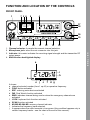
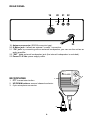
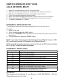
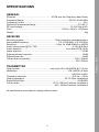
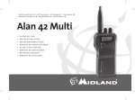
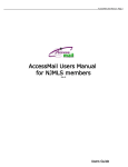
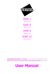
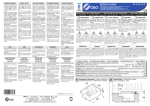
®
40 KAN
40 CAN ÄLE AM/FM
ALI AM
/FM
ALAN 4
8 EXCE
40 AM
/F
40 CAN M - CHANNEL
S
40 CAN ALES AM/FM
AUX AM
/FM
L
MANUALE ISTRUZIONI - USER'S MANUAL
MANUEL D'UTILISATION - MANUAL DEL USUARIO
ALAN 48 EXCEL
INDEX
Introduction............................................................................................ 2
Function and location of the controls..................................................... 3
Installation............................................................................................. 7
Power supply...................................................................................... 7
Installing an antenna.......................................................................... 7
How to use your ALAN 48 EXCEL MULTI............................................. 8
Frequency band selection.................................................................. 8
Frequency band chart......................................................................... 8
E N G L I S H
Specifications........................................................................................ 9
Important Note
Following national regulations have been modified:
Residents of Belgium, Great Britain, Spain and Switzerland need a
CB licence in their countries, while visitors may use their CB radios in
FM free of licence, for AM they should be able to present their homecountry’s licence document. In Italy, even visitors need a valid Italian
authorization.
Austria does not accept any multi-standard or programmable CB radio.
Please respect this requirement and do not use Your radio during driving
through Austria.
In Germany transmitting as a base station on channels 41-80 is restricted
in some areas along the country borders. No restrictions apply for
mobile use. More details can be obtained from the local RegTP authority
office.
Changes in European or national regulations will be published on the
service website of ALAN-Albrecht under www.alan-albrecht.info
ALAN 48 EXCEL MULTI is a mobile transceiver whose main feature is
the possibility to select any of the European CB bands with an easy and
quick operation. ALAN 48 EXCEL MULTI is equipped with the “ESP2”
(noise reducer device) that reduces considerably the audio noises
up to 95%, allowing a clear communication even when the signal is
disturbed.
The wide multifunctional backlit display shows the number of the channel
in use or the correspondent frequency even in conditions of deep
darkness. ALAN 48 EXCEL MULTI is also equipped with an analogical
S-Meter, showing the transmitted power and the signal received, and
with the exclusive internal voltage reducer allowing the use with 12V or
24V power supply. The unit is preset at the factory on the “EC“band , CEPT 40CH FM 4W.
FUNCTION AND LOCATION OF THE CONTROLS
FRONT PANEL
7 3 6
5
4
VOL
CH
01
0
3
2
17
18
5 7 9 30
3 5 10
POWER
EMG
F
MIC
CB/PA
FUNC
2
8
SQ
TX
RX AM
M1
EMG
9
LOW
ESP
LOCK DW SCAN
MIC
RF
FM
M2
DW
M3
SCAN
10
M4/LCR
AM/FM
M5
LOCK
N.K.
12
13
14
11
16
15
1. Channel selector: it permits the manual channel selection.
2. Microphone jack: insert the mic connector into this jack.
3. Indicator: this meter indicates the receiving signal strength and the transmitter RF output power.
4. Multifunction backlighted display.
a
i
h
b
F
EMG
LOW
ESP
e
j
c
LOCK DW SCAN
f
d g
It shows:
a. channel selected number (from 1 up 40) or operative frequency
b. FUNC button activated
c. ESP: reducing noise device activated
d. DW: Dual Watch function activated e. EMG: indicates channel being used or when the emergency channels are activated
f. LOCK: keyboard lock function activated
g. SCAN function activated
h. M1-M2-M3-M4-M5: memory channel indicator
i. Indicates the frequency band selected.
j. It appears when the radio transmits in low power (this condition happens only in
certain frequency bands – see the chart at the end of this manual).
E N G L I S H
1
5. “AM/FM” Indicator
It indicates the operative mode. FM: red LED; AM: green LED.
6. “RX/TX” Indicator
LED indicating receiving or trasmitting mode. RX: green LED; TX: red LED.
7. “CB/PA” Selector
In the “CB” position, the unit operates as a transceiver. You can use the PA (public
address) function only if you connect a speaker to the PA jack (“PA” visualized on
the display). In this case the “MIC” knob controls the amplification level.
8. FUNC button
With the SCAN button, you can:
• visualize the operative frequency (if you keep pressing the button for 3 seconds
approx.), or the channel in use;
• activate the second functions of the “M” (M1/M5) buttons.
M1 / M2 / M3 / M4 / M5:
ALAN 48 EXCEL has the possibility to store and to recall, when necessary, 5
channels previously memorized.
To memorize one channel, follow the procedure herebelow:
A) Select the channel with the appropriate selector or the “UP/DN” buttons on the
microphone;
B) Push the “FUNC” button: the display will show “F”;
C) Keep pressing the “M1/EMG” button for 3 seconds: you will hear a “BIP” and the
display will show “M1”.
To memorize the other preset, repeat these steps and select another memory
different from 1.
To recall a channel previously stored, push the “FUNC” switch and the button of the
desired memory.
These buttons have two functions; herebelow you will find their descriptions:
9. “M1 - EMG” switch
This switch allows the storing of the first memory and the recalling of the 2 emergency
channels. “M1 - EMG” selects sequentially channels 9 / 19 (emergency) and the one
in use. 10.“M2 - DW” button
“M2 - DW” stores the chosen channel in the M2 memory and activates the DUAL
WATCH. This function allows the synthonization on two different channels at the
same time:
when a signal on the second channel is received, the conversation on the first one
is automatically interrupted and the receiver switches on the second channel. The
monitoring starts again 5 seconds after the signal end.
To activate this function, operate as follows:
- Select the desired channel through the channel selector or the “UP/DOWN”
buttons on the microphone;
- Keep the “DW” button pressed for about 3 seconds: you will hear a “BIP” and
“DW” will flash on the display.
- Select the second channel with the same procedure;
- Press the button “DW” again for roughly 3 seconds: you will hear another “BIP”;
the display will permanently show “DW” and will alternatively visualize the two
selected channels.
11.“M3 - SCAN” switch
The two functions of this button are: memorization of the third channel in the M3
E N G L I S H
memory and “SCAN” function activation. In this case, you can automatically seek
for a busy channel:
• turn the squelch clockwise until the background noise is no longer heard;
• press the “M3 - SCAN” button: “SCAN” will be shown on the display and the
transceiver will automatically scan all the channels until a carrier is being
received.
This function can be deactivated in three ways: pressing the PTT button, turning the
channel selector or simply pushing any other button on the unit.
12.“M4/LCR - AM/FM” button
Stores the memory number 4 and selects the operative mode (AM/FM). AM: green
LED; FM: red LED. If you select a frequency band operating in FM modulation only,
this button activates the LCR function (Last Channel Recall).
13.“M5 - LOCK” switch
Pressing this button, you memorize the fifth (last) memory and activate the “LOCK”
function (it allows the locking of the keyboard, channel selector and “UP/DN” buttons
on the microphone, thus avoiding accidental use of the keys).
14.N.K. button
Pressing this switch, you activate the reducing noise device (see introduction).
15.“MIC” knob
The amplification of the voice in TX must be adjusted with this knob. The optimum
level of the modulation must be found with the help of your receiving partner.
16. “RF” knob
It controls the reception sensitivity.
To increase sensitivity, simply turn it clockwise. Sensitivity decreases turning it
counterclockwise.
17.“VOL” knob
It allows the switching on of the unit and sets the volume to a comfortable audio
level.
18.“Squelch” knob
For the maximum receiver sensitivity, the control must be regulated exactly where
the receiver background noise disappears.
REAR PANEL
19
20
21
22
S-METER
PA
EXT
ANTENNA
23
19.Antenna connector (SO239 connector type).
20. S.Meter jack: it allows an external “s meter” connection.
21. “PA” jack: by connecting with an external loudspeaker, you can use the unit as an
audio-amplifier.
22.”EXT” jack: external loudspeaker jack (the internal loudspeaker is excluded).
23. Power 13.2 Vdc: power supply cable.
MICROPHONE
UP
1
1. PTT: transmission button
2. UP/DOWN buttons: manual channels selector.
3.6 pin microphone connector.
DOWN
3
2
INSTALLATION
Safety and convenience are the primary consideration for mounting any piece of mobile
equipment. All controls must be readily available to the operator without interfering with
the movements necessary for safe operation of the vehicle. Set the proper position in
the car to install the transceiver using the supplied supporting bracket or eventually the
slide bracket. Tighten the retaining screws. The fixing bracket must be close to metallic
parts.
POWER SUPPLY
Be sure the transceiver is off. In the direct-voltage power supply, to observe the polarity
is very important, even if the unit is protected against the accidental inversion:
Red = positive pole (+)
Black = negative pole (-)
The same colors are present on the battery and in the fuse box of the car. Connect
correctly the cable terminal to the battery.
INSTALLING AN ANTENNA
1.
2.
3.
4.
Place the antenna as high as possible.
The longer is the antenna, the better will be the performance.
If possible, mount the antenna in the center of whatever surface you choose.
Keep the antenna cable away from noise sources, such as the ignition switch,
gauges,etc.
5. Make sure you have a solid metal-to-metal ground connection.
6. Prevent cable damage during antenna installation.
WARNING. to avoid damage, never operate your CB radio without connecting a
proper antenna. A periodical control of the SWR is recommended.
E N G L I S H
ATTENTION
To obtain best performances we recommend to install the radio in a place with
enough air circulation.
HOW TO OPERATE WITH YOUR
ALAN 48 EXCEL MULTI
1.
2.
3.
4.
5.
6.
7.
Screw the microphone plug into the microphone jack.
Make sure your antenna is securely connected to the antenna connector.
Make sure the SQUELCH control is turned fully conterclockwise.
Turn on the unit and adjust the volume control.
Select your desired channel through the “UP/DN” buttons on the microphone.
To transmit, press the PTT button and speak with a normal tone of voice.
To receive, release the PTT button.
FREQUENCY BAND SELECTION
The frequency bands must be chosen according to the country you are in. Procedure:
1. Switch off the unit.
2. Turn it on while pushing the “N.K.” button. 3. Rotate the “CHANNEL” knob and select the desired frequency band (see the chart
here below).
4. To fix your selection, press the “LOCK” button.
NOTE: If you select a frequency band which operates in FM mode only, the “AM/
FM” control activates the LCR function (Last Channel Recall).
NOTE: In the UK frequency band, you can select directly the EC band by pushing
the “LCR-A/F” control for about 2 seconds.
FREQUENCY BAND CHART
Displayed digits
Country
I
Italy 40 CH AM/FM 4Watt
I2
Italy 34 CH AM/FM 4Watt
D
Germany 80 CH FM 4Watt / 12 CH AM 1 Watt
D2
Germany 40 CH FM 4Watt / 12 CH AM 1 Watt
EU
Europe 40 CH FM 4Watt / 40 CH AM 1 Watt
EC
CEPT 40 CH FM 4Watt
E
Spain 40 CH AM/FM 4Watt
F
France 40 CH FM 4Watt / 40 CH AM 1 Watt
UK
England 40 CH FM 4Watt English frequencies +
+ EC 40 CH FM 4Watt CEPT frequencies
ATTENTION!
The frequency band allowed all over Europe is 40CH FM 4W (EC) – See the
“Restrictions on the use” table.
SPECIFICATIONS
GENERAL
Channels .......................................................... 40 FM (see the Frequency band chart)
Frequency Range . ...........................................................................25.615-30.105 MHz
Frequency Control . ...................................................................................................PLL
Operating Temperature Range......................................................................-10°/+55° C
DC input voltage . ............................................................................... 13.2/24 Vdc ±15%
Size...................................................................................... 150(L) x 45(H) x 175(D)mm
Weight........................................................................................................................1Kg
Receiving system.......................................................Dual conversion superheterodyne
Intermediate frequency ..................................................I°IF:10.695 MHz II°IF:455 KHz
Sensitivity.................................................................... 0.5µV for 20dB SINAD in AM/FM
Audio output power @10% THD............................................................ 2.0 W @ 8 Ohm
Audio distortion............................................................................Less than 8% @ 1KHz
Image rejection.........................................................................................................65dB
Adjacent channel rejection.......................................................................................65dB
Signal/Noise ratio.....................................................................................................45dB
Current drain at stand/by........................................................................... 13.2V: 450mA
..................................................................................................................... 24V: 520mA
TRANSMITTER
Output power.....................................................duty cycle 10% 4W AM/FM @ 13.2 Vdc
Modulation....................................................................................... FM:1.8KHz ± 0.2khz
.............................................................................................................. AM: 85% to 95%
Frequency response................................................................................400 Hz ÷ 3 KHz
Output impedance......................................................................RF 50 Ohm unbalanced
Signal/Noise Ratio..........................................................................................40 dB MIN
Current drain.........................................................13.2V: 1300 mA (without modulation)
..................................................................................24V: 1600mA (without modulation)
All specifications are subject to change without notice.
E N G L I S H
RECEIVER