1
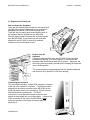
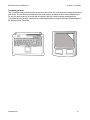
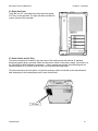
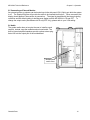
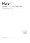
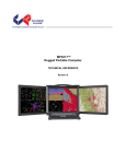
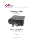
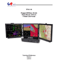
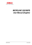
MP1X20A™ Rugged Portable Computer TECHNICAL REFERENCE Revision A MP1X20A Technical Reference Warranty The following is an abbreviated version of Chassis Plans’ warranty policy for portable products. For a complete warranty statement, contact Chassis Plans or visit our website at www.chassis-plans.com. Chassis Plans Portable Computing products are warranted against material and manufacturing defects for 1 (one) year from date of delivery to the original purchaser. Buyer agrees that if this product proves defective Chassis Plans is only obligated to repair, replace or refund the purchase price of this product at Chassis Plans’ discretion. The warranty is void if the product has been subjected to alteration, neglect, misuse or abuse; if any repairs have been attempted by anyone other than Chassis Plans; or if failure is caused by accident, acts of God, or other causes beyond the control of Chassis Plans Chassis Plans reserves the right to make changes or improvements in any product without incurring any obligation to similarly alter products previously purchased. In no event shall Chassis Plans be liable for any defect in hardware or software or loss or inadequacy of data of any kind, or for any direct, indirect, incidental or consequential damages arising out of or in connection with the performance or use of the product or information provided. Chassis Plans’s liability shall in no event exceed the purchase price of the product purchased hereunder. The foregoing limitation of liability shall be equally applicable to any service provided by Chassis Plans RETURN POLICY Products returned for repair must be accompanied by a Return Material Authorization (RMA) number, obtained from Chassis Plans prior to return. Freight on all returned items must be prepaid by the customer, and the customer is responsible for any loss or damage caused by common carrier in transit. Items will be returned from Chassis Plans via Ground, unless prior arrangements are made by the customer for an alternative shipping method To obtain an RMA number, call us at (858) 571-4330. We will need the following information: Return company address and contact Model name and model # from the label on the back of the product Serial number from the label on the back of the product Description of the failure An RMA number will be issued. Mark the RMA number clearly on the outside of each box, include a failure report for each board and return the product(s) to our San Diego, CA facility: Chassis Plans 8295 Aero Place San Diego, CA 92123 Attn: Repair Department Contact Chassis Plans for our complete service and repair policy. Please Note It is the customer’s responsibility to adequately package the product for shipping for return to Chassis Plans to assure it is not damaged in transit. If in good condition, use the original packing material sent with your product. If you do not have the original packing material (box, foam, etc.), please contact the Chassis Plans Repair Department and we can sell you an appropriate box and foam. Shipping damage is not covered under warranty. If a system arrives damaged in shipment, we will quote a repair charge and must receive a PO or credit card authorization before repairs can be started. Chassis Plans i MP1X20A Technical Reference TRADEMARKS Chassis Plans®, The Original Industrial Computer Source®, Systems Engineered to Perform™ and MP1X20A™ are trademarks or registered trademarks of Chassis Plans. IBM, PC/AT, VGA, EGA, and PS/2 are trademarks or registered trademarks of International Business Machines Corp. Intel is a registered trademark of Intel Corporation. MS-DOS and Microsoft are registered trademarks of Microsoft Corp. All other brand and product names may be trademarks or registered trademarks of their respective companies. LIABILITY DISCLAIMER This manual is as complete and factual as possible at the time of printing; however, the information in this manual may have been updated since that time. Chassis Plans reserves the right to change the functions, features or specifications of their products at any time, without notice. Copyright © 2009 by Chassis Plans All rights reserved. E-mail: [email protected] Web: www.Chassis-Plans.com Chassis Plans 8295 Aero Place • San Diego, CA 92123 Sales: (858) 571-4330 • Fax: (858) 571-6146 • Web: www.Chassis-Plans.com Chassis Plans ii MP1X20A Technical Reference Handling Precautions STATIC ELECTRICITY WARNING This product contains components which may be damaged by electrostatic discharge. When the system is assembled and the rear cover is installed, the system is inherently immune to electrostatic discharge. It is always a good idea to ground yourself to a metal part of the frame before connecting cables and do not discharge static into a connector. To protect your system components from electrostatic damage, be sure to observe the following precautions when handling or storing the boards: Keep the component in its static-shielded bag until you are ready to perform your installation. Handle the components by their edges. Do not touch the I/O connector pins. Do not apply pressure or attach labels to the boards. Use a grounded wrist strap at your workstation or ground yourself frequently by touching the metal chassis of the system before handling any components. Use antistatic padding on all work surfaces. Avoid static-inducing carpeted areas when handling components. Transport components in anti-static packaging. Do not use plastic tape on components. Do not handle Styrofoam cups when working on the system components. Chassis Plans iii MP1X20A Technical Reference Chapter 1 – Introduction / Specifications Chapter 1 – Introduction / Specifications Chassis Details The MP1X20A Rugged Enterprise Class portable computer is designed to meet the needs of Mission Critical Applications, providing configurations that are truly Fit-for-Use in a variety of operating environments and with a wide range of options to serve the most demanding requirements. The MP1X20A portable "lunchbox" PC computer system offers a rugged solution for a transportable system with an installed ATX motherboard. Included is a 20.1" UXGA 1600x1200 TFT LCD. The LCD display offers 300nit brightness, 800:1 contrast and 5mS response. A touch screen is optionally available. An antiglare glass filter is fitted to the display. Optional enhancement filters can be provided for improved viewing. The LCD is provided with a Genesis GM-1601 Controller. Constructed with heavy duty aluminum alloy and steel, where appropriate, the MP1X20A is a robust system providing tough, go-anywhere functionality for demanding applications. The 20.1" LCD is fixed to the front and the included keyboard attaches to the outside front for a single-piece unit to transport. When installed, the keyboard provides protection for the LCD. A padded, wheeled transit case is provided. The system provides mounting for a standard ATX (9.6x12-inch) motherboard. Seven plug-in card slots are provided. The I/O boards are all externally accessible for easy access to their connectors. One 5-1/4", one slim DVD, one slim floppy and six 3-1/2" removable drive bays are included. A wide variety of fixed and removable drives are available. Depending on the motherboard or disk controller, these can be configured in a RAID. Power is provided by a standard PS/2 form factor power supply. Supplies are available up to 1000W with AC and DC input available. Redundant supplies can be optionally fitted on a custom basis. A speaker and amplifier with volume controls is built in. The volume controls are mounted on the right side. Cooling is provided by two high flow fans plus the air flow through the power supply. The chassis is well designed for optimum airflow over the installed components for use in its targeted rugged environment. The included 108 key keyboard is compact and provides a touch pad for cursor movement with two "mouse" buttons. The keyboard is secured to the outside front for transit and is easily removed for use with the system. The keyboard connects to the front via a single connector with the cord stored in a pocket on the keyboard for transit. Alternative keyboards and pointing devices such as track balls or joy sticks can be connected to the USB ports. Chassis Plans 1 MP1X20A Technical Reference Chapter 1 – Introduction / Specifications Features 20.1" UXGA 1600x1200 LCD Anti-glare tempered glass shield to protect LCD Rugged aluminum alloy and steel construction Designed for harsh environments Fits ATX motherboard 7 Plug-in card slots One external 5-1/4" drive slot One external slim floppy drive slot One external Slim DVD drive slot Six external removable 3-1/2” drive carriers Built-in speaker w/ amplifier & volume controls Two high flow cooling fans Detachable 108 key keyboard w/ touch pad Various power options Custom OEM features such as paint and logo are available Instant Setup The MP1X20A enables you to be up-and-running in seconds without complicated setup. The all-in-one design has integrated keyboard, mouse (touchpad), and display into a total package for your convenience. Simply remove the attached keyboard and plug into the front mounted connector and turn on the power. LCD Display Information The MP1X20A has one built-in high resolution 20.1-inch LCD screen providing 1600x1200 pixels. The LCD is provided with an anti-glare filter for improved viewing. The LCD can be tilted for ease of viewing and there are extendable feet on the bottom of the system to tilt the entire unit back 8 degrees for ease of use. The MP1X20A is integrated with a high brightness, high contrast and fast response LCD screen. The LCD can be optionally equipped with resistive or capacitive touch screens, glare filters, or high bright enhancements for use in sun light. Motherboard The MP1X20A chassis accommodates virtually any ATX motherboard with 9.6x12” dimensions. All seven plug-in card slots are externally accessible for use of the attached I/O. The motherboard I/O plate is also externally accessible. Drive Configuration The MP1X20A provides on the right side one 5-1/4” drive bay and four removable 3-1/2” drive bays. The left side provides two more removable 3-1/2” drive bays, a slim floppy and a slim DVD drive bay. All bays are externally accessible. Chassis Plans 2 MP1X20A Technical Reference Chapter 1 – Introduction / Specifications Power Supply The MP1X20A uses a standard PS/2 style power supply. Several options are available for AC and DC input including redundant supplies. The system is normally configured with a minimum 650W single supply with auto-ranging 90-265VAC (46-66Hz) input. This allows the system to be used world-wide without regard to the power available. Contact the factory for other AC, DC and redundant power supply options. Chassis Plans 3 MP1X20A Technical Reference Chapter 1 – Introduction / Specifications Specifications External Chassis Aluminum extrusion/aluminum alloy with rubber corners Internal Chassis Aluminum alloy frame Form Factor ATX 9.6x12-inches Card Slots 7 externally accessible (left side of chassis) I/O Externally accessible motherboard I/O shield Cooling Fans 2x 120mm external fans 2x 80mm internal fans Display LCD 1x 20.1" SXGA TFT Resolution 1600x1200 Color 16.7M colors Viewing Angle 160 Degrees Vertical and Horizontal Brightness 300 cd/m2 Contrast Ratio 800:1 Response Time 5mS at 25 deg C. Aspect Ration 5:4 Backlights 4 CCFL Chassis Motherboard 1x 5-1/4” Drive Bays Integrated Peripherals Drives 6x removable 3-1/2” Drive Bays 1x Slim DVD Drove 1x Slim Floppy drive Input Peripheral Keyboard Compact 108-Key keyboard TouchPad Integrated TouchPad Interface Proprietary RJ45 connector Note: Alternative input devices such as trackballs or joy sticks can be connected to the motherboard USB ports. Chassis Plans 4 MP1X20A Technical Reference Environmental Specifications Chapter 1 – Introduction / Specifications Temperature -10° C to +55° C operating -40 to +65° C non-operating Relative Humidity 5-95% (non-condensing) Shock 10G operating, all axes 30G non-operating, all axis Vibration 1.25G @ 10-100Hz operating, all axes 3.0Grms non-operating Compliance CE, FCC Class B, CCC, UL (others pending) Drop 4-inches on four corners operating, up to 24 inches non-operating Transit Drop Power Supply Dimensions Weight Transport Case Chassis Plans 32 inches, 10 drops in shipping carton Form Factor PS2, 1,000W, 90 ~ 264VAC, 50/60Hz offered as standard Other models optionally available H 15” (358mm) W 20” (434mm) D 9.56” (229mm) Net weight 41LB typical system Carrying Case Padded carrying bag with wheels 5 MP1X20A Technical Reference Chapter 1 – Introduction / Specifications 2.0 Getting Started Rear Open View Front Open View Chassis Plans 6 AUTO MENU S Video Composite Chapter 1 – Introduction / Specifications Component MP1X20A Technical Reference Chassis Plans 7 MP1X20A Technical Reference Chapter 2 - Operation Chapter 2 - Operation The MP1X20A is a well-designed compact portable computing machine that is both nimble as well as rugged. It will serve your needs for expansion as well as performance. An important aspect of the MP1X20A is the concept of standardization, which means all components that you can find off the shelf or of proprietary design will fit into the MP1X20A. If the peripheral is designed according to industry standard for interconnectivity then it will fit. With that in mind, we will layout and identify each of the component. In this section you can find each component of the MP1X20A with respect to its purpose and usage. Chassis Plans 8 MP1X20A Technical Reference Chapter 2 - Operation Drive Bays Right Side: 1x 5-1/4” Drive Bay 4x Removable 3-1/2” Drive Bays Left Side: 2x Removable 3-1/2” Drive Bays 1x Slim DVD 1x Slim Floppy Right Side View Left Side View Keyboard 108 key full-travel keyboard is integrated with the MP1X20A and attaches to the front. It may be used while connected or removed. This provides storage for the keyboard as well as protection for the LCD while in transit. Keyboard Cable The keyboard is provided with a coiled cord which connects to the bottom right of the front of the MP1X20A. Both keyboard and touch pad signals are carried by this cable. Other keyboards or pointing devices may be connected to the front panel USB ports. Chassis Plans 9 MP1X20A Technical Reference LED Status Indicators The front panel provides two LED indicators. indicates hard disk drive access. Chapter 2 - Operation The green LED indicates power on. The red LED Display Integrated TFT Active Matrix LCD provides UXGA 1.6M color display with resolution of 1600*1200. Brightness is 300nits with an 800:1 contrast ratio and 5mS response. The LCD is provided with a protective glass overlay with an anti-glare coating. A standard OSD allows fine tuning the display parameters. Controls are located on the left side of the chassis. Speaker Two speakers are provided to allow media audio play back without having to use external speakers. The speaker amplifier has a volume control on the left side for different environmental usage. Rubber Corner Bumpers The MP1X20 is provided with rubber bumpers for each corner to help protect the system from the bumps and hits expected for a portable device such as this. Power Switch The power switch to turn on the computer is located on the right side of the front panel. This is a standard momentary push button connected to the motherboard to take advantage of the ATX power control standards. Fans Two 120mm and two 80mm fans, located inside & rear side of the chassis, provide sufficient cooling for virtually any system configuration and environment. Other fan options are available for more flow or quieter operation. Optional fan controls and alarms are available. Filters Filters located on both sides of the MP1X20A help block out dust and dirt from entering the system. Expansion Slots Seven slots for the add-in cards are all externally accessible on the left side of the system. Handle A large handle is provided on top for convenient transportation of the system with comfort and ease. Keyboard Release Buttons These buttons, located on each side, when pushed will release the locking mechanism to detach the keyboard from the main MP1X20A chassis. Additional VGA Input Ports There are three different VGA ports which allow various VGA input. side. Chassis Plans These are mounted on the left 10 MP1X20A Technical Reference Chapter 2 - Operation 2.1 Keyboard and Touch pad How to release the Keyboard There are two release buttons located on the top-left and top-right of the chassis. When pushed, the keyboard is disengage from the MP1X20A and will swing down. There are also two spring pins located at the bottom of the keyboard that are inserted into the MP1X20A. Pressing these inward will release the keyboard entirely from the MP1X20A. The keyboard can be used while attached to the MP1X20A or when fully released, whatever is most comfortable for use. Lift Up How to close the keyboard Closing the keyboard back onto the MP1X20A follows the same procedure as opening, in a reverse manner. It is noted that the keyboard cable should be put back into its pocket. Make sure the two locking pins are properly secured before swinging the keyboard up to a closed position. The system should be transported only with the keyboard attached and closed so as to protect the LCD from damage. Lift Up Connecting the Keyboard The coiled keyboard cable, with an RJ45 connector, is located at the top of the keyboard in a pocket. The RJ45 should be plugged into the mating connector on the MP1X20A (at the lower right hand corner) to be operational. This will connect both the keyboard and touchpad. This RJ45 connection is not an Ethernet network connection and should not be plugged into one of those ports. Likewise, the RJ45 connection on the front of the MP1X20A is not a network connection even though a network cable will physically fit. Chassis Plans 11 MP1X20A Technical Reference Chapter 2 - Operation Touchpad operation The TouchPad surface can be used to move the cursor in the GUI environment by placing and moving your finger. The two buttons located below the touch pad act as same as the mouse left/right button. Or you may wish to tap on the touch pad to indicate a left click. Note the proper pointing device (TouchPad) drivers must be installed for the operating system to recognize and take full advantage of the features of the TouchPad. Chassis Plans 12 MP1X20A Technical Reference Chapter 2 - Operation 2.2 Right Side Panel There are four 3.5” removable drive trays and one regular 5.25” bay on the right side. The right side also provides the volume controls for the speaker. 2.3 Power Switch and AC Plug The power receptacle is located on the rear panel of the machine near the left side. A standard three-prong power plug is provided. Make sure the power switch on the power supply, if provided, is in the ON position before closing the rear panel. Power supplies are typically auto-selecting and will operate between 90 to 264VAC and 46-64Hz for universal world-wide power. The power switch on the front panel is a typical momentary switch connected to the motherboard to take advantage of the motherboard power control functionality. AC Input Chassis Plans 13 MP1X20A Technical Reference Chapter 2 - Operation 2.5 Connecting an External Monitor An external monitor or projector can be hooked up via the side panel VGA (15pin) port while the system is off. The Display/Projector will provide the cable to be inserted into this port. When connected, the display should appear if the machine is powered on. The signal is standard with the internal viewing resolution and the default setting is simultaneous display on both MP1X20A’s LCD and CRT. To change the output mode (Simultaneous/LCD only/CRT only), please refer to your VGA setting. 2.6 Audio The system audio does not require the user to install a sound card but, instead, uses the motherboard on-board audio. The built-in internal amplified speakers provide a phono stereo plug that will fit into the output port of the motherboard. Motherboard Audio Area Chassis Plans 14 MP1X20A Technical Reference Chapter 2 - Operation 2.7 Speaker Volume Adjustment There are two volume adjustments (Increase/Decrease) on the right side panel. 2.8 Slim Size CD-ROM & FDD Drive Bays The left side, bottom, provides for mounting a slim DVD and slim Floppy drive. Chassis Plans 15 MP1X20A Technical Reference Chapter 2 - Operation 2.9 Bottom Feet The bottom of the MP1X20A provides two feet that can be lowered to tilt the unit back. This makes for easier use of the LCD. 2.10 VGA & OSD The left side provides auxiliary video inputs (depending on your model) of Composite, S-Video or Component. The left side also provides the OSD controls for the LCD controller. Aux Video Inputs OSD Controls Chassis Plans 16 MP1X20A Technical Reference Chapter 2 - Operation 2.11 Front Panel USB Ports There are two USB ports on the front panel. These are connected to the motherboard internally and can be used for devices such as thumb drives, external hard drives, alternative keyboards or pointing devices such as track balls or joy sticks. Front Panel USB Ports 2.12 Cooling Fans The system is provided with two cooling fans, mounted on the right side and rear of the chassis. These are in addition to the fan in the power supply. The grills for these fans should be kept clean to allow the cooling air to escape the system. There are two additional 80mm fans near the motherboard slot area and adjacent to the power supply on the rear panel. Cooling Fan Cooling Fan Chassis Plans 17 MP1X20A Technical Reference Chapter 3 – Internal Access Chapter 2 – Internal Access WARNING Be sure the power cable is not connected to the system before proceeding. Even with the power “turned off”, the power supply will be supplying standby voltages to the motherboard and installing components to an energized motherboard may damage the motherboard, components or both. WARNING Components inside the system are subject to static discharge damage. Follow the proper grounding recommendations as outlined on page iii before handling installed components. Note: The following sections refer to your motherboard installation instructions. 3.1 Open back cover Unscrew Unscrew Unscrew Unscrew Chassis Plans 18 MP1X20A Technical Reference Chapter 3 – Internal Access 3.2 Remove Card Stabilizer Bars Unscrew x2 Unscrew x2 Unscrew x2 Unscrew x2 Chassis Plans 19 MP1X20A Technical Reference Chapter 3 – Internal Access 3.3 Remove the Side Vertical HDD Bays Unscrew x2 Unscrew x2 3.4 Install System Board with CPU and RAM Configure your motherboard per the manufacturer’s instructions. Be careful to handle the motherboard per accepted anti-static practice to prevent damage. Do not handle the motherboard by the processor heat sinks as that can damage the processors and sockets. Also be careful to assure that all installed motherboard supports standoffs line up with a mounting hole and do not contact any motherboard traces. Chassis Plans 20 MP1X20A Technical Reference Chapter 3 – Internal Access 3.5 Connect Keyboard and TouchPad Cables Connect the Keyboard and Touchpad cables to the appropriate connectors on the motherboard I/O area. Keyboard & Touchpad Connections 3.6 Connect Power, LED, and Speaker Wires Motherboard Control Connections Please refer to your System Board Manual for the actual location and pin-outs for the various chassis control connections for the Power Switch, LEDs, and Audio Output. Chassis Plans 21 MP1X20A Technical Reference Chapter 3 – Internal Access 3.7 Accessing the Removable Hard Drives Loosen the drive retention screw. Drive Retention Screws Pull out the door cover. This unlocks the drive from the chassis. Pull out the drive tray. Mount the drive in the tray using the screws provided with the drive. Reinstall in reverse order. Chassis Plans 22 MP1X20A Technical Reference Chapter 3 – Internal Access 3.8 Accessing the 5.25” Drive 2x Screw 2x Screw Chassis Plans 23 MP1X20A Technical Reference Chapter 3 – Internal Access 3.9 Accessing the Slim DVD & FDD Remove the 4 screws from the bottom as shown. 4x 4xScrews Screw Remove the 2 allen head screws (2mm) from the cover as shown. Then remove the 2 allen head screws (3mm) from the side cover. 2x Screws 2mm 2x Screws 3mm Last, remove the philips head screw as shown. This will allow the drive cage for the slim drives to be removed. Reinstall in reverse order. 1x Screw Chassis Plans 24 MP1X20A Technical Reference Chapter 4 - Maintenance Chapter 4 - Maintenance While the MP1X20A system is ruggedly designed and constructed, it is still a sensitive computing device and should be treated accordingly. Do not subject it to abuse such as dropping it or letting it bounce around in the back of a vehicle. It does not need to be babied but, on the other hand, it does need to be carefully handled to assure reliable operation. It is a fairly large, unwieldy, and heavy device. 4.1 Handling of the system: You should always make sure the keyboard assembly is properly latched onto the MP1X20A before transporting it. This will ensure you do not lose the keyboard as well as it will protect the LCD screen. You may transport the system in its carrying case, or you can carry the MP1X20A by its handle located on top of the machine. The handle is attached securely to the strongest part of the machine and distributes the load of the MP1X20A evenly to allow easy carriage and comfortable balance. 4.2 Handling of Cables: All cables should be treated with care. Do not over extend any cable as this could result in breakage internally in the cable. It is essential that cables with its plug be handled without force on the connector. 4.3 Handling of the LCD: Do not use any abrasive material that might scratch the LCD screen. Do not apply any pressure to the surface of the LCD screen either with objects or fingers; this will ensure that the screens do not suffer from internal damage or cracks. 4.4 AC Power: Always make sure the power cord is in good condition before using with the MP1X20A. Make sure your power source is reliable and of proper standard. The MP1X20A power supply is capable of handling typical 100-240V and 50-60Hz inputs. Do not use the MP1X20A on an already overloaded circuit. PS/2 style power supplies do not offer much in the way of surge protection or lightening overload protection. It is always a good idea with any computer to provide a surge protector in line with the AC power to protect the system. The MP1X20A does not provide internal battery backup. 4.5 Handling of the Keyboard / Touchpad: The keyboard is not sealed. Do not subject the keyboard to spilled liquids or small debris (which might jam the keys). The touch pad surface should be kept dry and clean for proper usage. 4.6 Cleaning the LCDs: 1. Do not use a cleaner that contains alcohol. 2. Do not use cloths that could be abrasive to the surface of the LCD. 3. Always gently wipe the LCD surface when cleaning. 4.7 Cleaning the Keyboard / Touchpad: 1. Do not spill any liquid on to the keyboard. 2. Do not drop particle into the spacing between keys. 3. Using a compressed air cleaner, you can remove the dust build-up within. 4.8 Cleaning the Fan Filter: 1. Remove the filter from its housing. 2. Use a compressed air cleaner to blow off the dust from the filter. 3. If necessary, you can wash the filter material, but do remember to dry it first. Chassis Plans 25 MP1X20A Technical Reference Chapter 5 - Troubleshooting Chapter 5 - Troubleshooting The following are quick problem solving tips. Please contact Chassis Plans Customer Service Department at [email protected] or by calling 858-571-4330 for technical assistance. Note: Unplug the power cord before servicing internal components to prevent damage. The power supply will provide standby power to the motherboard even when ‘Off’. Removing or inserting a plug-in card with power applied will damage the card, motherboard, or both. Hint: Often the best troubleshooting technique is to simple push on the memory modules, installed cards, and connected cables to make sure they are all seated. The second best technique is to either test a suspect component in a known working system or use substitute a known good component to see if the problem goes away. However, it has been seen that new components are dead out of the box. Thus, you think the problem is not with that component when, in actuality, you have two dead boards, drives, etc. 5.1 Installation problem: 1. Normally, a problem with a failed start up is due to a card installation problem. 2. Double check all the peripheral cards or items you have added to the MP1X20A. 3. Are all the items seated properly? 4. Are all the cables connected back to the original or correct position? 5. Are the items you have added compatible? 6. Check for 1 thru 5 and then re-power up the computer. 7. Remove all items that were added and re-try system power up. 8. If the system starts now, try inserting 1 new item in at a time and try powering up. 9. Repeat this step until you get the desired result. 5.2 BIOS Beep Code: The BIOS beep code indicates error in system initialization. The BIOS of the system board will associate with video and memory error. Please check your video card is properly seated and your memory is installed properly. Check the manual for the motherboard for the BIOS codes. 5.3 System Fails to power up: 1. Check your power connection first. 2. Check the main power switch is in the ON positions (I) (if power supply so equipped). 3. Press the power button located in front of the machine. 4. If the fan in the power supply starts but the system does not appear to power up, then it would most likely be a motherboard issue. 5. Check to be sure the motherboard is not shorting to any standoffs. 5.4 No internal display (LCD): 1. Check that all the proper power up procedures have been performed. 2. Connect an external CRT to the VGA port to check if video is present. 3. If video is present on external CRT, check the internal LCD cable connection. 4. Check your VGA setting using an external display to make sure LCD video is enabled. 5. If there is no video on external, check your system to make sure everything is seated properly. 6. If everything is seated properly and still no video, call us for further assistance. Chassis Plans 26 MP1X20A Technical Reference Chapter 5 - Troubleshooting 5.5 External CRT no display: 1. Check to see if you have internal LCD video. 2. Check if your CRT is functioning properly (connect to another computer). 3. Check your VGA setting to make sure external video is enabled. 5.6 Keyboard fails: Note: Typically, if the keyboard fails due to a faulty connection, the TouchPad will also not work. If one or the other device works, then it is a failed keyboard issue or a driver issue. 1. 2. 3. 4. 5. Make sure the keyboard plug is inserted completely into the front port. Assure the internal keyboard connection is secure. Make sure you do not have another keyboard connected to the motherboard I/O PS/2 port. Test a keyboard in the motherboard USB port. Try another keyboard to isolate the problem to the keyboard or system. 5.7 Touchpad fails: 1. Make sure the keyboard plug is inserted completely into the port. 2. If you have an external PS/2 mouse hook up on the side I/O PS/2 port, the touch pad may not function simultaneously. 3. If your operating system requires and does not load the mouse driver automatically, make sure you have the proper mouse driver loaded. 4. Try another pointing device to isolate the problem to TouchPad versus system. 5.8 DVD-ROM fails: 1. Make sure the CD/DVD is readable. 2. If DVD-ROM fails to be recognized during POST, check internal cable fit. 5.9 Hard Drive fails: 1. Hard drives are the least reliable component in a system. 2. If Hard Drives fail to be recognized during POST, check internal cable fit. 3. Remove each drive canister and check the connectors for damage. 4. Remove and reinstall the canisters to assure they are properly seated and locked in place. Chassis Plans 27 MP1X20A Technical Reference Chapter 5 - Troubleshooting Chapter 6 – Packing List Package Contents Description Qty 1 User’s Manual User’s Reference Guide 1 2 ESD Bag ESD Bag for additional packaging 1 3 Power Cord Power Cord 1 4 Screw Pack Screw Pack (stabilizer) 1 5 Stabilizer Supports Pack Additional clip for card holder to secure add-in card 1 6 Hardware Pack (system) Additional cabling for internal interconnect 1 7 MP1X20A System Main system unit chassis 1 8 Carrying Bag Tow bag with wheels 1 Chassis Plans 28