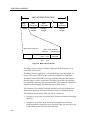
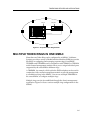
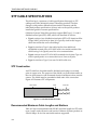
1
Cabletron Systems TOKEN RING TECHNOLOGY OVERVIEW NOTICE Cabletron Systems reserves the right to make changes in specifications and other information contained in this document without prior notice. The reader should in all cases consult Cabletron Systems to determine whether any such changes have been made. The hardware, firmware, or software described in this manual is subject to change without notice. IN NO EVENT SHALL CABLETRON SYSTEMS BE LIABLE FOR ANY INCIDENTAL, INDIRECT, SPECIAL, OR CONSEQUENTIAL DAMAGES WHATSOEVER (INCLUDING BUT NOT LIMITED TO LOST PROFITS) ARISING OUT OF OR RELATED TO THIS MANUAL OR THE INFORMATION CONTAINED IN IT, EVEN IF CABLETRON SYSTEMS HAS BEEN ADVISED OF, KNOWN, OR SHOULD HAVE KNOWN, THE POSSIBILITY OF SUCH DAMAGES. Copyright 1996 by Cabletron Systems, Inc. All rights reserved. Printed in the United States of America. Order Number: 9031941 June 1996 Cabletron Systems, Inc. P.O. Box 5005 Rochester, NH 03866-5005 Cabletron Systems, FNB, Multi Media Access Center, and TRMM are registered trademarks, and Flexible Network Bus, IRM, IRM-2, IRM-3, Media Interface Module, MicroMMAC, MIM, MMAC, MMAC-3, MMAC-3FNB, MMAC-5, MMAC-5FNB, MMAC-8, MMAC-8FNB, MMAC-M8FNB, MultiChannel, STHI, TRC-800, TP IM, TRBMIM-T, TRFOT, TRMM-2, TRMM-4, TRMMIM, TRRMIM, and TRXI are trademarks of Cabletron Systems, Inc. VT- (100, 200, et. al.) series is a trademark of the Digital Equipment Corporation. i NOTICE ii CONTENTS CHAPTER 1 INTRODUCTION USING THIS MANUAL .................................................................................................... 1-1 RECOMMENDED READING.......................................................................................... 1-1 CHAPTER 2 TOKEN RING OVERVIEW INTRODUCTION............................................................................................................. 2-1 TOKEN RING TOPOLOGY ............................................................................................. 2-2 LOCAL AREA NETWORK STANDARDS........................................................................ 2-3 Open Systems Interconnect (OSI) Model ................................................................. 2-3 Access Method ......................................................................................................... 2-6 Advantages of Token Ring ........................................................................................ 2-7 Disadvantages of Token Ring ................................................................................... 2-7 PHYSICAL LAYER .......................................................................................................... 2-8 Physical Layer Signaling Technique........................................................................ 2-10 Active Monitor ......................................................................................................... 2-11 Latency ................................................................................................................... 2-12 Signal Timing .......................................................................................................... 2-12 Accumulated Jitter .................................................................................................. 2-12 Ring Latency........................................................................................................... 2-13 TOKEN RING PROTOCOL OPERATION ..................................................................... 2-13 Station Insertion...................................................................................................... 2-14 Lobe Test.......................................................................................................... 2-14 Physical Insertion ............................................................................................. 2-14 Address Verification.......................................................................................... 2-14 Ring Poll Process ............................................................................................. 2-15 Request Initialization ........................................................................................ 2-15 The Active Monitor.................................................................................................. 2-15 The Standby Monitor .............................................................................................. 2-16 Monitor Contention Process ................................................................................... 2-16 Claim Token...................................................................................................... 2-16 Frame Transmission................................................................................................ 2-17 Access Priority ................................................................................................. 2-17 Stacking Station ............................................................................................... 2-18 Ring Management .................................................................................................. 2-18 Purging the Ring .............................................................................................. 2-18 Beaconing ........................................................................................................ 2-19 Beacon Receive (Auto Removal) ..................................................................... 2-19 SOURCE-ROUTE BRIDGING METHOD...................................................................... 2-20 Route Discovery ..................................................................................................... 2-20 Source Routing ....................................................................................................... 2-21 Bridge and Ring Numbering ................................................................................... 2-21 Control Field..................................................................................................... 2-21 iii CONTENTS TOKEN RING MANAGEMENT......................................................................................2-22 FRAME TYPES .............................................................................................................2-25 Fill Sequence ..........................................................................................................2-25 Abort Format ...........................................................................................................2-26 Token Format ..........................................................................................................2-26 Starting Delimiter (SD)......................................................................................2-27 Access Control (AC) .........................................................................................2-27 Ending Delimiter (ED) .......................................................................................2-28 Data Frame Format .................................................................................................2-28 Start of Frame and End of Frame Sequences ..................................................2-29 Destination Address (DA) .................................................................................2-30 MAC Frame Format.................................................................................................2-31 Configuration Report Server.............................................................................2-35 Ring Parameter Server .....................................................................................2-36 Ring Error Monitor ............................................................................................2-36 CHAPTER 3 TOKEN RING DEVICES AND APPLICATIONS TOKEN RING DEVICES..................................................................................................3-1 Multi-Media Access Centers (MMACs) .....................................................................3-1 Concentrators............................................................................................................3-2 Ring In/Ring Out (RI/RO) Devices.............................................................................3-2 Media Flexibility and Conversion...............................................................................3-3 Switches and Bridges ...............................................................................................3-3 Token Ring Management Modules............................................................................3-4 EXPANDING A TOKEN RING NETWORK ......................................................................3-4 MULTIPLE TOKEN RINGS IN ONE MMAC.....................................................................3-5 BRIDGED TOKEN RING NETWORKS ...........................................................................3-6 CHAPTER 4 TOKEN RING NETWORK CABLING TERMINOLOGY ..............................................................................................................4-2 STP CABLE SPECIFICATIONS ......................................................................................4-4 STP Construction ......................................................................................................4-4 Recommended Maximum Cable Lengths and Stations ............................................4-4 Cable Connectors .....................................................................................................4-6 Medium Interface Connector (MIC) ....................................................................4-6 DB9 Connector ...................................................................................................4-6 RJ45 Connector..................................................................................................4-7 UTP CABLE SPECIFICATIONS ......................................................................................4-7 UTP Construction......................................................................................................4-7 Recommended Maximum Cable Lengths and Stations ............................................4-8 Fiber Optic Cable Specifications......................................................................................4-8 Fiber Optic Construction ...........................................................................................4-9 Fiber Optic Types ......................................................................................................4-9 Recommended Maximum Cable Lengths and Stations ..........................................4-10 iv Chapter 1 INTRODUCTION Welcome to the Token Ring Network Technology Overview. It provides an introduction to Token Ring network concepts and physical components. USING THIS MANUAL Chapter 1, Introduction, provides an overview of this document and lists several reference documents related to Token Ring networks. Chapter 2, Token Ring Overview, covers basic concepts related to Token Ring network operation and design. Chapter 3, Token Ring Devices and Applications, describes select devices from the Cabletron Systems Token Ring product line and presents several network configuration examples, showing applications for these products. Chapter 4, Token Ring Network Cabling, describes media types used in Token Ring networks. RECOMMENDED READING The following publications contain information about implementing Token Ring networks. Local Area Networks, IEEE Standard 802.5 Token Ring Access Method and Physical Layer Specifications Commercial Building Wiring Standard, TIA/EIA-568A Standard 1-1 INTRODUCTION 1-2 Chapter 2 TOKEN RING OVERVIEW This chapter introduces Token Ring features and describes characteristics that distinguish Token Ring from other Local Area Network (LAN) technologies such as Ethernet and FDDI. INTRODUCTION The Token Ring network protocol is non-contention based, which means that because only one station on the network can send data at one time, stations do not have to compete for access to the transmission medium. This is controlled by token passing. The token is a unique set of bits that is recognized by each station on the ring. Only when holding the token may a station initiate data transfer. A timer (Token Holding Timer) controls the maximum time that a station can use the network before releasing the token. The token is passed from one station to another, providing each station in turn with an opportunity to transmit. A station obtains a token from its upstream neighbor, and, when finished with the token, passes it to its downstream neighbor. A station will always pass the token to the next active station physically in line on the ring. After receiving the token, a sending station sets the token to busy and sends out a data message. The data is passed from station to station around the ring, being copied by the station for which it is addressed, the destination address. After being copied by the destination station, the data circulates until it arrives back at the source station, where it is deleted. The station then releases the token onto the ring for the next station to claim. The rules of a Token Ring network are monitored by the Active Monitor (AM). The AM ensures that implementational rules of the Token Ring protocol are being followed and that the network can overcome violations. 2-1 TOKEN RING OVERVIEW TOKEN RING TOPOLOGY The Token Ring topology, or logical shape, is a ring. A ring topology is a point-to-point network in which the network devices are connected, machine to machine, in an unbroken unidirectional circle. The Token Ring topology uses an access method called token passing. No station may transmit unless that station first possesses the token. Because of this restriction on transmitting, token rings are deterministic, since it is possible to accurately calculate the transmission delay times. Ring topologies can be complex in nature. Although they are relatively easy to expand, it usually takes careful calculations of physical-design factors, maximum stations supported and the cabling structure for example, to keep the network within specification. Most ring topologies resemble a physical star, but careful examination will reveal a logical ring. In Figure 2-1, the use of a multi-station access unit (MSAU) with stations star-wired to it supports the logical ring. MSAU Logical Ring Media Path Station Station Station Station Figure 2-1. Physical Layout of a Token Ring Network Adding or removing stations on the network is relatively simple and can be done while the network is active. Software included with the Token Ring adapter cards in each station on the ring automatically reconfigures the logical ring in response to the addition or removal of stations on the ring. Special connectors are used to maintain the integrity of the ring. Spring loaded shorting bars inside the connector loop back the cable when the connector is unplugged from a jack. 2-2 TOKEN RING OVERVIEW LOCAL AREA NETWORK STANDARDS Networking standardization has one goal: to allow systems to communicate with each other. This is particularly relevant to LANs where the two primary objectives are to permit common resource sharing and to allow interconnection of many different systems to the same physical medium. To achieve this, each system must conform to the same standard for using the LAN. Proprietary network physical media and topologies would be workable if only one manufacturer existed. Standards play an important part in LAN design and implementation and interoperability between vendor products. Open Systems Interconnect (OSI) Model The International Standards Organization (ISO) OSI model is intended to serve as a common basis for development of system-connection standards by means of a consistent hierarchy of rules. The OSI model defines where needed tasks for system interconnection are performed, but not how they are done. How a task is performed in a network is defined in the protocols, or rules, written for a network type, but are based, nevertheless, on the OSI model. The tasks that are needed to manage and control the network are divided into functional groups called layers. The layers may be implemented by hardware, software, or both. Each layer in a network-based OSI model performs a specific task or group of tasks required for proper system interconnection. There are seven layers in the OSI model, as shown in Figure 2-2. A brief description of each layer follows. 7 Application 6 Presentation 5 4 3 2 1 Session Transport Network Data Link Physical Figure 2-2. OSI Model 2-3 TOKEN RING OVERVIEW Physical (Layer One) This layer interfaces directly to the physical medium and is responsible for sending and receiving a stream of bits across that medium. It defines the electrical, mechanical, and signal characteristics to the medium. Data Link (Layer Two) This layer controls the flow of information between systems and the next adjacent system on the path to the final destination. It provides simple error correction and detection mechanisms to eliminate loss of data and data corruption. It is also responsible for packaging data into frames ready for transmission over the network. Network (Layer Three) This layer provides a means of establishing a connection between systems. It enables systems to be connected together, even if they are on different subnetworks and if the subnetworks are of different types. It controls networking issues such as routing and flow control. Transport (Layer Four) This layer provides the upper layers with guaranteed quality of service in terms of throughput and reliability. This quality of service is requested by the Session Layer and is provided irrespective of the speed and reliability of the underlying communications services. For example, the Transport Layer can enhance throughput performance by multiplexing or running several network connections in parallel in order to service a single transport connection. Similarly, in order to enhance reliability, it may use error correction and detection schemes. Session (Layer Five) This layer provides a means for organized and synchronized exchange of data between systems. In simple terms, it establishes a framework for dialogue between systems. For example, when a connection is established, the Session Layer arranges the way the data should be sent: in one direction only, in alternate directions, or in both directions at the same time. Presentation (Layer Six) This layer provides a common representation of information while it is in transit between two cooperating systems. For example, because two end systems may use different character sets and different codes to represent symbols, the Presentation Layers of the two systems must agree on a common representation. Having done so, they can translate the data which is sent to them from the Application Layer into that common representation ready for transmission across the network. 2-4 TOKEN RING OVERVIEW Application (Layer Seven) This layer provides access to the OSI environment and provides communication based services to the end users. Typical of the services it provides are file-transfer services, file-directory operations, and electronic messaging. All the subordinate layers of the model exist to support, and make possible, the activities of this layer. The OSI basic reference model was designed to enable communication between heterogeneous systems using traditional wide area networking technology. The result is that LAN standards, such as those defined by the IEEE, do not readily fit into the OSI structure. This is particularly true of the Physical and Data Link Layers, where the diversity of physical media and network topologies used in LANs requires that different physical components be used and a different data link protocol be used for each type. For this reason, when applying LAN standards to the OSI Reference Model, the Physical Layer and the Data Link Layer are often divided into sublayers. The Data Link Layer has two sublayers - Media Access Control (MAC) and Logical Link Control (LLC). The MAC sublayer corresponds to a particular type of LAN, for example, CSMA/CD or Token Ring. It is responsible for receiving data from the LLC sublayer and encapsulating it into a packet ready for transmission. The MAC sublayer must also recognize and generate addresses and the generation and verification of frame-check sequences. Its primary function is the delivery of frames and to ensure that transmission onto the network is controlled. The LLC sublayer is used to provide a consistent service to the Network Layer irrespective of the MAC sublayer in use. Therefore, the upper layers need not worry about whether they are connected, for example, to a Token Ring or Ethernet network. Communications appear within a network as direct peer-to-peer communications to the user. Data appears to go from the sending application layer directly to the receiving application layer as if the devices were attached locally. In actuality, the user message is routed from the sending application layer down through the other layers of the system. Each layer adds to or modifies the message according to its protocol (e.g., adding address and error checking information). The message passes through all the layers of the system before appearing on the data channel (or communication media) at the Physical Layer. From the data channel the message passes upward through the same layers at the destination device. As the message progresses from layer to layer, each layer changes the message according to its protocol (e.g., stripping address information and performing error checking). The end result is the same message as was originally sent, arriving at the top of the destination Application Layer. 2-5 TOKEN RING OVERVIEW Access Method Communication between devices on a network requires that there be a common method for transmitting and receiving messages, and every device on the network must have the ability to talk at some point. Also, if two devices attempt to talk at the same time the data will become corrupted. Thus there are two conflicting requirements. The need to talk on the LAN and exchange information and the need to make sure only one device out of all the network devices talk at any one time. The technique used to resolve these requirements is known as Media Access Control (MAC), which controls the contention between users wishing to gain access to the medium to transmit information. It should be noted that on such a system, data transmitted from a device will be seen by all other devices, only one of which is the receiving station. It is up to the receiving device to decide what to do with the information. The Media Access Control method known as token passing is implemented on a ring topology. The Token Passing Protocol works in the following way: 1. A unique series of bits, known as a token, is recognized by each station on the network. 2. Only when holding the token is a station able to initiate data transfer. A timer (the Token Holding Timer) controls the maximum time that a station can use the network before passing the token. 3. The token is passed from one station to the next, providing each station in turn with an “invitation to transmit.” Token passing on a ring is implicit since each station on the ring accepts the token from the station on its receive, or upstream, side and then passes to the station on its transmit, or downstream, side. A station always passes it to the next active station physically in line. 4. When transmitting the sending station sets the token to busy and sends out a frame of data. The data is passed from station to station around the ring, being copied by the station with the proper destination address. 5. After being copied by the destination station, the data continues to circulate, until it arrives back to the source, where it is deleted. When transmission is complete, the token is released as a free token by the source and passed to the next station. 6. Each station regenerates and repeats the information bit by bit. 7. The physical insertion or removal of a station on the ring does temporarily interrupt the network operation, but the network automatically recovers. 2-6 TOKEN RING OVERVIEW 8. Through the use of simple time-out circuits, the ring has a means of protection against a station that fails to pass the token on. 9. An Active Monitor station ensures that these rules are being followed and can detect and recover from violations of these rules. Advantages of Token Ring The main advantages of using Token Ring are as follows: • It provides a deterministic performance specification, by which the access time (i.e., the maximum time between (n) and (n+1) use of the token) can be determined. • Under heavy loading the protocol is at its most efficient and will degrade in a controllable and predictable manner. • The physical layer provides a number of features for hardware error detection and performance tuning. • Token Ring provides for a number of station-management (SMT) agents to allow network management products to monitor the performance and collect error and other reporting statistics. • Supports large frame sizes up to 18 kilobytes at 16 Mbps. Disadvantages of Token Ring The main disadvantages of using Token Ring are as follows: • The complexity of the protocol requires an understanding of its operation to allow for network management. • The number of nodes is relatively low (260 per ring segment) compared to Ethernet (1024). 2-7 TOKEN RING OVERVIEW PHYSICAL LAYER The Token Ring topology is characterized as a logically circular, unidirectional transmission path without defined ends. The physical topology is a star wired system with each station having its own cable running back to a central point. Although wired as a star, tracing of the cable run will reveal a continuous ring. The ring is most typically constituted by sets of MSAUs interconnected via their Ring In/Ring Out (RI/RO) ports. Each MSAU typically has eight to twenty-four Trunk Coupling Units (TCU), or lobe ports, into which stations are connected via lobe cabling. In practice lobe cabling can consist of various cable segments constituting the lobe-to-TCU connections. Segments typically include patch cables from the TCUs to the main wiring panel, the lengths of the main wiring to the station locations, and then patch cables from floor/desk sockets to the stations. Token Ring has many definitions that pertain only to this topology, the following definitions are to clarify what is meant throughout this document. Multi-Station Access Unit (MSAU) An MSAU is a device that provides a centralized group of TCUs, each of which offers station connection to the ring trunk. The MSAU is typically called a concentrator or hub. MSAU can be active or passive and intelligent or non-intelligent. If several MSAUs form a ring trunk, they must be connected together through their Ring In/Out Ports. The MSAU should not be confused with the Medium Attachment Unit (MAU), a term that refers to media transceiver devices. Trunk Coupling Unit (TCU) The TCU is the physical device that couples the station lobe cable to the trunk cable. The TCU provides the means to insert the station into the ring or bypass it when the station is inactive or the lobe cable has failed. Trunk Cable The Trunk Cable is the cable that runs within and between MSAUs. It can consist of either fiber optic or shielded or unshielded twisted-pair copper cable. Twisted-pair copper cable uses two positive transmit wires in normal mode, with no crossover, while fiber has one transmit fiber and one receive fiber. The positive transmit circuit of the Ring Out port of an MSAU connects to the positive receive circuit of the Ring In port on the downstream MSAU. Thus, in normal mode, the second pair of wires is not used and is known as the backup, or secondary, ring path. The backup path is used to re-route the ring path at a port that is wrapped. 2-8 TOKEN RING OVERVIEW Lobe Cable The lobe cable is used to attach a station the TCU on an MSAU. In practice lobe cabling can consist of various cable segments constituting the lobe-to-TCU connections. Segments typically include patch cables from the TCUs to the main wiring panel, the lengths of the main wiring to the station locations, and then patch cables from floor/desk sockets to the stations. Like trunk cable, lobe cabling can consist of either fiber optic or unshielded or shielded twisted pair copper cable. Lobe cabling is straightthrough with no crossover. Repeater Circuitry Repeater circuitry is typically embedded in many concentrator products, including Media Interface Modules and stackable hubs. It re-times and regenerates the frame to drive longer distances between stations. Note also that each station provides the repeater function. Converters A repeater that also converts from one media type to another, that is fiber signals to copper or vice versa. Wiring Closet The distribution point for the building wiring, typically consisting of a number of patch panels. This is the obvious location to place the MSAUs. Ring In and Ring Out (RI/RO) Ports RI/RO ports are the connectors on the MSAUs used to interconnect the units via trunk cabling. The wrap feature is implemented at these interfaces. Ring Insertion For a station to become an active member of the ring it must insert itself into that ring. It does this by sending a low voltage DC signal to the MSAU. This signal does not effect the data signal on the lobe cable. For this reason it is usually referred to as the Phantom Current. When the phantom drive is received by the MSAU, a relay closes, enabling the station to insert into the ring. The phantom drive will not be sent if the station’s hardware adapter has not been initialized by the software. 2-9 TOKEN RING OVERVIEW Ring De-Insertion If the station’s hardware adapter experiences a non-recoverable error, the phantom current will drop causing the relay on the MSAU to open. This breaks the circuit for that lobe and the station is then bypassed from the ring. Typical causes for this condition are the station being powered off, the lobe cable being unplugged, or an adapter hardware failure. While stations are inserted or removed from the ring, there is a temporary break in the ring circuit while the relay opens or closes. The Token Ring protocol allows for recovery from this situation with virtually no impact on communications among stations still inserted into the ring. Phantom Current A DC voltage applied by a station trying to insert into the ring. The current opens the bypass relay in the TCU allowing the station access. The voltage is transparent to the signal, hence its name. If a cable failure causes phantom current to drop, the relay will close thus bypassing the faulty lobe, offering protection to the whole ring against one faulty cable. Adjusted Ring Length (ARL) When a segment of trunk cable fails, the wrap feature connects the main path to the backup path. This creates a new data path, one that is longer than the original. The worst case, or longest path, would be brought about by the failure of the shortest trunk cable segment. This worst case is known as the ARL and is an important factor calculated into the network installation composed of passive devices with no repeater functionality. Physical Layer Signaling Technique The technique defined by the IEEE for Token Ring signaling is known as Differential Manchester Encoding on a baseband transmission. Differential Manchester Encoding uses a signal transition at the start and center of the bit cell time to represent a 1, 0, J, or K bit, as shown in Figure 2-3. The bit cell times for 4 Mbps Token Rings is 250 ns and 62.5 ns for 16 Mbps rings. In the case of the two data symbols, binary 1s and 0s, a signal element of one polarity is transmitted for one half of the bit cell time followed by the transmission of a signal element of the opposite polarity for the remainder of the bit cell time. This provides two distinct advantages: 2-10 • The resulting signal has no DC component and can readily be inductively or capacitively coupled. • The forced mid-bit transition conveys inherent timing information on the channel. TOKEN RING OVERVIEW With Differential Manchester Encoding the sequence of signal polarities is completely dependent on the polarity of the second half of the previous bit cell time. If a bit to be transmitted during any given bit cell time is a 0 (zero), then the polarity of the first half of that bit cell time is opposite to that of the previous bit cell time, consequently as polarity changes occur at the start of the bit cell time as well as the forced mid-bit time. If the bit to be transmitted is a 1 (one), the polarity of the first half of that bit cell time is the same as that of the previous bit cell time and as such there is no polarity change at the start of the bit cell time. 1 0 1 1 0 0 One Bit Cell Time Bit = 0 if there are two polarity changes in a bit cell time Bit = 1 if there is one polarity change in a bit cell time 1 J 0 0 K Bit = J if there is no polarity change at start of bit time Bit = K if there is a polarity change at start of bit time Figure 2-3. Token Ring Manchester Differential Encoding Active Monitor Each ring must have a master station known as the Active Monitor (AM). This station plays a critical role in both the MAC/Data Link layer and the Physical layer functions. All stations have the ability to be the Active Monitor but only one Active Monitor is allowed per ring at any one time. All other stations become Standby Monitors. The AM is usually selected at initialization time and is usually the first station to access the ring. However, there are situations when a new AM is required, for example, 2-11 TOKEN RING OVERVIEW when the AM loses power. The process to select a new AM is known as Monitor Contention. The process to select the new AM begins with one of several timers expiring indicating that either the current AM has failed or that some other network parameter has not been corrected by the current AM. The Monitor Contention process can be started by any station on the ring and begins as timers expire. As stations time out they immediately begin broadcasting Claim Token frames. Stations receiving Claim Tokens will compare the source address of the frame with their own address. Stations with an address value less than the source address of the Claim Token will repeat the received frame onto the ring and cease sending their own Claim Token. If its own address is greater, it will then generate its own Claim Token frame and delete the received token. Eventually, the station with the highest address will receive its own Claim Token frame back, allowing it to reissue three successive Claim Token frames to ensure the integrity of the network. After receiving three consecutive Claim Tokens that station then becomes the AM. Latency So that a token can circle the ring, the IEEE 802.5 standard specifies that the ring must be big enough to accommodate a single token. The token is a unique 24 bit pattern. The token bandwidth depends on the speed at which it is being clocked, 4 or 16 Mbps. Thus the unit of time used to measure the token transmission is the unit of a bit time, 250 ns or 62.5 ns. It is impractical to physically build cabling on each end of every Token Ring network to accommodate this token transmission time. Thus, the Active Monitor is responsible for providing a latency buffer of a minimum 24 bit times. This is described as the Assured Minimum Latency Buffer. Signal Timing As well as providing the token latency, the Active Monitor is responsible for providing the master source timing for transmitted data using internal clocking. As the data passes from the Active Monitor to the next downstream station, the receiving station phase locks on the clock of the received data and derives its transmit clock. Accumulated Jitter Due to variations in cable impedance and the accuracy of the locking clock circuits, very small variations in speed may result. In worst-case scenarios each station may add to the problem. The result is that the Active Monitor receive clock could lock in at a data rate significantly faster or slower than 2-12 TOKEN RING OVERVIEW its transmit clock. This problem is known as Accumulated Jitter and is one of the main reasons for the limitations on the number of stations and repeaters on a ring. To overcome Accumulated Jitter an elastic buffer is set up by the Active Monitor, in addition to the Latency buffer. For a 4 Mbps ring the buffer is initiated at 3 bits and can grow to 6 bits or shrink to 0 bits. For 16 Mbps, the buffer is initialized at 16 bits and can grow to 32 bits or shrink to 0 bits. Ring Latency Each station uses a one bit buffer in which to store the incoming signal. As the next bit comes in the buffer releases the bit to the ring effectively regenerating and re-timing the signal. Therefore each station induces at least a one bit latency. As each bit passes through a stations repeater buffer, a copy may also be made in the stations frame buffer, so gradually the frame is built up bit by bit. Depending on the information already stored in the frame buffer, a station may be allowed to modify the current bit in its repeater buffer. This function will be described in detail later. TOKEN RING PROTOCOL OPERATION While looking at the protocol operation it is important to understand that the IEEE 802.5 standard provides that each station has the following four (4) Network Management Agents: • • • • Active or Standby Monitors (AM or SM) Ring Error Monitor (REM) Configuration Report Server (CRS) Ring Parameter Server (RPS) These agents are responsible for generating the 25 variations (plus an additional 17 if an IBM application) of MAC frames used for ring operation. Inherently this provides for a wealth of network statistics that are used by network management products. The main functions of the Token Ring Protocol are illustrated, during ring operation, when looking at how a new station is inserted into a ring. The following sections describe how a station becomes part of the ring and how fault diagnosis and recovery provide the ring with a resilient network. 2-13 TOKEN RING OVERVIEW Station Insertion The act of powering up a station does not immediately enable it to become part of the ring. Certain tests are performed while the adapter is being initialized by the software drivers. The basic tests are known as insertion tests. These tests are made whenever an attempt is made to open the Token Ring adapter. Lobe Test The Lobe Test involves the station sending a string of Lobe Media MAC frames on that station’s lobe. This test ensures there are no faults on the lobe. Physical Insertion If the Lobe Test is successful, the station activates its phantom drive and inserts into the ring. The time allowed to insert into the ring is 5 ms, which is the maximum time a ring may be broken. The phantom current is two separate DC circuits that enable the station to detect open or short circuits in either the receive or transmit pairs. During the Physical Insertion test, the station also learns the ring’s operating speed and it determines whether an AM exists on the ring. It does this by first starting a timing process, called the Timer Standby Monitor (TSM), which specifies the time allotted the station to detect Active Monitor Present (AMP), Standby Monitor Present (SMP), or Purge Ring (PRG) MAC frames on the ring. The presence of any of these frames indicates a another station is or has been designated as the AM. If not detected within seven (7) seconds, the station transmits Claim Token frames to contend for designation as the AM. Address Verification After determining the presence of an AM on the ring, the station checks for a duplicate address on the ring using the Duplicate Address Test (DAT) frame. The station sends the frame addressed to itself out onto the ring. If the frame returns with its address recognized bits set by another station on the ring with the same address, the transmitting station will then remove itself from the ring. 2-14 TOKEN RING OVERVIEW Ring Poll Process If there is no duplicate address on the ring, the station participates in neighbor notification by learning its Nearest Active Upstream Neighbor (NAUN) and identifying itself to its nearest active downstream neighbor. The AM initiates process by sending out a broadcast AMP frame to its downstream neighbor. The downstream neighbor sets the address recognized and frame copied bits, stores the AM address, and generates a broadcast SMP frame to its downstream neighbor. The process is iterative and continual. This ensures that the MAC addresses of stations inserting into the ring are revealed to and recorded by other stations on the ring. Request Initialization The final test performed in the Station Insertion process involves a request by the new station on the ring for ring parameter values. These values typically include timer values and the ring number. The new station requests this information by transmitting a Request Parameters MAC frame to a Parameter Server on the ring, typically available from a bridge on the ring. If no server is available, then the station operates in accordance with its own defaults. The station is now a legal member of the ring and can start transmission. However, to verify that the ring is valid, it checks for the presence of an AM on the ring. The Active Monitor The first station to initialize onto the ring is the Active Monitor (AM). As part of its duties, the AM initializes the ring (Ring Purge) and issues a token. The AM supplies the master clock for the network, and all other stations receive their timing from this clock. A ring latency of 24 or 32 bits (for 4 Mbps or 16 Mbps rings, respectively) is provided by the AM. The Monitor bit is set and checked by the AM to ensure that tokens and frames do not recirculate the ring. 2-15 TOKEN RING OVERVIEW The Standby Monitor All other stations are Standby Monitors (SMs). The SMs verify that the AM is on the ring and performing its duties. Each SM checks for good tokens using the “Good Token Timer” (2.6s); the SMs also verify that the AM is transmitting an Active Monitor Present MAC frame using the Receive Poll Timer (15s). If an SMs’ Good Token Timer or Receive Poll Timer expires, the station issues a Claim Token MAC frame. In the event there is a Claim Token MAC frame issued, all stations enter into a monitor contention dialogue, resulting in one station (the highest currently active address) establishing itself as the AM. Monitor Contention Process All stations are capable of being AM but a ring must only have one. All other stations go into SM mode. The establishment of the AM is usually achieved at initialization time. It is usually the first station to access the ring. However, there are obviously situations when a new active monitor is required. This process of selecting a new AM is known as Monitor Contention and can be started if any of the following conditions occur: • • • • • • Good token not received every 2.6 seconds AMP (Active Monitor Present) frame not received every 15 seconds No AMP, SMP (Standby Monitor Present), or purge for 18 seconds during insertion AM cannot successfully purge the ring Clock frequency moves out of specification Beacon transmitter receives Beacon with MC Monitor contention uses a process known as Claim Token to determine which station is going to be the AM. Claim Token The Claim Token process is the same regardless of the condition that caused it. As timers expire each station starts to transmit a Claim Token MAC frame onto the ring. Thus, each station also receives Claim Token frames and compares the source address in the frame to its own. A station whose address is numerically less than the source of the Claim Token frame repeats the frame and ceases issuing its own. If its address is numerically greater, it generates its own Claim Token MAC frame and does not repeat the frame it received. 2-16 TOKEN RING OVERVIEW Therefore, the station with the highest address eventually receives its own Claim Token MAC frame back, allowing it to reissue a sufficient number (3) of successive Claim Token MAC frames to ensure the integrity of the ring. It then becomes the new AM. To ensure that all stations receive information about the AM status, an AMP MAC frame is transmitted by the AM on a periodic basis. When this timer expires in 7 seconds, an AMP frame is released by the AM. If stations do not receive an AMP frame for 18 seconds then Monitor Contention is entered. The AMP frame also allows stations to receive the address of their nearest active upstream neighbor. Frame Transmission After the station has access to the network, it can now proceed with frame transmission, as long as those frames are of sufficient Access priority. Access Priority The basic Token Ring protocol allows for the use of different access priorities. The priorities allow for a station that requires immediate transmission to receive the next available token. Priority is determined by looking at the next frame, or to be more precise, the Protocol Data Unit (PDU), queued by a station for transmission. Priority is from 000 lowest to 111 highest. The left bit is the most significant so 110 has a higher priority than 011. The following sequence of events depicts the priority system: • Station A is transmitting to Station C, and the present priority is set to 0, lowest priority. • Station B wants to transmit when the token becomes free, so as the frame is regenerated by Station B, it changes the Priority reservation field in the frame to 1. No other data is changed within the field. • Station C receives the frame and copies the data. Station C sets the frame copied bit as normal and regenerates the frame back onto the ring. • Station D also wants to transmit and has authority to send a higher priority than Station B. It therefore sets the priority reservation field to 3, overriding the priority set by Station B. Station D then regenerates the frame back onto the ring. • When Station A receives the frame it regenerates a new token with a priority of 3 and sets the reservation field back to 0. 2-17 TOKEN RING OVERVIEW • Station B still has a frame to transmit but it cannot capture the present token, which is set to priority 3; it only has a priority 1. As the token passes through Station B it sets the Priority reservation field to 1 again. Stacking Station Station D captures the token and transmits its frame. Station D has raised the service priority of the ring to 3, and is termed the Stacking Station. It notes in its reservation register that R was set to 1. It uses this to lower the ring priority later. A Stacking Station is said to be in a Priority Hold State. Station D transmits its priority frames and when finished, generates a token with priority and reservation set to that held in its register, in this example, 1. Station B captures the token and transmits its frame. Note that the Stacking Station is the only one that can lower the ring priority. Thus, when Station B has finished its transmission, it generates a new token at a higher priority of 1. Station D captures the token again and, seeing no other higher reservation set generates a new token at a 0 priority. The ring is now back to normal operation. Note that PDUs are assigned priorities according to application. Ring Management One station on each ring is designated the Active Monitor (AM). This station is responsible for monitoring the token and providing other ring management functions. All other ring stations are Standby Monitors that are capable of becoming the AM if the need arises. The AM protects the ring against error situations such as lost tokens, frames, and priority tokens that circle the ring more than once. It also provides the master clock for the ring and the 24-bit latency delay to ensure correct physical operation of the ring. Purging the Ring The AM can generate a Purge Ring MAC frame (PRG) to clear the ring of any errors. Ring purges occur in response to the following conditions: 2-18 • A station has just become AM. • A frame has circled more than once, indicated by monitor bit set to 1. • The ring is quiet or with illegal traffic, so that the Timer Valid Transmission (TVX) has expired. TOKEN RING OVERVIEW Each station on the ring, as it receives the PRG frame, cancels all timers and resets to normal repeat mode, if the frame cannot be copied. If the frame can be copied, action is taken according to the information field of the MAC frame. The information field contains the address of the Nearest Active Upstream Neighbor (NAUN). If the PRG frame successfully makes it around the ring, the monitor has been properly reset on the ring. A new token would then be issued by the monitor. It is possible that the PRG frame may not make it around the ring, in which case the monitor’s ring purge timer will expire and the monitor will enter Monitor Contention Mode (MCM). Beaconing Beaconing is initiated when a station on the ring has detected a ring failure. A beacon frame is transmitted by the station to notify the other stations on the ring of the failure. From the NAUN process each station knows where it is in ring and the beaconing process helps to identify the failure domain, which consists of the station that first spots the failure (beaconing station) and its NAUN and the ring cable between them. Beacon Receive (Auto Removal) The automatic recovery process starts when a station loses signal. Either its receiver side is faulty, or the transmitter of its NAUN is faulty. The station enters the beaconing transmit state and sends a Beacon MAC (BCN) frame around the ring. The BCN frame is read by all stations and contains the address of the sending station’s NAUN. When the NAUN sees its address it performs a self test. If the test fails, the station remains off the ring. Otherwise, it reinserts onto the ring. After transmitting the BCN the beaconing station runs a Timer Beaconing Transmit (TBT) which has a default of 16 seconds. If the beaconing station receives its BCN within this timer period, then the ring is good and the station moves to Claim Token state. If the BCN is not received before the expiration of the TBT, the Beaconing station removes itself from the ring and performs a self test. The Beaconing sequence provides a method by which the NAUN checks itself and its associated lobe wiring, and if this passes satisfactorily, the expired TBT of the Beaconing Station causes it to check itself and its associated lobe wiring. At the end of the sequence both stations and the cabling have been checked and either station, if detecting a failure, remains off-line. 2-19 TOKEN RING OVERVIEW SOURCE-ROUTE BRIDGING METHOD Source-route bridging is the predominant method used for linking Token Ring LANs. Source-route bridging is a process whereby the source device, or the sending station, rather than the bridge determines the route to other stations used for sending messages. Bridging is implemented in the Token Ring LAN environment typically for the following reasons: • To link Token Rings running at different ring speeds • To create more than one ring as the number of stations exceeds the IEEE 802.5 maximum for a single ring Route Discovery Source stations discover the routes to destination stations by sending a source-route broadcast frame, single-route or all-routes, to the destination station. If the source-route frame determines that the destination is not on the local ring, the source-route frame is sent through bridges to other rings until it arrives at the destination station. Along the route to the destination station, bridges write ring numbers, bridge numbers, and, in some cases, the maximum frame size the bridge can process to the Routing Information Field (RIF) of the source-route broadcast frame. Moreover, a bit called the Routing Information Indicator (RII) bit in the source-route broadcast frame’s source address field is set from zero (0) to one (1) to indicate that the source-route broadcast frame contains routing information in its RIF field. Upon receiving the source-route broadcast frame, the destination station reverses the direction bit in the routing control field, an entity included in the RIF, and transmits the source-route broadcast frame to the source station along the route specified in the RIF. The source station then appends data intended for the destination station to the source-route broadcast frame, transforming it into a Specifically Routed Frame (SRF). The RIF in the SRF indicates the exact route all further communications between the source station and the destination must traverse. If the internetwork configuration changes, that is for example, if a bridge along the route is removed, then the discovery process must be repeated to re-establish a new route between the source and destination stations. 2-20 TOKEN RING OVERVIEW Source Routing Upon receiving an SRF, a bridge looks for the following information in the RIF: • The ring number of the receiving port on the bridge • The bridge number • The ring number of the port on the bridge through which the bridge forwards the SRF If the bridge finds the above information, it transmits the SRF to the next ring. However, a bridge discards the SRF if any of the following situations exist: • The bridge does not find the above information. • The bridge finds the information, but the RIF length field is zero (0) or four (4) or an odd number. The length of the RIF is determined in part by the cumulative value of the Route Designators (RDs) added to the RIF by each bridge traversed during the route-discovery process. • There are multiple combinations of the above information in the RIF field, indicating a possible loop in the internetwork configuration. Bridge and Ring Numbering Each ring is allocated a unique number, using a 12-bit pattern that is determined by the bridges. Likewise, each bridge uses a 4-bit pattern to create a unique bridge identity. With a Routing field of 18 bytes, 2 bytes reserved for a control field, the RIF can hold information about 8 rings connected by 7 bridges in a series. Control Field The Control Field consists of 5 distinct sections, as follows: • • • • • Broadcast - 3 bits - indicates whether there is broadcast Routing Information or not Length - 5 bits - indicates length of Routing Information field Direction - 1 bit - indicates order of scan of RI field Largest Frame - 4 bits - indicates largest frame that a bridge will forward Reserved - 3 bits 2-21 TOKEN RING OVERVIEW TOKEN RING MANAGEMENT According to the IEEE 802.5 standards, each ring station or Network Interface Card (NIC) has the ability to perform the following network management functions: • Monitor soft and hard errors • Maintain details of the configuration, such as the Nearest Active Upstream Neighbor (NAUN) • Control various parameters such as the token priority, ring number, etc. The above functions are the normal features installed by each manufacturer. In each NIC there is a network management “Agent” that communicates with the network management “product.” The “product” has four (4) different functions: • Supervises network operation with its Active Monitor (AM) and Standby Monitors (SM). • Collects error reports by way of its Ring Error Monitor (REM), from the NICs and AM and SMs. • Signals a particular station to remove itself from the ring, through its Configuration Report Server (CRS), which also holds the current network configuration, and regulates the individual NIC parameters such as its access priority. • At the time of insertion into the ring the “product” assigns the operational parameters to the station via the Ring Parameter Server (RPS). The “agent” communicates with the product through a series of 25 AMC frames. The MAC frame is built and transmitted to one of several functional addresses in the product. There are four (4) functional addresses in the product: • • • • The Active Monitor - C00000000001H Ring Parameter Server - C00000000002H Ring Error Monitor - C00000000008H Configuration Report Server - C00000000010H Since the above entities have unique addresses, any information sent to one of the addresses can be seized for subsequent analysis. Should there be a fault on the network, the administrator can recapture the data at any one of these addresses and isolate the problem with the help of analysis tools. As mentioned previously, ring management depends on the 25 MAC frames. The following paragraphs provide a brief description of each MAC frame. 2-22 TOKEN RING OVERVIEW Claim Token Process (CL_TK) All stations are capable of being the AM, while others remain as SMs. The establishment of an AM is achieved by a Ring Station (RS) detecting the absence of an AM and originates a Claim Token, also known as Monitor Contention. The conditions on which a Claim Token MAC frame are issued are when either the standby monitors Good Token Timer or Receiver Poll timers have expired. Duplicate Address Test (DAT) Upon initialization of a workstation a DAT frame is transmitted by that station. The physical address of the station is placed in the DA field, if any other station on the network has the same address it sets the Address Recognized bit. When this occurs the network management station is informed and that station is denied access to the ring. Active Monitor Present (AMP) The Active Monitor (AM) transmits this frame to notify all other stations that an AM is present on the ring. If the AMP frame is not received by the SMs within seven (7) seconds or after a Ring Purge, the Claim Token frame is issued by the SM. Standby Monitor Present (SMP) Standby Monitors (SM) respond to AMP or other SMP frames during the Neighbor Notification process. Beacon (BCN) Any station transmits a BCN when a wire fault is detected, signal has been lost, or a station is streaming. The BCN notifies the station’s NAUN to test its receiver, transmitter, and lobe cabling. Ring Purge (PRG) The AM transmits this frame after the Claim Token MAC frame or when there has been a frame received with the M bit still set. Change Parameters (CHG_PARM) Utilized by the CRS to set ring operational values. Initialize Ring Station (INIT) The RPS transmits this frame in response to a Request Initialization MAC frame received by a station. This frame provides the correct operational parameters to the station. Lobe Media Test (TEST) This frame is used by the individual during the Ring Initialization process. It tests the continuity and bit error rate of the station lobe cabling. 2-23 TOKEN RING OVERVIEW Remove Ring Station (REMOVE) The CRS transmits this frame to a certain station when unconditional removal of that station is required. Report Error (ERROR) Any station transmits this frame to the REM when a timer expires. Report Active Monitor Error (ACTIVE-ERROR) When a Purge or AMP is received by the AM that it did not transmit, or when a Claim Token is received the AM transmits this frame to the REM. Report Neighbor Notification Incomplete (NN-INCMP) Transmitted to the REM, this frame indicates that a station has not received from its upstream neighbor during the Neighbor Notification process. Report New Active Monitor (NEW-MON) When a station has become the AM it transmits this frame to the CRS to notify it of a new AM. Report Ring Station Addresses (RPT-ADDR) This frame is a response to a Request Ring Station Attachment MAC frame. Report Ring Station State (RPT-STATE) This frame is a response to a Request Ring Station State MAC frame. Report SUA Changes (SUA_CNG) When an upstream neighbor address change is made as a result of the Neighbor Notification process, this frame is sent to the CRS. Request Initialization (RQ_INIT) This frame is transmitted by the station to the RPS, after a successful Ring Insertion process, indicating that a station has entered the ring and is ready to accept parameters from the RPS or the CRS. Request Ring Station Address (RQ-ADDR) This frame is transmitted by any of the management servers to a station. It is a request for addresses recognized by that station. Request Ring Attachments (RQ-ATTCH) This frame is transmitted by any of the management servers to a station. It is a request for information of the state of that station. 2-24 TOKEN RING OVERVIEW Request Ring Station State (RQ_STATE) This frame is transmitted by any of the management servers to a station. It is a request for information of the state of the station. Response (RSP) This frame is transmitted by any station to acknowledge receiving, or to report errors in a MAC frame. FRAME TYPES Bit sequences are transmitted onto the ring in clearly defined groups known as frames. Most frames carry fields of information that are common to all frame types. The frame types are as follows: • • • • • • Fill Sequence Abort Delimiter Token LLC data frame SMT data frame MAC management frame Fill Sequence The following defines the Fill Sequence: • Generated by the transmitting station before and after frames, tokens, or aborts. • Not frames by starting or ending fields. • Any combination of ones and zeros to expiration of the Token Holding Timer. • Avoids quiet line, which is defined as an open ring, during normal operation. 2-25 TOKEN RING OVERVIEW Abort Format This frame sequence shown in Figure 2-4 is used by a station to terminate its transmission prematurely. The Starting Delimiter (SD) and Ending Delimiter (ED) formats are the same as used for token and data frames. The sequence can be detected by any station at any stage in a frame transmission even if it does not occur in octet boundaries. SD - Starting Delimiter (one octet) ED - Ending Delimiter (one octet) (Both common to all frames) SD ED J K 1 J K 1 I E J K 0 J K 0 0 0 J K 0 1 I-0 1 E-0 1 = = = = last/only frame first/intermediate no error detected error detected at specific station = non-data J = non-data K = zero bit = one bit Figure 2-4. Abort Frame Structure Token Format A token format is the means by which the right to transmit a frame onto the ring (as opposed to repeating) is passed from one station to another. It is made up of three (3) fields: • • • Starting Delimiter (SD) - 8 bits Access Control (AC) - 8 bits Ending Delimiter (ED) - 8 bits The total number of bits in a token is 24. 2-26 TOKEN RING OVERVIEW Starting Delimiter (SD) The SD is always the same pattern of 8 bits - J K 0 J K 0 0 0. Both J and K violate the Differential Manchester Encoding scheme since they have no mid-bit polarity transition. J has the same polarity as the previous bit and K has the opposite polarity of the preceding bit. Access Control (AC) The AC field shown in Figure 2-5 has the following format: PPP | T | M | RRR Where PPP are the priority bits. These indicate the priority of the token and therefore which stations are allowed to use it. The bits are set by the issuing station and cannot be modified by other stations. There are eight levels of priority, 000 to 111. Where T is the token bit indicating whether the field is part of a free token frame or a busy token frame. This bit is set by the issuing station to a ‘0’ in a free token and a ‘1’ in a busy token with data contained in the frame. Where, RRR are the priority reservation bits. These bits are used to allow stations with high priority data awaiting transmission to request that the next token be issued at the required priority. These bits can be modified as they pass through the station’s repeater buffer. There are eight (8) levels of binary priority reservation from 000 to 111. SD AC ED SD - Starting Delimiter (one octet) AC - Access Control (one octet) ED - Ending Delimiter (one octet) P P P TM RRR P T M R - Priority Bits - 000 through 111 Token Bit - 0 defines token as free (not busy) Monitor Bit - 1 if circulated past the AM Request Priority Bit - 000 through 111 Figure 2-5. Access Control Field Format in Token Frame Structure 2-27 TOKEN RING OVERVIEW Ending Delimiter (ED) The ED has the following format: JK1JK1|I|E The first 6 bits, J K 1 J K 1, are always the same. Note that the J and K bits are non-data symbols and violate the Differential Manchester Encoding scheme. I is the Intermediate Frame bit which notes if the frame is part of a multiple frame transmission. If this bit is set to 0 then the frame is the last or only frame in the transmission sequence. If set to ‘1’ then it is the first of several or an intermediate frame. E is the Error Detected bit which is set to ‘0’ by the sending station. If any station, while regenerating the frame, detects an error, it changes this bit to a ‘1’. Note that this field is after the FCS calculation, hence the station has time to perform the FCS task and modify this bit if necessary. The station that sets the error bit will log the error by type. Data Frame Format The minimum length of a Token Ring frame is 21 octets. The maximum frame size is 18,000 bytes for 16 Mbps and 4500 bytes for 4 Mbps networks. Also the time required to transmit a frame must be no greater than the token holding period that has been established for the station, default is 10 ms. A frame is made up of the following fields: • • • • • • • • • • Starting Delimiter (SD) Access Control (AC) Frame Control (FC) Destination Address (DA) Source Address (SA) Optional Routing Info (RIF) Information (Info) Frame Check Sequence (FCS) Ending Delimiter (ED) Frame Status (FS) 8 bits 8 bits 8 bits 8 bits 48 bits 48 bits 0 or more bits 0 or more bits 32 bits 8 bits This format shown in Figure 2-6 is used to transmit both MAC and LLC messages to the destination station(s). MAC frames are covered in a later section. 2-28 TOKEN RING OVERVIEW SD AC FC DA SA INFO FCS ED FS FCSC SFS EFS SFS = Start of Frame Sequence FCSC = Frame Check Sequence Coverage EFS = End of Frame Sequence Figure 2-6. Data Frame Structure Start of Frame and End of Frame Sequences The SD and AC fields are referred to as Start of Frame Sequence (SFS), and the ED and FS fields as the End of Frame Sequence (EFS). Frame Control (FC) The Frame Control field shown in Figure 2-7 defines the type of frame and certain MAC and information frame functions. The eight bits are referenced as follows: FF|ZZZZZZ Where: FF = 00 - MAC frame (Contains MAC PDU) = 01 - LLC frame (Contains an LLC PDU) = 1x - Undefined (Reserved for future use) If the frame type is an LLC frame then the ZZZZZZ control bits are designated as rrrYYY where rrr is reserved for future use and is transmitted as 000 and the YYY bits may be used to carry the priority of the Protocol Data Unit (PDU) from the source LLC to the destination LLC entity. 2-29 TOKEN RING OVERVIEW SD AC FC DA SA INFO FCS ED FS Note that ‘r’ bits are reserved. FF ZZZZZZ FF = Frame Bits 1x = reserved 01 = Data Frame 00 = MAC Frame with vector identifier ZZZZZZ = Control Bits Undefined rrrYYY = PDU priority rrrYYY = control value for each of 25 MAC frames and 17 extended IBM MAC frames Figure 2-7. Frame Control Field Format Destination Address (DA) The DA field shown in Figure 2-8 contains the address of the station or stations for which that frame is intended. The DA field is further subdivided as follows: Bit 1 Individual or group address. If this bit is set to a ‘1’ then it is a group address. If a ‘0’ then it is an individual address. Bit 2 Universally or locally administered address. If this bit is set to a ‘1’ then the address is locally administered. If it is set to ‘0’ then it is a universally administered address. This is only true for 6-byte addressing as 2-byte addressing can only be locally administered. Bits 3 to 48 Ring/Station or Group Node Addresses. Within this 46-bit field there may be a specific ring and station address or a Group Node Address with control information known as functional addressing. These addresses represent special functions that exist in a LAN environment, i.e., Active Monitor. Functional addresses are associated with ring management functions. A Broadcast DA is a group address consisting of 16 or 48 ‘1s’ (2 or 6 octet addresses) that constitute a broadcast address. 2-30 TOKEN RING OVERVIEW SD AC FC DA SA INFO FCS ED FS I/G U/L Ring# Station Address I/G bit = 0 - Individual station address I/G bit = 1 - Group node address U/L bit = 0 - Universal addressing, 46 bits in each station’s MAC PROM. ISO/IEEE administered U/L bit = 1 - Local addressing, may be 46 or 15 bits All Broadcast, Group, and Functional Addresses Require the Leftmost Address Bit = 1 FF FF FF FF FF FF C0 00 FF FF FF FF Broadcast to all local stations Broadcast address, MAC frames Functional Addresses Require Octet Three = 0XXXXXXX C0 00 00 00 00 01 C0 00 00 00 00 02 C0 00 00 00 00 08 C0 00 00 00 00 10 C0 00 00 00 01 00 Active Monitor Ring Parameter Server Ring Error Monitor Configuration Report/Server/Net Mgr. Bridge Group Addresses Require Octet Three = 1XXXXXXX YY YY ZZ ZZ ZZ ZZ Group address supplied by app. Where: Y = Group Root Address Z = Specific Group Address Figure 2-8. Destination Address Field MAC Frame Format MAC frames are originated, received, and acted upon by stations. These frames control the operation of the Token Ring network and any station operations that affect the ring. The MAC frames all have the same Frame Control field format. The control bits for a MAC frame are contained in the MA Information Field (also called MAC LLID Frame), shown in Figure 2-9. 2-31 TOKEN RING OVERVIEW MAC INFORMATION FIELD MAC LLID MAC Subvector 4 bytes Variable Length MAC Subvector Variable Length Major Vector Length (LL) Variable Length Major Vector ID (MVID) Class Byte 2 bytes MAC Subvector Dest. Class Source Class 1/2 byte 1/2 byte Command Byte Specific Code Point 1 byte Figure 2-9. MAC LLID Field Format The Major Vector consists of a MAC length and ID (LLID) and 0, 1, or more MAC sub-vectors. The Major Vector Length (LL) is a 2-byte field that gives the length, in bytes, of this specific MAC major vector, including the LL field itself. The Major Vector ID (MVID) is a 2-byte field that identifies the function that this major vector is to perform. The Major Vector ID is divided into two subfields, Function Class and Command. The Command subfield is a single byte that uniquely identifies the type of MAC frame. The Function Class subfield is further divided into two 4-bit fields that define the destination and source function classes for the MAC frame. The destination and source fields provide two functions: 1. Provide a way to route a received MAC frame to the desired handling function. 2. Provide a way to filter MAC frames that are built and sent by an attached product, using the source class field. They also provide a way to filter MAC frames received from the ring. 2-32 TOKEN RING OVERVIEW If the frame type is a MAC frame, all stations on the ring act on the state of ZZZ control bits of the Frame Control field. There are 25 MAC frames detailed in the standard. For example, 0002 indicates a beacon frame, 0005 is an AM present frame. MAC frames are used for network operation rather than transfer of higher layer data. Table 2-1 shows the YYY Control Bit values and functions. Table 2-1. YYY Control Bit Values and Functions Major Vector ID (Hex) MAC Frame Frame Control Field (Hex) 00 Response 01 Destination Class Source Class Subvector (HEX) 00 Source class of received frame Station 09 20 Beacon 02 Station Station 01 02 0B 03 Claim Token 03 Station Station 02 0B 04 Ring Purge 04 Station Station 02 0B 05 Active Monitor Present 05 Station Station 02 0B 06 Standby Monitor Present 06 Station Station 02 0B 07 Duplicate Address Test 01 Station Station None 08 Lobe Test 00 Station Station 26 09 Transmit Forward 00 Station Config. Report Server 27 0B Remove Ring Station 01 Station Config. Report Server None 2-33 TOKEN RING OVERVIEW Table 2-1. YYY Control Bit Values and Functions (Continued) Major Vector ID (Hex) 2-34 MAC Frame Frame Control Field (Hex) Destination Class Source Class Subvector (HEX) 0C Change Parameters 00 Station Config. Report Server 03, 04, 05, 06, 07, 09 0D Initialize Ring 00 Station Ring Parameter Server 03, 04, 05, 09 0E Request Ring Station Address 00 Station Config. Report Server 09 0F Request Ring Station State 00 Station Config. Report Server 09 10 Request Ring Station Attachments 00 Station Config. Report Server 09 20 Request Initialization 00 Ring Parameter Server Station 02, 22, 23 22 Report Station Address 00 Config. Report Server Station 02, 09, 0B, 2B, 2C 23 Report Station State 00 Config. Report Server Station 09, 23, 28, 29 24 Report Station Attachments 00 Config. Report Server Station 06, 07, 09, 22, 2C 25 Report New Active Monitor 00 Config. Report Server Station 02, 0B, 22 26 Report NAUN Change 00 Config. Report Server Station 02, 0B 27 Report Neighbor Notification Incomplete 00 Ring Error Monitor Station 0A TOKEN RING OVERVIEW Table 2-1. YYY Control Bit Values and Functions (Continued) Major Vector ID (Hex) MAC Frame Frame Control Field (Hex) Destination Class Source Class Subvector (HEX) 28 Report Active Monitor Error 00 Ring Error Monitor Station 02, 0B, 30 29 Report Soft Error 00 Ring Error Monitor Station 02, 0B, 2D, 2E 2A Report Transmit Forward 00 Config. Report Server Station 2A Configuration Report Server The Configuration Report Server is a network management function that resides on every ring in a multiple ring environment. It serves four purposes in the Token Ring network: • Collects information from the ring (Report NAUN Change and Report New Monitor MAC frames) and reports this information to the AM. This assures that information is always complete and accurate ring configuration information. • Requests status information from stations on its local ring as requested. • Sets the values of operational parameters for stations on its local ring as directed. • Changes the configuration of its local ring by requesting a station to remove itself from the ring as directed. 2-35 TOKEN RING OVERVIEW Ring Parameter Server The ring Parameter Server is a network management function that resides on every ring in which the operational parameters are centrally managed. It serves two (2) purposes for the Token Ring network: • Target for all Request Initialization MAC frames that are sent by ring stations during attachment to the ring. This allows the station to send the frame to a known address (the ring parameter server functional address) on its own ring only, without having to broadcast on all other rings. The ring parameter server sends this registration information to the AM. • Makes the following parameters readily available to all ring stations on the ring (using the Station MAC frame): - Ring Number - Station Soft Error Report Timer Value - Physical Location This guarantees that the Ring Number and Station Soft Error Report Timer Value are the same for all stations on the ring. Ring Error Monitor The Ring Error Monitor provides three functions: • Collects error reports from stations on the attached ring. • Further analyzes the soft error reports and when thresholds are exceeded, reports the fault domain and the error condition to the AM. • Forwards the other reports received from stations on the ring to the AM. This server is present on rings for which errors are to be monitored or analyzed. Its functional address is the destination address for error reports generated by stations. 2-36 Chapter 3 TOKEN RING DEVICES AND APPLICATIONS This chapter lists severalToken Ring products available from Cabletron Systems and presents examples of how Token Ring devices can be used in a Token Ring network. These examples help clarify features of the devices and applications and do not illustrate all possible applications. Contact Cabletron Systems Technical Support Department if you have questions related to your specific network applications. Cabletron offers a variety of Token Ring network products. This chapter describes applications using some of these products. Applications include the following: • Expanding a Token Ring network • Configuring multiple Token Ring networks in one MMAC • Bridging Token Ring networks TOKEN RING DEVICES This section highlights features and functions of Cabletron Systems Token Ring products and products used to implement Token Ring networks. Multi-Media Access Centers (MMACs) Cabletron Systems MMACs are modular wiring hubs with a protocol-independent Flexible Network Bus (FNB) backplane designed to support not only Token Ring connectivity and management products but also Ethernet, FDDI, and SNA-to-LLC products as well. The MMAC series is shown in Figure 3-1. 3-1 TOKEN RING DEVICES AND APPLICATIONS Management Slot MIM Slots Management Slot MIM Slots MIM Slots MMAC-M3FNB Management Slot MMAC-M5FNB MMAC-M8FNB Figure 3-1. MMACs Concentrators Modular concentrators install in the MMAC and provide multi-station access to the main Token Ring network through lobe cabling connected at Trunk Coupling Unit (TCU) ports. These devices provide multiple TCU (or lobe) ports. A TRMIM-24A, for example, is a concentrator that installs within an MMAC and provides twenty-four lobe ports that connect to the MMAC’s Flexible Network Bus (FNB). A TRXMIM-24A, for example, provides the same functionality as a TRMIM-24A, except that it allows individual ports on the same MIM to be assigned to different rings. Cabletron Systems also provides standalone concentrators, such as the TRXI series of active and passive intelligent concentrators. Other standalone concentrators, such as those included in the MicroMMAC-T series of intelligent hubs and the STH series of intelligent and non-intelligent hubs, for example, are “stackable” and allow additional concentrators to be attached and thus act as one logical concentrator. Ring In/Ring Out (RI/RO) Devices Ring In/Ring Out (RI/RO) ports provide externally accessible trunk connections. Use of these ports allow you to extend the ring by connecting to RI/RO ports on different Token Ring devices. The TRRMIM-4AT, for example, has a set of user-configurable RI/RO ports, which provide trunk port links to the MMAC in which it is installed. Connecting these RI/RO ports to RI/RO ports on another hub joins these hubs on a single ring. 3-2 TOKEN RING DEVICES AND APPLICATIONS Media Flexibility and Conversion Token Ring networks can be wired with different types of media. Cabletron Systems series of Token Ring Port Interface Modules (TPIMs), shown and listed in Figure 3-2, provide a method to interchange port interfaces supporting different media types for devices that support TPIM installation. TPIM-F2/F3 TPIM-T2/T4 TPIM-T1 Figure 3-2. TPIMs TPIM specifications are listed in Table 3-1. Conversion products such as the TRFOT-2, a twisted pair-to-fiber optic converter, enable you to connect cabling of certain media types to a device supporting another media type. Table 3-1. TPIMs and Media Types TPIM Media Type Connector Type TPIM-T1 Shielded Twisted Pair DB9 TPIM-T2 Unshielded Twisted Pair RJ45 TPIM-T4 Shielded Twisted Pair RJ45 TPIM-F2 Multimode Fiber Optic ST TPIM-F3 Single-Mode Fiber Optic ST Switches and Bridges Token Ring bridges and switches are used to link separate rings, even if they are operating at different speeds. The TRBMIM-T, for example, is a Source Routing bridge that provides connections between two Token Ring/802.5 networks. The Token Ring network connected at the TRBMIM-T front panel is linked to the Token Ring network operating on the FNB within the MMAC. The TSX-1620 is a standalone switch that provides a method to link as many as sixteen Token Ring networks. 3-3 TOKEN RING DEVICES AND APPLICATIONS Token Ring Management Modules Cabletron provides network management modules that allow a network manager to monitor and control the Token Ring networks configured in the MMAC. These modules each provide one or more RS-232 communication ports from which management applications can be accessed with a VT-series terminal or a PC running a VT-series emulation program either directly via a console-cable connection or from a remote modem connection. Cabletron Systems Token Ring management modules are listed as follows: • TRMM, provides management of a single Token Ring from the management slot in the MMAC. • TRMMIM, provides management to an additional ring in the MMAC from any mid-slot in the MMAC. • TRBMIM-T, provides the exact same management functionality (in addition to bridging functionality) as the TRMMIM. • TRMM-2, provides management to two Token Rings within the same MMAC. • TRMM-4, provides management of four Token Rings within the same MMAC. EXPANDING A TOKEN RING NETWORK Figure 3-3 shows the addition of an MMAC containing a TRRMIM-22A repeater module with RI/RO capability incorporated into a Token Ring network supported by an MicroMMAC-T. Trunk cabling is connected from the RI port on one hub to the RO port of the other hub, and so on, to form a continuous ring trunk circuit. 3-4 TOKEN RING DEVICES AND APPLICATIONS Ring In Ring Out Ring In MMMM MicroMMAC-T & STH Stack MMAC Ring Out Figure 3-3. Expanded Token Ring Network MULTIPLE TOKEN RINGS IN ONE MMAC More than one Token Ring can be configured in an MMAC. Cabletron Systems provides a variety of Media Interface Modules (MIMs) to provide flexibility in configuring and managing separate rings in an MMAC. TRXMIMs and TDRMIMs used in conjunction with TRMM-2 or TRMM-4 multi-channel management modules allow you to assign individual ports supported by the same MIM to different rings. A TRMMIM, for example, which splits the FNB backplane can be used in conjunction with a master management module to provide management to an additional ring in the MMAC. You can use multiple TRMMIMs in the same MMAC to configure multiple rings. Multiple rings can also be established through the chassis management application. Figure 3-4 shows various multiple ring configurations in the MMAC. 3-5 TOKEN RING DEVICES AND APPLICATIONS TRMMIM Ring Managed by TRMMIM TRMM Ring Managed by TRMM TRMM-4 Ring 1 Ring 2 Ring 3 Four Rings Managed by TRMM-4 Ring 4 Ring 4 Ring 3 Ring 2 Ring 1 TRMM Multiple Rings Configured via TRMM Chassis Management Application Figure 3-4. Multiple Token Ring Configurations in an MMAC BRIDGED TOKEN RING NETWORKS Figure 3-5 illustrates the bridging of two Token Ring networks running at different operating speeds using a Token Ring to Token Ring network source-route bridge, the TRBMIM-T. Bridging is necessary when the networks are operating at different ring speeds (one at 4 Mbps and the other at 16 Mbps), or when there is a need for networks to be connected and one or both of the rings is at maximum station capacity. 3-6 TOKEN RING DEVICES AND APPLICATIONS Media interface Module 16 Mbps Ring Physical Bridge Link TRBMIM-T 4 Mbps Ring Figure 3-5. Using a Bridge to Connect Ring Networks 3-7 TOKEN RING DEVICES AND APPLICATIONS 3-8 Chapter 4 TOKEN RING NETWORK CABLING This chapter provides an overview of the different cable types used for Token Ring networks. It covers basic cabling terminology and also performance and design specifications for shielded twisted pair (STP), unshielded twisted pair (UTP), and fiber optic cable types as specified by the ANSI/TIA/EIA-568-A standard. Figure 4-1 illustrates how different cable types can be used in a Token Ring network installation composed of Cabletron Systems Token Ring network products. RJ45 Wall Jack MMMM MMMM MMMM MMMM TRRMIM Bridge Link MicroMMAC-T & STH Stack MMAC-8FNB Patch Panel Lobe Cable Link RI RI Bridge Link RO TRBMIM-T MMAC-8FNB Twisted Pair Fiber RO Figure 4-1. Example Mixed-Media Installation Configuration 4-1 TOKEN RING NETWORK CABLING TERMINOLOGY This section covers some of the basic terminology used in reference to Token Ring cabling concepts. Attentuation Attenuation is the loss of signal strength in a cabling system. It is typically expressed in dB per unit lengths. The attenuation of PVC insulated cable varies significantly with temperature. At temperatures greater than 40°C, we strongly recommend that you use plenum-rated cables to ensure that cable attenuation remains within specification. Check the cable manufacturer’s specifications. Crosstalk Crosstalk is interference caused by signals from one circuit or cable integrating with signals from another adjacent circuit or cable. Crosstalk is often caused by signal coupling between different cable pairs contained within a multi-pair cable bundle. DB Connector A DB, or Data Bus, connector is used to connect serial cable to a data-transport bus. DB connectors used for Token Ring implementation include the 9-pin DB9 connector and the 25-pin DB25 connector. Drive Distance Drive distance is the limit of reliable signal propagation specified for each media type. Impedance Impedance is the opposition that circuit or cabling presents to a current, or data signal, at a specific frequency. Lobe Cabling Lobe cabling is used to connect Token Ring stations to the ring trunk cable path (main or back-up). It includes all work area cabling, horizontal cabling, and patch cables. Lobe Port A lobe port is a port on a Token Ring concentrator used for connecting a lobe cable connector to the concentrator. Noise Noise is the migration of intrusive and unwanted signals originating from an extraneous source to a circuit or cable. 4-2 TOKEN RING NETWORK CABLING Patch Panel A patch panel is a device that serves as a junction for interconnecting lobeand trunk-cable segments. RJ Connector A RJ, or registered jack, connector is the original telephone-line connector now used extensively in networks. The RJ connector predominantly used for Token Ring implementation is the RJ45 connector. Station A station is any device on the ring, which can include a terminal, PC, bridge, or router, for example, capable of transmitting and receiving data. Stations attach to the ring trunk cable via lobe cabling. ST Connector An ST, or straight tip, connector is a BNC type connector typically used for connecting fiber optic cable to fiber optic ports. It is equipped with a location pin that ensures correct cable alignment to the port. Trunk Cabling Trunk cabling is used to interconnect Token Ring concentrators. It provides the main and the back-up ring paths. STP, UTP, and fiber optic cable can be used. Trunk cabling connects to the Ring In/Ring Out ports on concentrators Trunk Port An trunk port is commonly referred to as a ring port on a Token Ring concentrator and used for connecting a trunk cable connector into the concentrator. Wiring Closet A junction for cabling and cable-connection equipment (i.e., patch panels) used for interconnecting network devices. 4-3 TOKEN RING NETWORK CABLING STP CABLE SPECIFICATIONS The following is a summary of cable specifications that apply to STP cabling used with Cabletron Systems Token Ring products. Product changes could produce differences between this summary and the individual product specifications. Always refer to the specific product installation guide for current specifications. Cabletron Systems Token Ring products support IBM Type 1, 2, 6 and 9 shielded twisted pair (STP) cable, which are described as follows: • Type 1 consists of two shielded twisted pairs (STP) of 22 American Wire Gauge (AWG) solid wire for data. It is typically used for the longest cable runs within the walls of buildings. • Type 2 is similar to Type 1 data cable, but has four additional unshielded twisted pairs of 22 AWG solid wire carried outside of the shield casing. It is typically used for voice communication. • Type 6 consists of two STP of 26 AWG stranded wire for data. Type 6 is used in patch panels or to connect devices to/from wall jacks. • Type 9 is similar to Type 1, but uses 26 AWG solid wire. STP Construction An STP cable has a braided metallic shielded enveloping two twisted pairs of copper wire. The purpose of the shield is to protect data traffic on the wire from intrusive and unwanted electrical interference from outside sources. The shield must be grounded at both ends of the connection. Figure 4-2 illustrates STP components. Plastic Sheath Shield Twisted Pair Figure 4-2. Shielded Twisted Pair Cable Recommended Maximum Cable Lengths and Stations Table 4-1 lists recommended trunk (RI/RO) and lobe lengths for STP cable types 1 and 2 used with active and passive Cabletron Systems products at 4 and 16 Mbps. It also lists maximum stations supported. 4-4 TOKEN RING NETWORK CABLING Table 4-1. Recommended Maximum Cable Lengths And Station STP Type 1/2 RI/RO Distance, 4 Mbps 770 m RI/RO Distance, 16 Mbps 346 m Active Device, 16 Mbps Maximum Stations 250 Maximum Lobe Length 150 m Passive Device, 16 Mbps Maximum Stations 250 Maximum Lobe Length 100 m Active Device, 4 Mbps Maximum Stations 250 Maximum Lobe Length 300 m Passive Device, 4 Mbps Maximum Stations 250 Maximum Lobe Length 200 m Attenuation Maximum attenuation for specific cable types at 4 and 16 megahertz is shown by Table 4-2. The attenuation values include the attenuation of the cables, connectors, and patch panels. Table 4-2. Maximum Cable Attenuation 4.0 Mhz 16.0 Mhz STP (IBM Types 1 & 2) 22 dB/km 45 dB/km STP (IBM Types 6 & 9) 33 dB/km 66 dB/km 4-5 TOKEN RING NETWORK CABLING Cable Connectors Medium Interface Connector (MIC) The MIC, shown in Figure 4-3, is typically found on IBM Type 6 and 9 patch cables. It has the capability to loop the transmission path back through the cable when it has been disconnected. Pinouts EMALE DB-9 RECEPTACLE Black TX- 1 Orange TX+ 6 2 7 Green RX- 3 8 Red RX+ 4 9 5 Hermaphroditic (Genderless)Media Interface Figure 4-3. Medium Interface Connector and Pinouts DB9 Connector The DB9 connector, shown in Figure 4-4, is found on STP cables used for lobe and trunk connections on Cabletron Systems Token Ring products. It does not wrap as the MIC does upon disconnection from a device; that feature is present at the DB9 port on the device instead. TX- 1 2 3 4 RX- 5 6 TX+ 7 8 9 RX+ Figure 4-4. DB9 Connector and Pinouts 4-6 TOKEN RING NETWORK CABLING RJ45 Connector The 8-pin telephone type RJ45 connector shown in Figure 4-5 is found on STP cable used for lobe and trunk connections to Cabletron Systems Token Ring products. The RJ45 port on the device wraps upon disconnection. RX+ 5 TX+ 6 7 8 4 RX3 TX2 1 Figure 4-5. RJ45 Connector and Pinouts UTP CABLE SPECIFICATIONS The following is a summary of specifications for UTP cabling used with Cabletron Systems Token Ring (UTP) products. Product changes could produce differences between this summary and the individual product specifications. Always refer to the specific product installation guide for current specifications. Cabletron Systems recommends using EIA/TIA UTP Categories 4 and 5 cable to wire Token Ring connectivity products designed for UTP. Both categories reliably support 16 Mbps (and higher) data rates. UTP Construction Figure 4-6 shows a UTP cable segment. UTP and STP are identical in design, but UTP does not have the protective shield. Plastic Sheath Twisted Pair Figure 4-6. Unshielded Twisted Pair Cable 4-7 TOKEN RING NETWORK CABLING Recommended Maximum Cable Lengths and Stations Table 4-3 lists recommended trunk (RI/RO) and lobe lengths for UTP cable types used with active and passive Cabletron Systems products at 4 and 16 Mbps. It also lists maximum station supported. Table 4-3. Recommended Maximum Cable Lengths and Stations UTP Cat. 3/4 UTP Cat. 5 RI/RO Distance, 4 Mbps 200 m 250 m RI/RO Distance, 16 Mbps 100 m 120 m Active Device, 16 Mbps Maximum Stations 150 150 Maximum Lobe Length 100 m 120 m Passive Device, 16 Mbps Maximum Stations 100 100 Maximum Lobe Length 60 m 85 m Active Device, 4 Mbps Maximum Stations 150 150 Maximum Lobe Length 200 m 250 m Passive Device, 4 Mbps Maximum Stations 100 100 Maximum Lobe Length 100 m 130 m FIBER OPTIC CABLE SPECIFICATIONS Fiber optic cable is a high-performance media used for both baseband and broadband transmission. It provides far greater bandwidth and greater transmission rates than twisted-pair copper cable and lower attenuation as well. Fiber optic cable is immune to Electromagnetic Interference (EMI) and Radio-Frequency Interference (RFI) and does not radiate EMI. Data bits are represented by optical signals, which are generated by and transmitted over fiber optic cable by an LED or laser. 4-8 TOKEN RING NETWORK CABLING Fiber Optic Construction A fiber optic cable is composed of a pair of strands, one used for transmit and the other for receive. Each strand is composed of a core of glass or plastic enveloped in a layer of glass or plastic called cladding. The cladding is further enveloped in multiple layers of plastic or other materials that provide protection and reinforcement to the core and the cladding. The refractive index of the cladding is lower than the refractive index for the core, as indicated in Figure 4-7. A fiber optic cable is classified by the comparative size of its core to its cladding. For example, 50/125 cable has a core diameter of 50 microns and a cladding diameter of 125 microns; 62.5/125 cable has a core diameter of 62.5 microns and a cladding diameter of 125 microns; 100/140 cable has a core diameter of 100 microns and a cladding diameter of 140 microns. Glass Cladding Glass Core 5 - 100 microns 125 - 140 microns Figure 4-7. Fiber Optic Cable Fiber Optic Types There are two types of fiber optic cable: • Single-mode • Multimode Single-Mode Single-mode fiber optic cable is typically used for long-distance communication. It is characterized by a very small core diameter and a very wide bandwidth. The long-distance capacity is a function of the narrowness of the core. Because the narrow core is designed to accommodate only a single mode, or ray, of concentrated light, attentuation of the optical signal is minimal, and the signal arrives sharp and clear at the receiving end. 4-9 TOKEN RING NETWORK CABLING Multimode There are two types of multimode fiber optic cable: step index and graded index. Both types are typically used for short-distance communications, shorter distances than are possible with single-mode fiber optic cable, that is. Step index fibers have an abrupt change in the index of refraction going from the core into the cladding, whereas graded index fibers have an index of refraction that decreases gradually going from the core to the cladding. Recommended Maximum Cable Lengths and Stations Table 4-3 lists recommended trunk (RI/RO) and lobe lengths for fiber optic cable types used with active Cabletron Systems products at 4 and 16 Mbps. It also lists maximum stations supported. Table 4-4. Recommended Maximum Cable Lengths and Stations Single-Mode Multimode RI/RO Distance, 4 Mbps 10 km 2 km RI/RO Distance, 16 Mbps 10 km 2 km Active Device, 16 Mbps Maximum Stations 250 250 Maximum Lobe Length 10 km 2 km Active Device, 4 Mbps 4-10 Maximum Stations 250 250 Maximum Lobe Length 10 km 2 km