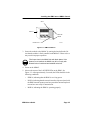
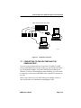
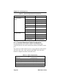
1
IRM3 SN RESET PWR MGMT CLN ON BOK RCV POK PWR A U I IRM3 INTELLIGENT REPEATER MODULE USER’S GUIDE ON LNK T X F O I R L R X U P S C O N S O L E ETHERNET IRM3 QUICK REFERENCE CARD LED INDICATORS LED Description PWR IRM3 is receiving power from MMAC. BOK LED lit-Board is operating properly. IRM3 SN RESET LED not lit-Initialization problem. Press Reset switch. RCV IRM3 is repeating packet received from a connected segment. MGMT IRM3 is receiving/transmitting management packets. CLN Collision detected on a segment. POK Internal repeater port is OK. ON (AUI) AUI port is active repeater port. Fiber Optic port is active repeater port. LNK (FO) Link is established between port and Fiber Optic device. BOK RCV POK ON PWR A U I PWR (AUI) AUI port is receiving power. ON (FO) PWR MGMT CLN ON LNK T X F O CONNECTIONS AUI Port: 15-pin D type receptacle Pin Signal Pin 6 Signal Pin Power Return 11 Signal 1 Logic Ref Logic Ref 2 Collision+ 7 No Connection 12 Receive- 3 Transmit+ 8 Logic Ref 13 Power (+12Vdc) 4 Logic Ref 9 Collision- 14 Logic Ref 5 Receive+ 10 Transmit- 15 No Connection Console/Modem Port: Standard 9-pin RS232 port Pin Signal Pin Signal 1 Carrier Detect (CD) 6 Receive Clock (RXCL) 2 Transmit (TXD) 7 Request to Send (RTS) 3 Receive (RXD) 8 Clear to Send (CTS) 4 Data Terminal Ready (DTR) 9 Ring Indicator (RI) 5 Logic Ref IRM3 User’s Guide Part of 9030494 -01 IRM3 QUICK REFERENCE CARD JUMPER SETTINGS Jumper H1 JP1 H6 and H8 Function Setting Default Enables/Disables Battery. When enabled, user-entered parameters are saved if power to the IRM3 fails. When disabled, parameters are lost. Enable: Jumper over pins 1 and 2 Makes IRM3 compatible with any THN-MIMs being used in the MMAC. This jumper is set for THN-MIMs with part numbers 9000043-06 and above and for THN-MIMs with part numbers below 9000043-06. 9000043-06 and up: Jumper over pins 2 and 3 Sets IRM3 console and modem ports for either internal (signal generated by IRM3) or external (signal generated by attached device) Request to Send (RTS) and Clear to Send (CTS) signals. Internal: Jumper over pins 1 and 2 Disable Disable: Jumper over pins 2 and 3 Jumper over pins 2 and 3 Below 9000043-06: Jumper over pins 1 and 2 If using both, set over 1 and 2 External External: Jumper over pins 2 and 3 Battery Enable/Disable For Cabletron Use Only H1 H2 H4 H3 H5 JP1 H8 H6 CTS-Modem Port CTS-Console Port THN-MIM Jumper 0494104 1 H1/JP1 Pin Numbers 2 3 Part of 9030494-01 H6/H8 Pin Numbers 1 2 3 IRM3 User’s Guide NOTICE Cabletron Systems reserves the right to make changes in specifications and other information contained in this document without prior notice. The reader should in all cases consult Cabletron Systems to determine whether any such changes have been made. The hardware, firmware, or software described in this manual is subject to change without notice. IN NO EVENT SHALL CABLETRON SYSTEMS BE LIABLE FOR ANY INCIDENTAL, INDIRECT, SPECIAL, OR CONSEQUENTIAL DAMAGES WHATSOEVER (INCLUDING BUT NOT LIMITED TO LOST PROFITS) ARISING OUT OF OR RELATED TO THIS MANUAL OR THE INFORMATION CONTAINED IN IT, EVEN IF CABLETRON SYSTEMS HAS BEEN ADVISED OF, KNOWN, OR SHOULD HAVE KNOWN, THE POSSIBILITY OF SUCH DAMAGES. Copyright 1996 by Cabletron Systems, Inc., P.O. Box 5005, Rochester, NH 03866-5005 All Rights Reserved Printed in the United States of America Order Number: 9030494-01 January 1996 SPECTRUM, LANVIEW, MicroMMAC, and BRIM are registered trademarks and Element Manager, EPIM, EPIM-A, EPIM-F1, EPIM-F2, EPIM-F3, EPIM-T, EPIM-X, FOT-F, FOT-F3, HubSTACK, IRM3, SEH, SEHI, and TMS-3 are trademarks of Cabletron Systems, Inc. All other product names mentioned in this manual may be trademarks or registered trademarks of their respective companies. Printed on IRM3 User’s Guide Recycled Paper i Notice FCC NOTICE This device complies with Part 15 of the FCC rules. Operation is subject to the following two conditions: (1) this device may not cause harmful interference, and (2) this device must accept any interference received, including interference that may cause undesired operation. NOTE: This equipment has been tested and found to comply with the limits for a Class A digital device, pursuant to Part 15 of the FCC rules. These limits are designed to provide reasonable protection against harmful interference when the equipment is operated in a commercial environment. This equipment uses, generates, and can radiate radio frequency energy and if not installed in accordance with the operator’s manual, may cause harmful interference to radio communications. Operation of this equipment in a residential area is likely to cause interference in which case the user will be required to correct the interference at his own expense. WARNING: Changes or modifications made to this device which are not expressly approved by the party responsible for compliance could void the user’s authority to operate the equipment. DOC NOTICE This digital apparatus does not exceed the Class A limits for radio noise emissions from digital apparatus set out in the Radio Interference Regulations of the Canadian Department of Communications. Le présent appareil numérique n’émet pas de bruits radioélectriques dépassant les limites applicables aux appareils numériques de la class A prescrites dans le Règlement sur le brouillage radioélectrique édicté par le ministère des Communications du Canada. VCCI NOTICE This equipment is in the 1st Class Category (information equipment to be used in commercial and/or industrial areas) and conforms to the standards set by the Voluntary Control Council for Interference by Information Technology Equipment (VCCI) aimed at preventing radio interference in commercial and/or industrial areas. Consequently, when used in a residential area or in an adjacent area thereto, radio interference may be caused to radios and TV receivers, etc. Read the instructions for correct handling. ii IRM3 User’s Guide Notice CABLETRON SYSTEMS, INC. PROGRAM LICENSE AGREEMENT IMPORTANT: Before utilizing this product, carefully read this License Agreement. This document is an agreement between you, the end user, and Cabletron Systems, Inc. (“Cabletron”) that sets forth your rights and obligations with respect to the Cabletron software program (the “Program”) contained in this package. The Program may be contained in firmware, chips or other media. BY UTILIZING THE ENCLOSED PRODUCT, YOU ARE AGREEING TO BECOME BOUND BY THE TERMS OF THIS AGREEMENT, WHICH INCLUDES THE LICENSE AND THE LIMITATION OF WARRANTY AND DISCLAIMER OF LIABILITY. IF YOU DO NOT AGREE TO THE TERMS OF THIS AGREEMENT, PROMPTLY RETURN THE UNUSED PRODUCT TO THE PLACE OF PURCHASE FOR A FULL REFUND. CABLETRON SOFTWARE PROGRAM LICENSE 1. LICENSE. You have the right to use only the one (1) copy of the Program provided in this package subject to the terms and conditions of this License Agreement. You may not copy, reproduce or transmit any part of the Program except as permitted by the Copyright Act of the United States or as authorized in writing by Cabletron. 2. OTHER RESTRICTIONS. You may not reverse engineer, decompile, or disassemble the Program. 3. APPLICABLE LAW. This License Agreement shall be interpreted and governed under the laws and in the state and federal courts of New Hampshire. You accept the personal jurisdiction and venue of the New Hampshire courts. EXCLUSION OF WARRANTY AND DISCLAIMER OF LIABILITY 1. EXCLUSION OF WARRANTY. Except as may be specifically provided by Cabletron in writing, Cabletron makes no warranty, expressed or implied, concerning the Program (including its documentation and media). CABLETRON DISCLAIMS ALL WARRANTIES, OTHER THAN THOSE SUPPLIED TO YOU BY CABLETRON IN WRITING, EITHER EXPRESSED OR IMPLIED, INCLUDING BUT NOT LIMITED TO IMPLIED WARRANTIES OF MERCHANTABILITY AND FITNESS FOR A PARTICULAR PURPOSE, WITH RESPECT TO THE PROGRAM, THE ACCOMPANYING WRITTEN MATERIALS, AND ANY ACCOMPANYING HARDWARE. 2. NO LIABILITY FOR CONSEQUENTIAL DAMAGES. IN NO EVENT SHALL CABLETRON OR ITS SUPPLIERS BE LIABLE FOR ANY DAMAGES WHATSOEVER (INCLUDING, WITHOUT LIMITATION, DAMAGES FOR LOSS OF BUSINESS, PROFITS, BUSINESS INTERRUPTION, LOSS OF BUSINESS INFORMATION, SPECIAL, INCIDENTAL, CONSEQUENTIAL, OR RELIANCE DAMAGES, OR OTHER LOSS) ARISING OUT OF THE USE OR INABILITY TO USE THIS CABLETRON PRODUCT, EVEN IF CABLETRON HAS BEEN ADVISED OF THE POSSIBILITY OF SUCH DAMAGES. BECAUSE SOME STATES DO NOT ALLOW THE EXCLUSION OR LIMITATION OF LIABILITY FOR CONSEQUENTIAL OR INCIDENTAL DAMAGES, OR ON THE DURATION OR LIMITATION OF IMPLIED WARRANTIES, IN SOME INSTANCES THE ABOVE LIMITATIONS AND EXCLUSIONS MAY NOT APPLY TO YOU. IRM3 User’s Guide iii Notice UNITED STATES GOVERNMENT RESTRICTED RIGHTS The enclosed product (a) was developed solely at private expense; (b) contains “restricted computer software” submitted with restricted rights in accordance with Section 52227-19 (a) through (d) of the Commercial Computer Software - Restricted Rights Clause and its successors, and (c) in all respects is proprietary data belonging to Cabletron and/or its suppliers. For Department of Defense units, the product is licensed with “Restricted Rights” as defined in the DoD Supplement to the Federal Acquisition Regulations, Section 52.227-7013 (c) (1) (ii) and its successors, and use, duplication, disclosure by the Government is subject to restrictions as set forth in subparagraph (c) (1) (ii) of the Rights in Technical Data and Computer Software clause at 252.2277013. Cabletron Systems, Inc., 35 Industrial Way, Rochester, New Hampshire 03867-0505. iv IRM3 User’s Guide CONTENTS CHAPTER 1 INTRODUCTION 1.1 Using This Manual....................................................................... 1-1 1.2 The Intelligent Repeater Module (IRM3) ..................................... 1-2 1.3 IRM3 Front Panel ........................................................................ 1-4 1.3.1 IRM3 Features ................................................................ 1-5 1.4 Repeater Functionality................................................................. 1-5 1.5 Network Management Capabilities.............................................. 1-6 1.6 Getting Help................................................................................. 1-7 1.7 Document Conventions ............................................................... 1-8 1.8 Related Manuals.......................................................................... 1-9 CHAPTER 2 NETWORK PLANNING AND CONFIGURATION 2.1 Network Requirements ................................................................ 2-1 2.1.1 802.3 Repeater Requirements........................................ 2-1 2.1.2 AUI Port Requirements ................................................... 2-1 2.1.3 Fiber Optic Port Requirements ....................................... 2-2 2.2 The IRM3 in the Multi Media Access Center ............................... 2-3 2.2.1 Media Interface Modules ................................................ 2-4 2.3 Sample Network Configuration.................................................... 2-5 CHAPTER 3 INSTALLING THE IRM3 3.1 Unpacking the IRM3 .................................................................... 3-1 3.2 Setting the IRM3 Jumpers ........................................................... 3-2 3.2.1 Setting the Battery Enable/Disable Jumper (H1) ............ 3-2 3.2.2 Setting the CTS External/Internal Jumper (H6, H8)........ 3-3 3.2.3 Setting the THN-MIM Jumper (JP1)................................ 3-4 3.3 Installing the IRM3 into an MMAC Chassis ................................. 3-4 3.4 Pre-installation Test..................................................................... 3-7 3.5 Connecting the IRM3 to the Network........................................... 3-8 3.5.1 Connecting to the Network Through the AUI Port .......... 3-9 3.5.2 Connecting to the Network Through the Fiber Optic Port3-10 3.6 Installation Checkout ................................................................. 3-12 3.7 Connecting to the UPS Through the Console Port.................... 3-13 IRM3 User’s Guide v Contents CHAPTER 4 LOCAL MANAGEMENT 4.1 Accessing Local Management Using a Terminal .........................4-3 4.1.1 Configuring a Local Management Terminal ....................4-3 4.1.2 Terminal Attachment Cable Configuration ......................4-4 4.1.3 Connecting the Terminal and Accessing Local Management4-5 4.2 Accessing Local Management Using a Modem ...........................4-7 4.2.1 Modem Configurations ....................................................4-7 4.2.2 Modem Attachment Cable Configuration ........................4-7 4.2.3 Connecting the Modem and Accessing Management.....4-8 4.3 The Password Screen..................................................................4-9 4.4 The Device/Board/Port Counters Screen...................................4-10 4.4.1 Configuring the Device/Board/Port Counters Screen....4-11 4.4.2 Device/Board/Port/Counters Screen Fields...................4-12 4.4.3 Resetting the Device/Board/Port Counters ...................4-13 4.4.4 Using the Enable Board/Disable Board Options ...........4-14 4.4.5 Using the Enable Port/Disable Port Option ...................4-14 4.4.6 Available Options from the Device/Board/Port Counters Screen4-14 4.5 Community Names Screen ........................................................4-15 4.5.1 Accessing the Community Names Screen ....................4-16 4.5.2 Community Names Screen Fields.................................4-16 4.5.3 Editing the Community Names Screen .........................4-17 4.6 The Setup Screen ......................................................................4-18 4.6.1 Accessing the Setup Screen .........................................4-19 4.6.2 Setup Screen Fields ......................................................4-19 4.6.3 Setting the Set IP Address Option.................................4-20 4.6.4 Setting the Set Current Date Option..............................4-21 4.6.5 Setting the Set Current Time Option .............................4-21 4.6.6 Setting the Device Lock Option .....................................4-21 4.6.7 Setting the Set Refresh Time Option.............................4-22 4.7 Port Association Screen.............................................................4-22 4.7.1 Accessing the Port Association Option .........................4-22 4.7.2 Port Association Screen Fields .....................................4-23 4.7.3 Changing the Port Association ......................................4-24 4.8 The Token Ring Board Status Screen .......................................4-24 4.8.1 Accessing the Token Ring Board Status Screen ..........4-25 4.8.2 Token Ring Board Status Screen Fields .......................4-26 4.8.3 Editing the Token Ring Board Status Screen................4-29 vi IRM3 User’s Guide Contents CHAPTER 5 TROUBLESHOOTING 5.1 Using LANVIEW .......................................................................... 5-1 5.2 Troubleshooting Checklist ........................................................... 5-4 5.3 Using the Reset Switch ............................................................... 5-5 5.4 Before Calling Technical Support ................................................ 5-5 APPENDIX A SPECIFICATIONS A.1 Repeater Functionality.................................................................A-1 A.2 AUI Port .......................................................................................A-2 A.3 Fiber Optic Interface ....................................................................A-2 A.4 Console Port................................................................................A-3 A.5 Microprocessors and Memory .....................................................A-3 A.6 Environmental Requirements ......................................................A-3 A.7 Agency Approvals........................................................................A-4 A.8 Service.........................................................................................A-4 A.9 Physical Properties......................................................................A-4 INDEX IRM3 User’s Guide vii CHAPTER 1 INTRODUCTION Welcome to the Cabletron Systems Intelligent Repeater Module (IRM3) User’s Guide. This manual serves as an installation, management, and reference guide for the IRM3, and includes a description of the IRM3 capabilities and special features. The IRM3 provides a high performance IEEE 802.3 repeater with sophisticated network management capabilities for use in a Cabletron Systems Multi Media Access Center (MMAC). 1.1 USING THIS MANUAL Before installing and operating the IRM3, read through this guide to gain a full understanding of its capabilities. It is assumed that you have a general working knowledge of Ethernet or IEEE 802.3 type data communications networks and their physical layer components. This guide is organized as follows: Chapter 1, Introduction, describes the capabilities of the IRM3, including an explanation of the IRM3 repeater functionality and its management capabilities. This chapter concludes with instructions on how to get help if needed and a list of related manuals. Chapter 2, Network Planning and Configuration, provides configuration requirements to consider before installing the IRM3. This chapter also includes a sample configuration for the IRM3. Chapter 3, Installing the IRM3, contains instructions for installing the IRM3 into an MMAC. This chapter also includes instructions for connecting the IRM3 to the network. IRM3 User’s Guide Page 1-1 Chapter 1: Introduction Chapter 4, Local Management, describes Local Management (LM) and control capabilities for the IRM3. Local Management provides the tools to manage the IRM3 and its attached segments. Chapter 5, Troubleshooting, details the LANVIEW LEDs incorporated into the IRM3, which enable you to quickly diagnose any problems that may occur with the IRM3. This chapter also includes a troubleshooting checklist, procedures for using the reset switch and instructions for calling technical support. Appendix A, Specifications, contains location requirements and operating specifications for the IRM3. 1.2 THE INTELLIGENT REPEATER MODULE (IRM3) The Intelligent Repeater Module (IRM3) (Figure 1-1) is the heart of the Cabletron Systems Multi Media Access Center (MMAC). The IRM3 incorporates a high performance IEEE 802.3 repeater to allow maximum data paths between devices connected to the MMAC. The IRM3 is Simple Network Management Protocol (SNMP) compliant, and can be controlled and monitored by a variety of SNMP Network Management packages. These include Cabletron Systems SPECTRUM Element Manager for Windows, Cabletron Systems SPECTRUM, and third party SNMP network management packages. Additionally, the IRM3 can be controlled and monitored by IRM3/LM - Local Management for the IRM3 through a terminal connected locally or through a Hayes compatible modem. Page 1-2 IRM3 User’s Guide The Intelligent Repeater Module (IRM3) . IRM3 SN RESET PWR BOK MGMT RCV POK CLN ON PWR A U I ON LNK T X F O I R L R X U P S C O N S O L E ETHERNET 0494101 Figure 1-1 IRM3 User’s Guide Intelligent Repeater Module (IRM3) Page 1-3 Chapter 1: Introduction 1.3 IRM3 FRONT PANEL The IRM3 incorporates two ports that connect to external network segments: • One pair of IEEE 802.3 FOIRL fiber optic ports. The fiber optic ST port accommodates a wide variety of multimode fiber optic cable, including 50/125 µm, 62.5/125 µm, and 100/140 µm fiber optic cable, up to 2 km in length. • An IEEE 802.3 compliant AUI port. The AUI port allows you to connect the module to a variety of Ethernet transmission media including twisted pair, fiber optic, and/or thick or thin Ethernet coaxial cable by way of an external transceiver. Either one of these ports can act as the repeater port to the external network. When the IRM3 is first powered up, the AUI port acts as the repeater port and the fiber ports are off. Using the IRM3 network management capabilities (see Chapter 4, Local Management), you can reverse this configuration to have the fiber port act as the repeater port and have the AUI port off. This configuration allows you to connect the IRM3 to a fiber optic link segment directly without having to use an external fiber optic transceiver. The IRM3 also provides the option, through remote management, to set one port as the active repeater port and the other port as a redundant repeater port. Built into the front panel of the IRM3 are two standard 9-pin RS232 console ports labeled CONSOLE and UPS. The CONSOLE port enables you to access the IRM3/LM locally or remotely using a Hayes compatible modem. If you are using a CS-600R/CS-1250R series Uninterruptible Power Source (UPS), the UPS port enables you to monitor and control the UPS through the IRM3 using SPECTRUM Element Manager for Windows or SPECTRUM. The front panel also has a reset switch to initialize the IRM3 processor. The IRM3 incorporates the Cabletron Systems LANVIEW Status Monitoring and Diagnostic System. If a problem arises, such as a power failure or a cable fault, the LANVIEW LEDs (see Section 5.1, Using LANVIEW) help you to diagnose it. Page 1-4 IRM3 User’s Guide Repeater Functionality The LANVIEW LEDs on the IRM3 indicate the following conditions: • The IRM3 is receiving power • An error has been detected with the IRM3 • The IRM3 is receiving packets from any segment connected to the MMAC • The IRM3 is detecting a collision from the network 1.3.1 IRM3 Features There are a number of features that provide for efficient use and maintenance of the IRM3. These features include the following: • Flash EPROM. This feature enables you to upgrade the IRM3 without replacing firmware. Flash EPROMs can be updated remotely by downloading the new software by way of Cabletron Systems SPECTRUM Element Manager for Windows. • Thermal Sensors. These sensors warn the management station if the IRM3 begins to overheat. • Ethernet SNMP Proxy. With SNMP proxy, you can use IRM3 remote management to control power settings for the American Power Conversion’s uninterruptible power source (UPS). • Connect the UPS to the IRM3 UPS port to control the power supply through an SNMP compliant network management tool, such as Cabletron Systems SPECTRUM Element Manager for Windows and SPECTRUM. 1.4 REPEATER FUNCTIONALITY The IEEE 802.3 compliant repeater on the IRM3 provides the MMAC with the ability to achieve maximum data paths on all Ethernet transmission media, including 10BASE-T, fiber optic, and thick or thin Ethernet type cabling. To attain maximum data paths, the IRM3 retimes IRM3 User’s Guide Page 1-5 Chapter 1: Introduction data packets and regenerates the preamble of each data packet that enters the MMAC. In addition, IRM3 repeater functionality assures that problem segments connected to any port on the MMAC do not affect any other segments connected to the MMAC. If 32 consecutive collisions are detected on any segment, or if a collision detector is on for more than 2.4 ms, the IRM3 automatically partitions that segment. The segment automatically reconnects to the MMAC after a packet is transmitted onto the segment without causing a collision. 1.5 NETWORK MANAGEMENT CAPABILITIES The Cabletron Systems IRM3 can be controlled and managed by a variety of network management packages which include the following: • Cabletron Systems SPECTRUM • Cabletron Systems SPECTRUM Element Manager for Windows • Cabletron Systems IRM3/LM (Local Management) • Third Party SNMP compliant Network Management Packages The IRM3 network management capabilities provide the necessary management tools for the IRM3 to operate at its full capacity. Your ability to set up parameters within the network management capabilities ensures optimal performance of the IRM3, and, hence, the network. For example, a great deal of statistical information on the port, board, and MMAC device level is gathered by the IRM3, including each of the following: • Packets • Bytes Received • Collisions • Giant Packets • Runt Packets • Misaligned Packets • Frame Size • Out of Window Collisions • Breakdowns • CRC Errors Page 1-6 IRM3 User’s Guide Getting Help To help you see how your network is being used, and to help you plan for future network use, the IRM3 also provides Ethernet protocol counters on the port and board level for the following protocols: • • • • • • • • • AppleTalk Banyan Cabletron DECnet ISO/OSI Novell TCP/IP XNS Other For further specific information on in-band management of the IRM3, refer to the applicable Network Management Package User’s Manual. 1.6 GETTING HELP If you need additional support related to the IRM3, or if you have any questions, comments, or suggestions related to this manual, contact Cabletron Systems Technical Support: By phone By CompuServe By Internet mail: By FTP IRM3 User’s Guide (603) 332-9400 Monday–Friday, 8 A.M – 8 P.M. Eastern time GO CTRON from any ! prompt [email protected] ctron.com (134.141.197.25) Login: anonymous Password: your email address Page 1-7 Chapter 1: Introduction Before calling Cabletron Systems Technical Support, be prepared to provide the following information: • A detailed description of the failure. • A description of any action already taken to resolve the problem (swapping the bad unit with a unit known to work properly, etc.) • A description of your network (environment, layout, cable type and length, etc.) • Serial numbers of all Cabletron Systems products used in the network. • Revision level of all Cabletron Systems products in the network • Revision level of firmware installed on all Cabletron Systems products • The network load and frame size at the time of the failure, if known • Product history (had the product been returned previously, did it have the same problem, etc.) • The RMA number generated, if any 1.7 DOCUMENT CONVENTIONS The following conventions are used throughout this document: NOTE NOTE symbol. Calls the reader’s attention to any item of information that may be of special importance. TIP symbol. Conveys helpful hints concerning procedures or actions. TIP ! CAUTION symbol. Contains information essential to avoid damage to the equipment. CAUT ION WARNING Page 1-8 WARNING symbol. Warns against an action that could result in equipment damage, personal injury or death. IRM3 User’s Guide Related Manuals 1.8 RELATED MANUALS The manuals listed below should be used to supplement the procedures and other technical data provided in this manual. The procedures will be referenced where appropriate, but will not be repeated. Cabletron Systems Multi Media Access Center Overview and Setup Guide. Cabletron Systems IRM3 Management Module Guide for Microsoft Windows. IRM3 User’s Guide Page 1-9 CHAPTER 2 NETWORK PLANNING AND CONFIGURATION This chapter addresses some of the configuration issues that you should consider when installing the IRM3, including 802.3 standards related to repeaters, transceivers, and cables. This chapter also gives an overview of Cabletron Systems Multi Media Access Center (MMAC) and the Media Interface Modules (MIM) that can be managed by the IRM3. Finally, an example of a network configuration using the IRM3 is provided. 2.1 NETWORK REQUIREMENTS When connecting network segments to the IRM3, you must follow the network guidelines listed below. 2.1.1 802.3 Repeater Requirements Depending on the size of your network, you may need to use multiple repeaters. When planning your network, keep in mind that 802.3 standards allow for no more than four repeaters in one data path. If your network requires more than four repeaters, use a bridge to create a new data path. 2.1.2 AUI Port Requirements The IRM3 provides the flexibility of connecting to a network with different types of media through the AUI port. Using an AUI cable along with the proper Cabletron Systems transceiver, you can connect to the network with AUI cable, coaxial cable, twisted pair cable, or fiber optic cable. IRM3 User’s Guide Page 2-1 Chapter 2: Network Planning and Configuration When connecting a network segment to the IRM3 through a transceiver and an AUI cable, the following requirements must be met: • The transceiver to which the IRM3 will be connected must meet Ethernet Version 1, Version 2 or IEEE 802.3 standards. • The AUI cables connecting the IRM3 to the transceiver on the network must be IEEE 802.3 type cables and must not exceed 50 meters in length. • The Signal Quality Error (SQE) function on the transceiver must be disabled. The SQE function is used to confirm that the collision signaling of the transceiver is working properly. However, when connecting a transceiver to the IRM3, or any other repeater, you must disable the SQE test function. If SQE is not disabled, the repeater regards each SQE signal as a collision and resends the JAM packet, causing a considerable slowdown of network operations. NOTE 2.1.3 Fiber Optic Port Requirements When connecting a Fiber Optic Link Segment to the IRM3 fiber optic ST ports, the following requirements must be met: • Cable Type - The fiber optic link segment should consist of one of the following: - • 50/125 µm fiber optic cabling 62.5/125 µm fiber optic cabling 100/140 µm fiber optic cabling Attenuation - The fiber optic cable must be tested with a fiber optic attenuation test set that is adjusted for an 850 nm wavelength. This test verifies that the signal loss in a cable is within an acceptable level: - 13.0 dB or less for 50/125 µm fiber cable segment 16.0 dB or less for 62.5/125 µm fiber cable segment 19.0 dB or less for 100/140 µm fiber cable segment Page 2-2 IRM3 User’s Guide The IRM3 in the Multi Media Access Center • Budget and Propagation Delay - When determining the maximum fiber optic cable length, the fiber optic budget delay and total network propagation should be calculated and taken into consideration before fiber runs are incorporated in any network design. Fiber optic budget is the combination of the optical loss due to the fiber optic cable, in-line splices, and fiber optic connectors. Propagation delay is the amount of time it takes a packet to travel from the sending device to the receiving device. • Length - IEEE 802.3 specifications for fiber optic cable allow for a maximum of 1 km. However, distances of at least 2 km can usually be achieved. 2.2 THE IRM3 IN THE MULTI MEDIA ACCESS CENTER The IRM3 is designed to be installed in a Cabletron Systems Multi Media Access Center (MMAC) network hub with the Flexible Network Bus (FNB) - See Figure 2-1. The MMAC is fully protocol independent and is available in an eight slot (MMAC-M8FNB), five slot (MMAC-M5FNB) and three slot (MMAC-M3FNB) model. When installed in an MMAC, the IRM3 supports 10 Mbps Ethernet (IEEE 802.3), as well as 4 and 16 Mbps Token Ring (IEEE 802.5) Media Interface Modules (MIMs) using shielded twisted pair (STP) or unshielded twisted pair (UTP), fiber optic, thin or thick coaxial and standard AUI transceiver cabling. The IRM3 retimes and regenerates packets for each port of each Ethernet MIM installed in the MMAC, and allows users to access management information for all Token Ring and Ethernet MIMs in the MMAC. Power & Management Bus Ethernet A Bus Flexible Network Bus Ethernet B Bus Ethernet C Bus 0494102 Figure 2-1 IRM3 User’s Guide MMAC with FNB Page 2-3 Chapter 2: Network Planning and Configuration 2.2.1 Media Interface Modules The following is a description of the types of Cabletron Systems MIMs that can be installed in the MMAC and managed by the IRM3. THN-MIM Thin Coaxial Module The THN-MIM has 12 Ethernet/IEEE 802.3 compliant attachments to either thin or thick coaxial cable through a thick-to-thin adapter. The thin coaxial segment, which may be up to 185 meters in length, can accommodate up to 29 connections per segment. The thick coaxial segment may extend to 500 meters in length and provide up to 99 connections. MT8-MIM Multiport Transceiver Interface Module The MT8-MIM provides eight separate transceivers in one unit that can be inserted into the MMAC. The MT8-MIM provides eight IEEE 802.3-compatible medium attachment unit (MAU) ports, which allows a direct connection to any type of media. TPMIM 10BASE-T Modules Cabletron Systems TPMIM 10BASE-T modules are available with 12 or 24 ports equipped with DB9, RJ45, or RJ71 connectors for shielded/unshielded twisted pair connections of up to 125 meters in length. FOMIM Fiber Optic Modules Cabletron Systems FOMIM fiber optic modules are available with 6, 12 or 18 ports equipped with either ST (straight tip) or SMA (subminiature type A) connectors, with models that support either single mode or multimode cable. The FOMIMs provide Ethernet/IEEE 802.3 Fiber Optic Inter Repeater Link (FOIRL) compatible attachments over 50, 62.5 or 100 µm core multimode fiber cabling, or 8/125 - 12/125 µm core single mode cabling. Each port of the multimode modules can drive fiber optic link segments up to 2 km in length. Each port on the single mode modules can drive fiber segments up to 10 km, provided that system budgets are met. Page 2-4 IRM3 User’s Guide Sample Network Configuration TRMIM Token Ring Modules Cabletron Systems TRMIM Token Ring modules are available with 12 or 24 ports equipped with either RJ45 or DB9 connectors. Token Ring modules that support unshielded twisted pair (UTP) cable provide for segments of up to 100 meters. With modules that support shielded twisted pair (STP) cable, you can attach segments of up to 200 meters. 2.3 SAMPLE NETWORK CONFIGURATION The following illustrates a simple network configuration that provides a general idea of how the IRM3 can be used in a network. Each workstation will have access to each other and the server through the TPMIM and the IRM3. The IRM3 manages the backplane and repeating functions between the users on the network. The TPMIM provides access to the backplane for the workstations while the IRM3 repeats the incoming traffic to the other stations on the network. Control of the boards and ports is accessed through the IRM3 Local Management. MMAC3 with IRM3 Server 0494103 Workstations Figure 2-2 IRM3 User’s Guide Example of a Small Network Configuration Page 2-5 CHAPTER 3 INSTALLING THE IRM3 This chapter provides the instructions needed to install and verify the proper operation of the IRM3 into a network. The information in this chapter pre-supposes that the previous sections have been completed properly. To install and test the IRM3 perform the following: • Unpack the IRM3 • Set and verify the IRM3 jumper settings • Install the IRM3 into an MMAC chassis • Perform pre-installation checkout • Connect to the network through either of the following: - AUI port Fiber Optic port • Perform installation checkout • Connect UPS (if required) 3.1 UNPACKING THE IRM3 Before installing the IRM3, visually inspect the module. To unpack the module, proceed as follows: 1. Remove the shipping material covering the IRM3 in the shipping box. 2. Carefully remove the module from the shipping box. Leave the module in its conductive bag until you are ready to install it. Save the shipping box and materials in the event the unit has to be reshipped. 3. Visually inspect the module. If you see any damage, contact Cabletron Systems Technical Support immediately. IRM3 User’s Guide Page 3-1 Chapter 3: Installing the IRM3 3.2 SETTING THE IRM3 JUMPERS There are eight jumpers on the IRM3 as shown in Figure 3-1. Four of the jumpers, H1, H6, H8, and JP1 can be changed. The remaining jumpers are for Cabletron Systems use only and should not be changed from their default positions. 3.2.1 Setting the Battery Enable/Disable Jumper (H1) The Battery Enable/Disable Jumper (H1, Figure 3-1) allows you to enable or disable the Battery Back-up for RAM on the IRM3. When set to the enabled position, all parameters that you enter into the IRM3 will be saved if power to the MMAC should fail, or if the IRM3 is removed from the MMAC. When set to the disabled position, all parameters entered into the IRM3 will be lost if power is removed from the IRM3. To set the Battery Enable/Disable Jumper perform the following: • To enable the battery back-up , place the jumper over Pins 1 and 2. • To disable the battery back-up, place the jumper over Pins 2 and 3. This is the position in which the IRM3 is shipped. Page 3-2 IRM3 User’s Guide Setting the IRM3 Jumpers Battery Enable/Disable For Cabletron Use Only H1 H2 H4 H3 H5 JP1 H8 H6 CTS-Modem Port CTS-Console Port THN-MIM Jumper 0494104 1 H1/JP1 Pin Numbers 2 3 Figure 3-1 H6/H8 Pin Numbers 1 2 3 IRM3 Jumper Locations 3.2.2 Setting the CTS External/Internal Jumper (H6, H8) The IRM3 UPS port and CONSOLE port are RS232 interfaces that use Request to Send (RTS), Clear to Send (CTS), and Data Terminal Ready (DTR) to control data flow. If the device connected to either the UPS port or CONSOLE port does not provide RTS or DTR, the IRM3 must be configured to compensate (internally) for the lack of these signals. In those situations, the CTS External/Internal jumpers (H6 for the UPS port and H8 for the CONSOLE port) allow the IRM3 to generate the CTS signal internally. Refer to the Users Manual of the device to determine the requirements for this jumper setting. IRM3 User’s Guide Page 3-3 Chapter 3: Installing the IRM3 Set the CTS External/Internal Jumper as follows: • If RTS or DTR is generated by your device to the IRM3, place the jumper over pins 2 and 3. This is the position in which the IRM3 is shipped. • If RTS or DTR must be generated internally by the IRM3, place the jumper over pins 1 and 2. 3.2.3 Setting the THN-MIM Jumper (JP1) The THN-MIM Jumper (JP1, Figure 3-1) may need to be set depending on the revision level of the THN-MIMs installed in your MMAC. To check the revision level of the THN-MIM, refer to the part number located in the lower left corner of the module (same side as the backplane connector). Set the THN-MIM Jumper as follows: • If you are using THN-MIM part numbers 9000043-06 and above in your MMAC, place the jumper over pin 2 and pin 3. This is the position in which the IRM3 is shipped. • If you are using THN-MIM part numbers 9000043-05 and below in your MMAC, place the jumper over pin 1 and pin 2. ! CAUT ION If THN-MIM part numbers 9000043-05 and below and 9000043-06 and above are both installed in your MMAC, the THN-MIM Jumper must be placed over pin 1 and pin 2. 3.3 INSTALLING THE IRM3 INTO AN MMAC CHASSIS The IRM3 is designed to be installed into slot 1 of any MMAC. No special skills or tools are required to install the IRM3. To install the IRM3 into an MMAC, continue as follows: 1. Power off the MMAC. 2. Slide the IRM3 (Figure 3-2) into Slot 1 of the MMAC card cage. Be sure that the card is in the top and bottom slot guides. Page 3-4 IRM3 User’s Guide Installing the IRM3 into an MMAC Chassis IRM-3 MMAC-8 KNURLED KNOBS BOARD SLOT 1 Figure 3-2 0494105 IRM3 Installation 3. Secure the module to the MMAC by turning the knurled knobs. Be sure that the module is firmly attached to the MMAC. Failure to do so may result in improper operation. WARNING Fill all open slots in the MMAC hub with blank plates. If the plates are not installed, the MMAC may fail to comply with allowed limits of conducted and radiated emissions. 4. Power on the MMAC. 5. Observe the status of the LANVIEW LEDs on the IRM3. See Figure 3-3. After approximately 2 seconds, the LEDs should be in the following conditions: • PWR lit, indicating that the IRM3 is receiving power. • POK lit, indicating that the network interface chip associated with the IRM3 internal repeater ports have passed the internal loopback test and are now ready for transmission. • BOK lit, indicating the IRM3 is operating properly. IRM3 User’s Guide Page 3-5 Chapter 3: Installing the IRM3 IRM3 SN RESET SWITCH RESET PWR MGMT CLN BOK RCV POK ON PWR LANVIEW LEDS A U I ON LNK T X F O 0494106 Figure 3-3 NOTES LANVIEW LEDs When the IRM3 is first powered up, the AUI port acts as the repeater port and the Fiber ports are off. This configuration can be altered using IRM3 Local Management or network management tools so that the Fiber ports act as the repeater port and the AUI port is off. Powering off the IRM3 or using the Reset switch will not alter the Repeater port settings if the battery back-up is enabled. For further information, refer to the discussion of Port Association in Chapter 4. Page 3-6 IRM3 User’s Guide Pre-installation Test 3.4 PRE-INSTALLATION TEST Before installing the IRM3 in a live network, test the module in a controlled situation to ensure that it is repeating packets. With the IRM3 installed in an MMAC hub with a Media Interface Module (MIM), this test can be performed with two workstations (Figure 3-1) by completing the following steps: 1. Install a Media Interface Module (TPMIM, FOMIM, THN-MIM, etc.) into the same MMAC chassis as the IRM3. 2. Connect the first workstation to either the MIM, using the appropriate cable and transceiver; or to the IRM3 using either the AUI port, using a transceiver and an AUI cable; or to the fiber optic port, using fiber optic cable; depending on which is the active repeater port. NOTE The AUI port is the default active repeater port. If you want to test the IRM3 using the fiber port, it must be selected through Local Management. Please refer to Chapter 4 for more information on selecting the active repeater port. 3. Connect the second workstation to the MIM, using the appropriate transceivers and cable. 4. Set the first workstation as the file server and the second as the client (refer to the workstation documentation for setting up the workstations as file server and client). When the workstations are properly set up, proceed to send packets between the workstations and verify that the IRM3 is operating properly. NOTE A “ping” test will verify that the IRM3 is operating properly. However, both server and client workstations must have their own unique IP Adresses. If failures occur, refer to the Troubleshooting section in Chapter 5. IRM3 User’s Guide Page 3-7 Chapter 3: Installing the IRM3 MMAC 3/FNB with IRM3 and TPMIM TPT File Server Workstation Client Workstation Figure 3-4 0494109 Pre-installation Test 3.5 CONNECTING THE IRM3 TO THE NETWORK This section provides procedures for connecting the IRM3 to the network using the AUI port or the Fiber Optic ports. Page 3-8 IRM3 User’s Guide Connecting the IRM3 to the Network 3.5.1 Connecting to the Network Through the AUI Port Connect to the network through the AUI port by performing the following steps: ! CAUT ION Be sure to disable the SQE test function on the transceiver you connect to the IRM3 AUI port. Failure to do so will result in improper operation of the IRM3. Refer to the applicable transceiver manual. 1. Attach an external transceiver to the segment to which the AUI port will be attached. Refer to the applicable transceiver manual. 2. Attach the female end of an AUI cable, no more than 50 meters in length, to the transceiver. 3. Attach the male connector on the AUI cable (Figure 3-5) to the AUI port on the IRM3. 4. Move the slide latchon the AUI port to secure it to the lock post on the AUI connector. . SLIDE LATCH SLIDE LATCH AUI PORT AUI PORT AUI AUI CONNECTOR CONNECTOR 0494107 Figure 3-5 IRM3 User’s Guide Connecting to the AUI Port Page 3-9 Chapter 3: Installing the IRM3 3.5.2 Connecting to the Network Through the Fiber Optic Port When connecting a fiber optic link segment to the IRM3 Fiber Optic ports, you must keep the following in mind: • ST connectors attach to ST ports much like BNC connectors attach to BNC ports. The connector is inserted into the port with the alignment slot on the connector inserted into the alignment key on the port. The connector is then turned clockwise to lock it down. • The physical communication link consists of two strands of fiber optic cabling: the Transmit (TX) and the Receive (RX). The Transmit strand from the fiber optic port on the module will be connected to the Receive port of a fiber optic Ethernet device at the other end of the segment. The Receive strand of the fiber optic port on the module will be connected to the Transmit port of the fiber optic Ethernet device. • Label the fiber optic cable to indicate which fiber is Receive and which is Transmit. When you buy fiber optic cable from Cabletron Systems, it is labeled so that at one end of the cable, one fiber is labeled 1, and the other fiber is labeled 2. This pattern is repeated at the other end of the cable. If you did not purchase your cable from Cabletron Systems, be sure to label your cable in this manner. ! CAUT ION Do not touch the ends of the fiber optic strands, and do not let the ends come in contact with dust, dirt, or other contaminants. Contamination of the ends can cause problems in data transmissions. If the ends become contaminated, clean them with denatured alcohol using a soft, clean, lint free cloth. Connect a fiber optic link segment to an IRM3 FOIRL Fiber Optic port by performing the following steps: 1. Remove the protective plastic covers from the fiber optic ports and from the ends of the connectors on each fiber strand. 2. Attach the fiber labeled 1 (Figure 3-6) to the receive port, labeled RX, on the module. 3. Attach the fiber labeled 2 to the transmit port, labeled TX, on the module. Page 3-10 IRM3 User’s Guide Connecting the IRM3 to the Network 4. At the other end of the fiber optic cable, attach the fiber labeled 1 to the transmit port of the device. 5. Attach the fiber labeled 2 to the receive port. ST Fiber Optic Ports T X R X Fiber 2 ST Connectors Fiber 1 Figure 3-6 0494108 Connecting to the Fiber Optic Ports 6. Check that the LNK LED for the fiber port on the IRM3 is lit (Figure 3-3). If the LED is not lit, perform each of the following steps until it is: a. Check that the power is turned on for the device at the other end of the link. b. Verify that the fiber strands are properly crossed over between the IRM3 and the fiber optic device at the other end of the fiber optic link segment. c. Verify that the fiber cable meets the dB loss specifications outlined in Fiber Optic Port Requirements in Chapter 2, Section 2.1.3. If a link still has not been established, contact Cabletron Systems Technical Support. IRM3 User’s Guide Page 3-11 Chapter 3: Installing the IRM3 3.6 INSTALLATION CHECKOUT After the IRM3 is connected to the network, verify that packets can be passed between the two Ethernet network segments through the IRM3. As in the pre-installation checkout, use two workstations set up as file server and client. Keep the server workstation stationary in the wiring closet with the IRM3, and use the client workstation to move around to each node that is connected to the IRM3 (Figure 3-7). You can verify the installation checkout by performing the following steps: 1. Connect the server workstation to either a MIM, using the appropriate cable and transceiver, or to the IRM3 through either the AUI port, using a transceiver and an AUI cable, or to the Fiber Optic port, using fiber optic cable. 2. Going to each node connected to the MMAC, connect the client workstation and proceed to test the segment. A “ping” test will verify that the IRM3 is operating properly. NOTE If a failure occurrs, refer to Chapter 5, Troubleshooting, for further assistance. Page 3-12 IRM3 User’s Guide Connecting to the UPS Through the Console Port MMAC 3/FNB with IRM3 and TPMIM TPT Office Locations File Server Workstation Client Workstation Figure 3-7 0494110 Installation Checkout 3.7 CONNECTING TO THE UPS THROUGH THE CONSOLE PORT If you are using an American Power Conversion CS-600R/CS-1250R series Uninterruptible Power Source (UPS), you can monitor and control the UPS through the IRM3, using SPECTRUM Element Manager for Windows. To access UPS management from the IRM3, use a serial cable to connect the console port on the IRM3 to the 9-pin RS232 connector on the UPS. Refer to the Cabletron Systems IRM3 Management Module Guide for Microsoft Windows for information on managing the UPS. IRM3 User’s Guide Page 3-13 CHAPTER 4 LOCAL MANAGEMENT The Cabletron Systems IRM3/LM provides unique management and control capabilities for the IRM3. With Local Management for the IRM3, you have the tools to manage the IRM3 and its attached segments. For example, you can enable and disable ports and set parameters such as the IP Address of your IRM3 or its current date and time. You can also use Local Management to view a full array of statistics to the port level. Since the IRM3 is an SNMP compliant device, you can also set community names for the network management stations that will have access to the IRM3. Local Management is accessed either through a VT200 or VT300 series terminal (or terminals running an emulation program), or through a Hayes compatible modem. To set up your terminal or Hayes compatible modem, see Sections 4.1 or 4.2 respectively. This chapter • Explains how to access Local Management for the IRM3 through the CONSOLE port by using either a terminal or Hayes compatible modem. • Discusses the statistical information available concerning your IRM3, and its boards and ports. • Describes the Community Names Option, which allows you to control access to the IRM3 and designate which workstations will receive alarms from the device. • Describes using the IRM3 Setup Option to set the IP Address, current date, and current time for your IRM3. • Explains the Port Association screen, which allows you to set either the AUI port or Fiber Optic Link port on the IRM3 to act as the repeater port. • Describes the Token Ring Board Status screen, which enables you to monitor and manage any Token Ring boards installed in the MMAC. IRM3 User’s Guide Page 4-1 Chapter 4: Local Management Figure 4-1 shows the IRM3/LM screen flow. Enter Password: IRM3 SNMP LOCAL MANAGEMENT INTRODUCTORY SCREEN DEVICE/BOARD PORT/COUNTERS SETUP COMMUNITY NAMES PORT ASSOCIATION TOKEN RING BOARD 0494111 Figure 4-1 Page 4-2 IRM3 Local Management Screen Flow IRM3 User’s Guide Accessing Local Management Using a Terminal 4.1 ACCESSING LOCAL MANAGEMENT USING A TERMINAL This section describes how to access local management using a terminal. Local Management for the IRM3 is accessed through a VT200 or VT300 series terminal, or terminals running emulation programs for these series terminals. The terminal or emulating terminal is attached to the 9-pin port labeled CONSOLE on the IRM3. 4.1.1 Configuring a Local Management Terminal The following section explains how to configure your terminal (console) to communicate with Local Management. Refer to your specific terminal manual for more instructions if necessary. Table 4-1 lists the setup parameters necessary to configure your terminal (console) to communicate with Local Management. If the terminal is a Digital Equipment Corporation VT320 terminal, press F3 to access the Setup Directory. If the local management terminal uses terminal emulation of the VT320, refer to the equipment user manual for setup procedures. Table 4-1 Terminal Setup Parameters Menu Function Selection Display Setup Columns 80 Columns Controls Interpret Controls Auto Wrap No Auto Wrap General Setup IRM3 User’s Guide Test Cursor Cursor Mode 7 Bit Control Cursor Keys Normal Cursor Keys Page 4-3 Chapter 4: Local Management Table 4-1 Terminal Setup Parameters (Continued) Menu Communications Setup Keyboard Setup Function Selection Transmit Transmit = 9600 Receive Receive = Transmit XOFF any option Bits, Parity 8 Bits, No Parity Stop Bit 1 Stop Bit Local Echo No Local Echo Port DEC-423, Data Leads Only Transmit any option Auto Answerback No Auto Answerback Auto Repeat any option Keyclick any option Margin Bell Margin Bell Warning Bell Warning Bell Auto Answerback No Auto Answerback 4.1.2 Terminal Attachment Cable Configuration Local Management is accessed by an RS232 cable available from Cabletron Systems. This cable connects the terminal to the IRM3 Console port. The pin-out for a cable with a 25-pin or a 9-pin connector at the terminal end of the cable, and a 9-pin connector at the IRM3 end of the cable, should be configured as shown in the table below: Table 4-2 9-pin to 25-pin Pinouts 9-Pin Male Connector (IRM3 End) to 25-Pin Female Connector (Terminal End) Pin 3 (Receive) to Pin 2 (Transmit) Pin 2 (Transmit) to Pin 3 (Receive) Pin 5 (Ground) to Pin 7 (Ground) Pin 7 (Request to Send) to Pin 5 (Clear to Send) Pin 8 (Clear to Send) to Pin 20 (Data Terminal Ready) Page 4-4 IRM3 User’s Guide Accessing Local Management Using a Terminal Table 4-3 9-pin to 9-pin Pinouts 9-Pin Male Connector (IRM3 End) to 9-Pin Female Connector (Terminal End) Pin 3 (Receive) to Pin 3 (Transmit) Pin 2 (Transmit) to Pin 2 (Receive) Pin 5 (Ground) to Pin 5 (Ground) Pin 7 (Request to Send) to Pin 8 (Clear to Send) Pin 8 (Clear to Send) to Pin 7 (Request to Send) 4.1.3 Connecting the Terminal and Accessing Local Management This procedure assumes that the 9- to 25-pin RS232 cable, available from Cabletron Systems, is being used to connect the terminal to the IRM3. NOTE If the terminal you are using does not generate a Clear to Send (CTS) signal, Request to Send (RTS) signal, or a Data Terminal Ready (DTR) signal, the CTS jumpers on the IRM3 must be set to compensate for these signals. Refer to Chapter 3 for information on setting the CTS jumper. To access Local Management, proceed as follows: 1. Plug the 9-pin end of the RS232 cable into the RS232 port labeled CONSOLE on the IRM3. 2. Plug the 25-pin end of the RS232 cable into the COMM port on the terminal. 3. Turn the terminal on. The IRM3 Password screen, shown in Figure 4-3 appears. Refer to Section 4.3 for more information regarding this screen. 4. Enter your password. (The default password is the RETURN key.) NOTE If you have entered a Superuser name at the Community Names screen (refer to Section 4.5), the password will be the Superuser name. If you have entered more than one Superuser name, any of those names may be used as the password. IRM3 User’s Guide Page 4-5 Chapter 4: Local Management 5. Press RETURN. The IRM3 SNMP Local Management introductory screen, shown in Figure 4-2, appears on the terminal. IRM3 SNMP LOCAL MANAGEMENT Cabletron Systems Incorporated P.O. Box 5005 Rochester NH, 03867-5005 U.S.A. (603) 332-9400 IRM3 SNMP Version 0.00.xx (C) Copyright Cabletron Systems Inc. 1992 MAIN 0494112 Figure 4-2 IRM3 SNMP Local Management Introductory Screen 6. Press RETURN. The Device/Board/Port Counters screen (Main), shown in Figure 4-4, appears. Refer to Section 4.4 for more information regarding this screen. Local Management for the IRM3 is now ready for operation. Page 4-6 IRM3 User’s Guide Accessing Local Management Using a Modem 4.2 ACCESSING LOCAL MANAGEMENT USING A MODEM Local Management for the IRM3 is accessed through a Hayes, or Hayes Compatible Modem meeting the AT Command Set. The modem is attached to the 9-pin port labeled CONSOLE on the IRM3. 4.2.1 Modem Configurations The modem configuration must be set as follows so that the modem can communicate with the IRM3 Local Management. Refer to your modem manual for instructions on setting the modem. Modem Dialing Out from a PC Data Bits Parity Flow Control Stop Bits 8 None None 1 Modem Connected to the IRM3 Auto Answer On 4.2.2 Modem Attachment Cable Configuration Local Management is accessed by an RS232 cable available from Cabletron Systems. This cable connects the modem to the IRM3 CONSOLE port. The pin-out for a cable with a 25-pin connector at the modem end of the cable, and a 9-pin connector at the IRM3 end of the cable, should be configured as follows: Table 4-4 9-pin to 25-pin Pinouts 9-Pin Male Connector (IRM3 End) to 25-Pin Female Connector (Modem End) Pin 2 (Transmit) to Pin 3 (Receive) Pin 3 (Receive) to Pin 2 (Transmit) Pin 5 (Ground) to Pin 7 (Ground) Pin 7 (Request to Send) to Pin 20 (Data Terminal Ready) Pin 8 (Clear to Send) to Pin 8 (Data Carrier Detect) Pin 9 (Ring Indicator) to Pin 22 (Ring Indicator) IRM3 User’s Guide Page 4-7 Chapter 4: Local Management 4.2.3 Connecting the Modem and Accessing Management NOTE If the modem you are using does not generate a Clear to Send (CTS) signal, Request to Send (RTS) signal, or a Data Terminal Ready (DTR) signal, the CTS jumpers on the IRM3 must be set to compensate for these signals. Refer to Chapter 3 for information on setting the CTS jumper. To access Local Management, proceed as follows: 1. Plug the 9-pin end of the RS232 cable into the RS232 port labeled CONSOLE on the IRM3. 2. Plug the 25-pin end of the cable into the 25-pin MODEM port on the modem. 3. Turn the modem on and dial into the modem connected to the IRM3. The IRM3 Password screen, shown in Figure 4-3, appears once your connection is established. Refer to Section 4.3 for more information on this screen. 4. Enter your password. (The factory default password is the RETURN key.) NOTE If you have entered a Superuser name at the Community Names screen (refer to Section 4.5), the password will be the Superuser name. If you have entered more than one Superuser name, any of those names may be used as the password. 5. Press RETURN. The IRM3 SNMP Local Management introductory screen, shown in Figure 4-2, appears on the terminal. 6. Press RETURN. The Device/Board/Port Counters screen (Main), shown in Figure 4-4, appears. Refer to Section 4.4 for more information on this screen. Local Management for the IRM3 is now ready for operation. Page 4-8 IRM3 User’s Guide The Password Screen 4.3 THE PASSWORD SCREEN When either the terminal or modem are properly connected to the IRM3, the Password screen shown in Figure 4-3 will appear. The Password screen is the first step in accessing the local management screens of the IRM3. Enter Password: 0494113 Figure 4-3 IRM3 Password Screen To access local management continue as follows: 1. Enter your password. (The default password is the RETURN key.) NOTE If you have entered a Superuser name at the Community Names screen (See Figure 4-5), the password will be the Superuser name. If you have entered more than one Superuser name, any of those names may be used as the password. IRM3 User’s Guide Page 4-9 Chapter 4: Local Management 2. Press RETURN. The IRM3 SNMP Local Management introductory screen, shown in Figure 4-2, appears on the terminal. 3. Press RETURN. The Device/Board/Port Counters screen (Main), shown in Figure 4-4, appears. Refer to Section 4.4 for more information regarding this screen. Local Management for the IRM3 is now ready for operation. 4.4 THE DEVICE/BOARD/PORT COUNTERS SCREEN The Device/Board/Port Counters screen shown in Figure 4-4 of Local Management for the IRM3 allows you to quickly scan statistical information concerning the network traffic passing through the MMAC, boards, and ports. You can see the number of bytes received, the total number of packets, the total number of receive and transmit collisions, and the number of errors. DEVICE/BOARD/PORT COUNTERS 11/15/91 14:26:43 Device Name: IRM3 Ethernet Address: 00-00-1d-00-39-14 IP Address: 134.141.52.48 Port 1 Board 1 Device Bytes Received: Packets: Errors: Receive Collisions: Transmit Collisions: Out of Window Collisions: Runt Packets: No Resources Available: Frame Alignment Errors: CRC Errors: Giant Packets Port Admin. Status: ON 42586292 42598357 42598794 141995 14 142314 14 142336 14 1 0 0 0 1 0 2 2 Port Seg. Status: 1 0 0 0 1 0 2 2 ON 1 0 0 0 1 0 2 2 EXIT BOARD 1 PORT 1 RESET COUNTERS COMMUNITY NAMES SETUP ENABLE BOARD DISABLE BOARD ENABLE PORT DISABLE PORT PORT ASSOCIATION TOKEN RING BOARD 3 0494114 Figure 4-4 Page 4-10 IRM3 Device/Board/Port Counters Screen IRM3 User’s Guide The Device/Board/Port Counters Screen The errors are further broken down into the following categories: • Out of Window Collisions • Runt Packets • No Resources Available • Frame Alignment Errors • CRC Errors • Giant Packets You can also perform the following functions: • Reset all counter information associated with the MMAC back to zero. • Enable and disable an individual board. • Enable and disable an individual port. Additionally, you can view Port Administrative and Segmentation Status at this screen. All other management options available for the IRM3 are also accessed from the Device/Board/Port Counters screen. 4.4.1 Configuring the Device/Board/Port Counters Screen When the Device/Board/Port Counters screen (Figure 4-4) first appears, information is displayed for the device (IRM3), Board 1, and Port 1. If you wish to view counter information for another board or port, follow these steps: 1. Using the arrow keys, highlight the appropriate option, BOARD X or PORT X, at the bottom of the Device/Board/Port Counters screen. 2. Press the + key (press SHIFT and + key) to increment the board or port number, or the - key to decrement the board or port number. 3. Press RETURN. Counter information associated with the selected board and port will appear. IRM3 User’s Guide Page 4-11 Chapter 4: Local Management 4.4.2 Device/Board/Port/Counters Screen Fields This section briefly describes the Device/Board/Port Counters screen fields. Counter information is displayed separately on the screen for the whole device (IRM3), the selected board, and the selected port. Bytes Received Displays the number of bytes received. Packets Displays the total number of packets received or transmitted. Errors Displays the number of errors detected. Receive Collisions Displays the number of receive mode collisions experienced by the device, board, or port. Transmit Collisions Displays the number of transmit mode collisions experienced by the device, board, or port. Out of Window Collisions Displays the number of collisions out of the standard collisions window (51.2 µs) due to a network problem, such as the network being too long, cable failure during transmission, or carrier sense violation by a node (node transmitting at will). Runt Packets Displays the number of runt packets the device (IRM3), board, and port have received from the network. A runt packet is one that is less than the minimum Ethernet frame of 64 bytes not including preamble. The originating station is the source of runts, which are caused by the packet being cut off by additional traffic or not sensing the carrier, or by a malfunctioning transceiver. No Resources Available Displays the number of times the IRM3 ran out of buffer space and was not able to provide management statistics on each packet. The packets are not lost, but some packet statistics may not be available. Page 4-12 IRM3 User’s Guide The Device/Board/Port Counters Screen Frame Alignment Errors Displays the number of errors due to misaligned packets. CRC Errors Displays the number of packets with bad Cyclical Redundancy Checks (CRC) that have been received from the network. This error is caused by a network device interfering with the original size of the packet when it is transmitted or received. Giant Packets Displays the number of packets received whose size exceeded 1518 data bytes, not including preamble. The originating station or transceiver is responsible for creating giant packets. Port Admin. Status Displays the administrative status of the port. The two possible status messages are ON or OFF. Status is affected by the Enable/Disable Board/Port options and by the Port Association option. Port Seg. Status Displays the segmentation status of the port. The two possible status messages are ON or SEG (Segmented). The port is normally ON, but is segmented if 32 consecutive collisions occur. 4.4.3 Resetting the Device/Board/Port Counters The Reset Counters option allows you to reset all counter information the IRM3 has gathered to zero. Reset the Device, Board, and Port counters as follows: 1. Using the arrow keys, highlight the RESET COUNTERS option at the bottom of the Device/Board/Port Counters screen. 2. Press RETURN. All counters will be reset to zero. IRM3 User’s Guide Page 4-13 Chapter 4: Local Management 4.4.4 Using the Enable Board/Disable Board Options The Enable and Disable Board options allow you to enable or disable the board that is displaying statistics at the Device/Board/Port Counters screen. Enable or disable the Board as follows: 1. Using the arrow keys, highlight the ENABLE BOARD or DISABLE BOARD option at the bottom of the Device/Board/Port Counters screen. 2. Press RETURN. The Board is now Enabled or Disabled as selected. 4.4.5 Using the Enable Port/Disable Port Option The Enable and Disable Port options allow you to enable or disable the port that is displaying statistics at the Device/Board/Port Counters screen. Enable or disable a port as follows: 1. Using the arrow keys, highlight the ENABLE PORT or DISABLE PORT option at the bottom of the Device/Board/Port Counters screen. 2. Press RETURN. The port will now be Enabled or Disabled as desired. 4.4.6 Available Options from the Device/Board/Port Counters Screen The Device/Board/Port Counters screen is the screen from which you access all other screens or options available to manage your IRM3. Select these options using the arrow keys to highlight the appropriate option at the bottom of the screen and pressing RETURN. (The Board X, Port X, and Reset Counters options were discussed in the previous sections.) EXIT If you select this option, you will exit out of Local Management for the IRM3 to the Password screen. Page 4-14 IRM3 User’s Guide Community Names Screen COMMUNITY NAMES Select this option to designate community names for the devices attached to your IRM3. With these names, you can set the SNMP compliant network management workstations that will receive alarms from the IRM3. Community names authenticate an SNMP request, since the IRM3 only responds to a community name contained in the Community Name table. Additionally, the Community Names screen acts as a password screen. Any community name assigned Superuser access also acts as a password to Local Management. Refer to Section 4.5 for more information. SETUP Select this option to set up parameters relating to the entire IRM3. Using this option you can enter the IRM3 IP address, current date, and current time. Refer to Section 4.6 for more information. PORT ASSOCIATION This option allows you to set the function of the IRM3 to either the AUI port or the Fiber Optic Link port. Either port can be set as the repeater port. Refer to Section 4.7 for more information. TOKEN RING BOARD This option enables you to select and monitor parameters for token ring boards that are installed in the MMAC. Refer to Section 4.8 for more information. 4.5 COMMUNITY NAMES SCREEN Select the Community Names Option at the bottom of the Device/Board/Port Counters screen (see Figure 4-4) to access the Community Names screen shown in Figure 4-5. From this screen, you decide the type of access SNMP workstations will have to the IRM3, and whether those workstations will receive alarms from the device. You also control read/write and Superuser access to your device. In addition, you can change the password by entering new Superuser names or altering the existing Superuser name. IRM3 User’s Guide Page 4-15 Chapter 4: Local Management 4.5.1 Accessing the Community Names Screen To access the Community Names screen: 1. Using the arrow keys, highlight COMMUNITY NAMES at the bottom of the Device/Board/Port Counters screen (see Figure 4-4). 2. Press RETURN. The Community Names screen, Figure 4-5, appears. The following describes the Community Names screen. Each field is described, and instructions are given to set a Community Name. COMMUNITY NAMES Please note: SU names are local passwords Community Name Access Traps Trap IP Addr public ctron RO RW SU NA NA NA NA NA NO NO NO NO NO NO NO NO 0.0.0.0 0.0.0.0 0.0.0.0 0.0.0.0 0.0.0.0 0.0.0.0 0.0.0.0 0.0.0.0 SAVE RETURN 0494115 Figure 4-5 Community Names Screen 4.5.2 Community Names Screen Fields The following briefly describes each field on the Community Names screen. Community Name Displays the user defined name of the SNMP compliant network management workstations that are allowed to control the IRM3 and receive alarms. Page 4-16 IRM3 User’s Guide Community Names Screen Access Indicates the access status of the workstations. The possible conditions are as follows: • RO (Read Only) These workstations have read only access to the IRM3. • RW (Read/Write) These workstations have read/write access. They can read and write to the IRM3, but they cannot change the IP address or the Community Names. • SU (Superuser) This is the Superuser workstation. It has read/write access to the IRM3 and can change all parameters including IP Address and Community Names. Multiple Superusers can be assigned to have access to the IRM3. In addition, any Community Name given Superuser Access will act as a password to Local Management. • NA (No Access) These workstations have no access (read/write) to the IRM3. Trap IP Address Indicates the IP address of the management workstations that will receive alarms from the IRM3. 4.5.3 Editing the Community Names Screen ! CAUT ION Changing the factory default Superuser name, the RETURN key, will change the password to Local Management. Any Community name assigned Superuser access will be your password to Local Management. Be sure to remember it. Make changes to the Community Names screen as follows: 1. Using the arrow keys, highlight the appropriate Community Name field. 2. Enter the user defined name of the workstation, up to 32 characters in length, into the field. 3. Press RETURN. The Access field will be highlighted. IRM3 User’s Guide Page 4-17 Chapter 4: Local Management 4. Press RETURN until the appropriate selection appears. The Access field is a toggle field that alternately displays RO, RW, SU, and NA when you press RETURN. 5. Using the arrow keys highlight the TRAPS field. 6. Press RETURN until the appropriate selection appears. The TRAPS field is a toggle field that alternately displays YES and NO when you press RETURN. YES indicates alarms from the IRM3 will be sent to the workstation. NO indicates alarms will not be sent from the IRM3 to the workstation. 7. Using the arrow keys, highlight the appropriate Trap IP address field. 8. Enter the IP address of the Network Management Station into the field in dotted quad notation (XXX.XXX.XXX.XXX, where XXX is a value between 0 and 255). The valid range is from 0.0.0.1 to 255.255.255.255. Press RETURN. 9. Using the arrow keys, highlight the SAVE command at the bottom of the screen. 10. Press RETURN. You return to the IRM3 Main screen and the message “Modified screen Information Has Been Saved!” appears on the screen. Alarms are now sent to the designated management workstations from the IRM3, and the access modes will be implemented. If a Community Name is given Superuser Access to the IRM3, the Community Name also acts as a password to Local Management. 4.6 THE SETUP SCREEN Using the IRM3 Setup option, you can set the IP address of the IRM3. In addition, you can set the current date and time for your IRM3. The following sections describe the Setup screen. Each field is described, and instructions are given to alter applicable fields. Once they are set, these options are saved in the battery backup memory when you shut down your IRM3. Page 4-18 IRM3 User’s Guide The Setup Screen 4.6.1 Accessing the Setup Screen To access the IRM3 Setup option: 1. Using the right arrow key, highlight the SETUP option at the bottom of the Device/Board/Port Counters screen (see Figure 4-4). 2. Press RETURN. The Setup screen, Figure 4-6, appears. 11/15/91 SETUP 14:28:49 Device Name: Ethernet Address: 00-00-1d-00-39-14 IP Address: 134.141.52.48 IRM3 Set IP Address: 134.141.52.48 Set Current Date: 11/15/91 Set Current Time: 14:28:49 Set Device Lock: UNLOCKED Set Refresh Time: 10 RETURN SAVE SETUP 0494116 Figure 4-6 Setup Screen 4.6.2 Setup Screen Fields The following briefly explains each field on the Setup screen. Date Displays the date to which the internal clock of the IRM3 is set. Time Displays the time, in a 24 hour format, to which the internal clock of the IRM3 is set. Device Name Displays the name assigned to the device. The default name is IRM3. IRM3 User’s Guide Page 4-19 Chapter 4: Local Management Ethernet Address Displays the Ethernet address of the IRM3 in a hexadecimal format (XX-XX-XX-XX-XX-XX). IP Address and Set IP Address Displays the current IP address of the IRM3. Set Current Date Displays the current date setting at the IRM3. Set Current Time Displays the current time setting (in 24 hour format) at the IRM3. Set Device Lock Displays the lock status of device. This can be set as either LOCKED or UNLOCKED. This option enables/disables the source address security for the IRM3. When enabled (LOCKED), the option prevents any new source address access to the IRM3 through the station port. If the address is not already in the source address database for that port, then the port is turned off. Set Refresh Time Displays refresh time for the local console in seconds. The valid range is from 2 to 99. 4.6.3 Setting the Set IP Address Option To set the Set IP Address Option, perform the following steps: 1. Using the arrow keys, highlight the Set IP Address field. 2. Enter the IP address into the field in dotted quad notation (XXX.XXX.XXX.XXX, where XXX is a value between 0 and 255). The valid range is from 0.0.0.1 to 255.255.255.255. 3. Press RETURN. If an illegal IP address was entered in step 2, the error message “Illegal Information Entered” appears on the screen. 4. Using the arrow keys, highlight the SAVE SETUP option at the bottom of the Setup screen. 5. Press RETURN. The message “Modified screen Information Has Been Saved!” appears on the screen. Page 4-20 IRM3 User’s Guide The Setup Screen 4.6.4 Setting the Set Current Date Option To use the Set Current Date option, perform the following steps: 1. Using the arrow keys, highlight the Set Current Date field. 2. Enter the date into the field in a mm/dd/yy format. 3. Press RETURN. If an illegal date was entered in step 2, the error message “Illegal Information Entered” appears on the screen. 4. Using the arrow keys, highlight the SAVE SETUP option at the bottom of the Setup screen. 5. Press RETURN. The message “Modified screen Information Has Been Saved!” appears on the screen. 4.6.5 Setting the Set Current Time Option To set the Set Current Time option, perform the following steps: 1. Using the arrow keys, highlight the Set Current Time field. 2. Enter the time into the field in an hh:mm:ss format. Note that the time is recorded in 24 hour format. 3. Press RETURN. If an illegal time was entered in step 2, the error message “Illegal Information Entered” appears on the screen. 4. Using the arrow keys, highlight the SAVE SETUP option at the bottom of the Setup screen. 5. Press RETURN. The message “Modified screen Information Has Been Saved!” appears on the screen. 4.6.6 Setting the Device Lock Option When the Device Lock Option is enabled, new source addresses cannot access the IRM3 through the station port (a point to point port). To set the Device Lock option perform the following steps: 1. Using the arrow keys, highlight the Set Device Lock field. 2. Press the RETURN key to toggle between the LOCKED and UNLOCKED options. IRM3 User’s Guide Page 4-21 Chapter 4: Local Management 3. Using the arrow keys, highlight the SAVE SETUP option at the bottom of the Setup screen. 4. Press RETURN. The message “Modified screen Information Has Been Saved!” appears on the screen. NOTE If you have just unlocked the device, you must also reenable the boards. Refer to Section 4.4.4 for information on enabling/disabling boards. 4.6.7 Setting the Set Refresh Time Option To set the Set Refresh Time option perform the follosing steps: 1. Using the arrow keys, highlight the Set Refresh Time field. 2. Enter the refresh time. The valid range is from 2 to 99 seconds. 3. Press RETURN. If an illegal value was entered, the error message “Illegal Information Entered” appears on the screen. 4. Using the arrow keys, highlight the SAVE SETUP option at the bottom of the Setup screen. 5. Press RETURN. The message “Modified screen Information Has Been Saved!” appears on the screen. 4.7 PORT ASSOCIATION SCREEN The Port Association option allows you to set which of the IRM3 ports, the AUI port or Fiber Optic Link port, acts as the repeater port. The following sections describe the Port Association. Each field is described in detail, and instructions are given on setting the repeater port. 4.7.1 Accessing the Port Association Option To access the Port Association Option, perform the following steps: 1. Using the arrow keys, highlight the PORT ASSOCIATION option at the bottom of the IRM3 Main screen. 2. Press RETURN. The Port Association screen, Figure 4-7, appears. Page 4-22 IRM3 User’s Guide Port Association Screen PORT ASSOCIATION 11/15/91 14:26:43 Device Name: IRM3 Ethernet Address: 00-00-1d-00-39-14 IP Address: 134.141.52.48 AUI Port REPEATER, RETURN FIBER Port OFF SAVE ASSOCIATION 0494117 Figure 4-7 Port Association Screen 4.7.2 Port Association Screen Fields The following briefly explains each field on the Port Association screen. Date Displays the date to which the internal clock of the IRM3 is set. Time Displays the time, in a 24 hour format, to which the internal clock of the IRM3 is set. Device Name Displays the name assigned to the IRM3 repeater functionality. Ethernet Address Displays the Ethernet address of the IRM3 repeater functionality in a hexadecimal format (XX-XX-XX-XX-XX-XX). IP Address Displays the current IP address of the IRM3. IRM3 User’s Guide Page 4-23 Chapter 4: Local Management AUI Port, FIBER Port Displays the port association configuration the IRM3 is currently using. The available configurations are as follows: • REPEATER, OFF Indicates that the AUI port is acting as the repeater and the Fiber port is off. • OFF, REPEATER Indicates that the AUI port is off and the fiber port is acting as the repeater. 4.7.3 Changing the Port Association To change the Port Association, perform the following steps: 1. Using the arrow keys, highlight the AUI Port FIBER Port field. 2. Press the RETURN key until the appropriate selection appears. This is a toggle field that alternately displays the available configuration choices when you press RETURN. 3. Highlight the SAVE ASSOCIATION option at the bottom of the Port Association screen. 4. Press RETURN. The message “Modified screen Information Has Been Saved!” appears on the screen. 4.8 THE TOKEN RING BOARD STATUS SCREEN The Token Ring Board Status option allows you to manage the Token Ring modules installed in the MMAC. You can enable/disable ports, set the ring speed, and set station port, ring port, and FNB status. The following sections describe each Token Ring Board Status screen field, and instructions are given to alter applicable fields. Once they are set, these options are saved in the battery backup memory when you shut down your IRM3. Page 4-24 IRM3 User’s Guide The Token Ring Board Status Screen 4.8.1 Accessing the Token Ring Board Status Screen Access the IRM3 Token Ring Board Status Option as follows: 1. Using the arrow keys, highlight the Token Ring Board Status option on the Device/Board/Port Counters screen. NOTE If no Token Ring boards are installed, the option will be NO TOKEN RING BOARDS, and you will not be able to access the Token Ring Board Status screen. 2. Press RETURN. The Token Ring Board Status screen, Figure 4-8, appears. Token Ring Board Status 11/5/91 14:26:43 Device Name: IRM3 Board Name: Board 3 Slot Number: 3 Board Type: TRRMIM-4A STATION PORT STATUS Board Mode: AUTO PORT STATUS PORT STATUS | 1 2 3 4 5 6 7 8 9 10 11 12 | | | | | | | | | | | ENB ENB ENB ENB ENB ENB ENB ENB ENB ENB ENB ENB RETURN STATION Enable RING PORT STATUS RING PORT Status RI RO status On On phantom On On Media STP FIB FNB Status Left ..... Detached Right ..... Detached Bypass ..... Bypassed Board Settings Speed ..... 16MBS SET BOARD TO AUTOMODE SAVE PORT 1 Disable 0494117 Figure 4-8 IRM3 User’s Guide Token Ring Board Status Screen Page 4-25 Chapter 4: Local Management 4.8.2 Token Ring Board Status Screen Fields The following explains each field on the Token Ring Board Status screen. Date Displays the date to which the internal clock of the IRM3 is set. Time Displays the time, in a 24 hour format, to which the internal clock of the IRM3 is set. Device Name Displays the name assigned to the device. The default name is IRM3. Board Name Displays the name assigned to the Token Ring board. The default name is Board # (# = slot number). Slot Number MMAC slot number where the Token Ring Board is located. Board Type Displays the Cabletron Systems model name of the board. Port Status Displays the current status of each station port on the Token Ring board. This field is blank if you have selected a Token Ring board without station ports. The following are the possible status conditions for each station port (also refer to Table 4-1 for status conditions displayed for each station port configuration): • ENB (Enable) Indicates that the station port is enabled. There is not a station attached to the port. • BYP (Bypass) Indicates that the station port is bypassed. The station port is disabled. Disabling a port makes insertion impossible. • LNK (Link) Indicates that the station port is disabled and the attached station is operational. Page 4-26 IRM3 User’s Guide The Token Ring Board Status Screen • INS (Inserted) Indicates that the station port is enabled and the attached station is operational (inserted into the ring). The station port must be enabled in order for the station to be inserted into the ring. Table 4-5 Station Port Configurations Port Status ENABLE Port Status DISABLE Station Attached (physical connection) INS BYP No Station Attached (no physical connection) ENB LNK Station Port # This field displays only when boards with station ports are installed. This field is used to select a station port. You can set the station port to ENABLE or DISABLE. Board Mode Indicates the mode status of the board. There are two possible status conditions: • AUTO Indicates that the board is in auto mode and will operate according to hardware default settings. The board remains in auto mode until a setting is changed (i.e., disable a port, change ring speed). • MGMT Indicates that you have changed one or more default settings of the board. Board remains in management mode until you use the Set Board to Automode option on this screen. Refer to the next section for a description of how to use this option. IRM3 User’s Guide Page 4-27 Chapter 4: Local Management Ring Port Status The Ring Port Status fields display only when you have a Token Ring concentrator module with externally accessible ring ports installed in the MMAC. These fields provide the Ring In (RI) and Ring Out (RO) conditions for the following: • STATUS Indicates the On or Off condition for the Ring In and Ring Out ports. • PHANTOM This field appears only with boards that support a phantom current. Indicates the status of the phantom current. An ON status indicates that the signal is being generated and that the port is inserted in the ring. An OFF status indicates that no signal is being generated. • MEDIA This field displays only with boards that support media selection for ring ports. Indicates the media type setting for the Ring In and Ring Out ports: Shielded Twisted Pair (STP) or Fiber Optic. FNB Status Token Ring boards incorporate a Flexible Network Bus (FNB) multiplexer which controls the FNB right and FNB left paths. Each slot supports a left and a right multiplexer connection. Six possible FNB status conditions are listed below: • LEFT...... ATTACHED Indicates the board is attached to the left FNB multiplexer. This indicates that the adjoining board has an open right FNB multiplexer (as long as both boards are set to the same ring speed, and are not in a bypass state). • LEFT...... DETACHED Indicates that the board is disconnected from the left FNB multiplexer. This means it is also disconnected from all boards to its left in the MMAC. • LEFT...... FAULTED Indicates that the Token Ring board has attempted to attach Left, but failed. Some reasons for a faulted condition include the following: no board inserted to the left, a non-Token Ring board inserted to the left, or a Token Ring board is installed but not properly configured for a connection (i.e., different ring speed setting). Page 4-28 IRM3 User’s Guide The Token Ring Board Status Screen • RIGHT...... ATTACHED Indicates the board is attached to the right FNB multiplexer. This indicates that the adjoining board has an open left FNB multiplexer (as long as both boards are set to the same ring speed, and are not in a bypass state). • RIGHT...... DETACHED Indicates that the board is disconnected from the right FNB multiplexer. This means it is also disconnected from all boards to its right in the MMAC. • RIGHT...... FAULTED Indicates that the Token Ring board has attempted to attach Right but failed. Some reasons for a faulted condition include the following: no board inserted to the right, a non-Token Ring board inserted to the right, or a Token Ring board is installed but not properly configured for a connection (i.e., different ring speed setting). The Bypass status of the board is also displayed here. There are two possible status conditions for this field: • BYPASS...... BYPASSED Indicates that the board is bypassed and all ports on the board are acting as a self-contained ring. • BYPASS...... INSERTED Indicates that the board is inserted and all ports on the board can be connected to a ring network, depending on the status of surrounding boards and FNB connections. Board Settings Displays the speed setting for the board. There are two possible speed settings: 4 Mbps and 16 Mbps. 4.8.3 Editing the Token Ring Board Status Screen The following procedures describe how to change the Station Port Status, Board Mode, Ring Port Status, FNB Status, and Board Speed settings on the Token Ring Board Status screen. IRM3 User’s Guide Page 4-29 Chapter 4: Local Management Changing Station Port Status For Token Ring boards equipped with station ports, use the following option to change Station Port Status for any port on the board: 1. Using the arrow keys, highlight the STATION PORT X (X = port number) option. 2. Press the + key (press SHIFT and + keys) to increment the port number or the - key to decrement the port number. 3. When you have selected the port number, use the arrow keys to highlight either the ENABLE or DISABLE option. 4. Press RETURN. The Port Status field will display the new status of the port. If you enabled the port, the Port Status will be either ENB or INS. If disabled, the status will be BYP or LNK. Refer to the Port Status field description in the previous section for an explanation of these status conditions. 5. Station port status settings will be saved when you exit the screen (it is not necessary to use the SAVE command). Changing Board Mode The Board Mode field displays the current board mode setting. The default board mode setting is AUTO, indicating that the board is using the factory defaults. When you alter any board setting (i.e., port status, board speed), the mode changes to MGMT, indicating that the default settings are no longer being used. To set the board back to AUTO mode: 1. Use the arrow keys to highlight the SET BOARD TO AUTOMODE option. 2. Press RETURN. The Board Mode field will display the AUTO status. 3. The board settings return to the factory defaults when you exit the screen (it is not necessary to use the SAVE command). Page 4-30 IRM3 User’s Guide The Token Ring Board Status Screen Changing Ring Port Status The Ring Port Status option displays only when a Token Ring board with externally accessible ring ports is installed in the MMAC. The Ring Port Status option enables you to turn the Ring In and Ring Out ports on or off. Depending on the type of board you have installed, the phantom current and media type options may also display. 1. Use the arrow keys to highlight the RI or RO options for the Status field. 2. Press RETURN to toggle between turning the port On or Off. 3. If the board has a phantom current setting, use the arrow keys to highlight the RI or RO options for the Phantom field. 4. Press RETURN to toggle between turning the signal On or Off. 5. If the board has a media type setting, use the arrow keys to highlight the RI or RO options for the Media field. 6. Press RETURN to toggle between the STP and FIB settings. 7. Use the arrow keys to highlight the SAVE command and press RETURN. The message “Modified screen Information Has Been Saved!” appears on the screen. Changing FNB Status/Bypass Status To change the FNB Status or Bypass Status for a board, perform the following steps: 1. From the Device/Board/Port Counters screen, select the Token Ring board that you want to configure. Refer to Section 4.8.1 for information on selecting a board. 2. From the Token Ring Board Status screen, use the arrow keys to highlight the LEFT or RIGHT option if you want to configure the FNB multiplexer. 3. To change the board’s bypass status, highlight the BYPASS option. 4. If you selected the LEFT or RIGHT option, press RETURN to toggle between ATTACHED and DETACHED. If you selected the BYPASS option, press RETURN to toggle between BYPASSED and INSERTED. IRM3 User’s Guide Page 4-31 Chapter 4: Local Management 5. Refer to the previous section for a description of the FNB status conditions. 6. Use the arrow keys to highlight the SAVE command and press RETURN. The message “Modified screen Information Has Been Saved!” appears on the screen. Changing the Board Speed Setting Token Ring boards can operate at 4 Mbps or 16 Mbps. To change the board speed setting, perform the following: 1. Use the arrow keys to highlight the SPEED option. 2. Press RETURN to toggle between the 4 Mbps and 16 Mbps speed settings. 3. Use the arrow keys to highlight the SAVE command and press Return. The message “Modified Screen Information Has Been Saved!” appears on the screen. Page 4-32 IRM3 User’s Guide CHAPTER 5 TROUBLESHOOTING This chapter includes information that will enable you to troubleshoot your IRM3 if a problem should occur. This chapter describes the LANVIEW LEDs on the IRM3, provides a troubleshooting checklist, and outlines the information you should have on hand if you need to call Cabletron Systems Technical Support. 5.1 USING LANVIEW The IRM3 uses Cabletron Systems built-in visual diagnostic and status monitoring system called LANVIEW. With LANVIEW, network troubleshooting personnel can quickly scan LEDs to observe network status, or diagnose network problems. Figure 5-1 shows the location of the LANVIEW LEDs. IRM3 SN RESET PWR MGMT CLN BOK RCV POK ON PWR LANVIEW LEDs A U I ON LNK T X 0494119 Figure 5-1 IRM3 User’s Guide LANVIEW LEDS Page 5-1 Chapter 5: Troubleshooting Table 5-1 LANVIEW Troubleshooting LED COLOR DESCRIPTION PWR (Power) Green Indicates that the IRM3 is receiving power from the MMAC. ERROR CONDITION/RECOMMENDED ACTION If off, the IRM3 has lost power. Check the MMAC Power Supply. Ensure that the IRM3 is firmly installed and properly connected to the MMAC backplane. BOK Green (Board OK) Indicates that the board is operating properly. If off, there is an initialization problem with the board. Press the reset switch on the front panel to reinitialize the board. If the board does not reinitialize, it has probably failed. Call Cabletron Systems Technical Support. RCV (Receive) Yellow When flashing the IRM3 is repeating data packets from segments connected to the MMAC. If off, the IRM3 is not repeating packets. Check that each module is firmly installed in the MMAC. Also, ports may have been turned off by network management. Check that all ports are enabled. MGT (Management) Yellow When flashing, the IRM3 is receiving and transmitting management packets. If off, the management station is not polling the IRM3. Check that the Management station is enabled. POK (Port OK) Green When on, the Network Interface Chip associated with the internal repeater port has passed an internal loopback test and is ready for transmission. If off, the port has failed the loopback test. Page 5-2 Reinitialize the board by pressing the reset switch. If the LED still does not light, call Cabletron Systems Technical Support. IRM3 User’s Guide Using LANVIEW Table 5-1 LANVIEW Troubleshooting (Continued) LED COLOR DESCRIPTION CLN (Collision Present) Red When flashing, a collision is being detected on one or more segments connected to the MMAC. You should note that periodic flashing is normal. Excessive flashing or on solid indicates excessive collisions. When on, the AUI port is receiving power. If the AUI port is the selected repeater port and this LED is off, the port is not receiving power. PWR (AUI Green port power) ERROR CONDITION/RECOMMENDED ACTION Ensure that the SQE test is disabled for any transceiver connected to the AUI port. Check cabling for data loops. Check the fuse associated with the port. ON (Fiber/AUI ports) Green This LED is on for the port selected as the active repeater port, and off for the port that is off. If both LEDs are off, reinitialize the board by pressing the reset switch, If still not lit, call Cabletron Systems Technical Support LNK (Link/ Fiber Port) Green When on, a link is established between the IRM3 Fiber port and the fiber device at the other end of the segment. LED is on as long as the link is maintained. The port generates a 1 MHz idle signal to maintain the link when no data is being transmitted. If off, the link between the port and fiber device has been broken. IRM3 User’s Guide Check the connectors at each end of the segment to ensure that they are free of dust. Clean the connectors if necessary. Reconnect the segment and check the Link LED again. Page 5-3 Chapter 5: Troubleshooting 5.2 TROUBLESHOOTING CHECKLIST If your IRM3 is not operating properly, the following checklist describes some of the problems that may occur with the IRM3 installed in an MMAC, possible causes for the problem, and suggestions for resolving the problem. Figure 5-1 shows the LED locations. Table 5-2 Troubleshooting Checklist Problem Possible Causes Recommended Action No LEDs on. Loss of power to the MMAC. Check that the MMAC power supply module is properly installed and plugged into a live outlet. Check the power supply LEDs to see if they are green. No Local Management Password screen. Terminal Setup not correct. Improper console cable pin-outs. Cannot contact IRM3 from in-band management. Refer to Chapter 4 for setup procedures. Refer to Chapter 4 or Appendix A for console pinouts. Improper Community Names table. Refer to Chapter 4 for Community Names table setup. IRM3 does not have an IP address. Refer to Chapter 4 for IP address procedures. No link to device. Check link to device. A port on the IRM3 cannot access the network, while other ports on the same IRM3 are able to. The port is off or segmented. Use Local or Remote Management to enable the port. Port cable is defective. Use a different cable. User parameters are lost when device is powered down. Battery jumper (H1) is in the wrong position, or battery is not charged. Refer to Chapter 3 for the proper H1 jumper setting. If battery is defective, call Cabletron Systems Technical Support. No power to an external transceiver connected to AUI port. Fuse F1 is blown. Replace fuse. AUI cable is defective. Replace AUI cable. High number of collisions on AUI port. External transceiver has SQE enabled. Disable SQE. Page 5-4 IRM3 User’s Guide Using the Reset Switch 5.3 USING THE RESET SWITCH The IRM3 incorporates a recessed Reset switch, located above the LEDs. See Figure 5-1. This Reset switch initializes the IRM3 processor. This will not initialize the RAM where your network management parameters are stored. To use the Reset switch, use a small screw driver to press the switch in. When this is done, the IRM3 will initialize itself. 5.4 BEFORE CALLING TECHNICAL SUPPORT If you are not able to resolve a problem with your IRM3, call Cabletron Systems Technical Support for assistance (see Chapter 1, Section 1.6, Getting Help). Before calling, you should have as much information as possible available in order to save time and to allow the support representative to better serve you. When calling technical support, be prepared to provide the following: • A detailed description of the failure. • A description of any action already taken to resolve the problem (swapping the bad unit with a unit known to work properly, etc.) • A description of your network (environment, layout, cable type and length, etc.) • Serial numbers of all Cabletron Systems products used in the network. • Revision level of all Cabletron Systems products in the network • Revision level of firmware installed on all Cabletron Systems products • The network load and frame size at the time of the failure, if known • Product history (had the product been returned previously, did it have the same problem, etc.) • The RMA number generated, if any IRM3 User’s Guide Page 5-5 APPENDIX A SPECIFICATIONS The operating specifications for Cabletron Systems IRM3 are included in this Appendix. Cabletron Systems reserves the right to change these specifications at any time without notice. A.1 REPEATER FUNCTIONALITY Delay Times (Port x In to Port x Out): Start of Packet: 1450 ns maximum. Collision to JAM: 1550 ns maximum. Preamble: Input: Minimum of 40 bits to a maximum of 64 bits required. Output: 64 bits minimum (last 2 bits are 1, 1). JAM Output: If a collision occurs on one of the segments, a pattern of 1, 0 is sent to the other segments. Minimum Packet Repeated: 96 bits including preamble (packet fragments are extended using the JAM [1, 0] data pattern). FAULT Protection: Each segment disconnects itself from the other segments if 32 consecutive collisions occur, or if the segment’s collision detector is on for longer than approximately 2.4 ms. This FAULT protection resets automatically after a packet is transmitted onto the FAULT protected segment without causing a collision. IRM3 User’s Guide Page A-1 Appendix A: Specifications A.2 AUI PORT Type: 15 position D type receptacle Connector Shell: Protective Ground Table A-1 AUI Port Connections Pin Signal Pin Signal Pin Signal 1 Logic Ref. 6 Power Return 11 Logic Ref. 2 Collision + 7 No Connection 12 Receive - 3 Transmit + 8 Logic Ref. 13 Power (+12Vdc) 4 Logic Ref. 9 Collision - 14 Logic Ref. 5 Receive + 10 Transmit - 15 No Connection A.3 FIBER OPTIC INTERFACE Internal Transceiver: Cabletron Systems FOT-F Fiber Optic Transceiver Type: ST Ports Error Rate: Better than 10-10 NOTE Page A-2 The transmitter power levels and receive sensitivity levels given above are Peak Power Levels after optical overshoot. A Peak Power Meter must be used to correctly compare the values given above to those measured on any particular port. If Power Levels are being measured with an Average Power Meter, then 3 dBm must be added to the measurement to correctly compare those measured values to the values listed above (i.e., -30.5 dBm peak=-33.5 dBm average). IRM3 User’s Guide Console Port A.4 CONSOLE PORT Type: Standard 9-pin RS232 Port Table A-2 RS232 Port Pinouts Pin Signal Pin Signal 1 Carrier Detect (CD) 6 Receive Clock (RXCL) 2 Transmit (TXD) 7 Ready to Send (RTS) 3 Receive (RXD) 8 Clear to Send (CTS) 4 Data Terminal Ready (DTR) 9 Ring Indicator (RI) 5 Logic Reference A.5 MICROPROCESSORS AND MEMORY MICROPROCESSORS Processor Type: LAN Controllers: Intel 80C186 National Semiconductor 8390 MEMORY Dynamic RAM: Static RAM: ROM: 896 k 128 k 128 k FLASH EPROM Flash EPROM memory: 256 k bytes organized in two 128 k x 8 chips The Flash EPROM memory enables users to upgrade the IRM3 firmware remotely. A special three page memory scheme allows for programming the Flash EPROM as well as creating additional board functionality. A.6 ENVIRONMENTAL REQUIREMENTS Operating Temperature: Storage Temperature: Operating Humidity: IRM3 User’s Guide +5°C to +40°C (+41°F to +104°F) -30°C to +90°C (-22°F to +194°F) 5% to 95% (non-condensing) Page A-3 Appendix A: Specifications A.7 AGENCY APPROVALS SAFETY Designed in accordance with UL1950, CSA C22.2, N0. 950, EN60950, and IEC950. Emissions The IRM3 meets the emission requirements of FCC class A, EN55022 class A, and VCCI class I. NOTE It is the responsibility of the person who sells the system of which the IRM3 will be a part to ensure that the total system meets allowed limits of conducted and radiated emissions. Immunity The IRM3 complies with the requirements of EN 50082, which includes IEC 801-2 Electrostatic Discharge, IEC 801-3 Radiated Susceptibility, and IEC 801-4 Electric Fast Transient/Burst. A.8 SERVICE MTBF (MHBK-217): MTTR >175,202 hrs projected <0.5 hr A.9 PHYSICAL PROPERTIES Dimensions: Weight: Unit: Shipping: Page A-4 29.21H x 2.54W x 34.07D cm (11.5H x 1.0W x 13.4D in) 0.85 kg (1.95 lbs) 1.34 kg (2.95 lbs) IRM3 User’s Guide INDEX A Attenuation 2-2 AUI Port 4-24 AUI Port Requirements 2-1 AUTO 4-27 FNB Status 4-28 FOMIM 2-4 H Help 1-7 B I Battery Enable/Disable 3-2 Board Mode 4-27, 4-30 Board Settings 4-29 Board Speed 4-32 BYP 4-26 INS 4-27 IP Address 4-17, 4-20 IRM3 description 1-2 features 1-5 front panel 1-4 installation 3-1 installing into an MMAC 3-4 jumper locations 3-3 jumpers 3-2 locking 4-21 unpacking 3-1 C Cable length 2-3 Community Names 4-15 Community Names Screen accessing 4-16 editing 4-17 fields 4-16 CRC Errors 4-13 D Date 4-21 Device Name 4-19 Device/Board/Port Counters Screen configuring 4-11 fields 4-12 options 4-14 resetting 4-13 E ENB 4-26 Ethernet Address 4-20 F Fiber Optic cable 2-2 port 4-24 port requirements 2-2 IRM3 User’s Guide J Jumpers CTS (H6,H8) 3-3 H1 3-2 setting 3-2 THN-MIM (JP1) 3-4 L LANVIEW LEDs 3-6 location 5-1 LNK 4-26 Local Management accessing 4-3 accessing with a modem 4-7 screen flow 4-2 M Media 4-28 Media Interface Modules 2-4 MGMT 4-27 Index-1 Index MMAC 2-3 Modem configurations 4-7 connecting 4-8 MT8-MIM 2-4 N Network configurations 2-5 connecting to 3-8 management capabilities 1-6 requirements 2-1 O Out of Window Collisions 4-12 P Phantom 4-28 Port Admin. Status 4-13 Port Association 4-15 Port Association Screen accessing 4-22 fields 4-23 Port Seg. Status 4-13 Ports AUI 2-1, 3-8 console 3-13 description 1-4 fiber optic 2-2, 3-9 location 1-3 Propagation Delay 2-3 Setup 4-18 Token Ring Board Status 4-24 Setup Screen accessing 4-19 fields 4-19 Signal Quality Error 2-2 Specifications A-1 Status 4-28 Superuser name 4-17 T Terminal cable pinouts 4-4 configuring 4-3 Testing post-installation 3-12 pre-installation 3-7 THN-MIM 2-4 Time 4-21 Token Ring Board 4-15 Token Ring Board Status Screen accessing 4-25 editing 4-29 fields 4-26 TPMIM 2-4 TRAPS field 4-18 TRMIM 2-5 Troubleshooting 5-1 U Using LANVIEW 5-1 R Reset Switch 5-5 Ring Port Status 4-28, 4-31 Runt Packets 4-12 S Screens Community Names 4-15 Device/Board/Port Counters 4-10 Password 4-9 Port Association 4-22 Index-2 IRM3 User’s Guide