1
Code: ENIGMA III User Manual
Edition: 1 Revision: 4
Date: 19/12/2008
Page: 1/97
ENIGMA III
User Manual
GAMIC Proprietary
Code: ENIGMA III User Manual
Edition: 1 Revision: 4
Date: 19/12/2008
Page: 2/97
Table of Contents
1 Introduction...........................................................................................................................
.......................9
2 Algorithms.................................................................................................................................
.................10
2.1 Thresholding............................................................................................................................
...........10
2.1.1 Noise Power threshold..........................................................................................................
......11
2.1.2 CCOR threshold............................................................................................
.............................11
2.1.3 SQI threshold................................................................................................................
..............11
2.1.4 RHOHV Threshold.........................................................................................................
............11
2.1.5 PhiDP SNR Threshold ....................................................................................................
...........11
2.1.6 Adjusting reflectivity thresholds...........................................................................
.....................12
2.1.7 Adjusting velocity thresholds........................................................................................
.............17
2.1.8 Adjusting spectral width thresholds........................................................................
...................19
2.2 Reflectivity and Doppler speckle remover..............................................................
..........................19
2.3 Averaging..................................................................................................................................
..........20
2.3.1 Time averaging........................................................................................................
...................20
2.3.2 Range averaging.......................................................................................................
..................20
2.4 Doppler clutter filters..................................................................................................
.......................21
2.4.1 Time domain filtering.....................................................................................................
............21
2.4.2 Frequency domain filtering......................................................................................
..................23
2.5 Pulse-pair processing.......................................................................................................................
...26
2.6 DFT processing......................................................................................................
............................27
2.7 FFT processing.................................................................................................................
..................28
2.8 Range-Doppler Dilemma...........................................................................................
........................29
2.9 Calibration......................................................................................................................
....................30
2.10 Dynamic Angle Syncing..................................................................................................................
.31
2.11 Dual PRF Unfolding..................................................................................................................
.......32
2.12 Default values for the extended SDP parameter................................................................
..............34
3 Network...................................................................................................................................
...................35
4 SDP settings............................................................................................................................................
....35
5 SDP interfaces.....................................................................................................................
.......................35
5.1 Command interface....................................................................................................
........................36
5.1.1 Connection.........................................................................................................................
.........37
6 Parametrization......................................................................................................................................
.....38
6.1 Klystron related parameter....................................................................................................
.............41
6.1.1 KlystronGateDurationX......................................................................................
.......................41
6.1.2 KlystronGateStartX....................................................................................................
................41
6.1.3 KlystronPulseDurationX.........................................................................................
...................41
6.1.4 KlystronTaperingStartX....................................................................................
.........................42
GAMIC Proprietary
Code: ENIGMA III User Manual
Edition: 1 Revision: 4
Date: 19/12/2008
Page: 3/97
6.1.5 KlystronTaperingStopX...........................................................................................................
...42
6.1.6 KlystronWindowTypeStartX...........................................................................................
...........42
6.1.7 KlystronWindowTypeStopX.....................................................................................
.................42
6.2 Trigger....................................................................................................................
............................43
6.2.1 TrigXEnable...............................................................................................................................
.43
6.2.2 TrigXDuration..................................................................................................
..........................43
6.2.3 TrigXStart................................................................................................................
...................43
6.2.4 TrigXInvert...............................................................................................................
..................44
6.3 Sector blanking.........................................................................................................................
..........44
6.3.1 SectorblankingTable....................................................................................................
...............44
6.3.2 SectorblankingEnabled..........................................................................................................
.....45
6.4 Serial TAGS................................................................................................................................
........45
6.4.1 PCIRecTagBaudRate.......................................................................................................
...........45
6.4.2 IFDTagBaudRate...........................................................................................................
.............46
6.4.3 TagConfiguration...............................................................................................................
.........46
6.4.4 SerialTagFormat.................................................................................................
........................46
6.5 Extended Dynamic Range .......................................................................................................
..........49
6.5.1 ExtendedDynamicRange...............................................................................................
.............49
6.5.2 PowerThreshold....................................................................................................................
......50
6.5.3 PowerDiffH/PowerDiffV................................................................................
...........................50
6.5.4 PhaseDiffH/PhaseDiffV........................................................................................
.....................50
6.5.5 Extended dynamic range calibration................................................................................
..........50
6.6 IF signal processing.....................................................................................................................
.......51
6.6.1 Matched filter..................................................................................................
...........................51
6.6.2 IFD matched filter..............................................................................................
........................52
6.6.3 Computation of a real lowpass filter..........................................................................
................53
6.6.4 Mixing of the real lowpass filter to a linear phase complex bandpass filter.............................53
6.6.5 Burst sampling...................................................................................................................
.........55
6.7 Video signal processing..............................................................................................................
........57
6.8 Autocorrelations.......................................................................................................
..........................57
6.8.1 AcfMode .................................................................................................................
...................57
6.9 Range..................................................................................................................................
................57
6.9.1 RangeStep.......................................................................................................................
............58
6.10 Range Sampling...................................................................................................
............................58
6.10.1 RangeSample...............................................................................................................
.............58
6.10.2 Clutter Micro Suppression............................................................................
...........................58
6.11 ClutterFilter.........................................................................................................
.............................59
6.11.1 InterpolationMode...............................................................................................
.....................59
6.11.2 FFTWindow....................................................................................................................
..........59
6.11.3 ZeroFilter..............................................................................................................
....................60
GAMIC Proprietary
Code: ENIGMA III User Manual
Edition: 1 Revision: 4
Date: 19/12/2008
Page: 4/97
6.11.4 FilterDelay.............................................................................................................
...................60
6.11.5 MaxFilterRange........................................................................................................
................60
6.12 Measured offsets...........................................................................................................................
....61
6.12.1 IOffsetH..................................................................................................................
..................61
6.12.2 QOffsetH.................................................................................................................................
..61
6.12.3 IOffsetV..................................................................................................................
..................61
6.12.4 QOffsetV.................................................................................................................................
..61
6.13 PRFTable.....................................................................................................................
.....................62
6.13.1 PrfLimits.......................................................................................................................
............62
6.14 PulseWidthIndex....................................................................................................
..........................62
6.15 NOISEThreshold...............................................................................................................
...............62
6.15.1 noisePowerH..........................................................................................................................
...63
6.15.2 noisePowerV..........................................................................................................................
...63
6.16 dbz0...................................................................................................................................................
63
6.17 RangeNorm.....................................................................................................................................
..63
6.18 gasAttenuation........................................................................................................................
..........64
6.19 CCORThreshold............................................................................................................
...................64
6.20 SQIThreshold.........................................................................................................
..........................64
6.21 Rain attenuation correction........................................................................................
......................64
6.21.1 RainAttenuation...................................................................................................................
.....64
6.21.2 RainAttenuation_a..........................................................................................................
..........65
6.21.3 RainAttenuation_b.................................................................................................................
...65
6.21.4 RainAttenuation_A.............................................................................................................
......65
6.21.5 RainAttenuation_B......................................................................................................
.............65
6.22 Threshold algorithms....................................................................................................................
....66
6.22.1 thresholdFlagsTable..............................................................................................................
....67
6.22.2 Speckle removal...............................................................................................
........................67
7 Acquisition..............................................................................................................................................
....67
7.1 Spectrum Width.....................................................................................................................
.............67
7.2 Reflectivity.........................................................................................................................................
.68
7.3 Signal quality index (SQI)..................................................................................................................
68
7.4 CCOR clutter correction...................................................................................................................
..68
7.5 Radial Velocity.........................................................................................................
..........................68
7.6 Acquisition parameter.........................................................................................................................
69
7.6.1 RaySize.........................................................................................................................
..............69
7.6.2 LongRaySize...................................................................................................
...........................69
7.6.3 SyncModeParam.......................................................................................................................
..69
7.7 AFCSettings..................................................................................................................................
......70
7.8 DualPolMode.................................................................................................................................
.....70
7.9 Dual polarization specific parameter.........................................................................
........................70
GAMIC Proprietary
Code: ENIGMA III User Manual
Edition: 1 Revision: 4
Date: 19/12/2008
Page: 5/97
7.9.1 ZdrOffset...................................................................................................................................
..71
7.9.2 LdrOffset...................................................................................................................................
..71
7.9.3 PhidpOffset...................................................................................................................
..............71
7.9.4 RHOHVThreshold..................................................................................................................
....71
7.10 DataFormat........................................................................................................................
...............71
7.11 Ray format....................................................................................................................
....................72
7.11.1 Ray header format.........................................................................................
...........................74
7.11.2 Angle Data..........................................................................................................
......................76
7.11.3 Moments............................................................................................................
.......................76
7.11.4 Mag,I,Q 8 bit............................................................................................................................
.77
7.11.5 I,Q 16 bit......................................................................................................................
.............77
7.11.6 SQI/CCOR 8 bit......................................................................................................................
..78
7.11.7 Power spectrum..............................................................................................
..........................78
7.11.8 Horizontal LDR mode moments 8 bit..........................................................................
............78
7.11.9 Moments 16 bit............................................................................................................
.............79
7.11.10 Full Moments 16 bit......................................................................................
.........................79
7.11.11 Horizontal LDR moments 16 bit.............................................................................
...............81
7.11.12 Full Horizontal LDR moments 16 bit....................................................................................81
8 Commands.......................................................................................................................................
...........82
8.1 Noise sampling..................................................................................................................
.................82
8.2 SDP status................................................................................................................................
...........82
8.2.1 getburst............................................................................................................
...........................82
8.2.2 getantennaspeed....................................................................................................................
......83
8.2.3 gettemperature........................................................................................................
....................83
8.2.4 getpower...........................................................................................................
..........................83
8.2.5 getconverter...........................................................................................................
.....................84
8.2.6 getacqperformance..........................................................................................
...........................84
8.2.7 getafcstatus........................................................................................................
.........................84
8.3 getversion...........................................................................................................................................
.85
8.4 sampleburst................................................................................................................................
.........85
8.5 setafcmode.............................................................................................................................
.............85
8.6 getifsampling....................................................................................................................
..................85
8.7 settxdtrigger............................................................................................................................
............86
8.8 geterrorconditions..........................................................................................................................
.....86
8.9 build...................................................................................................................................
.................86
8.10 load.........................................................................................................................
..........................86
8.11 save...........................................................................................................................
........................87
8.12 quit...................................................................................................................................
.................87
9 Specifications....................................................................................................................
.........................88
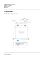
9.1 Mechanical specification............................................................................................................
........88
GAMIC Proprietary
Code: ENIGMA III User Manual
Edition: 1 Revision: 4
Date: 19/12/2008
Page: 6/97
9.2 Electrical specification....................................................................................................
...................89
9.2.1 Input voltage.................................................................................................................
..............89
9.2.2 Input Downlink.....................................................................................................................
......89
9.2.3 Output Uplink................................................................................................................
.............89
9.2.4 Output Trigger.....................................................................................................
.......................89
9.2.5 Input Azimuth TAG parallel.............................................................................................
..........89
9.2.6 Input Elevation TAG parallel...............................................................................
......................90
9.2.7 Input TAGS serial RS422................................................................................................
...........90
9.3 Environmental requirements............................................................................................
..................90
Technical specification - Single Polarization..................................................................................
........91
9.3.1 ENIGMA III IF DIGITIZER (IFD)............................................................................................
91
9.3.2 ENIGMA III Host...............................................................................................................
........92
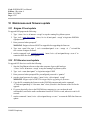
10 Maintenance and firmware update..................................................................................................
.........95
10.1 Enigma III host update...................................................................................................
..................95
10.2 PCI-Receiver card update.................................................................................................................
95
10.3 Antenna alignment........................................................................................................................
....96
10.4 Setting prf limits...................................................................................................................
............96
10.5 IQ Recording................................................................................................................
....................97
GAMIC Proprietary
Code: ENIGMA III User Manual
Edition: 1 Revision: 4
Date: 19/12/2008
Page: 7/97
Illustration Index
Illustration 1: Spectrum showing clutter and weather...................................................................
...............14
Illustration 2: Time domain filtered spectrum.......................................................................
.......................14
Illustration 3: Frequency domain filtered spectrum......................................................................................
14
Illustration 4: PPI-V pulse Pair Processing...............................................................................................
....15
Illustration 5: PPI-Z Pulse Pair Processing...........................................................................................
........15
Illustration 6: PPI-V DFT Processing........................................................................................
...................15
Illustration 7: PPI-Z DFT Processing...........................................................................................................
.15
Illustration 8: PPI showing clutter power measured by frequency domain filtering...................................16
Illustration 9: PPI showing clutter power measured by time domain filtering............................................16
Illustration 10: SQI A-Scope..............................................................................................................
...........17
Illustration 11: Speckle remover................................................................................................
...................19
Illustration 12: Time and range averaging.................................................................................
...................20
Illustration 13: Typical spectrum showing weather and clutter targets........................................................21
Illustration 14: 40 dB IIR clutter filter...............................................................................................
...........22
Illustration 15: 50 dB IIR clutter filter...............................................................................................
...........22
Illustration 16: IIR time domain clutter filter........................................................................
.......................22
Illustration 17: DC cancelation...............................................................................................
......................23
Illustration 18: Spectrum interpolation........................................................................................
.................23
Illustration 19: DFT processing.........................................................................................
...........................27
Illustration 20: FFT processing...................................................................................................
..................28
Illustration 21: Range doppler dilemma.............................................................................
..........................29
Illustration 22: Radar equation................................................................................................................
......30
Illustration 23: Definition of radar losses...............................................................................
......................31
Illustration 24: Dynamic angle syncing.......................................................................................
.................31
Illustration 25: Integrated pulses versus PRF and scanrate..........................................................................32
Illustration 26: Dual PRF unfolding.................................................................................
............................33
Illustration 27: ENIGMA III 19" enclosure..................................................................................
................88
GAMIC Proprietary
Code: ENIGMA III User Manual
Edition: 1 Revision: 4
Date: 19/12/2008
Page: 8/97
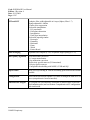
EDITION
REVISION
DATE
Modification Object
1
0
22/11/2007
First Edition by mt
1
1
20/06/2008
vk
- Added DualPolMode, AFCSettings,
thresholdFlagsTable, ZeroFilter,
gasAttenuation
- Added: noisesample, sampleburst,
setafcmode
- Ray data format
1
2
06/10/2008
mt
–
–
1
3
09/10/2008
Minor text revisions
Added trigger, coho, sector blanking
and extended dynamic range parameter
mt
New error code
1
4
19/12/2008
ss
SDP Status in ray format has – amount of
free memory instead of memory usage
GAMIC Proprietary
Code: ENIGMA III User Manual
Edition: 1 Revision: 4
Date: 19/12/2008
Page: 9/97
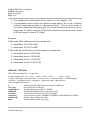
1 Introduction
History of GAMIC SDP Processors
1995 GSP01
PC Card for non Doppler Low-Cost Applications
1996 GSP02
Stand alone Doppler Signal Processor
1997 ENIGMA I
First generation of high performance video baseband Doppler Processor. Up to 2
MAIN boards (3 DSP's) and 3 Expansion boards (8 DSP's) each
1998 ENIGMA II High performance Digital IF Doppler Signal Processor Receiver. Up to 2 MAIN
boards (6 DSP's) and 3 Expansion boards (8 DSP's) each.
2003 ENIGMA III High Performance FPGA / Linux host based dual polarization IF Doppler Signal
Receiver. Signal processor algorithm run on a LINUX based host computer.
The ENIGMA III Signal Processor consists of two main modules. The IF-Digitizer (IFD) and the Signal
Processor host computer. The host computer is basically a Linux based standard inidustrial PC. ENIGMA
III performs two main tasks:
●
Digital Receiver Functions to obtain I, Q and Burst Pulse statistics. This processing is done on the
IFD and includes matched-filtering and extraction of dynamic "I" and "Q" values. In addition,
burst pulse is analyzed with respect to frequency, phase and amplitude to provide digital phase
locking, AFC and advanced processing and control features not present in traditional radar's.
●
Weather Information extraction to obtain Intensity, Velocity and spectral width and dual
polarization moments like ZDR, LDR, KDP, PHIDP and RHOHV. This operation include Doppler
and Intensity processing to extract the calibrated reflectivity, the mean velocity and spectrum
width. Clutter filtering by Doppler filtering in the time- or frequency- domain, thresholding and
velocity unfolding by dual PRF.
The IF Digitizer Module is housed in a sealed box. The main purpose is to digitize the analog IF signals
with a minimum of additional computational effort. The fiber optic link ensures the galvanic isolation of
the IF Digitizer Module from the rest of the digital components, thus avoiding additional ground loops
and other stray effects. Note, that the "Uplink" serial coaxial cable is isolated as well from the IF
Digitizer Module. Due to this technique, distances up to 100 meters between the IF Digitizer module and
the signalprocessor can be realized.
GAMIC Proprietary
Code: ENIGMA III User Manual
Edition: 1 Revision: 4
Date: 19/12/2008
Page: 10/97
2 Algorithms
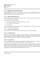
2.1 Thresholding
As the radar signal is contaminated with noise it is important to apply thresholding to the radar data.
Thresholding means that bins that pass one or the combination of several tests are discarded and flagged
as invalid. A combination of the following thresholds can be applied to all physical moments. The
combination of the flags is stored in a binary bit mask.
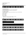
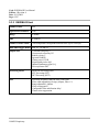
Parameter: thresholdFlagsTable
Remark:
The value for the threshold flags can be calculated with the Tool
EnigmaThresholdFlagCalculator
Threshold combination
Value
All Pass
FFFF
All Fail
0000
SQI
3333
SQI | NOISE
0033
SQI | CCOR
1111
SQI & CCOR
7777
SQI | NOISE | CCOR
0011
CCOR
5555
CCOR | NOISE
0055
NOISE
00FF
RHOHV
0F0F
RHOHV | SQI
0303
RHOHV & SQI
3F3F
RHOHV | NOISE
000F
Table 1: Useful threshold flag combinations
GAMIC Proprietary
Code: ENIGMA III User Manual
Edition: 1 Revision: 4
Date: 19/12/2008
Page: 11/97
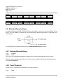
2.1.1 Noise Power threshold
The Noise Power threshold [dB] is related to the noise floor measured through noise sampling and is
applied to reflectivity data. Typically, the noise threshold is 1 dB above the noise floor.
Parameter: NOISEThreshold
2.1.2 CCOR threshold
The clutter power threshold [dB] is compared to the clutter power, obtained from the 4. order Chebyshev
IIR high pass filter or the filtered result from the frequency domain filtering. Reflectivity data and/or
radial velocity and/or spectral width data can be thresholded, when the calculated clutter power exceeds
the clutter threshold limit.
Parameter: CCORThreshold
2.1.3 SQI threshold
The Signal quality threshold (SQI) is compared to the signal quality, resulting from autocorrelation
processing. A signal quality value of 0 represents only noise, whereas a value of 1 represents a perfect
tone (sine wave). This threshold is absolute for thresholding of Doppler moments (radial velocity and
spectral width). Typically values for thresholding are 0.4..0.5, depending on receiver input S/N ratio.
Parameter: SQIThreshold
2.1.4 RHOHV Threshold
In SIDPOL configuration the RhoHV moment can be used for thresholding. RhoHV is close to 1 for
spherical targets (water droplets) and quickly falls to lower values for other targets. A good starting value
would be 0.7-0.8
Parameter: RHOHVThreshold
2.1.5 PhiDP SNR Threshold
In SIDPOL configuration the PhiDP and the related KDP moment can be thresholded with SNR. If the
SNR of the signal is lower than the specified threshold the PhiDP and KDP moments will be thresholded.
Set threshold to 0 to disable this thresholding algorithm.
Parameter: PhidpSNR
GAMIC Proprietary
Code: ENIGMA III User Manual
Edition: 1 Revision: 4
Date: 19/12/2008
Page: 12/97
2.1.6 Adjusting reflectivity thresholds
Uncorrected reflectivity data (UZ) is not corrected for clutter. In order to compare the influence of
threshold adjustments for corrected reflectivity data (CZ), open two A-Scopes or PPI's. One for
uncorrected reflectivity and one for corrected reflectivity.
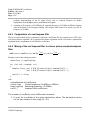
2.1.6.1 NOISE Threshold Parameter
This threshold [dB] rejects corrected reflectivity data, which is n dB above the noise floor. The noise
floor was obtained from noise sampling.
In the Extended parameter dialog in FrogRT
●
Set the noise threshold (Typically the threshold is set to 0.5..2 dB)
●
Select NOISE for CZ threshold flags
●
Click on Apply
Observe the two displays for UZ and CZ data. The CZ data should present a „clean“ picture without
noise. Fine-tune the noise threshold setting.
2.1.6.2 Clutter threshold Parameter
Two parameters in the extended SDP settings are related to clutter processing and thresholding:
2.1.6.2.1 CCOR Threshold:
The CCOR threshold is selectable from 0 dB .. -90 dB. The clutter power is obtained from the 4th.order
clutter filter or from the frequency domain processing. If the clutter power is less than the CCOR
threshold, reflectivity data may be thresholded (=rejected), if the appropriate CZ threshold flag CCOR is
enabled (CCOR is always negative as it is the Clutter Correction value in dB).
2.1.6.2.2 IQ clutter filter
The 4th. order high pass clutter filter can be configured to have different cutoff frequencies. All filters
have a stop band attenuation of 40 dB (or 50 dB depending on the selected filter set).
Allpass filter means no filtering. It does not remove any clutter. Filter IQ1 has the lowest cutoff
frequency, filter IQ7 has the highest cutoff frequency. Filter IQ1 is the „smoothest“ filter type, which will
probably reject little clutter, whereas filter type IQ7 will remove most of the clutter. Unfortunately,
weather and clutter spectra overlap, so it is important to select a clutter filter, which offers a good
compromise. From experience, IQ2..IQ4 should be selected for a first step.
GAMIC Proprietary
Code: ENIGMA III User Manual
Edition: 1 Revision: 4
Date: 19/12/2008
Page: 13/97
When using the frequency domain filtering (FFT and DFT mode) Interpolation or Dual Slope
Interpolation should be used. These filters do not affect weather targets overlapped by clutter
●
Set CCOR threshold to –30 dB.
●
Select Clutter Micro Suppression Threshold (30-40dB) if you are using range sampling
●
Select IQ clutter filter to IQ3.
●
Select NOISE | CCOR for CZ threshold flags.
●
Click on Apply in the extended SDP settings.
With this parameter settings, clutter will be thresholded (= rejected), when the calculated clutter power is
less than the CCOR threshold level otherwise the measured clutter power is subtracted from the echo. If
you can identify a strong clutter target in the closer area of the radar, observe the difference in the
uncorrected and corrected reflectivity A-Scope.
The results when using Pulse Pair Processing (PPP) or one of the frequency domain processing modes
(FFT or DFT)will be different. The main difference is that the time domain filtering used by PPP is not
adaptive. It will always subtract the power measured at zero velocity. Regardless if there is clutter
present. As an side effect weather at zero (radial-) velocity will also be attenuated. The clutter filter used
by the frequency domain processing modes are adaptive. The filter will adapt to the spectrum (both in
attenuation and width).
Remark:
As the frequency domain filters (Interpolation and Dual Slope Interpolation) adapt to the
signal it is not necessary to keep them as small as possible (As would be necessary with the
classical time domain filtering). IQ5 is a good starting value for frequency domain
processing.
Remark:
The clutter filter for Pulse Pair Processing should be as small as possible and should be
switched off for higher (clutter free) elevations. A good value for time domain filtering
would be IQ3.
Parameter: ClutterFilter and MaxFilterRange
GAMIC Proprietary
Code: ENIGMA III User Manual
Edition: 1 Revision: 4
Date: 19/12/2008
Page: 14/97
2.1.6.3 Clutter filtering examples
Consider the following
example. The spectrum
shows the combination of
a strong clutter target and
weather.
Illustration 1: Spectrum showing clutter and weather
The
same
weather
situation with time domain
clutter filter applied. The
clutter peak is attenuated
by 40dB but still is ~40dB
above noise. The weather
echo around zero velocity
also
was
strongly
attenuated.
Illustration 2: Time domain filtered spectrum
The same situation again,
but now filtered by
spectrum
interpolation.
The clutter peak has been
completely removed and
the weather echo stayed
intact.
Illustration 3: Frequency domain filtered spectrum
GAMIC Proprietary
Code: ENIGMA III User Manual
Edition: 1 Revision: 4
Date: 19/12/2008
Page: 15/97
Illustration 5: PPI-Z Pulse Pair
Processing
Illustration 4: PPI-V pulse Pair
Processing
In the above shown examples the clutter has been removed by time domain filtering. They show strong
attenuation in the weather at zero velocities.
Illustration 7: PPI-Z DFT Processing
Illustration 6: PPI-V DFT Processing
The same weather situation using frequency domain filtering. The difference and the advantage of
frequency domain filtering in respect to time domain filtering is quite obvious.
GAMIC Proprietary
Code: ENIGMA III User Manual
Edition: 1 Revision: 4
Date: 19/12/2008
Page: 16/97
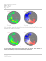
The ENIGMA III signal processor has the capability to output CCOR as moment. The two following
images show the CCOR moment (Clutter Power) recorded with different clutter filter algorithms.
Illustration 9: PPI showing clutter power
measured by time domain filtering
Illustration 8: PPI showing clutter power
measured by frequency domain filtering
The above shown examples are actual screenshots from the FrogRT maintenance display showing a
weather situation recorded in June 2007 in Germany. Data courtesy Deutscher Wetterdienst (DWD)
GAMIC Proprietary
Code: ENIGMA III User Manual
Edition: 1 Revision: 4
Date: 19/12/2008
Page: 17/97
2.1.7 Adjusting velocity thresholds
Open an A-Scope or a PPI for radial velocity (V) and observe the effects of the following parameter.
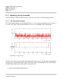
2.1.7.1 SQI Threshold Parameter
The SQI threshold parameter can be adjusted from 0 to 1. 0 is a signal, containing only noise, whereas 1
is a „pure“ tone signal. Typically this threshold is set to 0.4..0.5, depending on the signal quality.
Illustration 10: SQI A-Scope
The figure above shows the calculated signal quality index SQI over time. The data where acquired from
a radar receiver I/Q baseband output (only noise). When setting a SQI threshold of 0.5 and enabling V
threshold flag for SQI, most velocity speckles will be removed.
●
Select 0.0 for SQI threshold parameter.
GAMIC Proprietary
Code: ENIGMA III User Manual
Edition: 1 Revision: 4
Date: 19/12/2008
Page: 18/97
●
Select SQI for V threshold flags.
●
Select IQ clutter All pass.
●
Click on Apply.
●
Now, you will see a very noisy A-Scope for the radial velocity.
Increase the SQI threshold to 0.4.
The noise in the A-Scope almost disappears. Fine-tune the SQI parameter, until the noise is almost
removed completely.
2.1.7.2 Clutter threshold Parameter
Only the CCOR clutter threshold and the IQ clutter filter configuration is relevant for rejecting zero
velocity (clutter).
See description for CCOR threshold and IQ clutter filter above.
●
Set CCOR threshold to –30dB.
●
Select IQ clutter filter to All pass.
●
Select SQI | CCOR for V threshold flags.
●
Click on Apply in the extended SDP settings.
If you can identify a strong clutter target in the closer area of the radar, the radial velocity in the A-Scope
indicates a value around zero (= clutter).
●
Select IQ clutter filter IQ3.
●
Click on Apply in the extended SDP settings.
If you can identify a strong clutter target in the closer area of the radar, the radial velocity in the A-Scope
will be thresholded (= rejected).
GAMIC Proprietary
Code: ENIGMA III User Manual
Edition: 1 Revision: 4
Date: 19/12/2008
Page: 19/97
2.1.8 Adjusting spectral width thresholds
The thresholding of spectral width data is the same as for radial velocity. See description above.
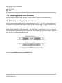
2.2 Reflectivity and Doppler speckle remover
Speckle removers can be applied to all final physical moments (Z, UZ, V, W). They can be switched on or
off separately for reflectivity and Doppler results. Speckle removers identify isolated valid bins in the
output data ray. In that case, they are removed and flagged as unvalid ( or thresholded).
The speckle remover removes isolated valid data range bins, whose neighbors have been thresholded
before (NOISE threshold, CCOR threshold...). The reflectivity speckle remover can be applied to
corrected and uncorrected reflectivity data (Z and UZ). The Doppler speckle remover can be applied to
radial velocity (V) and spectral width data (W).
Illustration 11: Speckle remover
Parameters:SpeckleRemoverZ and SpeckleRemoverV
GAMIC Proprietary
Code: ENIGMA III User Manual
Edition: 1 Revision: 4
Date: 19/12/2008
Page: 20/97
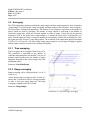
2.3 Averaging
The SDP configuration parameter include the range sample and time sample parameter. Note, sometimes
“range sample” is also referred to “range averaging” and time sample is also referred to “time averaging”.
The figure below explains both parameters. The number of time samples is equivalent to the number of
pulses, which are used for averaging. The number of range samples is equivalent to the number of
consecutive range bins, which are averaged together in order to output 1 range bin for the physical
moments Z,V,W. In the figure below, range sample is 5, assume the range step is configured for 125
meter. First the signal processor averages the number of time samples (=pulses) for each range bin. Then,
the signal processor averages 5 range bins together. The resolution of the output data (physical moments
Z,V,W) is (5-1)x125 meter = 500 meter. When setting range sample to zero, no range averaging is applied
and the output resolution is equal to the configured rangestep.
2.3.1 Time averaging
Time averaging can be configured from 8 up to 256.
This parameter is equivalent to the number of
coherently integrated pulses for the AKF’s. In case of
dynamic angle syncing mode, the number of pulses
integrated, depends on the selected angle step, PRF
and antenna speed.
Parameter: SyncModeParam
2.3.2 Range averaging
Range averaging can be configured from 1 to 40. A
value of 1:q
means, that no range averaging is done. A value of 2
means, that 2 consecutive bins are averaged together
in order to form one output range bin. The range
averaging is applied on the AKF’s result.
Parameter: RangeSample
Illustration 12: Time and range averaging
GAMIC Proprietary
Code: ENIGMA III User Manual
Edition: 1 Revision: 4
Date: 19/12/2008
Page: 21/97
2.4 Doppler clutter filters
Doppler clutter filtering is based on the valid assumption that stationary ground targets appear as strong
narrow peaks around zero in the spectrum (sampled over the PRT).
Illustration 13: Typical spectrum showing weather and clutter targets
The doppler clutter filter (both time- and frequency- domain processing) attenuate the radar signal around
the zero frequencies. Time domain processing applies a configurable highpass filter to the radar data. This
attenuates all DC components in the signal, regardless if they are due to clutter or weather. The frequency
domain filter work on the above mentioned assumption and are able to separate weather and clutter
targets.
2.4.1 Time domain filtering
The pulse-pair processing performs as a first stage filtering of the input data. It has an implementation of
the digital infinite impulse response (IIR) filters. There are seven 40 dB and seven 50 dB 4-order
Chebyshev highpass filters. The coefficients can be chosen with the parameter 'ClutterFilter'.
0 and 8
– no filtering;
from 1 to 7
– one of 40 dB filter;
from 9 to 15 – one of 50 dB filter.
Additional parameter are ZeroFilter and FilterDelay. When using PRF staggering it is recommended to
use the ZeroFilter and FilterDelay parameter as consecutive rays are sampled with a different sampling
frequency (PRF). The recursive filters must be reset to avoid artifacts.
GAMIC Proprietary
Code: ENIGMA III User Manual
Edition: 1 Revision: 4
Date: 19/12/2008
Page: 22/97
Illustration 14: 40 dB IIR clutter filter
Illustration 15: 50 dB IIR clutter filter
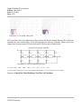
The figure below shows the digital clutter filter structure for the time domain filtering. The coefficients
determine the filter characteristics. Seven different high pass filter are selectable. Please refer to the
chapter Pulse Pair processing, DFT processing and FFT processing for further details.
Illustration 16: IIR time domain clutter filter
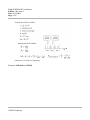
A'n = B0An + B1An-1 + B2An-2 + B3An-3 + B4An-4 – C1A'n-1 – C2A'n-2 – C3A'n-3 – C4A'n-4
An are the unfiltered samples, A'n are the filtered samples, B0-B4 and C1-C4 are the coefficients of the IIR filter
Parameter: ClutterFilter, MaxFilterRange, ZeroFilter and FilterDelay
GAMIC Proprietary
Code: ENIGMA III User Manual
Edition: 1 Revision: 4
Date: 19/12/2008
Page: 23/97
2.4.2 Frequency domain filtering
For frequency domain filtering several different algorithms have been implemented the algorithm can be
chosen with the parameter InterpolationMode.
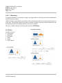
2.4.2.1 DC Cancelation
This is the simplest frequency domain filter. It is basically a highpass filter
(like the timedomain IIR filter) with infinite stopband attenuation.
According to the specified filter width the taps around frequency 0 are
zeroed. The filter is not adaptive and might introduce ringing (Gibbs
Phenomenon)
2.4.2.2 Half plane subtraction
Half plane (Passarelli et al 1981) subtraction removes symetric
components around zero from the spectrum. This includes the symetric
clutter peaks and sidelobes and unfortunately weather echoes with zero
radial velocity. This filter is adaptive.
Illustration 17: DC
cancelation
2.4.2.3 Interpolation
Beginning at frequency zero the minimum is searched (in both directions)
up to a maximum width (see filter number). The center pixels are
discarded and replaced by a linear interpolation. This filter is adaptive.
2.4.2.4 Dual slope search interpolation
This filter works similar to the interpolation above. The difference is that it
tries to interpolate across the first sidelobe (introduced by the strong clutter
target). This filter is adaptive.
Illustration 18: Spectrum
interpolation
GAMIC Proprietary
Code: ENIGMA III User Manual
Edition: 1 Revision: 4
Date: 19/12/2008
Page: 24/97
2.4.2.1 Windowing
To suppress sidelobes it is necessary to apply a tapering window to the data prior to the transformation
into the frequency domain.
Window functions generally have a maximum value centered on the time series and are tapered near zero
at the ends. This tapering reduces the spectrum smearing a leakage of spectral energy introduced by the
discontinuity imposed by sampling when the end points are joined.
The type of window function is chosen by the parameter FFTWindow.
FFTWindow
Possible values are:
0 – Rectangular
1 – Hamming
2 – Blackman
3 – Hann
4 – Welch
5 – Kaiser-Bessel
GAMIC Proprietary
Code: ENIGMA III User Manual
Edition: 1 Revision: 4
Date: 19/12/2008
Page: 25/97
Terminology:
•
•
•
•
N represents the width, in samples, of a discrete-time window function. Typically it is an integer
power-of-2, such as 210 = 1024.
n is an integer, with values 0<=n<=N-1. So these are the time-shifted forms of the windows:
w(n)=w 0(n-(N-1)/2) , where w(n) is maximum at n=0.
Some of these forms have an overall width of N−1, which makes them zero-valued at n=0 and
n=N−1. That sacrifices two data samples forno apparent gain, if the DFT size is N. When that
happens, an alternative approach is to replace N−1 with N in the formula.
Each figure label includes the corresponding noise equivalent bandwidth metric (B), in units of
DFT bins. As a guideline, windows are divided into two groups on the basis of B. One group
comprises 1<=B<=1.8 , and the other group comprisesB>=1.98 . The Gauss and Kaiser windows
are families that span both groups, though only one or two examples of each are shown.
Parameter: ClutterFilter, MaxFilterRange, FFTWindow and InterpolationMode
GAMIC Proprietary
Code: ENIGMA III User Manual
Edition: 1 Revision: 4
Date: 19/12/2008
Page: 26/97
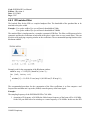
2.5 Pulse-pair processing.
The basis for time domain moment estimation is the transform relationship of the autocorrelation function
of the complex signal to the power spectrum.
The estimate of the autocorrelation can be calculated from the complex input time series at the given
range as following:
T 0=
1
N
N −1
∑ s*k s k
k=0
1
R m=
N −m
N −m −1
∑
k=0
s 'k* s 'k
Where:
M
number of pulses for averaging
sk
represents unfiltered I and Q samples
s'k
represents filtered I and Q samples
*
complex conjugation
g
system gain
S
signal power
C
clutter power and N is a noise power.
T0
unfiltered signal power = g(S+C)+N
R0
filtered signal power = gS+N
R1
first lag of a filtered signal power =g S exp[j π V'-π2 W2/2]
R2
second lag of a filtered signal power = g S exp[j 2π V'-2π2W2]
It is well known that the first few lags of the autocorrelation function are sufficient to find a Doppler
velocity and spectrum width. So, it is enough to calculate T0 , R0, R1, R2.
V' is the mean velocity in the sampling volume and W is the mean spectrum width. Radial velocity in the
normalized Nyquist interval from -1 to 1 and spectrum width in the normalized Nyquist interval [0,1].
Parameter: AcfMode
GAMIC Proprietary
Code: ENIGMA III User Manual
Edition: 1 Revision: 4
Date: 19/12/2008
Page: 27/97
2.6 DFT processing.
The Doppler power spectrum may be estimated from the Discrete Fourier Transform (DFT) of the
complex signal.The DFT decomposes the observed data into a sum of sinusoids having amplitude and
phase that will exactly reproduce the observed data. These N discrete components are adequate to
reconstruct the entire continuous spectrum as long as the complex data samples are taken at a rate equal
to or greater than the bandwidth of a signal (Which is typically 500kHz - 2MHz).
The autocorrelations are calculated using the Wiener–Khinchin theorem, which relates the autocorrelation
function to the power spectral density via the Fourier transform:
The advantage of measuring the full Doppler spectrum is that spectral impurities, such as ground clutter,
can be easily suppressed by algorithms. When highly coherent spectral components (e.g., clutter) are
present, the correlation usually will not decay to zero within N samples.
Processing stages of the DFT algorithm:
1) applying window function
on the input data;
2) forward DFT;
3) filtering;
4) inverse DFT, which produces
autocorrelations.
Parameter: AcfMode
Illustration 19: DFT processing
GAMIC Proprietary
Code: ENIGMA III User Manual
Edition: 1 Revision: 4
Date: 19/12/2008
Page: 28/97
2.7 FFT processing.
The above described DFT (Discrete Fourier Transform)
processing needs a lot of CPU resources. In case the DFT
processing can't manage the acquired data, some optimizations
can be used. DFT works on the number of samples being a
power of 2 faster than on an arbitrary number of samples. This
optimization is called FFT (Fast Fourier Transform)
The data is split into two overlapping groups, both groups
have a 'power of 2' number of samples. Previously described
DFT (now FFT) performed on both groups and then results are
averaged.
If the number of samples is exactly a power of 2, then no
splitting is needed.
Parameter: AcfMode
Illustration 20: FFT processing
GAMIC Proprietary
Code: ENIGMA III User Manual
Edition: 1 Revision: 4
Date: 19/12/2008
Page: 29/97
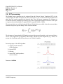
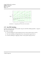
2.8 Range-Doppler Dilemma
The physical relationship between the unambiguous range and unambiguous velocity limits the dynamics
of the acquired data. An example is shown in the diagram below. The unambiguous velocity can be
increased with the staggered PRF algorithm. The unambiguous range can be increased by reducing the
PRF (This also reduces the unambiguous velocity)
Illustration 21: Range doppler dilemma
GAMIC Proprietary
Code: ENIGMA III User Manual
Edition: 1 Revision: 4
Date: 19/12/2008
Page: 30/97
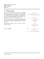
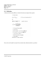
2.9 Calibration
Calibrated reflectivity data [dBZ] are calculated from the meteorological radar equation.
Illustration 22: Radar equation
Please refer to the FrogRT user manual for more details about calibration and how to perform it.
GAMIC Proprietary
Code: ENIGMA III User Manual
Edition: 1 Revision: 4
Date: 19/12/2008
Page: 31/97
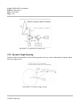
Illustration 23: Definition of radar losses
2.10 Dynamic Angle Syncing
Dynamic angle syncing mode is used for data acquisition. One ray consist of the number of pulses which
fall in one angle sector.
Illustration 24: Dynamic angle syncing
GAMIC Proprietary
Code: ENIGMA III User Manual
Edition: 1 Revision: 4
Date: 19/12/2008
Page: 32/97
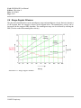
Illustration 25: Integrated pulses versus PRF and scanrate
2.11 Dual PRF Unfolding
In order to increase the mean velocity dynamic range, the dual PRF unfolding algorithm (= staggered
PRF ) has been implemented.
Three modes are available:
●
Two times unfolding (2/3 stagger staggering; increases velocity dynamic range by factor 2)
●
Three times unfolding (3/4 staggering; increases velocity dynamic range by factor 3)
●
Four times unfolding (4/5 staggering; increases velocity dynamic range by factor 4)
GAMIC Proprietary
Code: ENIGMA III User Manual
Edition: 1 Revision: 4
Date: 19/12/2008
Page: 33/97
Illustration 26: Dual PRF unfolding
Parameter: PrfLimits and PrfTab
GAMIC Proprietary
Code: ENIGMA III User Manual
Edition: 1 Revision: 4
Date: 19/12/2008
Page: 34/97
2.12 Default values for the extended SDP parameter
Default values for the extended parameters can be obtained from the table below, but keep in mind, that
optimal values can only be obtained by adjusting each parameter according to the specific requirements.
Each site needs different parameter for optimum performance.
Clutter Micro Suppression
On
Only when RangeSampling is selected
Clutter MicroSuppression Threshold 30 dB
Reflectivity Speckle Filter
On
Velocity Speckle Filter
On
Zero Filter
Off (Single PRF)
For Pulse Pair Processing
On (PRF staggering)
Filter Stabilization Delay
>4
NOISE Threshold
1 dB
SQI Threshold
0.4
CCOR Threshold
-40 dB
IQ Clutter Filter
IQ 3
Z Threshold Flags
NOISE | CCOR
V Threshold Flags
SQI | CCOR
W Threshold Flags
SQI | CCOR
UZ Threshold Flags
NOISE
Gas attenuation
0.016 dB/km
GAMIC Proprietary
For Pulse Pair Processing
DFT or FFT processing IQ5
For C-Band
Code: ENIGMA III User Manual
Edition: 1 Revision: 4
Date: 19/12/2008
Page: 35/97
3 Network
Network is configured in the file /etc/conf.d/net. The file looks as follows. Here a static IP address or
DHCP can be configured. Just comment out the corresponding lines.
/etc/conf.d/net:
# To avoid delay on booting, use the fixed address configuration
# and comment out the dhcp/fallback part
# Static IP address
#config_eth0=( "192.168.3.11 netmask 255.255.255.0" )
#route_eth0=( "default via 192.168.3.254" )
# DHCP configuration config_eth0=( "dhcp" )
dhcpcd_eth0="t 10 L"
#fallback_eth0=( "192.168.3.11 255.255.255.0" )
#fallback_route_eth0=( "default via 192.168.3.1" )
In case of problems the ENIGMA host PC can be booted into single user mode. Connect a keyboard and
a monitor (or s serial terminal) to the ENIGMA PC and enter softlevel=single in the GRUB boot
menu.
4 SDP settings
SDP settings are stored in the file /opt/enigma3/controlagent.is
All SDP parameters are saved at the exit and restored automatically on start.
This file contains list of 'set' commands to set all the parameters to specified values.
At run-time settings can be saved and loaded with corresponding 'save' and 'load' command. They don't
have arguments.
See 'Parametrization' section for detailed syntax.
5 SDP interfaces
SDP has two network TCP interfaces:
1) command interface – for control and parametrization.
2) acquisition interface – to receive the acquired rays.
GAMIC Proprietary
Code: ENIGMA III User Manual
Edition: 1 Revision: 4
Date: 19/12/2008
Page: 36/97
5.1 Command interface
SDP is controlled by text commands via network session. Network session has a following steps:
1) connection
2) authorization
3) parametrization
4) acquisition
GAMIC Proprietary
Code: ENIGMA III User Manual
Edition: 1 Revision: 4
Date: 19/12/2008
Page: 37/97
5.1.1 Connection
5.1.1.1 Browser interface
Most of the parameters described in the following section also can be accessed through a comprehensive
HTTP interface. Just point your browser at the IP address of the ENIGMA3 signal processor giving the
port number 30000
Example: http://enigma3.gamic.com:30000
5.1.1.2 Telnet
SDP listens on TCP port 5555. Frog-Muran software connects as a TCP client to this port. For test and
maintainance purposes 'telnet' client can be used.
Connect to 'enigma3' host as following:
telnet enigma3 5555
5.1.1.3 Authorization
When the command conenction is established, SDP provides its information:
auth ControlAgent
The command for authorization is 'auth <ClientType>'
SDP authorizes two types of clients.
1) Controller.
2) Secondary.
'Controller' means, that SDP binds acquisition and command interface in one logical session. If command
interface is closed by the client, SDP closes the acquisition connection. It is designed for use in FrogMuran software. It is important to have only one Controller connection at a time!
'Secondary' doesn't have this restriction. It is used for tests and maintenance.
Example:
auth Controller
GAMIC Proprietary
Code: ENIGMA III User Manual
Edition: 1 Revision: 4
Date: 19/12/2008
Page: 38/97
6 Parametrization
There are many commands and parameters supported by the SDP.
The list of commands and parameters with short descriptions can be obtained through the 'help'
command:
help
SDP responds with a text similar to the shown below::
Format: help [<command_name> | <param_name>]
Where command_name is:
get: get parameter
getadcdiff: get phase and power difference for hi/lo channels
getafcstatus: Get AFC status
getasciistatus: Request status from IFD and PCI receiver
getburst: get burst parameters
getconverter: converter status
geterrorconditions: Get error conditions
getifsampling: Get IF Sampling Parameters
getpower: power status
gettemperature: temperature
getversion: get hardware version numbers
load: load parameters
noisesample: Noise sampling
sampleburst: get burst samples
save: testsave parameters
set: set parameter
setafcmode: Set AFC Mode
setpulsewidth: Set Pulse Width Index
settxdtrigger: Set TxD trigger
startacq: start acquisition
stopacq: stop acquisition
param_name is:
AFCSettings: AFC settings
AcfMode: ACF mode
AzimuthAbsoluteOffset: calibratiobn offset for antenna alignment
AzimuthSynchroOffset: calibratiobn offset for encoder/synchro diference
BurstTiming0: burst sample timing
BurstTiming1: burst sample timing
BurstTiming2: burst sample timing
BurstTiming3: burst sample timing
CCORThreshold: CCOR threshold
ClutterFilter: Clutter filter number
ClutterMicroSuppression: Set clutter micro suppression
ClutterMicroSuppressionThreshold: Clutter micro suppression threshold
GAMIC Proprietary
Code: ENIGMA III User Manual
Edition: 1 Revision: 4
Date: 19/12/2008
Page: 39/97
DataFormat: Frog output data format type
DualPolMode: dual polarization mode
ElevationAbsoluteOffset: calibratiobn offset for antenna alignment
ElevationSynchroOffset: calibratiobn offset for encoder/synchro diference
FFTWindow: Type of smoothing window for FFT and DFT ACF algorithms
FIRCoeff0: FIR coefficients for pulse 0
FIRCoeff1: FIR coefficients for pulse 1
FIRCoeff2: FIR coefficients for pulse 2
FIRCoeff3: FIR coefficients for pulse 3
FilterDelay: IIR filter delay
HorVerSwitchDuration: Duration for MOHP Hor/Ver switching device in ms
IFDTagBaudRate: Baud rate IFD
InterpolationMode: FFT/DFT Interpolation method
LdrOffset: LDR offset
LongRaySize: If true, use 32bit raysize word
MaxFilterRange: Maximum filter range
NOISEThreshold: NOISE threshold
PCIRecTagBaudRate: Baud rate PCIREC
PRFTable: PRF table
PhidpOffset: PhiDP offset
PhidpSNR: Phidp SNR threshold
PrfLimits: PRF limits
PulseWidthIndex: PulseWidthIndex
RHOHVThreshold: RHOHV threshold
RainAttenuation: Rain attenuation correction
RainAttenuation_A: RainAttenuation_A
RainAttenuation_B: RainAttenuation_B
RainAttenuation_a: RainAttenuation_a
RainAttenuation_b: RainAttenuation_b
Range: Range for acquisition in km
RangeAdjust0: Range adjustment
RangeAdjust1: Range adjustment
RangeAdjust2: Range adjustment
RangeAdjust3: Range adjustment
RangeNorm: Range normalisation
RangeSample: Range samples
RangeStep: Range step in km.
RaySize: expected ray size
RecordName: file to save recorded raw data
RecorderMode: filenameRecorder mode
SDPType: SDP Type
SQIThreshold: SQI threshold
SectorblankingTable: Flags for 2D sectorblanking table
SectorblankingTableEnabled: Sector blanking on/off
SmoothDualPolParameter: Apply smoothing filter to KDP, RHOHV and ZDR
SpeckleRemover2D: 2D speckle remover
SpeckleRemoverV: Doppler speckle remover
GAMIC Proprietary
Code: ENIGMA III User Manual
Edition: 1 Revision: 4
Date: 19/12/2008
Page: 40/97
SpeckleRemoverZ: Reflectivity speckle remover
SyncModeParam: Sync mode
TagConfiguration: Serial TAGS configuration
Trig0Duration: Tigger 0 duration
Trig0Enable: Tigger 0 enable/disable
Trig0Invert: Tigger 0 invert
Trig0Start: Tigger 0 start
Trig1Duration: Tigger 1 duration
Trig1Enable: Tigger 1 enable/disable
Trig1Invert: Tigger 1 invert
Trig1Start: Tigger 1 start
UDPTagsHost: host that sends tags in UDP
UDPTagsPort: localhostport for UDP tags
ZdrOffset: ZDR offset
ZeroFilter: Clear IIR filter for every ray
dbz0: DBZ0
gasAttenuation: Gas Attenuation
noisePowerH: linear noise power horizontal
noisePowerV: linear noise power vertical
thresholdFlagsTable: Threshold flag table
To set a parameter type: set <param_name> <value>
To get a parameter type: get <param_name>
SDP responds:
get errormsg=null <Parameter>=<Value>
if successfull, or
get errormsg='<error text>'
if failed.
Commands start some actions.
General syntax is:
<Command> [<Arg>=<Value> ...]
SDP responds:
<Command> errormsg=null [<Arg>=<Value> ...]
if successful, or
<Command> errormsg='<error text>'
GAMIC Proprietary
Code: ENIGMA III User Manual
Edition: 1 Revision: 4
Date: 19/12/2008
Page: 41/97
if failed
6.1 Klystron related parameter
The following parameter can be configured for a Klystron system:
1) These parameter are only available if SDPType equals 13
2) After setting the parameters the command setpulsewidth has to be called (it will perform
the calculation of the burst coefficients and upload them to the COHO card)
3) The ENIGMA host PC must be equipped with the COHO card option.
6.1.1 KlystronGateDurationX
Duration of the gate signal in µs (0.2µs...50µs in 10ns increments). X represents the pulse width index
(0-3). After setting the parameters the command setpulsewidth has to be called (it will perform the
calculation of the burst coefficients and upload them to the COHO card)
Type:
Default:
Unit:
float
1
µs
6.1.2 KlystronGateStartX
Start of the gate signal (in respect to the burst start) in µs (-20µs...20µs in 10ns increments). X represents
the pulse width index (0-3). After setting the parameters the command setpulsewidth has to be called (it
will perform the calculation of the burst coefficients and upload them to the COHO card)
Type:
Default:
Unit:
float
0
µs
6.1.3 KlystronPulseDurationX
Length of the burst in µs (0.2µs...9.5µs in 10ns increments). X represents the pulse width index (0-3).
After setting the parameters the command setpulsewidth has to be called (it will perform the calculation
of the burst coefficients and upload them to the COHO card)
Type:
Default:
Unit:
float
1
µs
GAMIC Proprietary
Code: ENIGMA III User Manual
Edition: 1 Revision: 4
Date: 19/12/2008
Page: 42/97
6.1.4 KlystronTaperingStartX
Tapering percentage for the start of the burst (0...100% 100% means that the tapering is performed from
the start of the burst up to the middle of the burst). X represents the pulse width index (0-3). After
setting the parameters the command setpulsewidth has to be called (it will perform the calculation of the
burst coefficients and upload them to the COHO card)
Type:
Default:
Unit:
float
0
%
6.1.5 KlystronTaperingStopX
Tapering percentage for the end of the burst (0...100% 100% means that the tapering is performed from
the middle of the burst up to the end of the burst). X represents the pulse width index (0-3). After
setting the parameters the command setpulsewidth has to be called (it will perform the calculation of the
burst coefficients and upload them to the COHO card)
Type:
Default:
Unit:
float
0
%
6.1.6 KlystronWindowTypeStartX
Select taper function for start tapering (0: Linear, 1: Hamming, 2: Blackman). X represents the pulse
width index (0-3). After setting the parameters the command setpulsewidth has to be called (it will
perform the calculation of the burst coefficients and upload them to the COHO card)
Type:
Default:
int
0
6.1.7 KlystronWindowTypeStopX
Select taper function for stop tapering (0: Linear, 1: Hamming, 2: Blackman) X represents the pulse
width index (0-3). After setting the parameters the command setpulsewidth has to be called (it will
perform the calculation of the burst coefficients and upload them to the COHO card)
Type:
Default:
int
0
The following command sequence will configure pulse width 0 for a 1µs burst with a gate signal
GAMIC Proprietary
Code: ENIGMA III User Manual
Edition: 1 Revision: 4
Date: 19/12/2008
Page: 43/97
matching the burst exactly in time and 25% of linear tapering at both sides of the burst (25% tapering for
a burst duration of 1µs means tapering for 0.5µs * 0.25 = 0.125µs)
set KlystronGateDuration0 1
set KlystronGateStart0 0
set KlystronPulseDuration0 1
set KlystronTaperingStart0 25
set KlystronTaperingStop0 25
set KlystronWindowTypeStart0 0
set KlystronWindowTypeStop0 0
setpulsewidth 0
6.2 Trigger
The IFD module provides 2 additional configurable 5V @ 50Ω (15V optional) trigger. These trigger
signals have a configurable duration and the timing of the leading edge (in respect to the master trigger
from the PCI receiver card) can be configured too. The following parameter are used to configure the
triggers.
6.2.1 TrigXEnable
Enable/disable trigger x (e.g. Trig0Enable or Trig1Enable)
Type:
Default:
boolean
false
6.2.2 TrigXDuration
Duration of the trigger in µs (range 0...100µs). Resolution approx. 15ns
Type:
Default:
Unit:
float
1
µs
6.2.3 TrigXStart
Start of the leading edge in respect to the leading edge of the master trigger. (range -100...100 µs)
Type:
Default:
Unit:
float
0
µs
GAMIC Proprietary
Code: ENIGMA III User Manual
Edition: 1 Revision: 4
Date: 19/12/2008
Page: 44/97
6.2.4 TrigXInvert
Invert the trigger (When this trigger is disabled the output stays in a low state, regardles of the content of
this parameter.
Type:
Default:
boolean
false
6.3 Sector blanking
Sector blanking is configured through a azimuth versus elevation table providing a 1° resolution in
azimuth and a 0.5° resolution in elevation. The azimuth range is obviously 360° and the elevation range
is from -5° to 45°.
6.3.1 SectorblankingTable
Type:
Default:
table
empty table
The table is a bit mask coded in unsigned 32bit values. Per elevation step 360 values need to be coded.
This leads to 12 unsigned 32bit values (padded to 32bit) . The bits are ordered in clockwise azimuth
starting at 0° (MSB first). The full table has a length of 12x100 32bit values. The table starts at -5°
elevation.
Example:
The following table codes sector blanking in the range 10°-16° azimuth (one elevation step only)
Bits:
0000000000111111 1000000000000000 0000000000000000 0000000000000000 0000000000000000
0000000000000000 0000000000000000 0000000000000000 0000000000000000 0000000000000000
0000000000000000 0000000000000000
Values:
0x003f 0x8000 0x0000 0x0000 0x0000 0x0000 0x0000 0x0000 0x0000 0x0000 0x0000 0x0000
Remark:
The values have to be given as decimal number
(not in HEX as shown above)
GAMIC Proprietary
Code: ENIGMA III User Manual
Edition: 1 Revision: 4
Date: 19/12/2008
Page: 45/97
Example:
Configure sector blanking for a sector 10°-16° azimuth for elevation -5° to 3°.
set SectorblankingTable 63 32768 0 0 0 0 0 0 0 0 0 0 63 32768 0 0 0 0
0 0 0 0 0 0 63 32768 0 0 0 0 0 0 0 0 0 0 63 32768 0 0 0 0 0 0 0 0 0 0
63 32768 0 0 0 0 0 0 0 0 0 0 63 32768 0 0 0 0 0 0 0 0 0 0 63 32768 0 0
0 0 0 0 0 0 0 0 63 32768 0 0 0 0 0 0 0 0 0 0 63 32768 0 0 0 0 0 0 0 0
0 0 63 32768 0 0 0 0 0 0 0 0 0 0 63 32768 0 0 0 0 0 0 0 0 0 0 63 32768
0 0 0 0 0 0 0 0 0 0 63 32768 0 0 0 0 0 0 0 0 0 0 63 32768 0 0 0 0 0 0
0 0 0 0 63 32768 0 0 0 0 0 0 0 0 0 0 63 32768 0 0 0 0 0 0 0 0 0 0 63
32768 0 0 0 0 0 0 0 0 0 0
Remark:
Please note that only the elevation tables from -5° to 3° have been given. ENIGMA
automatically fills the table with 0's at the end.
6.3.2 SectorblankingEnabled
Type:
Default:
bool
false
With the parameter SectorblankingEnabled sector blanking can be enabled/disabled. Upload the table
once and use this parameter to toggle sector blanking.
6.4 Serial TAGS
As an option the ENIGMA signal processor can read the angle TAGS from a serial (RS422) line instead
of the 16bit parallel TAG lines. The serial interface has several configuration options.
6.4.1 PCIRecTagBaudRate
Specify the baudrate for the RS422 TAG input at the ENIGMA host. The baudrate can be specified
directly in baud (1200...4000000) and can also be a “non-standard” value like 500000 (500kbits/s).
Type:
Default:
Unit:
integer
9600
baud
GAMIC Proprietary
Code: ENIGMA III User Manual
Edition: 1 Revision: 4
Date: 19/12/2008
Page: 46/97
Remark: Only the baud rate is configurable. The other serial parameter are fixed. 1 stop bit. 1 start
bit and no parity will be used.
6.4.2 IFDTagBaudRate
Specify the baudrate for the RS422 TAG input at the ENIGMA IFD+. The ENIGMA IFD III+ provides
an additional input for the serial angle tags The baudrate can be specified directly in baud
(1200...4000000) and can also be a “non-standard” value like 500000 (500kbits/s).
Type:
Default:
Unit:
integer
9600
baud
Remark: Only the baud rate is configurable. The other serial parameter are fixed. 1 stop bit. 1 start
bit and no parity will be used.
6.4.3 TagConfiguration
With ENIGMA IFD III+ the input for the angle TAGS can be freely defined. The ENIGMA IFD III only
provides the option for angle TAGS at the host.
Type:
Default:
integer
0
Possible value:
0: Parallel tags at PCI Receiver card
1: Serial tags at PCI Receiver card
2: Serial tags at IFD (IFD+ only)
3: Azimuth at PCI Receiver card, Elevation at IFD (IFD+ only)
4: Elevation at PCI Receiver card, Azimuth at IFD (IFD+ only)
6.4.4 SerialTagFormat
Type:
Default:
integer
0
Two serial TAG formats are supported:
Data packet Format 0
7 Bytes are transmitted. First Byte is a frame syncing Byte ($80).
Byte 1 – Byte 5 contain 16 bit azimuth and elevation information:
AZ15 (MSB) - AZ0 (LSB)
EL15 (MSB) - EL0 (LSB)
GAMIC Proprietary
Code: ENIGMA III User Manual
Edition: 1 Revision: 4
Date: 19/12/2008
Page: 47/97
The last Byte consists of a checksum calculated from Byte 0 to byte 5 (CSUM6-CSUM0).
Example for checksum:
Byte 0 : 128 (Dec)
Byte 1 : 10 (Dec)
Byte 2 : 20 (Dec)
Byte 3 : 30 (Dec)
Byte 4 : 100 (Dec)
Byte 5 : 10 (Dec)
Checksum = 128 + 10 + 20 +30 +100+10 = 298 (Dec) = 12A (Hex)
CSUM = 12A (Hex) & 7F(Hex) = 2A (Hex)
Byte 0
D7
D6
D5
D4
D3
D2
D1
D0
1
0
0
0
0
0
0
0
Byte 1
D7
0
D6
S2
Status Bits S2-S0
0x0
0x1-0x7
D5
S1
D4
S0
D3
AZ1
D2
AZ0
D1
EL1
D0
EL0
Tag angle data packet
Reserved
Byte 2
D7
0
D6
AZ15
D5
AZ14
D4
AZ13
D3
AZ12
D2
AZ11
D1
AZ10
D0
AZ9
Byte 3
D7
0
D6
AZ8
D5
AZ7
D4
AZ6
D3
AZ5
D2
AZ4
D1
AZ3
D0
AZ2
Byte 4
D7
0
D6
EL15
D5
EL14
D4
EL13
D3
EL12
D2
EL11
D1
EL10
D0
EL9
Byte 5
D7
0
D6
EL8
D5
EL7
D4
EL6
D3
EL5
D2
EL4
D1
EL3
D0
EL2
Byte 6
GAMIC Proprietary
Code: ENIGMA III User Manual
Edition: 1 Revision: 4
Date: 19/12/2008
Page: 48/97
D7
0
D6
CSUM6
D5
CSUM5
D4
CSUM4
D3
CSUM3
D2
CSUM2
D1
CSUM1
D0
CSUM0
Data packet Format 1
6 Bytes are transmitted. First Byte is a frame syncing Byte (MSB=1).
Byte 0 – Byte 4 contain 16 bit azimuth and elevation information:
AZ15 (MSB) - AZ0 (LSB)
EL15 (MSB) - EL0 (LSB)
The last Byte consists of a checksum calculated from Byte 0 to byte 4 (CSUM6-CSUM0).
Example for checksum:
Byte 0 : 131 (Dec)
Byte 1 : 10 (Dec)
Byte 2 : 20 (Dec)
Byte 3 : 30 (Dec)
Byte 4 : 100 (Dec)
Checksum = 131 + 10 + 20 +30 +100 = 291 (Dec) = 123 (Hex)
CSUM = 123 (Hex) & 7F(Hex) = 23 (Hex)
Byte 0
D7
1
D6
S2
Status Bits S2-S0
0x0
0x1-0x7
D5
S1
D4
S0
D3
AZ1
D2
AZ0
D1
EL1
D0
EL0
Tag angle data packet
Reserved
Byte 1
D7
0
D6
AZ15
D5
AZ14
D4
AZ13
D3
AZ12
D2
AZ11
D1
AZ10
D0
AZ9
Byte 2
D7
0
D6
AZ8
D5
AZ7
D4
AZ6
D3
AZ5
D2
AZ4
D1
AZ3
D0
AZ2
Byte 3
D7
0
D6
EL15
D5
EL14
D4
EL13
D3
EL12
D2
EL11
D1
EL10
D0
EL9
GAMIC Proprietary
Code: ENIGMA III User Manual
Edition: 1 Revision: 4
Date: 19/12/2008
Page: 49/97
Byte 4
D7
0
D6
EL8
D5
EL7
D4
EL6
D3
EL5
D2
EL4
D1
EL3
D0
EL2
Byte 5
D7
0
D6
CSUM6
D5
CSUM5
D4
CSUM4
D3
CSUM3
D2
CSUM2
D1
CSUM1
D0
CSUM0
6.5 Extended Dynamic Range
In single polarization mode the ENIGMA IFD has the ability to stack two converters (Build 100 or
above). The low channel is connected to the horizontal input and the high channel is connected to the
vertical input.
To enable/disable the channel stacking use the ExtendedDynamicRange parameter.
6.5.1 ExtendedDynamicRange
Type:
Default:
boolean
false
There are a few configuration parameters related to this, Basically three things need to be adjusted.
The level where switching between the two ad-converters is performed. The corresponding parameter is
called PowerThreshold.
6.5.2 PowerThreshold
Set the level (in %) for the lower channel for converter switchover
Type:
float
GAMIC Proprietary
Code: ENIGMA III User Manual
Edition: 1 Revision: 4
Date: 19/12/2008
Page: 50/97
Default:
Unit:
70
percent
6.5.3 PowerDiffH/PowerDiffV
Set the power difference between low and high channel in dBfor horizontal and vertical channel.
Type:
Default:
Unit:
float
0
dB
Calibration procedure, see below.
3) The phase difference between the low and the high channel (coupler + cable)
6.5.4 PhaseDiffH/PhaseDiffV
Set the phase difference between low and high channel in degree for horizontal and vertical channel.
Type:
Default:
Unit:
float
0
degree
6.5.5 Extended dynamic range calibration
The procedure is quite simple. ENIGMA measures the phase and power differences continuously. In
order to calibrate please inject a CW signal into the IFD input that provides a power level in such a way
that both converters are good power level (but not saturating). 0dBm is a good value if you have a 19dB
coupler . Then you can issue the command getadcdiff.
Remark:
The getadcdiff command only works if acquisition is running! There is no
need to call stopacq.
Example:
getadcdiff
getadcdiff errormsg=null phaseDiffH=12.56 phaseDiffV=0 powerDiffH=20.3
powerDiffV=0
GAMIC Proprietary
Code: ENIGMA III User Manual
Edition: 1 Revision: 4
Date: 19/12/2008
Page: 51/97
Here ENIGMA measured a power difference of 20.3 dB. The next step is to set this value:
set
PowerDiffH 20.3
Now issue the getadcdiff command again.
getadcdiff
getadcdiff errormsg=null phaseDiffH=123.7 phaseDiffV=0
powerDiffH=0.013 powerDiffV=0
You see that the power difference now is effectively calibrated to 0 (with a very small residual error).
Now you can calibrate the phase difference by issuing:
set
PhaseDiffH 123.7
Remark:
Important is that you need to calibrate the power difference first, then measure again
and calibrate the phase difference.
In case of a dual polarization system (with two extended dynamic channels) proceed in the same way for
the vertical channel. This option is only available with the ENIGMA IFD+.
6.6 IF signal processing
6.6.1 Matched filter
The matched filter is implemented as FIR filter in the IFD. For coherent on receive radars (Magnetron,
non coded pulse) the matched filter is a digital bandpass filter centered at the (folded if undersampling)
IF frequency with a bandwidth corresponding to the pulse width:
Example:
●
IF frequency 60MHz
●
Sampling frequency 76.8MHz (undersampling)
●
1µs pulsewidth
The bandpass filter should be centered at 16.8Mhz and have a bandwidth of 1MHz. The stopband
attenuation should be as high as possible. Please refer to the 'Digital IF User Manual' for further details.
GAMIC Proprietary
Code: ENIGMA III User Manual
Edition: 1 Revision: 4
Date: 19/12/2008
Page: 52/97
6.6.2 IFD matched filter
The batched filter for the IFD is a complex bandpass filter. The bandwidth of the passband has to be
matched to the pulse width.
Example: For a pulse width of 1µs you will need a bandwidth of 1Mhz
For a pulse width of 2µs you will need a bandwidth of 500kHz
The matched filter is implemented as a complex (symmetric) FIR filter. The filter coefficients need to be
symmetric and the the coefficients at both ends need to have values close to zero (causal filter). This can
be achieved by applying a tapering window to the coefficients. The recommended tapering function is the
blackman window.
Example code for the computation of the Blackman window:
double arg = 2.0*M_PI/(double)(size-1);
for (i=0; i<size; ++i)
{
window[i] = 0.42-0.5*cos(arg*i)+0.08*cos(2.0*arg*i);
}
The recommended procedure for the computation of the filter coefficients is to first compute a real
lowpass filter and then mix it up to the (folded) center frequency of the burst signal:
Example:
The sampling frequency of the ENIGMA III IFD is 76.8 MHz.
1. Assuming a IF frequency of 60 MHz the folded center frequency of the burst will be 16.8 MHz.
So the low pass filter has to be mixed up to a center frequency of 16.8 MHz. In this case the IFD
GAMIC Proprietary
Code: ENIGMA III User Manual
Edition: 1 Revision: 4
Date: 19/12/2008
Page: 53/97
performs undersampling of the IF signal. Please refer to common literature for further
explanations about bandpass theory and band limited signals.
2. Assuming a IF frequency of 30 MHz the IF sampling frequency (76.8 MHz) fulfills the Nyquist
criterion and there is no frequency folding. The lowpass filter needs to be mixed up to the IF
frequency of 30 MHz.
6.6.3 Computation of a real lowpass filter
The are several methods for the computation of the filter coefficients like for example inverse FFT or the
well known Remez algorithm. We recommend the Remez algorithm which is an iterative optimization
algorithm for the computation of real FIR filter coefficients.
6.6.4 Mixing of the real lowpass filter to a linear phase complex bandpass
filter
coeff bandpass x=coeff lowpass x∗ cos 2π
f center
f center
x j sin 2π
x
f sample
f sample
Example code for the mixing procedure:
centerFreq /= samplingFreq;
for (int i=0; i<numtap; ++i)
{
Complex cFreq( cos( 2.0*M_PI*centerFreq*(i-numtap/2+0.5) ),
sin( 2.0*M_PI*centerFreq*(i-numtap/2+0.5) ));
coeff[i] *= cFreq;
}
with
numtapNumber of coefficients
centerFreq
Center frequency (16.8MHz or 30MHz)
SamplingFreq Sampling frequency (76.8MHz)
coeff[]
Lowpass filter coefficients
The number of coeffients must fulfill some constrains.
1. It must be a multiple of the given decimation factor. The decimation factor
can be any number in the range [3...32].
GAMIC Proprietary
Code: ENIGMA III User Manual
Edition: 1 Revision: 4
Date: 19/12/2008
Page: 54/97
2. This multiple of the decimation factor must be in the range [1...20]
3. The decimation factor limits the minimal range gating. As a rule of thumb:
Smallest range gate possible is “decimation factor” * 2m. In other words. If
you want a minimum range gating of 25 m the decimation factor must not be
larger than 12 (which leads to 12*20=240 coefficients maximum which leads
to a filter length in time of 3.125µs)
Example:
A filter with 200 coefficients can be created with:
1. decimation 10 (10*20=200)
2. decimation 20 (20*10=200)
A filter with 80 coefficients can for example be created with:
1. decimation factor 8 (8*10=80)
2. decimation factor 4 (4*20=80)
3. decimation factor 5 (5*16=80)
4. decimation factor 16 (16*5=80)
FIRCoeff0 – FIRCoeff3
FIR coefficients for pulse 0...3 respectively
Format: FIRCoeffX <n> <C1I> <C1Q> <C2I> <C2Q> ... <CnI> <CnQ> <samplingFreq> <bandwidth> <transition> <centerFreq> <windowType> <alpha> <attenuation> <weight> <decimation> <dataRate> <scalingShiftFactor>
n
CnI, CnQ
samplingFreq
bandwidth
transition
centerFreq
windowType
alpha
GAMIC Proprietary
- Length of the FIR filter (number of complex coefficients)
- n'th I and Q filter coefficient.
- Sampling frequency in MHz (76.8 MHz)
- Passband bandwidth in kHz (Used by Frog only)
- Passband transition in kHz (Used by Frog only)
- center frequency in kHz (16800kHz for 60MHz IF and 30000kHz for 30MHz)
- Window type (Used by Frog only)
- Window alpha (Used by Frog only)
Code: ENIGMA III User Manual
Edition: 1 Revision: 4
Date: 19/12/2008
Page: 55/97
attenuation
weight
decimation
dataRate
scalingShiftFactor
Remark:
- Stopband attenuation in dB for Remez algorithm (used by Frog only)
- Weighting for Remez algorithm (used by Frog only)
- Decimation factor (see remark)
- obsolete (set to 0)
- obsolete (set to 1)
The values used by the Frog software only can be set to fixed values.
The number of coefficients must always be a multiple of the decimation factor. The
decimation factor must be in the range [3...32] and the factor for the decimation must be
in the range [1...20]
The filter coefficients will be uploaded to the signal processor by the burst configuration utility in
FrogRT
6.6.5 Burst sampling
Burst sampling is controlled by the following parameters:
6.6.5.1 BurstTiming0 -BurstTiming3
Burst sample timing
Format: BurstTimingX <burstCenterOffset> <afcSampleSize>
burstCenterOffset
- integer, default 0 (Sample count at sampling frequency)
afcSampleSize
- unsigned, default 0 (Sample count at sampling frequency)
These parameters are best configured with the graphical utility (Burst configuration) in FrogRT
6.6.5.2 RangeAdjust0 – RangeAdjust3
Delay for sample start (Range step increments)
Type:
Default:
Unit:
unsigned
0
Range step increments
Remark: The timing for range=0 is configured with the BurstTimingX. The RangeAdjust parameter are
intended for lowpass receiver with fixed range gating. These parameters should be set to 0.
GAMIC Proprietary
Code: ENIGMA III User Manual
Edition: 1 Revision: 4
Date: 19/12/2008
Page: 56/97
GAMIC Proprietary
Code: ENIGMA III User Manual
Edition: 1 Revision: 4
Date: 19/12/2008
Page: 57/97
6.7 Video signal processing
Time series consist of an array of complex numbers
sn=In+jQn
I and Q signals are sampled with configurable resolution. Standard is multiple of 25m but can be changed
to any integer step in meter on user request.
Processing stages:
1) time averaging, clutter filtering, computation of autocorrelations
2) range sampling
3) weather moments computation and thresholding
4) distribution of weather moments
6.8 Autocorrelations.
SDP has three methods for calculation of filtered data and autocorrelations: Pulse-Pair (PPP), DFT and
FFT processing.
6.8.1 AcfMode
This value specifies the used algorithm for the auto correlations.
Possible values:
0 – Pulse-pair
1 – DFT
2 – FFT
Type: integer
Default: 0
6.9 Range
Specify the range as floating point value in km. Maximum range is 400km. It must be an interger
multiple of the configured RangeStep.
Type:
Default:
Unit:
float
100.0
km
GAMIC Proprietary
Code: ENIGMA III User Manual
Edition: 1 Revision: 4
Date: 19/12/2008
Page: 58/97
6.9.1 RangeStep
Specify the range step as floating point value in km. The range step must be a multiple of the base
resultion (25 m). Range stepping specifies the bin spacing for range sampling (see: RangeSample)
Type:
Default:
Unit:
float
0.125
km
6.10 Range Sampling
The algorithm uses 'Range', 'RangeStep' and 'RangeSample' parameters to average autocorrelations by
range. This reduces the number of bins in the final data, improves the signal noise ratio and saves
network traffic. During this step ClutterMicroSuppression is performed.
6.10.1 RangeSample
Specify the number of bins to be averaged (1-40). Example: If you specify a range step of 0.25km and
range sample of 4 the final bin spacing will be 1km.
Type: integer
Default: 8
NumBins = Range / (RangeStep*RangeSample)
Example:
●
Range 100km
●
RangeStep 50m
●
RangeSample 10
The resulting bins have a resolution of 500m. The ray will contain 200 bins
6.10.2 Clutter Micro Suppression
Clutter micro suppression excludes bins from the range sampling step if the contained clutter power
exceedes a configurable threshold (ClutterMicroSuppressionThreshold). The clutter power is estimated
from the T0 / R0 ratio. Clutter micro suppression improves subclutter visibility when using the range
sampling algorithm. Recommended values for the threshold are 30-40dB.
Type:
Default:
Unit:
float
0.0
dB
GAMIC Proprietary
Code: ENIGMA III User Manual
Edition: 1 Revision: 4
Date: 19/12/2008
Page: 59/97
6.11 ClutterFilter
Specify the clutter filter number. This value is used for Pulse Pair Processing , as well as for the FFT/DFT
processing. Possible values depend on selected autocorrelation algorithm ('AcfMode' parameter), see
corresponding 'Processing' sections. The larger the filter number is, the stronger filter is applied. 0 means
'no filter'.
Type:
Default:
integer
1
6.11.1 InterpolationMode
Clutter subtraction is performed in the frequency domain. It is possible to recognize the highly coherent
echoes from the ground and cancel them in different ways. Cancellation method is chosen by this
parameter.
Possible values are:
0 - DC Cancelation
1 - Half plane subtraction
2 – Interpolation
3 - Dual slope search interpolation
Type:
Default:
integer
0
6.11.2 FFTWindow
Possible values are:
0 – Rectangular
1 – Hamming
2 – Blackman
3 – Hann
4 – Welch
5 – Kaiser-Bessel
Type:
Default:
integer
0
GAMIC Proprietary
Code: ENIGMA III User Manual
Edition: 1 Revision: 4
Date: 19/12/2008
Page: 60/97
6.11.3 ZeroFilter
Clear IIR filter for every ray
Type:
Default:
boolean
false
6.11.4 FilterDelay
Number of pulses to be discarded after filter zeroing (The recursive filter needs to be filled with data in
order to stabilize)
Type:
Default:
integer
0
6.11.5 MaxFilterRange
The selected filter (which number is 'ClutterFilter') is applied up to the specified range in km.
Type:
Default:
Unit:
float
100.0
km
GAMIC Proprietary
Code: ENIGMA III User Manual
Edition: 1 Revision: 4
Date: 19/12/2008
Page: 61/97
6.12 Measured offsets
6.12.1 IOffsetH
Inphase noise sampling average on horizontal channel. The value is subtracted from the 'I' data of the
input time samples. It is calculated by noise sample procedure, stored in Frog-Muran software and set by
it.
Type:
Default:
float
0.0
Remark: The offsets are only used for lowpass receivers (video processing) as the A/D converter offset is
effectively canceled by the matched bandpass filter.
6.12.2 QOffsetH
Quadrature noise sampling average on horizontal channel. The value is subtracted from the 'Q' data of the
input time samples. It is calculated by noise sample procedure, stored in Frog-Muran software and set by
it.
Type:
Default:
float
0.0
Remark: The offsets are only used for lowpass receivers (video processing) as the A/D converter offset is
effectively canceled by the matched bandpass filter.
6.12.3 IOffsetV
Inphase noise sampling average on vertical channel. The value is subtracted from the 'I' data of the input
time samples. It is calculated by noise sample procedure, stored in Frog-Muran software and set by it.
Type:
Default:
float
0.0
Remark: The offsets are only used for lowpass receivers (video processing) as the A/D converter offset is
effectively canceled by the matched bandpass filter.
6.12.4 QOffsetV
Quadrature noise sampling average on vertical channel. The value is subtracted from the 'Q' data of the
input time samples. It is calculated by noise sample procedure, stored in Frog-Muran software and set by
it.
GAMIC Proprietary
Code: ENIGMA III User Manual
Edition: 1 Revision: 4
Date: 19/12/2008
Page: 62/97
Type:
Default:
float
0.0
Remark: The offsets are only used for lowpass receivers (video processing) as the A/D converter offset is
effectively canceled by the matched bandpass filter.
6.13 PRFTable
Format of argument: staggering prf1 prf2 ... prf8
If staggering=0, only prf1 is used, otherwise dual PRF mode is used.
Eight PRF values are reserved for four pulse widths. PRF values are paired, every pair assigned for the
corresponding pulse width. Higher and lower PRFs are determined automatically, order in the pair is not
important. Default PRF is 600 for all pulse widths, no staggering.
Example:
set PRFTable=1 600 400 1200 800 300 200 600 400
6.13.1 PrfLimits
The duty cycle of the magnetron must not be exceeded. In case of an old radar which uses a now obsolete
PFN the PRF must also not be too low, as this could damage the PFN.
Format of argument: 4x low PRF and 4x high PRF limits
Default: 250 250 250 250 400 400 400 400
This parameter has to be set to ensure that the PRF (and the resulting duty cycle when switching PRF) is
hardware limited by the signal processor.
Current pulse width is choosen by parameter PulseWidthIndex.
6.14 PulseWidthIndex
Index of the current pulse width. It is in range 0-3.
Type:
Default:
integer
0
6.15 NOISEThreshold
Positive value in dB.
Type:
Default:
float
0.0
GAMIC Proprietary
Code: ENIGMA III User Manual
Edition: 1 Revision: 4
Date: 19/12/2008
Page: 63/97
Unit:
dB
6.15.1 noisePowerH
Noise power on horizontal channel as measured by the noisesample command.
Type:
Default:
float
0.0
6.15.2 noisePowerV
Noise power on vertical channel asmeasured by the noisesample command.
Type:
Default:
float
0.0
6.16 dbz0
Horizontal/vertical calibration reflectivity for 4 pulse widths. dBZ0 is a calibration reflectivity, that is the
minimum detectable dBZ at the reference range 1 km;
Calibration reflectivity table is in the 'dbz0' parameter.
Format of argument: <dbz0_pulse0_hor> <dbz0_pulse0_ver> ... <dbz0_pulse3_hor> <dbz0_pulse3_ver>
Default value: all array members are set to 0.0
6.17 RangeNorm
Range normalization algorithm switch.
20 log(r) is the range normalization, expressed in dB
Type:
Default:
boolean
true
GAMIC Proprietary
Code: ENIGMA III User Manual
Edition: 1 Revision: 4
Date: 19/12/2008
Page: 64/97
6.18 gasAttenuation
Gaseous attenuation constant. a*r is the gaseous attenuation. 'r' is the range in km, 'a' is an attenuation
factor. It can be set by parameter 'gasAttenuation'. Parameter 'RangeNorm' enables/disables range
correction.
Type:
Default:
Unit:
float
0.0
dB/km
6.19 CCORThreshold
Negative value in dB for CCOR thresholding.
Type:
Default:
Unit:
float
-10.0
dB
6.20 SQIThreshold
Positive value in the range [0,1]
Type:
Default:
float
0.0
6.21 Rain attenuation correction
AR is the rain attenuation correction. The value depends on the previous bin value.
−
b
B
A R n=a⋅A ⋅ r⋅10
Z n−1⋅b
10⋅B
a, b, A, B are constants stored in parameters RainAttenuation_a, RainAttenuation_b, RainAttenuation_A,
RainAttenuation_B.
r is the range step.
Zn-1 is a reflectivity for the previous bin, that is sampled from the same ray on the smaller range.
6.21.1 RainAttenuation
This parameter switches on/off rain attenuation correction";
Type:
boolean
GAMIC Proprietary
Code: ENIGMA III User Manual
Edition: 1 Revision: 4
Date: 19/12/2008
Page: 65/97
Default:
false
6.21.2 RainAttenuation_a
Parameter 'a' of the rain attenuation correction formula.
Type:
Default:
float
0.0044
6.21.3 RainAttenuation_b
Parameter 'b' of the rain attenuation correction formula.
Type:
Default:
float
1.17
6.21.4 RainAttenuation_A
Parameter 'A of the rain attenuation correction formula.
Type:
Default:
float
200.0
6.21.5 RainAttenuation_B
Parameter 'B' of the rain attenuation correction formula.
Type:
Default:
float
1.6
GAMIC Proprietary
Code: ENIGMA III User Manual
Edition: 1 Revision: 4
Date: 19/12/2008
Page: 66/97
6.22 Threshold algorithms.
Enigma III generates the following moments:
●
Reflectivity Z
●
Velocity V
●
Spectrum width W
●
Uncorrected reflectivity U
There are four threshold checking algorithms in Enigma III:
●
CCOR
●
SQI
●
RHOHV
●
NOISE
These algorithms can be combined using boolean functions AND and OR. Internally, Enigma III checks
above thresholds and creates a value that describes the results.
●
If calculated CCOR less or equal then CCOR threshold, bit 0 is set.
●
If calculated SQI less or equal then SQI threshold, bit 1 is set.
●
If calculated RHOHV less or equal then RHOHV threshold, bit 2 is set.
●
If calculated SNR greater or equal then NOISE threshold, bit 3 is set.
This value is an index in range 0-15 in the 'pass table'. The unsigned 16 bit word from the table is a set of
bits. If some bit is set, the appropriate moment is passed, otherwise is thresholded. There is a relation
between bit number in the word and moment:
●
Z - bit 0
●
V - bit 1
●
W - bit 2
●
U - bit 3
Other bits are reserved for dual polarization moments.
The threshold table is stored in the parameter 'thresholdFlagsTable'.
GAMIC Proprietary
Code: ENIGMA III User Manual
Edition: 1 Revision: 4
Date: 19/12/2008
Page: 67/97
6.22.1 thresholdFlagsTable
Format of the argument: "word0 word1 ... word15".
Type: Every word is a 16 bit unsigned decimal.
Default: 65535 in every word (means 'All pass')
Remark: Use the EnigmaThresholdFlagCalculator tool to obtain the bit values
6.22.2 Speckle removal
Speckle filter removes isolated bins in the ray. Filters are enabled separetaly for reflectivety Z and
velocity V by the following parameters:
6.22.2.1 SpeckleRemoverZ
Enable/disable speckle remover for Z/UZ data
Type:
Default:
boolean
false
6.22.2.2 SpeckleRemoverV
Enable/disable speckle remover for velocity data.
Type:
Default:
boolean
false
7 Acquisition
The following moments can be extracted from the radar data.
7.1 Spectrum Width.
The spectrum width is normalized to the Nyquist interval [-1;1] and calculated by formula:
∣R ∣
2
ln 1
3
∣R 2∣
W=
W is multiplied by the unfolding factor on the low PRF in dual PRF mode .
Unfolding factor =PRFLow / PRFHigh .
The unfolding factor is calculated from the PRF table. It is set by 'PRFTable' parameter.
GAMIC Proprietary
Code: ENIGMA III User Manual
Edition: 1 Revision: 4
Date: 19/12/2008
Page: 68/97
7.2 Reflectivity.
The corrected reflectivity is calculated by the formula:
Z =SNR dBZ 020⋅log r a⋅rCCOR A R
where:
SNR is a signal-to-noise ratio, calculated by the formula:
SNR=10⋅log
T 0−N
;
N
T0 is calculated in the autocorrelation algorithm.
The noise power N is calculated in the noise sampling procedure or in the adaptive noise sampling
algorithm. N of the noise sampling is stored in the following parameter:
SNR value is compared with the parameter 'NOISEThreshold' to eliminate values below the threshold.
7.3 Signal quality index (SQI)
SQI is a normalized magnitude of the first lag of autocorrelation.
SQI =
∣R1∣
R0
It is in the range of [0;1]. 0 is a white noise, 1 is a perfectly-correlated signal.
SQI value is compared with the parameter 'SQIThreshold' to eliminate values below the threshold.
7.4 CCOR clutter correction
CCOR=10⋅log
S=∣R1∣ exp
S
ST 0−R 0
2⋅W 2
2
This value is compared with the parameter 'CCORThreshold' to eliminate values below ht e threshold.
7.5 Radial Velocity
Doppler velocity is calculated from the autocorrelation R1 by formula:
V=
arg R 1
GAMIC Proprietary
Code: ENIGMA III User Manual
Edition: 1 Revision: 4
Date: 19/12/2008
Page: 69/97
It is normalized to the Nyquist interval [-1;1].
Phase unfolding is performed in dual-PRF mode using PRFs ratio.Supported values are 2:3, 3:4 and 4:5.
7.6 Acquisition parameter
Acquired data are available over the separate TCP connection. SDP listens on the port 5556 for incoming
connection. Only one is established at the time.
Some parameters configure the transmission of the acquired data.
7.6.1 RaySize
Expected by client ray size in bytes. This is for the FrogRadar compatibility. If expected raysize equals to
0, it is not taken into account. SDP shrinks or grows the amount of bytes in the ray to this value.
Additional bins filled with 'thresholded' value.
Type:
Default:
integer
0
Related parameter: LongRaySize
7.6.2 LongRaySize
If this parameter is set to true, the raysize word in the ray header will be 32bit instead of 16bit. It is
recommended to set this parameer to true if you want to work with 16bit moments and large amounts of
bins.
Type:
Default:
boolean
false
7.6.3 SyncModeParam
Argument format: <mode> <angle_step> <pulses>
<mode> - Syncing modes may be:
0 - Timesampling
1 - Azimuth Dynamic Angle Syncing
2 - Elevation Dynamic Angle Syncing
<angle_step> angle step in dynamicangle syncing mode. It is in decimal degrees, floating point
<pulses> is the number of pulses for averaging in timesampling mode.
GAMIC Proprietary
Code: ENIGMA III User Manual
Edition: 1 Revision: 4
Date: 19/12/2008
Page: 70/97
7.7 AFCSettings
Parameters: staloID staloMinTuneRFFreq staloMinTuneUnit staloMaxTuneRFFreq staloMaxTuneUnit
afcCoarseFreqStep afcFineFreqStep afcTuneBandwidth afcBurstIFFreq afcFreqThresh
afcBurstPowerThresh afcLoopSettingTime afcStaloNominalFreq flags
staloID
staloMinTuneRFFreq
staloMinTuneUnit
staloMaxTuneRFFreq
staloMaxTuneUnit
afcCoarseFreqStep
afcFineFreqStep
afcTuneBandwidth
afcBurstIFFreq
afcFreqThresh
afcBurstPowerThresh
afcLoopSettingTime
afcStaloNominalFreq
flags
0x0001
0x0002
0x0100
0x0200
0x0400
0x0800
0x1000
- uint
- float in MHz
- float in V
- float in MHz
- float in V
- float in kHz
- float in kHz
- float in MHz
- float in MHz
- float in kHz
- floa in dBt
- float in ms
- float in MHz
- uint, bits with following masks control the settings
- Negative AFC Tuning Slope
- Invert IQ
- AFC
- MFC
- MFC Hold
- AFC Search
- Set Mode Only
7.8 DualPolMode
If true, dual polarization mode is used, otherwise single polarization mode. Ray format depends on the
parameter.
Type:
Default:
boolean
false
7.9 Dual polarization specific parameter
When used in dual polarization mode the ENIGMA signal processor will use the following cammands in
addition to the standard commands.
GAMIC Proprietary
Code: ENIGMA III User Manual
Edition: 1 Revision: 4
Date: 19/12/2008
Page: 71/97
7.9.1 ZdrOffset
The bias in the horizontal/vertical receiver path needs to be calibrated in order to get a ZDR reading of
zero for the first range gate. The corresponding parameter is ZDROffset.
Type:
Default:
Unit:
float
0
dB
7.9.2 LdrOffset
The bias in the horizontal/vertical receiver path needs to be calibrated in order to get a LDR reading of
zero for the first range gate. The corresponding parameter is LDROffset.
Type:
Default:
Unit:
float
0
dB
7.9.3 PhidpOffset
The constant phase difference between the horizontal/vertical receiver channel needs to be calibrated in
order to get a PhiDP reading of zero for the first range gate. The corresponding parameter is
PhidpOffset.
Type:
Default:
Unit:
float
0
degree
7.9.4 RHOHVThreshold
In dual polarization mode the RhoHV (cross correlation between horizontal and vertical channel)
coefficient can be used as threshold parameter. The threshold flags need to be set accordingly.
Type:
Default:
float
0
7.10 DataFormat
Output data format type. Ray format depends on the parameter. In single pol mode:
●
0 - Angle Data
●
1 - Moments 8 bit
GAMIC Proprietary
Code: ENIGMA III User Manual
Edition: 1 Revision: 4
Date: 19/12/2008
Page: 72/97
●
2 - Log,I,Q 8 bit
●
3 - I,Q 16 bit
●
4 - SQI/CCOR 8 bit
●
5 - Power spectrum
●
6 - Moments 16 bit
●
7 - Full moments 16 bit
In dual pol mode:
●
0 – Angle data
●
1 – Moments 8 bit
●
2 – Log,I,Q 8 bit
●
3 – I,Q 16 bit
●
4 – SQI/CCOR 8 bit
●
5 – Power spectrum
●
6 – Horizontal LDR mode moments 8 bit
●
7 – Moments 16 bit
●
8 – Horizontal LDR mode moments 16 bit
●
9 – Full Moments 16 bit
●
10 – Full Horizontal LDR moments 16 bit
Type:
Default:
integer
1
Acquisition is started and stopped by corresponding commands 'startacq' and 'stopacq'. They don't have
arguments and return values.
7.11 Ray format
Ray consists from:
●
ray header
●
ray bins
GAMIC Proprietary
Code: ENIGMA III User Manual
Edition: 1 Revision: 4
Date: 19/12/2008
Page: 73/97
Ray header has the same format for all modes.
Then 'N' ray bins follow. Amount of bins is calculated by the formula:
N=Range/(RangeStep*RangeSample)
Format of the bin depends on the 'DataFormat' and 'DualPolMode' parameters.
GAMIC Proprietary
Code: ENIGMA III User Manual
Edition: 1 Revision: 4
Date: 19/12/2008
Page: 74/97
7.11.1 Ray header format.
All values have network byte order.
Field
Description
Ray size
Size of the whole ray in bytes, 2 (4)
16 bit unsigned value (or 32 bit
unsigned value if LongRaySize
is true)
Burst power
Burst power, 32 bit unsigned
value
4
m dB
Burst frequency
Burst frequency, 32 bit
unsigned value
4
Hz
Timestamp
Timestamp of the ray, 64 bit
unsigned value
8
µs (relative)
Operational mode
16 bit value, always 0, reserved 2
for future use
SDP flags
Six 16 bit flags
12
SDP status
Fourteen bytes
14
Azimuth speed in °/s
16 bit value (same coding as
elevation TAGS)
2
°/s
Elevation speed in °/s
16 bit value (same coding as
elevation TAGS)
2
°/s
Azimuth start
Azimuth TAG, 16 bit resolution 2
°
Elevation start
Elevation TAG, 16 bit
resolution
2
°
Azimuth stop
Azimuth TAG, 16 bit resolution 2
°
Elevation stop
Elevation TAG, 16 bit
resolution
°
GAMIC Proprietary
Length in bytes
2
Unit
Code: ENIGMA III User Manual
Edition: 1 Revision: 4
Date: 19/12/2008
Page: 75/97
7.11.1.1 SDPFlags
WORD 0:
15
14
13
12
11
10
9
8
7
6
5
4
3
2
AM0 AM1 AM2 PWR FIFO UL
AFC
DL
UL
FIFO
PWR
AM0-AM2
1
DL AFC
1 if AFC locked
1 if IFD downlink ok
1 if IFD uplink ok
1 if PCI-Receiver card FIFO ok
1 if IFD power supply ok
3 bit encoding the AFC mode
0 – AFC
1 – MFC
2 – AFC Search
3 – MFC Hold
4 – AFC Hold
Words 1-5 are reserved
7.11.1.2 SDPStatus
Byte 0:
Byte 1:
Byte 2:
Byte 3:
Byte 4:
Byte 5:
Byte 6:
Byte 7:
Byte 8:
ENIGMA host CPU usage in %
ENIGMA host amount of free memory in %
ENIGMA host CPU temperature in °C
Sync pulse count (add 1 for actual value)
IFD ambient temperature in °C
IFD core temperature in °C
Burst channel ambient temperature int °C (A value of -128 means not available)
Horizontal channel ambient temperature in °C (A value of -128 means not available)
Vertical channel ambient temperaturein °C (A value of -128 means not available)
Bytes 9-13 are reserver for future use.
A simple formula to convert binary TAG values into ° would be:
unsigned degree = (unsigned)TAG * 359.9945068359375 / 65535
signed degree
= (signed)TAG * 179.9945068359375 / 32767
GAMIC Proprietary
0
Code: ENIGMA III User Manual
Edition: 1 Revision: 4
Date: 19/12/2008
Page: 76/97
7.11.2 Angle Data
No bins are sent, only ray header
7.11.3 Moments
In single polarization mode:
Moment
Mapped range of values
Size in bytes
Threshold
Z
[-32;95.5] dBZ
1
Yes
V
[-1;1]
1
Yes
U
[-32;95.5] dBZ
1
Yes
W
[0;1]
In dual polarization mode:
1
Yes
Moment
Mapped range of values
Size in bytes
Threshold
ZH
[-32;95.5] dBZ
1
Yes
VH
[-1;1]
1
Yes
UH
[-32;95.5] dBZ
1
Yes
WH
[0;1]
1
Yes
ZV
[-32;95.5] dBZ
1
Yes
VV
[-1;1]
1
Yes
UV
[-32;95.5] dBZ
1
Yes
WV
[0;1]
1
Yes
PHIDP
[-180;180] °
2
Yes
ZDR
[-6.5;6.5] dB
1
Yes
KDP
[-15;15] °/km
1
Yes
RHOHV
[0;1]
1
Yes
V and W must be multiplied to the maximum unambiguous velocity after the conversion to the specified
range.
7.11.4 Mag,I,Q 8 bit
In single polarization mode:
GAMIC Proprietary
Code: ENIGMA III User Manual
Edition: 1 Revision: 4
Date: 19/12/2008
Page: 77/97
Moment
Mapped range of values
Size in bytes
Threshold
I
[-32767,32768] ADU
1
No
Q
[-32767,32768] ADU
1
No
MAG
[0, 32768] ADU
1
No
dummy
n/a
In dual polarization mode:
1
No
Moment
Mapped range of values
Size in bytes
Threshold
IH
[-32767,32768] ADU
1
No
QH
[-32767,32768] ADU
1
No
MAGH
[0, 32768] ADU
1
No
IV
[-32767,32768] ADU
1
No
QV
[-32767,32768] ADU
1
No
MAGV
[0, 32768] ADU
1
No
7.11.5 I,Q 16 bit
In single polarization mode:
Moment
Mapped range of values
Size in bytes
Threshold
I
[-32767,32768] ADU
2
No
Q
[-32767,32768] ADU
In dual polarization mode:
2
No
Moment
Mapped range of values
Size in bytes
Threshold
IH
[-32767,32768] ADU
2
No
QH
[-32767,32768] ADU
2
No
IV
[-32767,32768] ADU
2
No
QV
[-32767,32768] ADU
2
No
Size in bytes
Threshold
7.11.6 SQI/CCOR 8 bit
In single polarization mode:
Moment
GAMIC Proprietary
Mapped range of values
Code: ENIGMA III User Manual
Edition: 1 Revision: 4
Date: 19/12/2008
Page: 78/97
SQI
[0,1]
1
No
CCOR
[-90,0] dB
In dual polarization mode:
1
No
Moment
Mapped range of values
Size in bytes
Threshold
SQIH
[0,1]
1
No
CCORH
[-90,0] dB
1
No
SQIV
[0,1]
1
No
CCORV
[-90,0] dB
1
No
7.11.7 Power spectrum
Amount of bins in this mode equals to number of pulses to sample, stored int 'SyncModeParam'.
The DC component is in the middle ofbin series.
bin = 100*(10*log(linpower)-carrier), where carrier = 10 * log( 32768*32768*2 ) is an offset
Bin value is encoded in 16 bits, network byte order. In dual polarization mode two values per bin are sent,
for horizontal and vertical polariszation.
Remark: Power spectrum is calculated on the selected range.
7.11.8 Horizontal LDR mode moments 8 bit
LDR moments are available only in dual polarization mode:
Moment
Mapped range of values
Size in bytes
Threshold
Z
[-32;95.5] dBZ
1
Yes
V
[-1;1]
1
Yes
U
[-32;95.5] dBZ
1
Yes
W
[0;1]
1
Yes
LDR
[-63.75;0] dBZ
1
Yes
7.11.9 Moments 16 bit
In single polarization mode
GAMIC Proprietary
Code: ENIGMA III User Manual
Edition: 1 Revision: 4
Date: 19/12/2008
Page: 79/97
Moment
Mapped range of values
Size in bytes
Threshold
Z
[-64;128] dBZ
2
Yes
V
[-1;1]
2
Yes
U
[-64;128] dBZ
2
Yes
W
[0;1]
2
Yes
In dual polarization mode
Moment
Mapped range of values
Size in bytes
Threshold
ZH
[-64;128] dBZ
2
Yes
VH
[-1;1]
2
Yes
UH
[-64;128] dBZ
2
Yes
WH
[0;1]
2
Yes
ZV
[-64;128] dBZ
2
Yes
VV
[-1;1]
2
Yes
UV
[-64;128] dBZ
2
Yes
WV
[0;1]
2
Yes
PHIDP
[-180;180] °
2
Yes
ZDR
[-32;32] dB
2
Yes
KDP
[-20;20] °/km
2
Yes
RHOHV
[0;1]
2
No
7.11.10 Full Moments 16 bit
In single polarization mode
Moment
Mapped range of values
Size in bytes
Threshold
Z
[-64;128] dBZ
2
Yes
V
[-1;1]
2
Yes
U
[-64;128] dBZ
2
Yes
W
[0;1]
2
Yes
GAMIC Proprietary
Code: ENIGMA III User Manual
Edition: 1 Revision: 4
Date: 19/12/2008
Page: 80/97
SQI
[0,1]
2
No
CCOR
[-90,0] dB
2
No
SNR
[0,250] dB
2
No
In dual polarization mode
Moment
Mapped range of values
Size in bytes
Threshold
ZH
[-64;128] dBZ
2
Yes
VH
[-1;1]
2
Yes
UH
[-64;128] dBZ
2
Yes
WH
[0;1]
2
Yes
ZV
[-64;128] dBZ
2
Yes
VV
[-1;1]
2
Yes
UV
[-64;128] dBZ
2
Yes
WV
[0;1]
2
Yes
PHIDP
[-180;180] °
2
Yes
ZDR
[-32;32] dB
2
Yes
KDP
[-20;20] °/km
2
Yes
RHOHV
[0;1]
2
No
SQIH
[0,1]
2
No
CCORH
[-90,0] dB
2
No
SNRH
[0,259] dB
2
No
SQIV
[0,1]
2
No
CCORV
[-90,0] dB
2
No
SNRV
[0,250] dB
2
No
7.11.11 Horizontal LDR moments 16 bit
Moment
Mapped range of values
Size in bytes
Threshold
Z
[-64;128] dBZ
2
Yes
GAMIC Proprietary
Code: ENIGMA III User Manual
Edition: 1 Revision: 4
Date: 19/12/2008
Page: 81/97
V
[-1;1]
2
Yes
U
[-64;128] dBZ
2
Yes
W
[0;1]
2
Yes
LDR
[-64;0] dB
2
Yes
7.11.12 Full Horizontal LDR moments 16 bit
Moment
Mapped range of values
Size in bytes
Threshold
Z
[-64;128] dBZ
2
Yes
V
[-1;1]
2
Yes
U
[-64;128] dBZ
2
Yes
W
[0;1]
2
Yes
LDR
[-64;0] dB
2
Yes
SQI
[0,1]
2
No
CCOR
[-90,0] dB
2
No
SNR
[0,250] dB
2
No
GAMIC Proprietary
Code: ENIGMA III User Manual
Edition: 1 Revision: 4
Date: 19/12/2008
Page: 82/97
8 Commands
Most of the commands can only be performed when the data acquisition is stopped (See commands
stopacq and startacq). Keep in mind that this will corrupt any running schedulers as the direct command
interface bypasses the scheduler and the running Frog software. When operating the ENIGMA
signalprocessor with the Frog/MURAN software it is virtually never necessary to perform any of these
commands manually.
8.1 Noise sampling
Noise sampling is performed by command 'noisesample'.
Parameters:
startRange - in km
prf - in Hz
It returns the following values:
IoffsetH=<val>
- Offset of horizontal I
IoffsetV=<val>
- Offset of vertical I
QoffsetH=<val>
- Offset of horizontal Q
QoffsetV=<val>
- Offset of vertical Q
noisePowerH=<val> - Horizontal noise power
noisePowerV=<val>
- Vertical noise power
8.2 SDP status
In addition to the ray header, some status is obtained by the following commands:
8.2.1 getburst
get burst parameters. Returns:
sigpow
- signal power in dB
freq
- burst freq in Hz
phase
- burst phase in degree
GAMIC Proprietary
Code: ENIGMA III User Manual
Edition: 1 Revision: 4
Date: 19/12/2008
Page: 83/97
8.2.2 getantennaspeed
get antenna params. Returns:
azspeed
azimuth speed, deg/s
elspeed
elevation speed, deg/s
8.2.3 gettemperature
Temperature in degrees, zero means not available. Output arguments:
ambientIFDigPart
- ambient temperature, IF Digitizer Digital part, degree
coreIFDigPLD
- core temperature, IF Digitizer PLD, degree
ambientIFDigBurst - ambient temperature, IF Digitizer ADC Burst Channel, degree
ambientIFDigHor
- ambient temperature, IF Digitizer ADC Horizontal Channel, degree
ambientIFDigVer
- ambient temperature, IF Digitizer ADC Vertical Channel, degree
These values are also found in the ray header.
8.2.4 getpower
Power status. Output arguments:
plus5dig
- IF Digitizer Digital Power Supply +5Volt status, boolean
minus5dig
- IF Digitizer Digital Power Supply -5Volt status, boolean
plus15dig
- IF Digitizer Digital Power Supply +15Volt status, boolean
minus15dig
- IF Digitizer Digital Power Supply -15Volt status, boolean
plus3d3dig
- IF Digitizer Digital Power Supply +3.3Volt status, boolean
plus3d3an
- IF Digitizer Analog Power Supply +3.3Volt status, boolean
plus5an
- IF Digitizer Analog Power Supply +5Volt status, boolean
minus5an
- IF Digitizer Analog Power Supply -5Volt status, boolean
GAMIC Proprietary
Code: ENIGMA III User Manual
Edition: 1 Revision: 4
Date: 19/12/2008
Page: 84/97
8.2.5 getconverter
Converter status. Output arguments:
BurstOverflow - ADC Burst Channel Converter Overflow status, boolean
HorOverflow
- ADC Horizontal Channel Converter Overflow status, boolean
VerOverflow
- ADC Vertical Channel Converter Overflow status, boolean
BurstConfig
- ADC Burst Channel Converter Configuration: 0-not used, 1-14 bit converter,
2-16 bit converter
HorConfig
- ADC Horizontal Channel Converter Configuration: 0-not used, 1-14 bit
converter, 2-16 bit converter
VerConfig
- ADC Vertical Channel Converter Configuration: 0-not used, 1-14 bit
converter, 2-16 bit converter
8.2.6 getacqperformance
Get acquisition perfomance. Output argument:
PulseProRay
- pulses per ray
8.2.7 getafcstatus
Get AFC status. Output argument:
freqMFC
- STALO MFC RF frequency, Hz, float
meanBurstIFFreq
- Mean Burst IF frequency, HZ, float
meanBurstIFPower - Mean Burst IF power, dB, float
afcMode
- AFC Mode, unsigned 32 bit
0 – AFC
1 – MFC
2 – AFC Search
3 – MFC Hold
4 – AFC Hold
afcLock
- AFC Lock, unsigned 32 bit
0 – Unlocked
1 - Locked
GAMIC Proprietary
Code: ENIGMA III User Manual
Edition: 1 Revision: 4
Date: 19/12/2008
Page: 85/97
8.3 getversion
Returns version numbers of hardware protocol and firmware versions for DSP and FPGAs. Output:
protocol
- HW communication protocol, unsigned
dsp
- PCI DSP firmware version,unsigned
fpgaPci
- PCI FPGA firmware version, unsigned
fpgaIfd
- IFD FPGA firmware version, unsigned
software
- ENIGMA software version, unsigned
8.4 sampleburst
Get burst samples centered around t=0. This command is used by the burst configuration tool in FrogRT
Parameter: SamplesNum, integer
Returns: SamplesData – array of , specified number of burst samples
8.5 setafcmode
Parameter:
mode
0 – AFC
1 – MFC
2 – AFC Search
3 – MFC Hold
4 – AFC Hold
staloMFC_RFFreq (Frequency in Hz)
8.6 getifsampling
Request IF sampling parameters
Parameter: None
Returns:
IFFreq
maxFilterDecFactor
maxFilterNumberMult
minDataRateFactor
GAMIC Proprietary
(IF frequency)
(maximum filter decimation factor)
(maximum filter multiplication factor)
(minimum data rate)
Code: ENIGMA III User Manual
Edition: 1 Revision: 4
Date: 19/12/2008
Page: 86/97
8.7 settxdtrigger
Enable/disable transmitter trigger
Parameter: 0 – Disable trigger, 1- Enable trigger
8.8 geterrorconditions
Get the internal errors from the PCI-Receiver card. The command resets all errors.
Parameter: None
Returns: Space separated list of error codes
1
2
3
4
5
6
7
8
9
10
11
- Error: PCI external FIFO full
- Error: Fiber downlink laser detection
- Error: Fiber downlink synchronization loss
- Error: PCI internal FIFO full
- Error: Downlink data header word 0
- Error: Downlink data header word 15
- Error: PCI pass through
- Error: PCI pass through unknown command
- Error: Filter coefficients command
- Error: PCI External FIFO Full
- Error: Uplink
128
129
130
131
- Warning: PCI external FIFO almost full
- Warning: Unambiguous range number of bins
- Warning: Filter coefficients command
- Warning: PRF command";
8.9 build
Returns the 'buildstring' of the ENIGMA host firmware.
Example: build errormsg=null version=1.3.16 SIAMCC_LINUX26
Host software version is 1.3.16 and was compiled for kernel 2.6.x
8.10 load
Load parameter from previously stored configuration file. The configuration files are located in
/opt/enigma3. The filename is controlagent_X.is (with X corresponding to SDPType)
GAMIC Proprietary
Code: ENIGMA III User Manual
Edition: 1 Revision: 4
Date: 19/12/2008
Page: 87/97
8.11 save
Save parameter to configuration file. The configuration files are located in /opt/enigma3. The parameter are stored in the file controlagent_X.is (with X corresponding to SDPType)
8.12 quit
End the current telnet session.
GAMIC Proprietary
Code: ENIGMA III User Manual
Edition: 1 Revision: 4
Date: 19/12/2008
Page: 88/97
9 Specifications
9.1 Mechanical specification
Illustration 27: ENIGMA III 19" enclosure
GAMIC Proprietary
Code: ENIGMA III User Manual
Edition: 1 Revision: 4
Date: 19/12/2008
Page: 89/97
9.2 Electrical specification
9.2.1 Input voltage
220-240 Volt AC, 50-60 Hz,
Measured Power consumption :
Expected maximum Power consumption :
9.2.2 Input Downlink
Connector Type : Simplex Fibre, female
9.2.3 Output Uplink
Connector Type : SMA, female
9.2.4 Output Trigger
Connector Type : SMA, female
5 Volt buffered 50 Ohm
9.2.5 Input Azimuth TAG parallel
Connector Type: 25 SUBD, female, 16 bit TTL
PIN
PIN
PIN
PIN
PIN
PIN
PIN
PIN
PIN
PIN
PIN
PIN
PIN
PIN
PIN
PIN
1:
2:
3:
4:
5:
6:
7:
8:
9:
10:
11:
12:
13:
14:
15:
16:
PIN 23:
PIN 24:
PIN 25:
AZ0 (LSB)
AZ1
AZ2
AZ3
AZ4
AZ5
AZ6
AZ7
AZ8
AZ9
AZ10
AZ11
AZ12
AZ13
AZ14
AZ15 (MSB = 180 degree)
GND
GND
GND
GAMIC Proprietary
110 Watt
200 Watt
Code: ENIGMA III User Manual
Edition: 1 Revision: 4
Date: 19/12/2008
Page: 90/97
9.2.6 Input Elevation TAG parallel
Connector Type: 25 SUBD, female, 16 bit TTL
PIN
PIN
PIN
PIN
PIN
PIN
PIN
PIN
PIN
PIN
PIN
PIN
PIN
PIN
PIN
PIN
1:
2:
3:
4:
5:
6:
7:
8:
9:
10:
11:
12:
13:
14:
15:
16:
PIN 23:
PIN 24:
PIN 25:
EL0 (LSB)
EL1
EL2
EL3
EL4
EL5
EL6
EL7
EL8
EL9
EL10
EL11
EL12
EL13
EL14
EL15 (MSB = 180 degree)
GND
GND
GND
9.2.7 Input TAGS serial RS422
Connector Type: 9 SUBD female, RS 422
PIN 3:
PIN 5:
PIN 8:
Rx +
GND
Rx -
The remaining pins are not connected. The baudrate is freely programmable up to 2Mbit/s.
9.3 Environmental requirements
Ambient temperature : 4 - 40 Degree C
Relative humidity : 10 – 90 %
GAMIC Proprietary
Code: ENIGMA III User Manual
Edition: 1 Revision: 4
Date: 19/12/2008
Page: 91/97
Technical specification - Single Polarization
9.3.1 ENIGMA III IF DIGITIZER (IFD)
IF Receiver inputs
3 channel, horizontal, vertical and reference
IF frequency
30 MHz or 60 MHz ( other frequencies optional)
IF Dynamic range
> 100 dB ( 2 us pulse width)
ADC Sampling frequency 76.8 MHz, 16 bit resolution
AFC
Analog output: maximum span for +/- 10 Volt
Digital output: 16 bit parallel format, 3 wire serial format or RS232 format
Matched Filter
- Complex Digital Decimating Bandpass Filter, matched t
- Transmitter Pulsewidth
- Filter Coefficients configurable via uplink connection
- FIR (Finite Impulse Filter) Implementation
- Robust FPGA Implementation for maximum performance
- Performance 12.3 GOPS (Giga Operations per Second)
- Dual Polarization ready.
- Single Fiber Downlink Connection for dual polarization mode
Range base resolution
125 m, 100 m, 50 m or 25 m
Connectors
- Coaxial high speed serial uplink (isolated)
- Fiber optic 1.2 GBits/s downlink
- Serial debug interface (RS-232)
- Two general purpose trigger outputs
- Two coherent general purpose analog outputs
- 16 Bit general purpose 5V digital I/O
Power Supply
Separate shielded linear regulated power supply for optimum performance
Power consumption
< 25W, 230 V AC, 50 Hz
Digitizer enclosure
Precision milled aluminum case for optimum EM shielding
GAMIC Proprietary
Code: ENIGMA III User Manual
Edition: 1 Revision: 4
Date: 19/12/2008
Page: 92/97
9.3.2 ENIGMA III Host
Number of bins
4096
Typical base resolution
125m
Range
10-400km
PRF
10-3000 Hz
Number of Pulse widths
4 with independent configurable matched filters (up to 1280 taps)
Dual PRF Stagger Modes None, 2/3, 3/4 and 4/5
Output data
- Corrected reflectivity Z
- Uncorrected reflectivity UZ
- Radial velocity V
- Spectral Width W
- Clutter power CCOR
- Signal quality index SQI
- Inphase/Quadrature signal I, Q
- Power spectrum DFT
Processing Modes
- Pulse Pair Processing (PPP)
- FFT Processing (FFT)
- DFT Processing (DFT)
PPP
- Selectable 40dB and 50dB IIR filter coefficients
- Filter width adjustable in 8 steps (Allpass, Filter 1-7)
- Range adjustable 1-400km
- Filter zeroing on/off
- Configurable filter stabilization delay'
- Clutter micro suppression
GAMIC Proprietary
Code: ENIGMA III User Manual
Edition: 1 Revision: 4
Date: 19/12/2008
Page: 93/97
FFT and DFT
- Adaptive filter width adjustable in 8 steps (Allpass, Filter 1-7)
- Range adjustable 1-400km
- Clutter micro suppression
- Selectable interpolation:
- DC cancelation
- Half plane subtraction
- Interpolation
- Dual slope interpolation
- Selectable tapering window
- Rectangle
- Hamming
- Blackman
- Hann
- Welch
- Kaiser-Bessel
Time averaging
Adjustable time samples (8-256) or Dynamic angle syncing (0.1°-5°)
Data quality algorithms
- Rain attenuation correction
- 1/r² range normalization
- Gas attenuation correction
- Reflectivity speckle remover (2 Dimensional)
- Velocity speckle remover
- Configurable thresholding with NOISE, CCOR and SQI
I/Q Recorder
Pulse wise I/Q recording in 32Bit IEEE floating point format to the internal
harddisk
Configuration
FROG/MURAN Network capable GUI, telnet or through the built in HTTP
server (comprehensive browser interface).
Matched filter designer
GUI program for semi automatic calculation of matched filter coefficients
(for transmitter pulse) and verification. Comprehensive AFC configuration
and visualization.
GAMIC Proprietary
Code: ENIGMA III User Manual
Edition: 1 Revision: 4
Date: 19/12/2008
Page: 94/97
Status information
- Host CPU load, CPU temperature and amount of free memory
- Host Voltages
- IFD power supply
- IFD temperatures
- A/D converter status
- AFC Status
- Number of pulses for autocorrelation
PCI receiver card
Standard PCI card.
- Buffered 5V, 50Ohm trigger output
- Parallell standard angle TAG input (Azimuth and Elevation)
- Optional: Serial (3 wire) angle TAG input
- Coaxial high speed serial uplink (isolated)
- Fiber optic 1.2 GBits/s downlink
Host enclosure
Standard 19" rack mount (3 or 4 HE). Depth 420mm or custom enclosure.
Host boot media
Robust flash disk for antenna mount receiver or single Harddisk drive.
Optional: RAID 0 for I/Q recorder (Rack mount only)
Host Power consumption < 200 W, 230 V, 50 Hz
GAMIC Proprietary
Code: ENIGMA III User Manual
Edition: 1 Revision: 4
Date: 19/12/2008
Page: 95/97
10 Maintenance and firmware update
10.1 Enigma III host update
To upgrade DSP programs do following:
1. Type “/etc/init.d/muran stop” to stop the running Frog Muran system.
2. Type “ssh root@enigma3 /etc/init.d/enigma3 stop” to login into ENIGMA
signalprocessor
3. Enter password when prompted”
WARNING: Enigma software MUST be stopped before upgrading the firmware
4. Type “cat newfile.tgz | ssh root@enigma3 tar xzvp C /” to install the
new version of enigma firmware.
5. run the command “ssh root@enigma3 /etc/init.d/enigma3http start” to
restart the DSP after firmware update.
10.2 PCI-Receiver card update
To upgrade PCI-Receiver card do the following:
1. Stop the Frog/Muran software on the radar computer. Open a shell and type
“/etc/init.d/muran stop” to stop the running Frog Muran system.
2. Type “ssh root@enigma3” to login into enigma3 DSP
3. Enter password when prompted.The preconfigured password is “gamic”
4. stop the signal processor by typing “/etc/init.d/enigma3 stop”
WARNING: Enigma software MUST be stopped before upgrading the firmware
5. Copy the file containing the firmware to the ENIGMA computer and run the command
“flashenigma3dsp filename.hex” where filename is the filename of the file for the
upgrade
6. If you are physically close to the ENIGMA host computer (eg. you can hear the audi
confirmation) wait for the audio confirmation from the PCI-receiver card, otherwise wait for 30
seconds.
7. run the command “/etc/init.d/enigma3http start” to restart the DSP after firmware
update.
GAMIC Proprietary
Code: ENIGMA III User Manual
Edition: 1 Revision: 4
Date: 19/12/2008
Page: 96/97
8. Start the Frog/Muran system on the radar computer by calling “/etc/init.d/muran start”
10.3 Antenna alignment
As part of the installation of a radar system, the antenna has to be leveled and aligned to true north.
Usually this is done mechanically. The ENIGMA III signalprocessor has the ability to correct the azimuth
and elevation TAGS. The parameter AzimuthAbsoluteOffset and ElevationAbsoluteOffset are used for
this. The configured angles will be added to the TAGS before any processing. Commands sent to the
RCC also need to be corrected. The Frog/MURAN software can either handle the offsets by software or
send the appropriate commands to the RCC.
AzimuthAbsoluteOffset:
calibration offset for antenna alignment
ElevationAbsoluteOffset:
calibration offset for antenna alignment
Some systems work with separate synchro encoders to provide the TAGS. These can be calibrated with
the following two parameters.
AzimuthSynchroOffset:
calibration offset for encoder/synchro difference
ElevationSynchroOffset:
calibration offset for encoder/synchro difference
10.4 Setting prf limits
1. In signal processor Enigma PRF limits are set by following:
2. Open a console in a Frog host
3. type “telnet enigma3 5555”
4. type “auth Secondary”
5. type “set PrfLimits lowprf0 lowprf1 lowprf2 lowprf3 highprf0 highprf1 highprf2 highprf3” where lowprf and highprf are the minimum and maximum prf values.
GAMIC Proprietary
Code: ENIGMA III User Manual
Edition: 1 Revision: 4
Date: 19/12/2008
Page: 97/97
10.5 IQ Recording
Recording of the I/Q-data of the PCI-receiver-board in full resolution in configurable ring-buffer on the
signal-processing PC
Open a console and type:
●
telnet enigma3 5555
●
auth Secondary
●
set RecordName ‘filename’
●
set RecorderMode 1 Remark:
filename is the user given filename for the recorded data. The command “set
RecorderMode 1” starts the recording.
Remark:
The recording is stopped when ENIGMA receives a stopacq command. When still in
RecorderMode 1 it will start the recording again with an empty file when receiving
a startacq command.
●
wait a while for recording to take place
●
to stop recording, type in the console:
set RecorderMode 0
to close the telnet connection type
ctrl + ]
To get the recorded data type in a console:
ssh root@enigma3 enter password when prompted
type
cd /data ls
The recorded data with the user given filename will be shown.
GAMIC Proprietary