1
USER GUIDE
8136
HARDWIRED CONTROL
PANEL
Scantronic
Leading the way in security
Contents
1. Introduction .................................... 3
The 8136 System ................................. 3
Glossary ............................................... 4
Using the Keypad ................................. 6
About This Guide ................................. 7
2. Everyday Operation ....................... 8
Setting the System ............................... 8
Timed Setting ....................................... 8
Final Door ............................................ 9
Exit Terminate Button ........................... 9
Instant Set .......................................... 10
Keyswitch Setting ............................... 10
Setting an Area .................................. 10
If the System Will Not Set .................. 11
Unsetting the System ......................... 12
Using the Keypad ............................... 12
Tamper Faults .................................... 12
3. After an Alarm ............................... 13
Fire Alarm ........................................... 13
Disarming the System ........................ 13
Resetting the System ......................... 13
Customer Reset ................................. 14
From Keypad ..................................... 14
Using a Keyswitch .............................. 14
Engineer Reset .................................. 14
Remote Reset (CSID Code) .............. 14
RedCare or PC Reset ........................ 15
4. Special Functions ........................ 16
Introduction ........................................ 16
Omitting Zones (Menu + Level) ......... 16
Omitting 24 Hour Zones (Menu 2) ..... 17
Turning the Chime On/Off (Menu 3) ... 18
Changing the Volume of the Internal
Sounder ........................................ 18
Testing the System (Menu 4) ............. 18
Walk Test ........................................... 19
Bell Test ............................................. 19
Call Out to Central Station (Menu 5) .. 20
Setting the Time and Date (Menu 6) .. 20
Changing Summer/Winter Time ........ 21
Changing Area and Zone Names
(Menu 7) ....................................... 22
To Change Area Names: .................... 23
To Change Zone Names .................... 24
Using the Log (Menu 9) ..................... 25
5. Programming Chart ..................... 27
6. Supervisor .................................... 29
Introduction ........................................ 29
Access Codes .................................... 29
Restricting Users to Partitions ........... 29
Master Users ...................................... 30
Duress Code ...................................... 30
Restricting users to Arm Only ............ 30
Changing Access Codes and User
Privileges (Menu 8) ...................... 30
Changing User Names ...................... 31
Changing Access Codes .................... 31
Changing Partition Access ................. 32
Setting Up a Duress Code ................. 33
Giving a User Arm Only Access ......... 34
Allowing a User to Omit Zones .......... 34
Giving a User Log Access .................. 35
Allowing a User to Change
Zone Names ................................. 35
Allowing a User to Reset After
an Alarm ....................................... 35
Allowing a User to Change the
Time and Date. ............................. 36
Creating a Master User ...................... 36
User Records ..................................... 37
Disabling Remote Setting .................. 37
Index .................................................. 38
8136 Hardwired Control Panel User Guide.
© Scantronic Ltd. 1997
Every effort has been made to ensure that the contents of this book are correct. However, neither the authors
nor Scantronic accept any liability for loss or damage caused or alleged to be caused directly or indirectly by this
book. The contents of this book are subject to change without notice.
Printed and published in the U.K.
496256 Issue 1
1. Introduction
The 8136 System
The 8136 system comprises an end station, one or more keypads, and
various detectors.
The end station is a steel box that houses the main components, power
supply and stand-by battery. The end station is normally fitted out of sight in a
safe place.
The detectors are installed at various places, or zones, around the premises.
If something triggers a detector it signals back to the end station. How the
end station reacts depends on whether the system is set or unset.
If the system is set it will raise an alarm whenever one of the detectors is
triggered. The alarm might be a bell or strobe on the outside of your
premises, or it might be a silent signal over the telephone line to a central
monitoring station. When unset the system does not raise an alarm if a
detector is triggered.
The 8136 provides four different setting Levels, labelled A, B, C an D. Each
Level may protect a different area of your premises. The system raises an
alarm when a detector belonging to a set Level is triggered. If a detector
belonging to an unset Level is triggered then the system will not raise an
alarm. The Installer programs the Levels during installation. Ask your Installer
to tell you which zones are allocated to each Level.
Your premises may be fitted with 24 hour zones, panic alarm and fire zones.
If these zones are triggered the system will raise an alarm whether or not any
Level is set.
The keypad is used to operate the system. From the keypad you can set and
unset the system, read the event log, and make minor changes to the way
the system operates.
You must enter an access code before the system will accept commands
from the keypad. The system can store up to 95 different access codes,
providing secure access for 95 users. One access code is reserved for the
system supervisor, who can change the access codes of all the other users.
None of the other users can change the access code for the supervisor.
Note: Ask your Installer for details of any features mentioned in this manual. Many of
them are options that the installation engineer can select while programming
the system.
496256 Issue 1
3
1. Introduction
Glossary
24 Hour zone
A zone that will cause an alarm at any time. An example
of this type of zone might be a detector on a fire door. The
system will raise an alarm if the fire door is opened
whether the system is set or unset.
Access Code
A four- or six-digit code that users must key in to identify
themselves to the system. If the system does not recognise the access code then it will ignore any commands
from that user.
Area
A collection of one or more zones.
Entry/Exit Route
The route you should follow from the Final Exit door to the
keypad in order to avoid starting an alarm when entering
the building while the system is set.
Disarm
Switching the bells off once the system has given an
alarm. Once you have disarmed the system you will need
to reset it to make sure the system can be set again.
Entry Time
A fixed time programmed by the Installer to allow you to
get from the Final Exit door to the keypad in order to
unset the system without starting an alarm.
Entry Tone
The system gives a galloping tone from the keypad when
you open the Final Exit door and start the Entry Time.
Exit Time
A fixed time programmed by the Installer to allow you to
go from the keypad and leave by the Final Exit door when
setting the system, without starting an alarm.
Exit Tone
The Installer can program the system to give a tone from
the keypads during the exit time. The tone stops when
you have correctly set the system.
Final Exit door
The door you must leave by when setting the system. You
must also use this door when entering the building while
the system is set.
Internal Alarm
An alarm that gives tones from the keypad sounders and
any internal sounders, but does not activate any communications to the central station.
Keyswitch
A key operated switch that the Installer may set up to let
you set, unset or reset the system.
4
496256 Issue 1
1. Introduction
Level
A collection of one or more Areas that are all set together
by one of the Level keys (A, B, C and D).
Omit
To bypass a zone that will normally start an alarm when
triggered.
Panic Alarm
An alarm button used to raise an alarm in the event of a
personal attack. The system can be programmed to let
you raise a panic alarm by pressing 1 and 3 together on
the keypad. A Panic Alarm zone is also a 24 hour zone.
Partition
A Partition is a part of your alarm system that behaves
like an independent unit. A Partition can have its own
access codes; can be set, unset and reset independently
of the rest of the system. The 8136 can provide up to four
Partitions.
Reset
The act of getting the system ready so that it can be set
again, after you have switched off the bells by disarming
the system.
Set
The system will raise an alarm if one or more zones are
triggered.
Silent Set
The system sets without giving any exit tone from the
keypads.
Unset
The system will not raise an alarm if a zone is triggered.
However, see 24 hour zones.
Zone
The spaces the system treats as detection points.
Zone name
A 16 character name that you can program into the
system. When the system starts an alarm it will display
the zone name on the keypad.
496256 Issue 1
5
1. Introduction
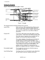
Using the Keypad
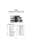
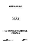
Figure 1 below shows the keypad in detail.
Levels LEDs (Set or
Unset)
32 character by two line
Liquid Crystal Display
(LCD)
Power
Optional programmable
panic alarm keys. Press
keys 1 and 3 together
Level setting keys
Optional programmable
control function keys.
Press keys 7 and 9
together.
Keyboard with
backlit soft rubber
keys
Menu and Enter keys
Figure 1. Keypad
The keypad has the following displays and controls:
Level LEDs
Each red Level LED (Light Emitting Diode) glows
when a Level is set. The LED is dark when the
Level is unset. Note that the installer may program
the system to switch the Level LEDs off after a
short time.
Power LED
The Power LED glows when the system is using
mains power. If the Power LED flashes slowly then
the mains power has been disconnected and the
system is running off the stand-by battery.
LCD
The system displays information and instructions
through the LCD (Liquid Crystal Display). The
system displays which detector has been triggered
by giving its zone number. You can use the keypad
to give detectors meaningful zone names. The
system will then display the names when the
detector is triggered (ask your Installer for details).
Illuminated keypad
The keypad can be set up so that the keys are
illuminated from behind.
Level Setting Keys
Use these keys to set individual Levels. (Note that
you will have to use your access code first.)
6
496256 Issue 1
1. Introduction
Panic Alarm Keys
Press keys 1 and 3 together to raise a personal
attack alarm. (Check with your Installer that your
system is programmed with this function.)
Control Function Keys
Your system may be fitted to control other devices
such external lighting. Press keys 7 and 9 together
to activate or deactivate the device. (Check with
your Installer that your system is programmed with
this function.)
Menu Key
The Menu key lets you start programming the
system so that you can change some of its functions (see "6. Supervisor"). While programming, the
Menu key acts as an Escape key, and also lets you
leave programming and return to the normal time
and date display.
Enter Key
The Enter key tells the system that you have
finished entering an access code (or other command).
About This Guide
The rest of this guide tells you how to use the system in more detail:
2. Everyday Operation
Describes how to set and unset the system.
3. After an Alarm
Tells you how to switch off the sounders after an
alarm, how to see what caused the alarm, and how
to reset the system so that it can be used again.
4. Special Functions
Tells you how to use the more advanced features
of the system.
5. Programming Chart
Summarises all the commands available to the
user.
6. Supervisor
Tells you how to control who has access to the
system, and how to limit what they can do. This
section is intended for someone who is responsible
for the whole alarm system.
496256 Issue 1
7
2. Everyday Operation
The 8136 provides several different ways for setting the system. All methods
(except using a Keyswitch) require entering your access code at the keypad.
The Keyswitch method uses a key in a special switch. "Setting the System"
below describes each method. Ask you Installer to provide the method that
suits your site best.
During installation the Installer programs the system to create an exit route
for your premises. When setting the system you must follow this route to
leave the premises. Similarly you must follow a specified entry route when
going into the premises in order to unset the system. If you stray from these
routes you may cause a false alarm.
Note: The system may be programmed so that your access code can set some
Levels but not others. See "6. Supervisor".
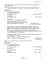
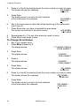
Setting the System
Timed Setting
With Timed Setting the system sets after a programmed exit time. Ask your
Installer to make sure the exit time is long enough for you to leave the
premises and close the final door. The exit time starts when you finish
entering the set command at the keypad. During the exit time the keypads
give a continuous exit tone to warn you that the timer is running. If you hear
an interrupted tone from the keypad when you try to set the system then a
detector is being triggered. (This is normal when you are walking past Entry
Route detectors.) Make sure that everyone is out of the premises and all
doors and windows are closed.
1. Key in your access code at the keypad.
2. Press the appropriate Level button followed by Enter.
The keypad starts the continuous exit tone, the
Level LED flashes, and the display shows:
AREA READY
LEAVE
3.
Leave via the designated exit route. Close the final door.
At the end of the exit time the system sets, and stops the exit tone. Your
Installer may have programmed the system to light a LED to show
which Level is set.
You can also set the system by entering your access code and pressing
Enter. The system will set to the highest Level that the Installer has programmed.
8
496256 Issue 1
2. Everyday Operation
If you do not close the final door before the end of the exit time then the
system gives an internal alarm and does not set. Go back to the keypad and
unset the system, see "3. After an Alarm".
Note: Some Levels on your system may be programmed for Silent Set. When
setting these Levels the system does not give any tones from the keypads.
Final Door
With Final Door setting the system sets seven seconds after you close the
last door.
1. Close all doors and windows.
2. Key in your access code at the keypad.
3. Press the appropriate Level button followed by Enter.
The keypad starts the continuous exit tone, the
Level LED flashes, and the display shows:
AREA READY
LEAVE
4.
Leave via the designated exit route and close the final door.
The system sets and stops the entry/exit tone seven seconds after you
close the final door.
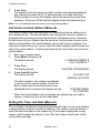
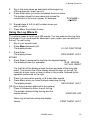
Exit Terminate Button
In Exit Terminate Button setting the system completes setting after you press
a button mounted outside the premises by the final door.
1. Close all doors and windows.
2. Key in your access code at the keypad.
3. Press the appropriate Level button followed by Enter.
The keypad starts the continuous exit tone, the
Level LED flashes, and the display shows:
AREA READY
LEAVE
4.
5.
Leave via the designated exit route. Close the final door.
Press the exit terminate button.
The exit tone stops and after seven seconds the system sets.
Note: The Installer may have programmed your system to set after a fixed time even
if you do not press the exit terminate button. This is to make sure your
premises are protected even if you forget to press the exit terminate button.
Ask your Installer how your system is set up.
Instant Set
With Instant Setting the system sets as soon as you complete entering the
set command from the keypad.
496256 Issue 1
9
2. Everyday Operation
1.
2.
3.
Close all doors and windows.
Key in your access code at the keypad.
Press the appropriate Level button followed by Enter.
The system sets immediately. The Level LED glows to show which
Level is set.
Keyswitch Setting
1.
2.
Close all doors and windows.
Check that the Ready lamp on the keyswitch is glowing, if your keyswitch is fitted with one.
If the lamp is not glowing then one or more detectors are being triggered.
3.
Turn the keyswitch (normally fitted outside the protected area).
Depending on how your system is programmed, the system may set
instantly or after a fixed delay, or when you close a final door or press
an exit terminate button.
Note that some keyswitches have two setting positions: "Full" and "Part". Ask
your Installer which parts of your premises are covered by each of these
positions.
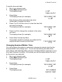
Setting an Area
Your system may be set up so that each Level key covers several distinct
Areas. You can set the system to guard one Area in a Level but leave the
others unset. Ask your Installer which Areas are covered by each Level key.
To set an Area:
1. Close all doors and windows make sure everyone is out of the area.
2. Key in your access code at the keypad.
3. Press the appropriate Level button.
4. Key in the Area number followed by Enter.
The keypad starts the continuous exit tone, the
Level LED flashes, and the display shows:
AREA READY
LEAVE
Depending on how your system is programmed, the system may set
instantly or after a fixed delay, or when you close a final door or press
an exit terminate button.
If the System Will Not Set
If the end station has detected a problem with one or more of the detectors
then the keypad will give a "beep" and show either a fault or a trouble
message.
10
496256 Issue 1
2. Everyday Operation
A fault message means that one of the detectors is being triggered (for
example, a door or window is open). The system will not set until you
have cleared all the faults.
A trouble message means that one of the detectors may be reporting that it
has a technical problem. The system can still set when there is a trouble
message, but you should report the message to you Installer.
For both types of message the keypad display can show you which zones
have problems.
For faults the displays shows (for example):
SETTING STOPPED
02 FAULTS EXIST
The system cannot finish setting because two detectors are being
triggered.
1.
Press the A or B keys.
The display shows each zone that is being triggered.
2.
Press A or B repeatedly until you have seen all the faults. Note down the
zones reported.
Go to each zone and find out what is triggering the detector. If possible
remedy the fault.
Go back to the keypad, press Menu, and try to set the system again.
For trouble messages the displays shows
(for example)
ZONES IN TROUBLE
1 FAULT
3.
4.
The system can still set.
1.
Press the A or B keys.
The display shows the zone that is reporting trouble.
2.
Press A or B repeatedly until you have seen all the trouble messages.
Note down the zones reported.
Press Enter.
The display shows:
AREA READY
LEAVE
3.
4.
Leave via the designated exit route. Close the final door.
Zones giving trouble reports do not affect the system security.
Your alarm system will still work correctly. Contact your alarm
company to let them check the system.
496256 Issue 1
11
2. Everyday Operation
Unsetting the System
If You Have a Keyswitch
Turn the keyswitch to OFF. The system unsets immediately.
Using the Keypad
They system has a programmed entry time. Ask your Installer to make sure
the entry time is long enough for you to enter by the designated entry route,
get to the keypad and unset the system.
The entry time starts when you open the designated door on the entry route.
During the entry time the keypads give a "galloping" entry tone to warn you
that the timer is running.
1. Enter the premises through the designated entry route and go to the
keypad.
As you enter the premises the system starts the entry timer and the
keypad gives the entry tone (a "galloping" tone).
2.
Key in your access code at the keypad and EITHER:
Press Enter to unset the whole system
OR press a Level key followed by Enter to unset a specific Level
OR press a Level key, enter an Area number, and press Enter to unset
a specific Area.
The entry tone stops. The system is now unset.
WARNING: If you enter your premises and the keypad is silent
then there may be an intruder.
Tamper Faults
The system's anti tamper circuit has been designed to guard the against
damage to the system's cases or wiring. If you hear an internal alarm and the
display shows one of the following displays, then the anti tamper circuit has
been broken.
END STN TAMPER
Someone has opened the end station lid.
A01:TAMPER ZONE 004
(Example) The tamper circuit to zone 4 in area 1
has been cut.
SOUNDER TAMPER
Someone has opened the external bell casing
or cut the cable to the bell.
TAMPER K02:
(Example) Keypad number two has been
opened, or the cable to it cut.
Note the location of the tamper reported on the display and call your alarm
company.
12
496256 Issue 1
3. After an Alarm
When your system raises an alarm you must disarm it in order to switch off
the sounders and strobes. The system keeps a record of which zone(s)
triggered the alarms, and shows the zone on the keypad display. Once you
have disarmed the system, the system must be reset before you can start
using it again.
Fire Alarm
The system gives a fire alarm by sounding a warbling tone from the keypads
and alarm sounder. The keypad shows the message:
*** FIRE ***
LEAVE BUILDING
1.
2.
Evacuate the premises and call the Fire Brigade. Do not attempt to
unset the alarm.
When the premises are safe, follow the instructions below.
Disarming the System
1.
2.
Go to the keypad via the entry route.
Key-in your access code and press Enter.
The sounders go quiet and the display shows:
followed by the cause of the alarm
(for example):
3.
SYSTEM DISARMED
RESET REQUIRED!
A01:GROUND FLOOR
DINING ROOM
Establish the cause of the alarm and then carry on and reset the system.
Resetting the System
The 8136 has three different methods for resetting:
Customer Reset. You can reset the system yourself from the keypad or
using a keyswitch.
Engineer Reset. Someone from your alarm company must visit the
premises to reset the system from the keypad.
Remote Reset. Your alarm company will give you instructions over the
phone and a special code so that you can reset the system from the
keypad.
Ask your alarm company what type of reset your system has.
496256 Issue 1
13
3. After an Alarm
Customer Reset
From Keypad
1. Key-in your access code and press Enter.
The keypad displays:
followed by the date and time.
SYSTEM RESET OK
You can now use your system as normal.
If the keypad displays (for example):
then a detector may still be triggered,
or the anti tamper protection on your system may
be damaged.
CANNOT RESET
02 FAULTS EXIST
1. Press A or B to see any more faults.
2. Contact your alarm company.
Using a Keyswitch
If your system is fitted with a momentary (springloaded) keyswitch you can
reset the system as follows:
1. Turn the key to Arm and release it back to Off.
The sounders go quiet.
2.
Turn the key to Arm again and release it back to Off.
You can now use your system as normal.
Engineer Reset
1.
2.
Key-in your access code and press Enter.
The keypad displays a message to call your
company, for example:
CALL ENGINEER
0123 456789
Call your alarm company and ask them to come and reset the system.
Remote Reset (CSID Code)
If your system uses remote reset, the display shows the words "CONTROL
CODE" and a four digit code on the bottom line.
1. Write down the four digits shown below the words "Control Code".
2. Contact your alarm company central station.
The central station will ask a few questions to make sure you are who
you say you are. They will then ask for the circumstances of the alarm.
If they do not need to send an Engineer to check the system they will
give you a "Reset Code".
3.
14
Key in the Reset Code on the keypad.
496256 Issue 1
3. After an Alarm
4.
Key in your access code and press Enter.
The display shows:
SYSTEM NOW
RESET!
RedCare or PC Reset
Your alarm company may use "RedCare" or PC Reset - ask your Installer.
1. Key-in your access code and press Enter.
2. Contact your alarm company central station.
The central station will ask you for a prearranged keyword and pass
code to make sure you are who you say you are. They will then ask for
the circumstances of the alarm. If they do not need to send an Engineer
to check the system they will reset your system by sending signals over
the telephone line.
3.
Key in your access code and press Enter.
The display shows:
SYSTEM RESET OK!
496256 Issue 1
15
4. Special Functions
Introduction
Some users may be allowed to perform a number of other functions, apart
from setting and unsetting the system. These functions are:
Setting the system so that some zones are bypassed or omitted.
Turning the chime function on or off.
Testing the zones and sounders.
Setting the time and date on the system's internal clock.
Changing zone names.
Reading the system log.
To use these functions you must key in your access code and then press
Menu followed by a number. In addition, the alarm system supervisor (see "6.
Supervisor") must program the system to allow each user access to individual menu number. The rest of this section assumes that the user has
access to the functions described.
Omitting Zones (Menu + Level)
Your system may be programmed so that you can omit individual zones
when setting the system. This function is useful, for example, if you have to
bypass a detector while decorating. Ask your Installer which zones can be
omitted. Note that omission is not permanent. You must omit the zone every
time you set the system.
To set with a zone omitted:
1. Key in your access code.
2. Press Menu.
The display shows:
1: SETTING
WITH OMISSIONS
3.
Press Enter.
The display shows:
4
Use the Level keys to display the Levels you
wish to set.
Press Enter.
The display shows:
5.
16
SET WHICH LEVELS
A
496256 Issue 1
OMIT ZONES?
4. Special Functions
4.
Press Enter.
The display shows (for example):
5.
Press A or B until the display shows the zone that you want to omit.
Note that some zones may not be programmed for omission.
HALL
Z02: ZONE NOT OMITTED
Note: You can also key in the zone number of the zone you want to omit. For
example, key in '005' for zone 5, or '025' for zone 25.
6.
7.
Press C or D until the display shows the words "IS OMITTED".
Press Enter.
The displays shows:
AREA READY
LEAVE
The system carries on to set as normal. The system will not raise an
alarm if the omitted zone is triggered. Note that the next time you set the
Level the system will treat the zone as normal; omission only lasts for
one setting/unsetting cycle.
Omitting 24 Hour Zones (Menu 2)
If your system is fitted with 24 hour detector zones, you may be able to omit
them if necessary. For example, your premises may have a fire door that you
occasionally open. Ask your Installer if this is possible.
If your system is programmed to allow you to omit a 24 hour zone, then:
1. Key in your access code.
2. Press Menu followed by 2.
The display shows:
2: OMIT 24 HOUR
ZONES?
3.
Press Enter.
The displays shows (for example):
4.
Press A or B until the display shows the 24 hour
zone that you want to omit. Note that some zones
may not be programmed for omission.
Press C or D until the display shows the words "IS OMITTED".
Press Enter to store the change.
The displays shows:
2: OMIT 24 HOUR
ZONES?
5.
6.
7.
FIRE DOOR
Z16: NOT OMITTED
Press Menu if you wish to stop programming the system.
The system will not raise an alarm if the omitted zone is triggered.
496256 Issue 1
17
4. Special Functions
To reinstate a 24 hour zone: repeat steps 1 to 6 but at step 5 press C or D to
make sure the display shows "UN-OMITTED".
Turning the Chime On/Off (Menu 3)
Your system may be programmed so that a chime tone sounds whenever
certain doors are opened. If you want to turn this feature on or off:
1. Key in your access code and press Menu followed by 3.
The display shows:
3: SYSTEM OPTIONS.
2.
Press Enter.
The system displays the current state of the
chime function:
CHIME
DISABLED
3.
Press A or B to change between "DISABLED" and "ENABLED".
The display shows:
CHIME
ENABLED
4.
Press Enter to save the change and to go on to change the internal
sounder volume. Otherwise press Menu twice to go back to the time
and date display.
Changing the Volume of the Internal Sounder
If your internal sounder is too loud or quiet, you can change its volume from
the keypad.
1. Key in your access code and press Menu followed by 3.
The display shows:
3: SYSTEM OPTIONS.
2.
Press Enter twice.
The display shows:
3.
Press A or B to change the volume of the internal sounder. There is a
choice of "V. HIGH", "HIGH", "MEDIUM", "LOW" and "V. LOW".
Press Enter to save the change and to go on to test the system. Otherwise press Menu twice to go back to the time and date display.
4.
SOUNDER VOLUME
V. HIGH
Testing the System (Menu 4)
You can set the system so that it will allow you to walk round the premises
and test each of the detectors (a walk test). At the same time you can also
test the external bell and strobe. Choose a time when the premises are
empty to carry out the test, otherwise people may trigger any movement
detectors before you do, and confuse the results of the test.
18
496256 Issue 1
4. Special Functions
If any detector fails the test then call your alarm company and ask them to
check the system.
Note: If your system is fitted with Fire, 24 hour or personal attack detectors, you
cannot walk test them. If you wish to test them call your alarm company.
Walk Test
1.
2.
Key in your access code.
Press Menu followed by 4.
The display shows:
3.
Press Enter.
The display shows:
4.
Press Enter.
The top line of the display shows the total
number of detectors to test, while the
bottom line shows the zone number of each
detector to be tested, for example:
5.
4: TEST OPTIONS
WALK TEST
13 ZONES TO DO
01 02 03 04 05 06 >
Walk round your premises and trigger each detector. Note: do not
trigger any Fire, 24 hour or personal attack detectors (they will not
appear in the list of detectors to be tested). If you do trigger a Fire, 24
hour or personal attack detector the system will raise an alarm.
As you trigger a detector the internal sounder gives a tone, and the zone
number disappears from the display.
If necessary press A or B to scroll through the list of zones to show any
not appearing on the display.
When all detectors shown on the list have been
tested successfully the display shows:
WALK TEST
COMPLETE
Note: You can abandon the test at any time by pressing Menu.
Bell Test
1.
2.
Key in your access code.
Press Menu followed by 4.
The display shows:
3.
Press Enter.
The display shows:
WALK TEST?
4.
Press B
The display shows:
BELL TEST ?
4: TEST OPTIONS
496256 Issue 1
19
4. Special Functions
5.
Press Enter.
The system turns the keypad sounder, strobe, and internal speaker(s)
and external sounder on for 12 seconds each, one after the other.
While the test is running the display shows the device that should be
operating. At the end of the test the display shows the date and time.
Note: You can abandon the test at any time by pressing Menu.
Call Out to Central Station (Menu 5)
Your alarm system may be connected to a central monitoring station by its
own telephone line. The central station can change the way your system is
programmed by sending a new program down the telephone line. However,
for extra security your system may be set up so that the alarm system must
call the central station; the central station cannot call into your system. The
instructions below show you how to make the alarm system start a telephone
call to the central station. Follow these steps when instructed to do so by the
central station:
1. Key in your access code.
2. Press Menu followed by 5.
The display shows:
5: ANSWER REMOTE
CALL FROM CS ?
3.
Press Enter.
The display shows:
4.
Press 4 and 6 together.
The display shows:
WAITING FOR RINGING
CALLING THE
CENTRAL STATION
The alarm system now makes one attempt
to connect to the central station. When the
alarm system and the central station have
established the connection the display shows:
SYSTEM UNDER
PC CONTROL
When the central station has completed reprogramming your alarm
system, it returns to its normal unset state.
Setting the Time and Date (Menu 6)
The end station contains an internal clock/calendar that runs as long as there
is power present (mains or stand-by battery). The system uses this clock to
mark the time and date on the system log. If the power supply fails for any
reason, and the stand-by battery is low, then the system loses track of the
correct time and date.
20
496256 Issue 1
4. Special Functions
To set the time and date:
1. Key in your access code.
2. Press Menu followed by 6.
The display shows:
3.
6: SET
TIME & DATE ?
Press Enter.
The display shows (for example):
Note that one of the characters has a bar
underneath it (called the cursor).
4.
5.
6.
Press C or D until the cursor is under the item that
you want to change.
The display shows (for example):
Press A or B to change the numbers to the value
you want.
The display shows (for example):
Press Enter followed by Menu.
The system saves the change you made and the
display shows the new time and date:
TUE 26 MAR 1997
12:18
TUE 26 MAR 1997
12:18
TUE 26 MAR 1997
13:18
TUE 26 MAR 1997
13:18
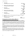
Changing Summer/Winter Time
You can program the system in advance to change its internal clock for the
summer/winter time change over. You do this by entering the date of the
next change, and selecting either one hour forward (winter to summer) or one
hour back (summer to winter). At the date you set the system alters its clock
by the amount you selected.
1. Key in your access code.
2. Press Menu followed by 6.
The display shows:
6: SET
TIME & DATE ?
3.
Press Enter.
The display shows (for example):
4.
Press Enter.
The display shows:
TUE 26 MAR 1997
12:18
SET SUMMER
WINTER TIME?
496256 Issue 1
21
4. Special Functions
5.
Press Enter.
The display shows (for example):
6.
Press A or B to change the month.
The display shows (for example):
7.
Press Enter.
The display shows:
8.
Press A or B to change the day.
The display shows (for example):
9.
Press Enter.
The display shows:
SET DATE =
26 Oct
SET DATE =
26 Nov
SET DATE =
26 Nov
SET DATE =
05 Nov
SET TIME
BACK 1 HOUR
10. If necessary press A or B to select either "No Change" or "Forward 1
Hour"
11. Press Enter to store the change.
The display shows:
6: SET
TIME & DATE ?
Changing Area and Zone Names (Menu 7)
The system allows you to store names for each detector zone. In addition,
the installer groups detector zones into areas, and you can give each area its
own name. The display shows the names when the system raises an alarm,
or if you are using some of the special functions. Each area or zone name
can be a maximum of 16 characters long, including spaces and punctuation
marks.
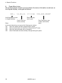
Although the keypad only shows numbers, the system lets you enter letters
one at a time by pressing a number key repeatedly until the display shows
the letter you want. Each number key gives its own number and three letters
of the alphabet.
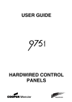
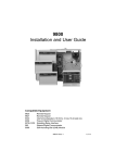
The figure below shows which letters belong to each number key. When
keying in a name, find the letter you want on Figure 2, then press the key
shown the correct number of times. Use the right arrow key to move the
cursor to the next space for a new letter.
22
496256 Issue 1
4. Special Functions
For Key in For Key in For Key in
For
Key in
1
1
A
11
K
444
U
7777
2
2
B
111
L
4444
V
88
3
3
C
1111
M
55
W
888
4
4
D
22
N
555
X
8888
5
5
E
222
O
5555
Y
99
6
6
F
2222
P
66
Z
999
7
7
G
33
Q
666
Space
9999
8
8
H
333
R
6666
'
00
9
9
I
3333
S
77
(
000
0
0
J
44
T
777
)
0000
Figure 2. Letters Generated by Each Number Key
If you make a mistake, press C or D to move the cursor over the letter you
want to change, and key in the new letter. If you want to delete a name
completely, press D repeatedly to move the cursor under the extreme left
hand character of the name. Press D again. The display clears the old name.
To Change Area Names:
1.
2.
Key in your access code.
Press Menu followed by 7.
The display shows:
3.
Press Enter.
The display shows:
4.
Press Enter.
The display shows:
7: CHANGE AREA &
ZONE NAMES ?
CHANGE
AREA NAME ?
A01:NAME =
AREA 01
The top line of the display shows the area number. The bottom line of
the display shows the current area name. Note that the cursor is under
the area number.
496256 Issue 1
23
4. Special Functions
4.
Press A or B until the display shows the area number you wish to name.
The display shows (for example):
A02:NAME =
AREA 02
5.
Press Enter.
The display cursor moves to the first character
of the area name (for example):
6.
A02:NAME =
AREA 01
7.
Key in the area name as described at the beginning of this subsection
(see Figure 2).
Press Enter when you have completed the area name.
The cursor moves back to the area number:
A02:NAME=
KITCHENS
8.
9.
Repeat steps 4 to 7 for any other areas you wish to name.
Press Menu three times to stop
1.
2.
Key in your access code.
Press Menu followed by 7.
The display shows:
3.
Press Enter.
The display shows:
4.
Press A.
The display shows:
5.
Press Enter.
The display shows:
6.
Press A or B until the display shows the zone number you wish to name.
The display shows (for example):
Z03:NAME =
ZONE 003
7.
Press Enter.
The display cursor moves to the first character
of the zone name (for example):
To Change Zone Names
24
7: CHANGE AREA &
ZONE NAMES ?
CHANGE
AREA NAME ?
CHANGE
ZONE NAME ?
Z01:NAME=
ZONE 001
496256 Issue 1
Z03:NAME =
ZONE 003
4. Special Functions
8.
9.
Key in the zone name as described at the beginning
of this subsection (see Figure 2).
Press Enter when you have completed the zone name.
The system saves the new name and moves the
cursor back to the zone number, for example:
Z03:NAME =
LOUNGE
10. Repeat steps 6 to 9 for all the other zones you
want to name.
11. Press Menu three times to stop.
Using the Log (Menu 9)
The system keeps a log of up to 500 events. You can examine this log from
the keypad. If you have a printer attached to your system you can also print
the log. To use the log:
1. Key in your access code.
2. Press Menu followed by 9.
The display shows:
9: LOG FUNCTIONS
3.
Press Enter.
The display shows:
VIEW EVENT LOG ?
EITHER:
4. Press Enter to examine the log from the keypad display.
The display shows (for example):
15:28 26/03/96
U01:A04: UNSET
The first line of the display shows the time and date of the recorded
event. The second line of the display shows the user on the left, followed by a zone- area- or level number in the middle, followed by the
operation performed on the right.
5.
6.
Press A to see earlier events, or B to see later events.
Press Menu when you have finished examining the log.
The display shows:
VIEW EVENT LOG ?
OR (if you have a printer attached to the system)
7. Press A followed by Enter to print the log.
The system starts printing the log and the
display shows:
When log is finished printing the display
shows:
496256 Issue 1
PRINTING LOG
PRINT EVENT LOG ?
25
4. Special Functions
8. Press Menu twice.
The printed record of each event contains the same information as shown on
the keypad display, arranged as follows:
001:
13:09:55
27/3/96
Audit Number (not shown
Event Date (day,
on keypad displays)
month, year)
Event Time (hour,
minute, second)
U02:A02:UNSET
Event Description (user
number, area number,
event)
Notes:
In the event description you may see the following user numbers:
U00
when the installer has been programming the system.
U96
when a central station has carried out a remote reset (PC reset).
U98
when the system has been set by a keyswitch.
U99
when<Downloader has been remotely setting/unsetting the system.
26
496256 Issue 1
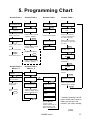
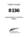
5. Programming Chart
Access Code +
Access Code +
Access Code +
Access Code +
1:SETTING
WITH OMISSIONS
3: SYSTEM
OPTIONS
5:ANSWER REMOTE
CALL FROM CS?
6: SET TIME AND
DATE
ENTER
ENTER
SET WHICH LEVELS
ABCD
Use Level keys to select
Level. Press Enter.
ENTER
WAITING FOR
RINGING
chime
Press A or B to change
enabled - disabled.
OMIT ZONES ?
Press 4 and 6 together.
ENTER
sounder volume
CALLING THE
CENTRAL STATION
Press A or B to change
sounder volume.
system under pc
control
ENTER
Press A or B to select
zone*.
Press C or D to Omit.
ENTER
System starts to set.
ENTER
TUE 07 JAN 1997
15:30
(Supervisor only)
Press C or D until the
cursor is under the item
you want to change.
Press A or B to change
the numbers to the value
you want.
ENTER
SET SUMMER
WINTER TIME?
ENTER
ENTER
remote set/unset
SET DATE =
DD MMM
Press A or B to change
enabled - disabled.
Press A or B to change
the MONTH
ENTER
Access Code +
Menu + 2
Access Code +
Menu + 4
2: OMIT 24 HOUR
ZONES?
4: TEST OPTIONS
Press A or B to change
the DAY
ENTER
ENTER
fire door
znn: not omitted
SET DATE =
DD MMM
ENTER
Walk test
A
Bell test
ENTER
Press A or B to
select zone*.
nn zones to do
01 02 03 04 05 06 >
Press C or D to
Omit.
Trigger each detector
shown in display. Press
Menu to abandon test.
SET TIME
FORWARD 1 HOUR
ENTER
Testing:
Keypad sounder
Press A or B to forward,
backward or no change.
ENTER
ENTER
walk test COMPLETE
ENTER
Testing:
Strobe
Testing:
Speaker
Testing:
Bell
System operates
sounder, strobe,
speaker and bell for 12
seconds each. Press
Menu to abandon test.
* Instead of pressing A and B
keys to select users, zones or
areas, you can key in the
number if you know it already.
PTO
496256 Issue 1
27
5. Programming Chart
Access Code +
Menu + 7
Access Code + Menu + 8
(Supervisor and restricted
access for Master User)
7:CHANGE AREA &
ZONE NAMES?
8:USER
INFORMATION
ENTER
ENTER
A
CHANGE
AREA NAME?
EDIT USER
INFORMATION?
CHANGE
ZONE NAME?
ENTER
ENTER
ENTER
A01:NAME=
AREA 01
Press A or B to select
user number*.
U01:NAME=
001:NAME=
ZONE 001
ENTER
Press A or B until the
display shows the area
you want to name*.
Press A or B until the
display shows the zone
you want to name*.
Key in Area name.
Key in zone name.
ENTER
ENTER
U02:CODE=
ENTER
U02:P01:
ENTER
ENTER
U02:DURESS CODE
DISABLED
Access Code +
Menu + 9
U02: SYSTEM USE
Key in new name.
Key in new code twice to
confirm.
Press A or B to change
access rights.
ENTER
Repeat for all
partitions.
ENTER
ENTER
9:LOG FUNCTIONS
ENTER
ENTER
ENTER
Press A or B to enable/
disable.
Press A or B to select
FULL USE or ARM ONLY
ENTER
VIEW EVENT LOG?
A
ENTER
20:48
13/01/97
U01: A08:UNSET
PRINT EVENT LOG?
U02: OMIT ZONES
ENTER
Press A or B to permit or
not permit.
ENTER
ENTER
PRINTING LOG
U02: LOG ACCESS
ENTER
Press A or B to permit or
not permit.
ENTER
Press A to see older
entries, press B to see
newer entries.
U02: CHANGE
NAMES
ENTER
Press A or B to permit or
not permit.
ENTER
Press Menu to leave log.
U02: RESET
ENTER
Press A or B to permit or
not permit.
ENTER
U02: CHANGE DATE
* Instead of pressing A and B
keys to select users, zones or
areas, you can key in the
number if you know it already.
Press A or B to permit or
not permit.
ENTER
U02: MASTER USER
ENTER
ENTER
U02:NAME=
28
ENTER
496256 Issue 1
Press A or B to enable or
disable.
6. Supervisor
Introduction
This section describes the facilities available to the alarm system supervisor.
To be a supervisor you must use a special access code (see below). The
supervisor can:
Change all user's access codes.
Restrict users to individual Partitions.
Set up Duress Codes.
Restrict users so that they can set the system but not unset it.
Prevent users from resetting the system.
The supervisor can also allow or deny access to the following special functions described in section 4:
Menu 1 and 2 - Omit Zones.
Menu 6 - Set Time and Date.
Menu 7 - Change Area and Zone Names.
Menu 8 - Change User Information.
Menu 9 - Event Log.
In addition, the supervisor can prevent a central station setting the
system remotely.
Access Codes
The 8136 can store up to 95 different user access codes. For security you
should give one code to each person who has responsibility for setting and
unsetting the system. Do not allow users to share codes.
Every time someone enters an access code on the keypad the system
records the event in its log. To distinguish all the users and keep their access
codes hidden, the log shows each user as a number, for example "User 02",
"User 03" and so on.
The supervisor's access code is always shown as "User 01". User 01 always
has access to all menus.
Restricting Users to Partitions
If you wish to restrict users to particular areas covered by the alarm system
ask the Installer to set up a Partition. The 8136 can support four Partitions,
496256 Issue 1
29
6. Supervisor
each of which behaves as an independent alarm system. At the same time
the Installer will allocate one or more Level keys to each of the Partitions.
Make sure you know which Level keys belong to each Partition, and which
areas they cover.
Once the Installer has created the Partitions, you must then assign each user
to one or more of the Partitions.
Note: Any user with access to one Level in a Partition also has access to all the
other Levels in the same Partition.
Master Users
The supervisor can create Master Users with some or all of the privileges
used by the Supervisor. Each Master User should be assigned to one or
more Partitions as appropriate.
A Master User can change the privileges of any other user belonging to the
same Partition. No Master User can see or change the details of any user
that belongs to another Partition. Most importantly, a Master User cannot see
or change the details of the Supervisor (User 01).
Duress Code
If your system is connected to a central monitoring station, you may want to
give some of the users a Duress Code. If a user enters the Duress Code
while the system is set, then the end station unsets the system, but at the
same time sends a silent alarm call to the central monitoring station. This
facility is designed for times when a user is being forced to unset the alarm
system by an intruder.
Note that a Duress Code occupies one user number. The duress code
cannot operate any of the special functions described in "4. Special Functions".
Restricting users to Arm Only
Some of the people who enter your premises may not need full access to all
the alarm system functions. You can give these users Arm Only status. This
means that the user can set the system, but not unset it. This facility is
designed for people like cleaners who may need to secure your premises
after the daytime occupants have left.
Changing Access Codes and User Privileges (Menu 8)
You must start from menu 8 for all the facilities described in this section.
To start menu 8:
1. Key in the User 01 access code.
30
496256 Issue 1
6. Supervisor
2.
Press Menu followed by 8.
The display shows:
3.
Press Enter.
The display shows:
8: USER
INFORMATION
EDIT USER
INFORMATION ?
Changing User Names
The 8136 can store a 16 character name against each user code. To change
the name:
1. Start menu 8.
2. Press Enter until the top line of the display shows: "U01:NAME ="
3. Press A or B until the top line of the display shows the user number
whose name you wish to change. (You can also key in the user number
if you already know it.)
The display shows (for example):
U03:NAME =
NOT IN USE
4.
Press Enter.
The display cursor moves to the bottom line:
5.
Key in the new name. Use the in the same way as you would for changing the zone names (see Figure 2).
The display shows the new name (for example):
U03:NAME =
MARY_
6.
Press Enter when you have completed the name.
The system stores the name and the display shows "U03:CODE ="
7.
Press Menu three times to leave programming.
U03:NAME =
NOT IN USE
Changing Access Codes
The Installer can program your system to use either four-digit or six-digit
access codes. Check with the Installer which type of code is in use.
If your system does NOT use Partitions, but is simply a Full/Part set system,
then all access codes apply to all Levels. You cannot assign any access code
to a specific Level.
1. Start menu 8.
2. Press Enter until the top line of the display shows "U01:CODE =".
3. Press A or B until the display shows the user number whose access
496256 Issue 1
31
6. Supervisor
code you wish to change. (You can also key in the user number if you
already know it.)
The display shows (for example):
U02:CODE =
****
Note: If your system is using six-digit access codes the bottom line of the display will
show "******".
4.
5.
Press Enter.
The display shows:
U02:CODE =
_
Key in the digits of the new access code and press Enter. Note that the
display shows " * " characters instead of numbers. This is to prevent
anyone reading the access code over your shoulder.
Note: To delete an existing code key in "0000" ("000000" for six digit access codes).
The display shows:
6.
CONFIRM NEW CODE
_
Key in the same digits again.
After you key in the last digit the display
changes to show (for example):
If the display shows:
then you did not key in the confirmation correctly.
Press Menu and go back to step 4.
If the display shows:
then another user already has that access code.
Press Menu and go back to step 4.
U02:P01:
NO ACCESS
CODE MISMATCH
CODE ALREADY
IN USE
Changing Partition Access
If your system does use Partitions then once you have created a set of
access codes you must then give them access to the appropriate Partition(s).
Each access code will then work only on the Partition(s) you have assigned.
Ask your Installer which Partition (1, 2, 3, or 4) is assigned to each of the
Level keys. Then:
1. Start menu 8.
2. Press Enter until the top line of the display shows "U01:P01:".
3. Press A or B until the display shows the user number whose Partition
access you wish to change (or key in the number directly).
The display shows (for example):
U02:P01:
NO ACCESS
32
496256 Issue 1
6. Supervisor
4.
Press Enter.
The display shows the cursor at the beginning of
the bottom line:
U02:P01:
NO ACCESS
5.
Press A or B to change access to the Partition.
The display shows (for example):
6.
Press Enter.
The display shows the next Partition (for example)
7.
Repeat steps 4 to 6 to give the correct access to all four Partitions.
When you press Enter after changing access
for Partition 4 the top line of the display shows:
U03:DURESS CODE
DISABLED
U02:P01:
HAS ACCESS
U02:P02:
NO ACCESS
Don't forget to tell each user which Level key they must use for each Partition, or that keying in their access code followed by Enter sets the highest
Level assigned to their access code.
Setting Up a Duress Code
A duress code is a special access code used for emergencies only. After
entering a duress code the system does not allow access to any of the
special functions listed in section 4. In addition, the system will not let you
give User 01 a duress code.
1. Start menu 8.
2. Press Enter until the top line of the display shows "U01:CODE=".
3. Press A or B until the display shows the user number you wish to use
for the duress code (or key in the number directly).
The display shows (for example):
U14:CODE =
****
4.
Press Enter.
The display shows:
5.
Key in the duress code and press Enter.
The display shows:
6.
Key in the duress code again.
When you key the last digit of the duress code
the top line of the display shows:
U14:CODE=
_
496256 Issue 1
CONFIRM NEW CODE
_
U14:P01:
33
6. Supervisor
7.
Press Enter until the display shows:
8.
Press A or B to change from "DISABLED" to "ENABLED".
The display shows:
U14:DURESS CODE
ENABLED
9.
Press Enter.
The system saves the change and the top line of
the display shows:
U14:DURESS CODE
DISABLED
U14:SYSTEM USE
If you want to remove a duress code from a user number, follow steps 1 to 9
again but at step 8 press A or B to change the bottom line of the display to
"DISABLED".
Giving a User Arm Only Access
1.
2.
3.
Start menu 8.
Press Enter until the top line of the display shows "U01:SYSTEM USE".
Press A or B until the display shows the correct user number (or key in
the user number directly).
The display shows (for example):
U02:SYSTEM USE
FULL USE
4.
Press Enter.
The display moves the cursor to the bottom line:
5.
6.
Press A or B to change between "FULL USE" and "ARM ONLY".
Press Enter.
The system saves the change and the top line of
the display shows:
U02:OMIT ZONES
U02:SYSTEM USE
FULL USE
Allowing a User to Omit Zones
1.
2.
3.
Start menu 8.
Press Enter until the top line of the display shows "U01:OMIT ZONES".
Press A or B until the display shows the correct user number (or key in
the user number if you already know it).
The display shows (for example):
U02:OMIT ZONES
NOT PERMITTED
4.
Press Enter.
The display moves the cursor to the bottom line:
34
496256 Issue 1
U02:OMIT ZONES
NOT PERMITTED
6. Supervisor
5.
6.
Press A or B to change the bottom line between "NOT PERMITTED"
and "PERMITTED".
Press Enter.
The system saves the change and the top line of
the display shows:
U02:LOG ACCESS
Giving a User Log Access
1.
2.
3.
Start menu 8.
Press Enter until the top line of the display shows "U01:LOG ACCESS".
Press A or B until the display shows the correct user number (or key in
the user number if you already know it).
The display shows (for example):
U02:LOG ACCESS
NOT PERMITTED
4.
Press Enter.
The display moves the cursor to the bottom line:
5.
Press A or B to change the bottom line between "NOT PERMITTED"
and "PERMITTED".
Press Enter.
The system saves the change and the
top line of the display shows:
U02:CHANGE NAMES
6.
U02:LOG ACCESS
NOT PERMITTED
Allowing a User to Change Zone Names
1.
2.
3.
Start menu 8.
Press Enter until the top line of the display shows "U01:CHANGE
NAMES".
Press A or B until the display shows the correct user number (or key in
the user number directly).
The display shows (for example):
U02:CHANGE NAMES
NOT PERMITTED
4.
Press Enter.
The cursor moves to the bottom line:
5.
Press A or B to change the bottom line between "NOT PERMITTED"
and "PERMITTED".
Press Enter.
The system saves the change and the
top line of the display shows:
U02:RESET
6.
496256 Issue 1
U02:CHANGE NAMES
NOT PERMITTED
35
6. Supervisor
Allowing a User to Reset After an Alarm
1.
2.
3.
Start menu 8.
Press Enter until the top line of the display shows "U01:RESET".
Press A or B until the display shows the correct user number (or key in
the user number directly).
The display shows (for example):
U02:RESET
NOT PERMITTED.
4.
Press Enter.
The display moves the cursor to the bottom line:
5.
Press A or B to change the bottom line between "NOT PERMITTED"
and "PERMITTED".
Press Enter.
The system saves the change and the
top line of the display shows:
U01:CHANGE DATE
6.
U02:RESET
NOT PERMITTED
Allowing a User to Change the Time and Date.
1.
2.
3.
Start menu 8.
Press Enter until the top line of the display shows "U01:CHANGE
DATE".
Press A or B until the display shows the correct user number (or key in
the user number directly).
The display shows (for example):
U02:CHANGE DATE
NOT PERMITTED
4.
Press Enter.
The display moves the cursor to the bottom line:
5.
Press A or B to change the bottom line between "NOT PERMITTED"
and "PERMITTED".
Press Enter.
The system saves the change and the top line
of the display shows (for example):
U03:MASTER USER
6.
U02:CHANGE DATE
NOT PERMITTED
Creating a Master User
1.
2.
3.
Start menu 8.
Press Enter until the top line of the display shows "U01:MASTER
USER".
Press A or B until the display shows the correct user number (or key in
the user number directly).
The display shows (for example):
U02:MASTER USER
ENABLED
36
496256 Issue 1
6. Supervisor
4.
Press Enter.
The display moves the cursor to the bottom line:
5.
Press A or B to change the bottom line between "ENABLED" and
"DISABLED".
Press Enter.
The system saves the change.
6.
7.
U02:CHANGE DATE
ENABLED
Press Menu three times to return to the normal unset state, with the
display showing the time and date.
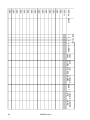
User Records
Inside the back cover is an example table for keeping records of the users
who have access to your alarm system. You can write on this table, photocopy it if you have more than 16 users, or use the information to design your
own forms. Remember, DO NOT write down any access codes.
Disabling Remote Setting
If your alarm system is connected to a central station by telephone line, it
may be programmed to allow the central station to set and unset the system
without your help. If you do not wish to allow this, or if you DO want to allow
your central station to set and unset your alarm system, then:
1. Key in your access code and press Menu followed by 3.
The display shows:
3: SYSTEM OPTIONS.
2.
Press Enter three times.
The display shows:
3.
4.
Press A or B to change between DISABLED and ENABLED.
Press Enter then Menu to save the change.
REMOTE SET/UNSET
DISABLED
496256 Issue 1
37
Index
Exit route ................................................... 8
Exit terminate button ................................ 9
Exit time .................................................... 8
defintion .................................................................. 4
Symbols
Exit tone .................................................... 8
definition ................................................................. 4
24 hour zone ........................................... 17
definition ................................................................. 4
A
F
Access codes ......................................... 29
Fault message ........................................ 11
Final door setting ...................................... 9
Final Exit door
Area
Fire alarm ................................................ 13
Area names ............................................ 22
Area setting ............................................ 10
Arm only .................................................. 30
G
changing ............................................................... 31
definition ................................................................. 4
definition ................................................................. 4
setting up .............................................................. 34
definition ................................................................. 4
Galloping tone ........................................ 12
I
B
Bell test
Instant setting ......................................... 10
Internal alarm ............................................ 9
Bypass .................................................... 16
Internal sounder
C
Interrupted tone ........................................ 8
how to .................................................................... 19
definition ................................................................. 4
changing volume ................................................... 18
Central station ........................................ 20
K
Chime ..................................................... 16
Keypad
call out to .............................................................. 20
turning on/off ......................................................... 18
Cleaners ................................................. 30
Clock ....................................................... 20
Control code ........................................... 14
Customer reset ....................................... 14
D
Disarm .................................................... 13
definition ................................................................. 4
how to .................................................................... 13
Display ............................................... 6, 22
Duress code ........................................... 30
setting up .............................................................. 33
E
Engineer reset ........................................ 14
Enter key ................................................... 7
Entry route ......................................... 8, 12
Entry time ............................................... 12
description .............................................................. 6
unsetting from ....................................................... 12
Keyswitch .................................................. 8
definition ................................................................. 4
full and part positions ........................................... 10
setting ................................................................... 10
unsetting ............................................................... 12
L
Letters ..................................................... 22
Level
definition ................................................................. 5
keys .................................................................. 6, 30
Lighting control ......................................... 7
Log ............................................ 16, 20, 29
granting access ..................................................... 35
printing .................................................................. 25
using ..................................................................... 25
M
definition ................................................................. 4
Master user ............................................. 30
definition ................................................................. 4
Menu key .................................................. 7
Entry tone ............................................... 12
creating ................................................................. 36
Entry/Exit route
definition ................................................................. 4
38
496256 Issue 1
Index
N
U
Names
Unset
O
Unsetting ................................................. 12
User names
Omit ........................................................ 16
User privileges ........................................ 29
deleting ................................................................. 23
24 hour zones ....................................................... 17
definition ................................................................. 5
granting access ..................................................... 34
how to .................................................................... 16
definition ................................................................. 5
changing ............................................................... 31
W
Walk test ................................................. 18
how to .................................................................... 19
P
Z
Panic Alarm
description .............................................................. 5
keys ......................................................................... 7
Zone
definition ................................................................. 5
granting access to ................................................. 32
Zone names ..................................... 16, 22
Partition ................................................... 29
R
definition ................................................................. 5
problems ............................................................... 11
allowing users to change ...................................... 35
definition ................................................................. 5
RedCare reset ........................................ 15
Remote reset .......................................... 14
Remote setting
disabling ................................................................ 37
Reset ...................................................... 13
allowing users to ................................................... 35
definition ................................................................. 5
from keypad .......................................................... 14
from keyswitch ...................................................... 14
RedCare ................................................................ 15
using csid code ..................................................... 14
Reset code ............................................. 14
S
Set
definition ................................................................. 5
Setting ....................................................... 8
Silent alarm ............................................. 30
Silent set ................................................... 9
definition ................................................................. 5
Special functions .................................... 16
Supervisor ........................................ 29, 30
T
Tamper fault ............................................ 12
Testing .................................................... 18
Service Contact
Company. Name:
sounders ............................................................... 16
zones ..................................................................... 16
Day Tel:
allowing users to change ...................................... 36
how to set .............................................................. 20
Night Tel:
Time and date .................................. 16, 20
Timed setting ............................................ 8
Trouble message .................................... 11
496256 Issue 1
39
USER No. NAME
USER 01
USER
USER
USER
USER
USER
USER
USER
USER
USER
USER
USER
USER
USER
USER
USER
3
4 DURESS
PARTITION
1 2
ARM OMIT LOG
CHANGE
CHANGE MASTER
RESET
ONLY ZONES ACCESS NAMES
DATE
USER
496256 Issue 1
40