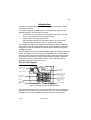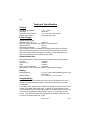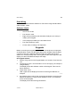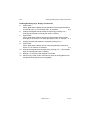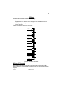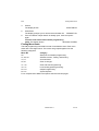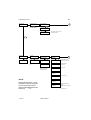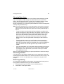
1
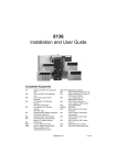
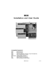
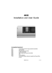
808
Installation and User Guide
Compatible Equipment
927
929
947
949
951
9040
9056
9076-01/2
8 character LCD keypad new style case
8 character LCD keypad
Portable printer ( Battery powered ) and power supply unit
Wall Mounted Printer Bracket
Printer lead
16 Ohm internal sounder
Plug-on Digital Communicator
Plug-on RedCare STU (manufactured by others)
Signalling Interfaces
496336 Issue 1
1 of 22
808
Introduction
The 808 is a programmable Alarm System suitable for domestic or small
commercial premises.
The system comprises an end station in a shielded case, and up to four
separate keypads. The end station provides:
•
Connections for up to eight Fully Supervised Loop (FSL) or Closed
Circuit zones (selectable during programming).
•
Three outputs, two fully programmable.
•
Pins for fitting a plug-on communication device. Any device that
complies with the Scantronic plug-on footprint can be fitted.
The installer can program the system from the keypad, which provides an
eight character Liquid Crystal Display (LCD). The programming interface is
arranged into a set of numbered menus that lead the installer through the
installation process.
The 808 software provides a flexible installation that can meet many different
needs. The system can provide for up to 8 identified users. The 808 allows
users to set the system to four different security Levels (for example full set
and three part sets) which can be programmed by the installer. Individual
zones can be programmed as Flexi-Zones™, which change behaviour
depending on which security Level is set.
The 927 LCD Keypad
Levels A to D LEDs
(Set or Unset)
8 Character Liquid
Crystal Display
Power
Optional programmable
panic alarm keys. Press
keys 1 and 3 together
Scroll and Level
setting keys
Optional programmable
control function keys.
Press keys 7 and 9
together.
Edit Keys
Keyboard with
backlit soft rubber
keys
Menu and Enter keys
Figure 1. 927 Operator Controls and Displays
The 927 LCD keypad provides an eight character super twist LCD display, a
green Power LED, and four red Level status LEDs. The 927 also provides
terminals for one zone, in addition to those supplied by the end station.
2 of 22
496336 Issue 1
808
Technical Specification
General
Operating temperature
Humidity
Dimensions (end station)
Weight (end station)
= -10º - +40ºC.
= 80% RH.
= h x w x d 300 x 300 x 80mm.
= Approximately. 5Kg.
Power Supply
System Power Supply
(Ambient Temp. 20 º. C)
= 900 mA.
With the system quiescent, this supply is used as follows:
808 end station
= 90 mA.
Each Remote Keypad
= 60 mA.
The remaining current is available for recharging the battery, and supply
attached devices through the 12V Aux terminals on the main connector.
With the system in alarm the battery can supply current additional to the
maximum available from the system power supply.
Output Protection
Self resetting thermal Polyswitches protect outputs at the following levels:
12V Aux
=1,350mA.
Keypad 12V
= 500mA.
Siren
= 750mA.
Batt (reverse connection)
= 2,500mA.
Bell, Strobe and OP1 are open collector outputs rated at 500mA.
Battery
Standby Battery
Battery Space
= 12 Volt, 6.5AH rechargeable lead-acid, Gel
Type battery.
= h x w x d 150 x 110 x 75 mm.
Keypad Wiring
Recommended maximum distances for the remote keypads from the end
station, using standard alarm cable is 100 metres per branch for the star
configuration.
For a daisy chain configuration the maximum length must take account of the
number of keypads sharing the cable. In general, a single keypad can be
connected at the end of a maximum of 300m of standard cable. If you wish to
connect more keypads the cable must be shorter, or the 0V wire must be
thicker. The criterion is that at the last keypad the voltage between 0V and
12V wires must be no less than 10.5V.
496336 Issue 1
3 of 22
Zone Wiring
808
Zone Wiring
The recommended maximum distance for FSL zones using standard alarm
cable is 200m - 300m.
Software Limits
The 808 can support:
•
One to four Levels.
•
Four Areas in total.
•
Eight zones provided by the end station PCB plus one zone provided by each keypad.
•
Three outputs provided by the end station PCB.
•
Four Flexi-Zones per Level.
•
8 User codes, including one Supervisor.
Keypads
Before connecting the keypad(s) to the system, the engineer must program
an identification number into the NVM chip on each keypad. Each keypad in
a system must have a different address number to ensure that the end
station can correctly identify them. The keypad sounder, back-light and LCD
display can also be tested and setup at this stage.
927 Keypad Address
1. Set the ‘Prog’ switch on the keypad PCB to ‘On’ and the ‘Test’ switch to
‘Off’.
2. Connect the 0V and +12V terminals to a 12 V DC supply, for example a
charged battery.
The display shows the software number of the keypad. Take note for
future reference.
3.
Press ‘Enter’ twice.
LED 1 lights and the display shows the current keypad address, for
example:
1- 1
4.
If the display does not show the correct keypad address, enter the new
address by entering a 1-digit number between 1 and 4, for example 2
for the second keypad.
The display shows the new keypad address.
4 of 22
496336 Issue 1
808
Enabling/Disabling Keys, Display and Sounder
Enabling/Disabling Keys, Display and Sounder
5. Press ‘Enter’.
LED 2 lights and the display shows the status of the keypad sounder: 0
for sounder ‘ON’ or 1 for sounder ‘OFF’, for example:
2- 0
6.
7.
8.
9.
Change the keypad sounder status as required by entering 0 or 1.
(The keypad sounder is normally left at ON = ‘ZERO”).
Press ‘Enter’.
LED 3 lights and the display shows the current status of the keypad
back-light: 0 for timed or 1 for back-light always ‘ON’, for example: 3- 1
Change the back light status as required by entering 0 or 1.
Press ‘Enter’.
LED 4 lights and the display shows current keypad keys status: 0 for
Active or 1 for Inactive, for example:
4- 0
10. Change the keypad status as required by entering 0 or 1. (The keypad
keys are normally left active = ‘ZERO’.)
11. Repeat 1 to 10 for any other keypads connected.
12. Set the ‘Prog’ switch to OFF and remove power to the keypads to lock
the address and options into the keypad(s).
496336 Issue 1
5 of 22
808
Wiring
The 808 main PCB has facilities for connecting:
Four keypads.
Eight 2-wire FSL detector zones or eight 4-wire closed circuit zones.
Siren (Loudspeakers).
Three outputs.
Figure 2 shows the control unit connector.
CCT 1
Zone 1
A/T 1
A/T 2
Zone 2
CCT 2
CCT 3
Zone 3
A/T 3
A/T 4
Zone 4
CCT 4
CCT 5
Zone 5
A/T 5
A/T 6
Zone 6
CCT 6
CCT 7
Zone 7
A/T 7
A/T 8
Zone 8
CCT 8
Keypads
0V
Sig
12V
SRQ
+ve
-ve
Siren
Tamper return
0V
12V
Bell (OP1)
OP2
Outputs
OP3
12V Aux
+ve
-ve
Figure 2. 808 Main Connector
Wiring 927 Keypads
All keypads must be connected to Keypad terminals on the main PCB or
"daisy chained" to other keypads. Figure 3 shows the connections for each
keypad.
6 of 22
496336 Issue 1
808
Wiring Detector Zones
Vol
Display
Test
Rear of keypad pcb
1
2
Prog
I/P
SND
SIG
SRQ
+VE
0V
FEZ
Tamper
N/O Exit
Terminate
Button or
N/C Lock Set
Switch
Extension Piezo
12VDC
E.E. Sounder
25mA Max.
-
+
To detector
SIG
End Station
Connections
SRQ
+V
0V
To other
keypad(s)
Figure 3. Wiring the 927 Keypad
Important: Please do not connect other devices (for example SAB, speakers and so
on) in the same cable as the remote keypad wiring.
Wiring Detector Zones
The 808 main connector has terminals for eight detector zones. Zones can
be wired as either two wire Fully Supervised Loop (FSL) or four wire Closed
Circuit (CC). However, all eight zones must be of the same circuit type. The
factory default is for CC zones. Use Menu 21 to change between FSL or CC.
Wiring FSL zones
Each FSL zone uses a two wire closed loop, with two resistors of different
values to differentiate between a ‘Circuit’ and ‘Tamper’ signals. A 2K2 (2.2
kohms) resistor is fitted in series at the end of the wired loop (EOL-End-OfLine) and a 4K7 (4.7 kohms) resistor fitted across the alarm contact. All
tamper devices are connected in ‘Series’ with the return feed to the end
station, see Figure 4.
496336 Issue 1
7 of 22
Programming
808
4k7
2k2 EOL
Alarm contacts
Zone 1
CCT
Tamper Loop
Note: When wiring FSL zones, link out the
anti-tamper terminals of each zone in use
on the main connnector and expander
cards.
Zone 1
AT
Figure 4. Wiring Diagram for Single Alarm Contacts and Tamper Wiring
With the loop in a normal state and the alarm contacts closed (shorting out
the 4K7 resistor), the total resistance of the loop is 2K2 ohms. When the
alarm loop is opened and the short removed from the 4K7 resistor, the
resistor is brought into the circuit and the resistance of the loop is increased
to 6K9 causing the end station to detect an alarm condition. If a tamper
device is opened, the loop resistance will be open circuit and the end station
will detect a tamper signal.
The wiring resistance should be restricted to a maximum of 100 ohms. The
recommended maximum cable distance per zone is 200 - 300 metres.
Programming
Initial Power Up
Note: Depending on the status of the system when it is powered-up, e.g., open
tampers etc., some screens may differ from those shown below.
1.
Apply battery power first, then connect the mains.
The keypad display shows the Software version number followed by the
date.
After 3 seconds, the display shows the time:
16:07
2.
Key in the factory default user code (1234) and press Enter.
The display shows one of the following messages depending on how
the system is currently set up:
SYS DIS RST REQ
3.
Key-in the factory default installer code zero (0) + 7890,
then press Menu.
The display shows:
MENU NO OR LEVEL
8 of 22
496336 Issue 1
808
4.
5.
6.
Finding Menu Items
Press 0.
The display shows:
0:INST PROG
Press Enter.
The display prompts you to remove the end station lid:
REMOVE LID
If the end station Tamper Switch is already open, close and open it
again.
You have now reached the Installer programming
mode. The display shows:
00-PROG SYSTEM
Finding Menu Items
The 808 programming is divided into sets of numbered menus. Each menu
starts with a two digit number. The menus are grouped together into the
following categories:
Menu No
Category
00
Start point for Installer programming.
01, 04, 09
Software version, Testing, and Printing.
10, 11
Account Name.
20, 21
Zone circuit type.
31 - 32
Zone and Area Programming.
40 - 47
Level and keypad Programming.
50 - 53
Output Programming.
60 - 67
System Options.
For a complete list of Menus and options see the next two pages.
496336 Issue 1
9 of 22
Programming Chart
00:program
system
808
01:display panel
version number
ENTER
ENTER
Show software version
A
04:test options
walk test ?
TEST OUTPUTS ?
Test outputs, speaker, sounder
and keypad sounder
ENTER
10: Account
name
20: zone
expansion
ENTER
11: edit name
30: program
zones & areas
ENTER
40: program
multi-flex
ENTER
B
ENTER
31: zone names
41: level
allocation
Allocate Areas to Levels
Allocate keyzones to Levels
Change zone circuit type to FSL 32:zone options
CC
42: level
exit mode
Allocate Exit Mode
Set Exit Time
43: level entry time
Set Entry Time
21:zone expander
options
Select zone type
Allocate zone to Area
Select zone attribute
44: level
flex zones
45: alarm response
NOTE:
Except where shown, move
between menus by using the
up and down keys. At the
points marked ENTER press the
Enter key.
10 of 22
Select Alarm Type
46: level rearm
operations
47: keypad
allocations
496336 Issue 1
Assign Entry/Exit tones to
keypads
Enable/Disable keys 1&3 (PA)
and
keys 7&9 (Control)
808
A
Programming Chart
09:print options
ENTER
print event log?
Print all, or individually:
keypads, area/partitions, levels,
zones, outputs, system.
print config
B
50: program
outputs
ENTER
60: program
system options
ENTER
51: program
output type
61: installer
information
Installer Code
For all types select normally
energised or normally deenergised.
62: pa response
Audible/Silent/Hidden
52: Program
sounders
63: line fault
response
Tamper, audible, or silent
Continuous siren
64: allow zone
omits
Zone omission
24hr omission
53: GLOBAL
bell times
65: system reset
Bell Run Time, Bell Delay
66: PRINT OPTIONS
67: miscellaneous
options
496336 Issue 1
Installer reset
Anticode reset
CSID code
RedCare Reset
Logging Printer
First circuit rearm or lockout
Entry Abort
Alarm Abort
Alarm confirmation
Day tamper communications
Set no mains
Reset no mains
11 of 22
Changing Menu Items
808
Changing Menu Items
After selecting a menu, press Enter to see further options belonging to that
menu. The system usually displays an abbreviation for the name of the
option, and the values the option currently has. A flashing character marks
the part of the display that will change when you next press a key.
During programming you can select options within the menu and change their
value by using the arrow keys:
Note: On the 927 keypad the A, B, C and D keys behave as arrow keys. The sticky
label provided with the keypad shows how they function during programming.
Make sure you place this label in the space next to the keys under the flap of
the 927.
•
The up and down arrow keys (A and B) normally let you select which
part of the system an option will affect. For example, menus 31 and 32
use the up and down arrow keys to select particular zones or areas.
Once you have selected a zone press Enter to start the zone type
flashing. Use the up and down arrow keys to select the zone type.
Menus 40 to 47 use the up and down arrow keys to select Areas or
Levels.
•
The left and right arrow keys (C and D) either show more options
belonging to a menu or let you move the cursor to individual parameters that you wish to change. For example, once you have selected a
zone type in Menu 32, use the right arrow key to select a zone attribute.
•
For some parameters, the up and down arrow keys also let you toggle
between on or off, Y (yes) or N (no), or a short list of allowed values.
For example, menu 32 uses the up and down arrow keys to switch
zone attribute on or off.
When you have finished changing an option press Enter to store the change.
Correcting mistakes
If you decide you have made a mistake then you can abandon a change by
pressing Menu instead of Enter. You can then re-enter the menu to key in the
correct value. You can use the Menu key to escape from any part of the
program.
Zone Programming
As an example of programming the system, this subsection shows you how
to program an individual zone's type, area and attributes.
1. Enter programming mode if you have not already done so.
2. Select Menu 32 and press Enter.
12 of 22
496336 Issue 1
808
Zone Programming
The display shows the zone number and current attribute.
Note that the zone number is flashing (shown here by an
underline).
Z01-NU
To select a zone number:
3. Press the up or down arrow keys (A or B) until you see the zone number
you want (in this example zone 3).
The display shows:
ZO3-NU
4.
Press Enter.
The displays stops flashing the zone number and starts
flashing the zone type:
ZO3-NU
To select the zone type:
5. Press the up or down arrow keys (A or B) until the display shows the
two letter code for the zone type you want (in this example NA for
Normal Alarm).
The display shows:
ZO3-NA
To allocate the zone to an area:
6. Press the right arrow key (C).
The display shows the current area number:
7.
Press one of the number keys 1 to 4 to select the area
you want the zone to belong to (in this example Area 3).
The display shows the Area number you selected:
To allocate zone attributes:
8. Press the right arrow key (C).
The display shows a letter code for the first of the
available attributes belonging to the zone type you
selected earlier. (In this example the zone type was
NA and the first available attribute is C (Chime).) The
letter to the right of the attribute code shows whether
the attribute is enabled (Y) or disabled (N).
9.
Z02-NAA1
ZO2-NAA3
Z02-NACN
Press the up or down arrow keys (A or B) to enable or disable the
attribute (in this example Chime is enabled.)
The display shows:
Z02-NACY
10. Press the right arrow key to select the next available attribute.
The display shows the next attribute available for the
selected zone type (in this example O (Omit)).
Z02-NAON
11. Press the up or down arrow keys (A or B) to enable or disable the
attribute.
496336 Issue 1
13 of 22
Notes on Zone Types
808
12. Continue using the right and left arrow keys (C or D) to select attributes
and the up or down arrow keys (A or B) to enable or disable them. Note
that if you press the left arrow key (D) too often the display will move
back to showing the zone number and type only. Simply press the right
arrow key (C) until the display shows the attribute you want to change.
To store the changes you have made:
13. Press Enter.
The end station stores the changes you have made and
the display shows Menu 31 (Zone Name) for the next
zone (in this example zone 3)
ZONE 03 Z03-NAME
Notes on Zone Types
Zone Types. You assign each detector a zone type so that the control panel
can give the appropriate response. Types include, for example, normal
alarms, 24 hour alarms, fire alarms and several others.
Zone Attributes. You can further modify the way the control panel responds
to each zone by assigning a zone attribute. For example, the “chime” attribute
allows you to program the panel to sound a chime tone every time a particular detector is triggered.
Areas. Each Area is a set of detectors in the same physical area. The 808
can use up to four Areas. You assign detectors to an area during programming.
Levels. A Level is a group of Areas that can be set or unset at the same
time. Each Level can be thought of as a different level of security. The 808
provides up to four Levels, labelled A, B, C and D. Each Level can have its
own Exit Mode, Entry and Exit Times, Alarm Response, and Re-Arm Response. LEDs on the keypads show the status of each Level.
Flexi-Zone®. A Flexi zone is a zone type that can be used whenever you
want a zone to change type according to the Level of setting in use. Since an
Area can belong to more than one Level, and each Level can have different
entry/exit routes, then a zone with type Final Exit at one Level may need to be
a Normal Alarm at another Level. You can program a Flexi-Zone to be one of
the types Normal Alarm, Final Exit, Not Used or Entry Route for any Level in
which it appears.
Entering Text
Some menus have options that need you to enter text, for example zone
names. For those options the system lets you enter letters from the keypad
one at a time by pressing a number key repeatedly until the display shows
the letter you want. Each number key gives its own number and three letters
of the alphabet.
14 of 22
496336 Issue 1
808
Leaving Programming Mode
Figure 5 shows which letters belong to each number key. Select the letter
you want, press the key shown the correct number of times. Use the right
arrow key to move the cursor to the next space for a new letter.
If you make a mistake, use the left or right arrow keys to move the cursor
over the letter you want to change, and key in the new letter. If you want to
delete a name completely, use the left arrow key to move the cursor under
the extreme left hand character of the name. Press the left arrow key again.
The display clears the old name.
The system can store a maximum of eight characters per name, including
spaces and punctuation marks.
For Key in For Key in For Key in
For
Key in
1
1
A
11
K
444
U
7777
2
2
B
111
L
4444
V
88
3
3
C
1111
M
55
W
888
4
4
D
22
N
555
X
8888
5
5
E
222
O
5555
Y
99
6
6
F
2222
P
66
Z
999
7
7
G
33
Q
666
Space
9999
8
8
H
333
R
6666
'
00
9
9
I
3333
S
77
(
000
0
0
J
44
T
777
)
0000
Figure 5. Letters Generated by Each Number Key
Leaving Programming Mode
Before returning to the ‘User Mode’, check all wiring and power connections
to make sure there are no faults.
To Return to the User Mode From Programming
1.
EITHER Key-in ‘00’ from any main menu heading,
OR press Menu repeatedly.
The display shows:
00:PROG SYSTEM
496336 Issue 1
15 of 22
Re-entering Programming Mode
2.
3.
808
Press Menu.
If the end station lid is open, the displays shows:
Close the end station lid.
If no faults are present the display shows the
time:
If faults exist, the display will show, for example:
4.
REPLACE LID
09:00
CANT EXT
01 FLTS
REVIEW FAULTS
Use the up and down arrow keys to view faults present on the system.
Remedy the faults, then press Menu until the display returns to the time
and date.
If the display shows a "CFG ERR" (configuration error),
for example:
CFG ERR A IN LA
Then see "Fault Finding" for an explanation of the fault and how to
correct it.
Re-entering Programming Mode
To enter Installer Programming Mode:
The display shows the time:
12:15
1.
Key-in 0 (zero) followed by the Installer code (default 7890), then press
Menu.
The display shows:
MENU NO OR LEVEL
2.
Press 0.
The display shows:
0:INST PROG
Press Enter.
The display shows
REMOVE LID
3.
4.
Remove the end station lid.
The display shows:
00:PROG SYSTEM
You have now reached the Installer programming mode.
Engineer Reset
If you wish to perform an Engineer Reset without removing the end station
lid, type-in 0 (zero) + Engineer Code, (default 7890) then press Enter.
16 of 22
496336 Issue 1
808
Resetting Customer and Installer Codes
Resetting Customer and Installer Codes (First stage reset)
If the installer and/or user codes have been lost, or you need to return the
end station to the factory default access codes, you can load the default
codes as follows:
1. Disconnect mains and battery power to the system.
2. Place a small screwdriver blade between the pins marked ‘RST’ on the
main PCB.
3. Apply battery and then mains power to the end station.
4. Remove screwdriver blade from RST pins after three seconds.
The system loads the factory default access codes. (1234 for User and
7890 for Installer.) All user attributes return to default values.
In addition, the system re-initialises communications with all keypads.
The remaining programming is unchanged.
Return to Factory Defaults (Second stage reset)
If you need to return the end station to factory defaults (no programming and
an empty log) then:
1. Follow steps 1 to 4 in ‘Resetting Customer and Installer Codes’.
2. Reset any alarms by keying-in the default User code and pressing
Enter.
3. Key-in 0 (zero) followed by the default Installer code and then press
Menu.
The display shows:
MENU NO OR LEVEL
4.
5.
6.
Press 0.
The display shows:
0:INST PROG
Press Enter.
The display shows:
REMOVE LID
Open the end station tamper switch.
The display shows:
LOAD DEFAULTS
Note: At this point you can press Menu to abort the process of loading factory
defaults.
7.
Press Enter.
The display shows:
SURE
Note: At this point you can press Menu to abort the process of loading factory
defaults.
496336 Issue 1
17 of 22
Factory Defaults
8.
808
Press Enter.
The display shows:
LOADING DEFAULTS
Followed by:
00:PROG SYSTEM
The end station now has the full set of Scantronic factory defaults and
needs reprogramming.
NOTES:
1) The Bell output will be energised. If a SAB triggers at this point then check
Menu 51.
2) If you remove power during programming, and you have not created a valid
configuration, then the system will force you to enter programming mode when
you reapply power. To make sure you can re-enter programming mode
successfully the system loads the default Installer Code.
Factory Defaults
When delivered from the factory, the 808 is preprogrammed with the following default settings:
System Users
UO1:
Access Code 1234, System Full Use, Zone omit Not
Permitted, Log Access = Permitted, Change Zone names
= Permitted, Change Data and Time = Permitted, Reset
= Permitted
User 02-08: Not Used (Duress=Disabled)
User 00:
Access Code = 7890
Installer programming
Menu 10: Account Name
Menu 11:
Edit Name = No Name
Menu 20: Zone Type
Menu 21:
Zone circuit type = CC
Menu 30: Program zones
Menu 31:
Zone Names = ZO1: Zone 01 (all other zones to Zone
[nnn])
Menu 32:
Zone Types = All zones Not Used (NU)
Menu 40: Program multiflex
Menu 41:
Level Allocation = Level A,B,C,D = None
Menu 42:
Level Exit Mode = All Levels = Timed and terminate (Exit
Time = 10 Seconds)
Menu 43:
Level Entry Time = All Levels 20 Seconds
Menu 44:
Level Flexi-Zones = Not Set Up = NU
Menu 45:
Level Alarm response = All Levels = Full Alarm
Menu 46:
Level Re-Arms response = All Levels = Never
Menu 47:
Keypad allocation = None
18 of 22
496336 Issue 1
808
Fault Finding
Menu 50: Program outputs
Menu 51:
Output Types = Bell = Normally On, Strobe = Normally
Off, All other NO Function
Menu 52:
Internal sounder = Follows Bell
Menu 53:
Bell Delay = 0, Bell Time = 20 Minutes
Menu 60: Program System Options
Menu 61:
Installer information = Code = 7890
Menu 62:
PA response = Audible
Menu 63:
Line Fault response = Audible
Menu 64:
Allow Zone omits = Disabled
Menu 65:
System reset = Customer
Menu 66:
Logging Printer = Disabled
Menu 67:
First Circuit = Re-arm,
Alarm Abort = Disabled
Entry Abort = Disabled,
Tampers Comms = Disabled, Set
Set No AC (Mains) = Disabled, Reset No AC (Mains) =
Disabled
Alarm Confirmation = Disabled
Fault Finding
General Faults
No response from the keypad keys
•
•
•
•
Check the keypad wiring.
Check the keypad address programming.
Enter and leave programming mode.
Power up while shorting RST pins.
No exit/entry tones from remote keypad
•
•
•
Check keypad address programming option. (See "Keypads".)
Check keypad is assigned to the Level being set (Menu 47).
Check if keypad faulty.
Configuration Checking Error Messages
The end station checks the configuration when you exit programming mode
or when you apply power. If the end station finds a configuration error during
power up it displays the message "CONFIG ERROR" at the keypad. The
panel is unusable until you cure the problem. (Note that this will only occur if
496336 Issue 1
19 of 22
User Facilities
808
you have removed power from the end station while in programming mode
with a configuration error.)
The end station will not let you leave programming mode until you have cured
a configuration error.
Note: In a configuration checking error message the display always shows
the words "CFG ERR" alternating with one of the following messages:
A IN LC
Meaning: Area Has No Zones. In the example shown, Level C lists an Area
which has not been assigned any zones.
Action: Check Menus 32 and 41.
LEVELSET O/P 12
Meaning: Levelset Output Will Not Work. In the example shown, output 12 is
a levelset output, but its assignment means that it will never work.
Action: Check Menu 51.
ARMING STN 2
Meaning: Too Many Levels Assigned to Arming Station. In the example
shown Keypad 2 is an arming station. You can only assign one
Level to an arming station.
Action: Check Menu 47.
NON KEY Z IN LA
Meaning: No Keyswitch Zone In Level. In the example shown Level A has
been assigned a keyswitch zone which is not a keyswitch zone
type.
Action: Check Menu 41 or 32.
KEYSWITCH ZONES
Meaning: Keyswitch Zone Assigned to Different Levels. In the example
shown a keyswitch zone has been assigned to more than one Level
in the same Partition.
Action: Check Menu 41.
User Facilities
In User Mode the 808 can store unique access codes for up to eight users.
Each user can be linked to one or more Levels. There are two types of user:
•
The Supervisor (User 01), who can change all other user's access
to the system.
•
20 of 22
Ordinary users, who cannot change their level of access to user
functions.
496336 Issue 1
808
Operating the System
The Supervisor can give users 02 to 08 one or more of the following access
rights:
•
Enter a Duress code.
•
Either Full use (set and unset the Levels they are linked to) or Arm
only (set but not unset a Level).
•
Omit Zones.
•
Read the system log.
•
Print from the system log.
•
Change Zone names.
•
Reset Levels.
•
Change Time and Date.
The supervisor can give any ordinary user the access rights listed above. An
ordinary user cannot change the access rights of any other user.
Operating the System
Users can set and unset the system from a keypad by one of the following
methods:
[Access Code]+ [Enter Key]
The system sets or unsets Level A.
Or
[Access Code] + [Level Key]
The system sets or unsets the Areas assigned to the Level key used.
Users can reprogram limited parts of the system. The 808 provides the
following set of user menus:
Menu 2:
Omit 24 hour zones.
Menu 3:
System Options, Enable/Disable Chime.
Menu 4:
Test Options, including Walk Test and Bell Test.
Menu 6:
Set time and date.
Menu 7:
Change zone names.
Menu 8:
Change User Information (for example access
codes and authority levels). This Menu is available
to User 1 only.
Menu 9:
Log Functions, including View Event Log and Print
Event Log.
496336 Issue 1
21 of 22
Installer Setting
808
To gain access to these menus from a keypad the user must key in:
[Access Code] + [Menu key] + [Menu Number]
For more information on using the 808 see "808 User Guide".
Installer Setting
When you leave Programming Mode the system will allow you to enter the
Installer access code and use menus 4, 6, 7 and 9. In addition, you can also
set and unset the system by entering [0] + [Installer access code] + [Enter] or
[0] + [Installer access code] + [Level key].
The remote keypads display the message "System being configured" when a
Level has been set using the Installer access code. Note that you cannot use
the Installer access code to unset the system when a user has set the
system with a user access code.
22 of 22
496336 Issue 1