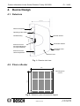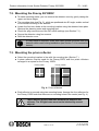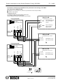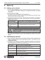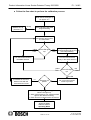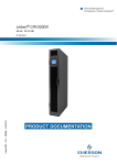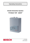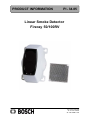
1
PRODUCT INFORMATION
PI - 34.85
Linear Smoke Detector
Fireray 50/100RV
Page
Page
11
601 -F.01U.002.705
A1.en / 29.12.2004
ST -FIR/ PRM1 / zab
Product Information Linear Smoke Detector Fireray 50/100RV
PI - 34.85
Table of Contents
1.
Product Description . . . . . . . . . . . . . . . . . . . . . . . . . . . . . . . . . . . . . . . .
3
2.
Scope of Order . . . . . . . . . . . . . . . . . . . . . . . . . . . . . . . . . . . . . . . . . . . .
3
3.
Features . . . . . . . . . . . . . . . . . . . . . . . . . . . . . . . . . . . . . . . . . . . . . . . . . .
4
4.
Device Design . . . . . . . . . . . . . . . . . . . . . . . . . . . . . . . . . . . . . . . . . . . . .
5
4.1.
Detector . . . . . . . . . . . . . . . . . . . . . . . . . . . . . . . . . . . . . . . . . . . . . . . . . . . . . . . . . . . .
5
4.2.
Prism reflector . . . . . . . . . . . . . . . . . . . . . . . . . . . . . . . . . . . . . . . . . . . . . . . . . . . . . . .
5
5.
Functional Description . . . . . . . . . . . . . . . . . . . . . . . . . . . . . . . . . . . . .
6
6.
Planning Notes . . . . . . . . . . . . . . . . . . . . . . . . . . . . . . . . . . . . . . . . . . . .
7
6.1.
Arrangement of the detectors on flat ceilings . . . . . . . . . . . . . . . . . . . . . . . . . . . .
8
6.2.
Arrangement of the detectors in a tilted roof . . . . . . . . . . . . . . . . . . . . . . . . . . . . .
9
6.3.
Arrangement of the detectors in a saddleback roof . . . . . . . . . . . . . . . . . . . . . . .
9
7.
Mounting Tips . . . . . . . . . . . . . . . . . . . . . . . . . . . . . . . . . . . . . . . . . . . . .
10
7.1.
Connections and DIP switch settings . . . . . . . . . . . . . . . . . . . . . . . . . . . . . . . . . . .
10
7.2.
Mounting the Fireray 50/100 RV . . . . . . . . . . . . . . . . . . . . . . . . . . . . . . . . . . . . . . .
12
7.3.
Mounting the prism reflector . . . . . . . . . . . . . . . . . . . . . . . . . . . . . . . . . . . . . . . . . .
12
7.4.
Connection . . . . . . . . . . . . . . . . . . . . . . . . . . . . . . . . . . . . . . . . . . . . . . . . . . . . . . . . . .
13
8.
Start-Up . . . . . . . . . . . . . . . . . . . . . . . . . . . . . . . . . . . . . . . . . . . . . . . . . .
15
8.1.
Setting up the detector . . . . . . . . . . . . . . . . . . . . . . . . . . . . . . . . . . . . . . . . . . . . . . .
15
8.2.
Aligning the detector . . . . . . . . . . . . . . . . . . . . . . . . . . . . . . . . . . . . . . . . . . . . . . . . . .
15
8.3.
System test . . . . . . . . . . . . . . . . . . . . . . . . . . . . . . . . . . . . . . . . . . . . . . . . . . . . . . . . .
17
9.
Notes for maintenance and service . . . . . . . . . . . . . . . . . . . . . . . . . .
18
9.1.
Repair . . . . . . . . . . . . . . . . . . . . . . . . . . . . . . . . . . . . . . . . . . . . . . . . . . . . . . . . . . . . . .
18
9.2.
Disposal . . . . . . . . . . . . . . . . . . . . . . . . . . . . . . . . . . . . . . . . . . . . . . . . . . . . . . . . . . . .
18
9.3.
Additional documentation . . . . . . . . . . . . . . . . . . . . . . . . . . . . . . . . . . . . . . . . . . . . .
18
10.
Technical Data . . . . . . . . . . . . . . . . . . . . . . . . . . . . . . . . . . . . . . . . . . . . .
19
11.
Appendices . . . . . . . . . . . . . . . . . . . . . . . . . . . . . . . . . . . . . . . . . . . . . . .
20
11.1. Installation protocol . . . . . . . . . . . . . . . . . . . . . . . . . . . . . . . . . . . . . . . . . . . . . . . . . . .
20
11.2. Fault diagnosis . . . . . . . . . . . . . . . . . . . . . . . . . . . . . . . . . . . . . . . . . . . . . . . . . . . . . .
21
Seite 2 von 22
601-F.01U.002.705
A1.en / 29.12.2004
ST-FIR/ PRM1/ zab
Product Information Linear Smoke Detector Fireray 50/100RV
1.
PI - 34.85
Product Description
The Fireray 50/100RV is a linear optical black and white smoke detector. The detector
is a retro- operation device, i.e. the transmitter and the receiver are located in one
housing with the control unit. A prism reflector is mounted opposite the detector and
reflects the infrared beam to the transmitter/receiver combination. If smoke penetrates
the section under surveillance, the beam to the receiver, thus the infrared signal
received, is smaller. The volume of smoke is assessed and the detector triggers a fire
alarm after a specified period of time.
The Fireray 50/100RV smoke detector comprises two components:
- Compact housing with infrared sensor, receiver and control unit
- Prism reflector.
There are two Fireray variants:
- Fireray 50RV with a range of between 5 m and 50 m
- Fireray 100RV with a range of between 50 m and 100 m.
If this documentation refers to both variants, they are combined under the designation
Fireray 50/100RV.
It is also possible to connect a key switch, which is mounted within reach, via the
RS- 485 interface. Alarm tests can be triggered using the key switch without having
to reach up to the detector. In addition, the set parameters, the detector status and the
current signals can be read and the parameters can be changed. An interface adapterand the Data Viewer software (CD) are also required.
2.
Scope of Order
Product ID
LE*
Designation
4.998.142.205
ST
Linear smoke detector Fireray 50RV
- Device with integrated transmitter, receiver and control
unit
- 1 prism reflector
- 1 test filter
- 1 connection cable with plug
4.998.142.206
ST
Linear smoke detector Fireray 100RV:
- Device with integrated transmitter, receiver and control
unit
- 4 prism reflectors
- 1 test filter
- 1 connection cable with plug
*LE = Delivery unit
The key switch, the interface adapter and the Data Viewer software (CD)
can be ordered as special merchandise.
Seite 3 von 22
601-F.01U.002.705
A1.en / 29.12.2004
ST-FIR/ PRM1/ zab
Product Information Linear Smoke Detector Fireray 50/100RV
3.
PI - 34.85
Features
Compact housing with integrated transmitter, receiver, and control unit
Detector ranges:
- Fireray 50RV
5 m to 50 m
- Fireray 100RV
50 m to 100 m
Side detection breadth of 7.5 m on both sides of the beam center line (according
to VdS max. 7 m on both sides of the beam center line)
Easy to mount; cost- effective retro operation using prism reflectors
Areas of application:
Historical buildings, churches, museums, shopping malls, factory halls,
warehouses, power plants, contaminated environments, etc.
The prism reflectors permit angle deviations up to 5 from the center line without
signal deterioration.
With a max. mounting height of 16 m, the monitored room volume can be up to
22,400 m3
Very low current consumption
Operating voltage 10 V DC to 30 V DC
Adjustable alarm thresholds/sensitivity
Alarm storage or automatic reset possible
Alarm output in the form of a potential- free, latching dry relay contact
Electronic help for detector alignment and automatic detector calibration procedure
Automatic compensation for contamination
LED indicators for:
- Alarm (red)
- Malfunction (yellow)
- Operating indicator (flashes yellow once in every 10 s)
- End of readjustment due to contamination/aging (flashes yellow once every 2 seconds)
Can be connected to the local security network via a control coupler (NSB 100)
Cross zoning possible with connection using a NBK 100 LSN and two NSB 100 LSN
Fulfills the following regulations:
- BS 5839 Part 5
- EN 54 Part 12
- VdS approval number: G 203070
Seite 4 von 22
601-F.01U.002.705
A1.en / 29.12.2004
ST-FIR/ PRM1/ zab
PI - 34.85
Product Information Linear Smoke Detector Fireray 50/100RV
4.
Device Design
4.1. Detectors
120 mm
Detector baseplate
Operating mode switch
Receiver window
210 mm
Gimbal bearing
Transmitter window
Knurled screw for
horizontal adjustment
(on right of detector)
Operating indicator LEDs
Knurled screw for
vertical adjustment
Detector cover
Fig. 1.: Detector side view
4.2. Prism reflector
100
100
ÌÌÌÌÌÌÌÌÌÌÌ
ÌÌÌÌÌÌÌÌÌÌÌ
ÌÌÌÌÌÌÌÌÌÌÌ
ÌÌÌÌÌÌÌÌÌÌÌ
ÌÌÌÌÌÌÌÌÌÌÌ
ÌÌÌÌÌÌÌÌÌÌÌ
ÌÌÌÌÌÌÌÌÌÌÌ
ÌÌÌÌÌÌÌÌÌÌÌ
ÌÌÌÌÌÌÌÌÌÌÌ
ÌÌÌÌÌÌÌÌÌÌÌ
ÌÌÌÌÌÌÌÌÌÌÌ
Mounting bore
Ğ3 mm
Fig. 2.: Reflection prism dimensional diagram
Seite 5 von 22
601-F.01U.002.705
A1.en / 29.12.2004
ST-FIR/ PRM1/ zab
Product Information Linear Smoke Detector Fireray 50/100RV
5.
PI - 34.85
Functional Description
The transmitter emits an infrared light beam (880 nm) that is focused through a lens
and invisible. The light beam is reflected by 180 by the prism reflector mounted
opposite and returned to the transmitter/receiver combination.
If the IR beam is obscured by smoke and the signal received drops below the selected
threshold value for 10 s, the Fireray triggers a fire alarm and the alarm relay closes.
The activation threshold can be adjusted to the environmental conditions. Settings
25% (sensitive), 35%, and 50% (non- sensitive) are possible.
The alarm relay has two operating modes:
With Auto Reset, the alarm relay releases again if the volume of smoke drops below
the selected alarm threshold for at least 5 s.
In Alarm memory mode, the relay remains active until it is reset. To reset, power is
dropped to the detector for at least 5s.
Slow changes to the operating states (e.g. aging of the components, contamination
of the lenses, etc.) do not cause false alarms; instead, they are balanced out by the
automatic gain control. The state of the system is compared with a default reference
value every 15 minutes and in case of deviations, compensated automatically up to
0.7 dB/h. If the readjustment limit is reached, any further signal decay will trigger a
«malfunction» (DIP switch 2 = on) or an «alarm» (DIP switch 2 = off).
If the IR beam is obscured for at least 10 seconds by more than 90% with a sharp signal
increase, the fault relay switches. The cause can be a blocking of the beam path,
detector misalignment, blocking of the reflector, etc. After eliminating the cause of the
malfunction, the fault relay is reset and the detector is reset automatically into the
detection - ready state after 5 seconds. The malfunction must be reset at the control
unit.
The detector has an alarm output in the form of a potential free, latching dry contact.
Seite 6 von 22
601-F.01U.002.705
A1.en / 29.12.2004
ST-FIR/ PRM1/ zab
PI - 34.85
Product Information Linear Smoke Detector Fireray 50/100RV
6.
Planning Notes
It is very important that the system be carefully planned and precisely adjusted, to
ensure that the detector responds as early as possible.
The response time of the system is dependent on the installation location, the volume
of smoke generated, the ceiling construction and air ventilation.
Note: Since the smoke over a fire source does not just climb vertically upwards, but
rather spreads like a mushroom cloud (depending on existing air currents and air
pockets), the breadth of the monitoring area is much greater than the diameter of the
IR beam.
According to VdS 2095 and DIN VDE 0833- 2, the number of light beam smoke
detectors must be selected so that the maximum monitoring range A specified in
the table is not exceeded.
The detectors must be distributed such that no point of the ceiling is further removed
from the beam center (horizontal distance) than is specified in column DH
The distance between two parallel beams may not be greater than the doubled
distance D DH
The center line of the monitoring beam may not be closer than 0.5 m to walls,
equipment or stored goods.
Table 1.: Distances and Monitoring Areas according to VdS
Roof pitchα
Room height
g RH
DH
A
α < 20
α > 20
DL
DL
up to 6 m
6m
1200 m2
0.3 m to 0.5 m
0.3 m to 0.5 m
more than 6 m
to 12 m
6.5 m
1300 m2
0.4 m to 0.7 m
0.4 m to 0.9 m
more than 12 m
to 16 m *)
7m
1400 m2
0.6 m to 0.9 m
0.8 m to 1.2 m
DH Greatest permissible horizontal distance of any point of the ceiling to the next-closest beam
A
Maximum monitoring range per detector (= double the product of the greatest horizontal
distance DH and the maximum permissible detector/reflector distance)
DL Distance of the detector to the ceiling
α
*)
Angle that the roof/ceiling pitch forms with the horizontal; if a roof has different pitches (e.g.
sheds), use the smallest existing pitch
With a room height of more than 12 m, it is recommended that you provide a second moni
toring level on which the detectors are arranged offset to the first monitoring level. Depends on the use and environmental conditions (e.g. rapid fire development and smoke
dissemination)
There must be a constant visual line between the detector and reflector, which may
not be interrupted by moving objects (e.g. overhead crane).
Seite 7 von 22
601-F.01U.002.705
A1.en / 29.12.2004
ST-FIR/ PRM1/ zab
Product Information Linear Smoke Detector Fireray 50/100RV
PI - 34.85
Heat accumulation under roof surfaces can hinder the travel of climbing smoke to
the ceiling. The detector must therefore be mounted below an expected heat
accumulation. This can mean that the benchmark values for DL specified in the
table must be exceeded.
ÉÉÉÉÉÉÉÉÉÉÉÉÉÉÉÉÉÉÉÉÉÉÉÉÉÉÉÉÉ
ÉÉÉÉÉÉÉÉÉÉÉÉÉÉÉÉÉÉÉÉÉÉÉÉÉÉÉÉÉ
Ceiling
Recommended height
below the ceiling
30-90 cm
Heat accumulation
IR beam
Smoke cloud
If you are uncertain about the correct position, use a smoke test to establish it.
6.1. Arrangement of the detectors on flat ceilings
2 x DH
DR
DH
DH
Fireray 50/100 RV
Prism reflectors
DL
DH
DH
2 x DH
DL
DR
Horizontal distance to detector and wall 0.5 m to 7.5 m (VdS max. 7.0 m)
Distance between two parallel beams max. 15 m (VdS max. 14 m)
Distance from the ceiling 0.3 m to 0.9 m
Range = distance between detector and reflector:
Fireray 50RV: 5 m to 50 m, Fireray 100RV: 50 m to 100 m
DH und DL are not dependent on the room height RH (see table 1.).
Seite 8 von 22
601-F.01U.002.705
A1.en / 29.12.2004
ST-FIR/ PRM1/ zab
PI - 34.85
Product Information Linear Smoke Detector Fireray 50/100RV
6.2. Arrangement of the detectors in a tilted roof
Depending on the roof pitch α and the room height RH,
the detector and the reflectors must be arranged such that the
DL
light beam in distance DL runs below the ceiling.
DL
DL
α
min. 0.5 m
max. 7m
max. 14 m
min. 0.5 m
max. 7 m
max. 14 m
6.3. Arrangement of the detectors in a saddleback roof
Depending on the roof pitch α
DL
and the room height RH, the detector
and the reflectors must be arranged
α
DL
DL
such that light beam in distance DL
runs below the ceiling.
min. 0.5 m
max. 7m
max. 14 m
max. 14 m
min. 0.5 m
max. 7 m
Depending on local rules and regulations, different distances may be
prescribed or permissible if necessary.
Seite 9 von 22
601-F.01U.002.705
A1.en / 29.12.2004
ST-FIR/ PRM1/ zab
PI - 34.85
Product Information Linear Smoke Detector Fireray 50/100RV
7.
Mounting Tips
Observe the planning notes in Section 6.
Usually, the detector and the reflector are installed at the same height and oriented
towards each other. The relatively broad angle of the IR beam eases adjustment
and guarantees reliable long- term stability.
The mounting surface for the detector must be firm and vibration- free. Metal
supports that can be influenced by heat or cold are not suitable for installation.
The detector must be installed such that sunlight and artificial light do not beam
directly into the detector’s lenses. Normal environmental light conditions have no
effect on the IR beam and the evaluation.
Mount the reflector on a solid surface at the permissible distance. Ensure that the
light beam meets the reflector on the vertical.
The reflectors must not be mounted on reflective surfaces such as glass or plain
sheet surfaces. Additional reflections lead to malfunctions.
For protection against radio interference, use a shielded cable. When you are
installing the cable, possible sources of disturbance must be circumvented and the
cable must be protected against mechanical damage.
A 6 DA mini distributor (product ID 2.798.400.302) is required for wiring.
7.1. Connections and DIP switch settings
The operating mode switches, DIP switches and terminal strips for the plug
connector (see Fig. 3.) are located on the back of the detector.
on
Mounting slots
off
DIP switch
Operating
mode switch
Plug connector
2-pin output for
optional key switches
Fig. 3.: Reverse side of detector with plug connector, operating mode switch and
DIP switch
Seite 10 von 22
601-F.01U.002.705
A1.en / 29.12.2004
ST-FIR/ PRM1/ zab
PI - 34.85
Product Information Linear Smoke Detector Fireray 50/100RV
DIP switches
The DIP switches can be accessed through the round recess in the detector base
plate.
Table 2.: Functions of the DIP switch settings
*
DIP switch settings
Function
X
X
1
2
3
4
50% threshold
X
X
OFF
OFF
35% threshold
X
X
OFF
ON
25% threshold
X
X
ON
OFF
12% threshold
(extremely sensitive, only for special applications!)
X
X
ON
ON
Alarm relay saves the alarm
OFF
X
X
X
Automatic reset 5 s after the end of the alarm criterion
ON
X
X
X
Alarm relay after end of readjustment
X
OFF
X
X
Fault relay at end of readjustment, no alarm
X
ON
X
X
The factory presets are shaded in gray.
* The recommended settings for connection to a fire panel are marked with X.
Use DIP switches 3 and 4 to set the required alarm threshold. The factory setting
is moderate sensitivity (35%) for normal environmental conditions. Select a
threshold of 50% in very dirty environments.
Use DIP switch 1 to select the «Save alarm » or «Auto Reset» function.
Select the following settings for connection to a fire panel:
- «Alarm relay saves the alarm»
- «Fault relay at end of readjustment, no alarm».
Plug connector
The plug connector can be accessed through the oval recess on the detector base
plate.
Table 3.: Pin assignment of the 8- pin connector (from left to right)
PIN number
Wire color
1
Function
Not assigned
2
blue
3
yellow
Alarm relay, work contact (NO)
4
red
Power supply +10 to +30 V DC
5
black
Power supply -
6
green
Fault relay, normally closed contact (NC)
7
white
Fault relay, center contact (COM)
8
Alarm relay, center contact (COM)
Not assigned
Seite 11 von 22
601-F.01U.002.705
A1.en / 29.12.2004
ST-FIR/ PRM1/ zab
Product Information Linear Smoke Detector Fireray 50/100RV
PI - 34.85
7.2. Mounting the Fireray 50/100RV
To make mounting easier, you can remove the detector cover by gently raising the
upper and lower edges.
The mounting slots (see Fig. 3.), which are positioned at a 90angle, enable vertical
or horizontal mounting of the detector.
Locate the four bore holes at the mounting location using the detector base plate.
Observe the planning notes and mounting tips!
Check the plug connector and the DIP switch settings (see Section 7.1.).
Secure the detector using four screws.
Refit the detector cover.
If a key switch is required, a two- wire cable should be routed from the
detector within reach during installation (see Section 7.4. for connection
details).
7.3. Mounting the prism reflector
Select the mounting location in line with the mounting tips (Section 7.).
A prism reflector must be used for the Fireray 50RV, and four prism reflectors
arranged in a square for the Fireray 100RV.
ÌÌÌÌÌ
ÌÌÌÌÌ
ÌÌÌÌÌ
ÌÌÌÌÌ
Fireray 50RV
ÌÌÌÌ
ÌÌÌÌÌ
ÌÌÌÌ
ÌÌÌÌÌ
ÌÌÌÌ
ÌÌÌÌÌ
ÌÌÌÌ
ÌÌÌÌÌÌÌÌÌ
ÌÌÌÌÌ
ÌÌÌÌ
ÌÌÌÌÌ
ÌÌÌÌÌÌÌÌÌ
ÌÌÌÌÌÌÌÌÌ
Fireray 100RV
Fig. 4.: Prism reflectors
Each reflector is secured using two mounting bores. Arrange the four reflectors for
the Fireray 100RV such that there are no mounting holes in the center (see Fig. 4.).
There must be a free visual line between the detector and
reflector. The IR light beam must not be blocked by moved
objects!
Seite 12 von 22
601-F.01U.002.705
A1.en / 29.12.2004
ST-FIR/ PRM1/ zab
PI - 34.85
Product Information Linear Smoke Detector Fireray 50/100RV
7.4. Connection
Connection of a Fireray 50/100RV using a NSB100 LSN at the fire panel
1
Bridges Br1, Br2 in position 2-3
2
Contacts in open position
NSB 100 LSN
I1 NLT1
Configuration for LSN:
Parameterize the NSB in the control panel to
control output KA1-KA2/KR-R-RR and
“Control with Fireray”.
VII1
I3 -U
VII2
I4 +U
LSN
II1 NLT2
Fireray 50/100 RV
Br 1
II2 ⊥
on
DIP switch
(recommended settings)
1
2
3
1
II3 -U
off
Br 2
II4 +U
1
2
3
III1
Operating mode
switch
MALFUNCTION
Power supply 10 - 30
V
ALARM
+ -
III2
IV1 RR
IV2 R
2
V1 KR
COM
NC
NO
COM
Output
for key switch
(optional)
SA
SB
I2 ⊥
V2 KA1
V3 KA2
3K3
RE
680 Ω
VI1
VI2
UEB
gn
rd
bl
UEA
wh
bl
ye
Operating mode switches:
Prism Targeting
Alignment Mode
Operating Mode
6 DA mini
distributor
-U
+U
-U
DIP switch:
Functions, see table (below)
I3
+U
I4
NSB 100
(if voltage drop < 6 V)
EV 24 V - 24 V
(if voltage drop > 6 V)
DIP switch setting
*
X
X
DIP switch functions
1
2
3
4
50% threshold
X
X
OFF
OFF
35% threshold
X
X
OFF
ON
25% threshold
X
X
ON
OFF
Reserved for later use
X
X
ON
ON
Alarm relay saves the alarm
OFF
X
X
X
Automatic reset 5 s after the end of the alarm criterion
ON
X
X
X
Alarm relay after end of readjustment
X
OFF
X
X
Fault relay at end of readjustment, no alarm
X
ON
X
X
The factory presets are shaded in gray.
* The recommended settings for connection to a fire panel are marked with X.
Seite 13 von 22
601-F.01U.002.705
A1.en / 29.12.2004
ST-FIR/ PRM1/ zab
PI - 34.85
Product Information Linear Smoke Detector Fireray 50/100RV
Connection of two Fireray 50/100RV to fire panel with cross zoning via an NBK
100 LSN and two NSB100 LSNs
1
Bridges Br1, Br2 on the NSB 100 in position 2-3 (see connection of one Fireray 50/100RV)
2
Contacts in open position
Configuration for LSN:
Parameterize the NSB in the control panel to control output
KA1-KA2/KR-R-RR and “Control with Fireray”.
Observe assignment to detector groups/detectors (see example).
NBK 100 LSN
Fireray 50/100 RV
Parameterize, e.g. to 127/1
VI1
DIP switch
(recommended settings)
Line 1
150/1 cross zoning with
500, current trigger
criterion
Line 2
500/1 cross zoning
with 150, current
trigger criterion
VI2
Operating mode
switch
MALFUNCTION
Power supply 10 - 30
V
ALARM
2
3k92
820
bl
V2
COM
NC
-
+
NO
COM
Output
for key switch
(optional)
V1
ye
rd
bl
gn
NSB 100 LSN
wh
Parameterize, e.g. to 127/2
V1 KR
V2 KA1
Parameterize, e.g. to
V3 KA2
KA1-KA2-KR-150/2
6 DA mini
distributor
1
Fireray 50/100 RV
DIP switch
(recommended settings)
Operating mode
switch
NSB 100 LSN
Parameterize, e.g. to 127/3
V2 KA1
Parameterize, e.g. to
V3 KA2
KA1-KA2-KR-500/2
1
3k92
bl
2
COM
NC
820
rd
ye
-
+
NO
COM
bl
MALFUNCTION
Power supply 10 - 30
V
ALARM
Output
for key switch
(optional)
V1 KR
gn
wh
6 DA mini
distributor
-U
+U
-U
I3
+U
I4
NSB 100
(if voltage drop < 6 V)
Seite 14 von 22
EV 24 V - 24 V
601-F.01U.002.705
A1.en / 29.12.2004
ST-FIR/ PRM1/ zab
PI - 34.85
Product Information Linear Smoke Detector Fireray 50/100RV
8.
Start- Up
8.1. Setting up the detector
Start the «Prism Targeting»mode by moving the operating mode switch (see Fig. 3.)
up (if the detector is mounted vertically) or to the right (if the detector is mounted
horizontally).
Connect the power supply.
The detector runs in initialization mode for approx. 5 s.
As soon as the detector is ready for use, the red LED flashes (once with the Fireray
50RV and twice with the Fireray 100RV).
Now direct the detector at the prism, using the two knurled screws, until optimum
adjustment is confirmed by a steady yellow LED light. The following LED displays
support detector set- up:
Yellow LED display
Detector status in «Prism Targeting» operating mode
off
No signal at receiver
Flashes
-> Flashing frequency increasing
Signal is received
-> The faster the flashing, the stronger the signal!
Steady light
Optimum alignment achieved
The signal must only move from the reflector to the receiver,
under no circumstances must it move to other light sources or
reflective surfaces!
Cover the prism reflector with a non- reflective material to check. The LED must not
be lit. If the yellow LED does not go out, this indicates that a reflector is incorrectly
aligned.
8.2. Calibrating the detector
Once the optimum detector set- up has been achieved, set the operating mode
switch to the center position without displacing the detector. The detector is now in
(«Alignment Mode»).
The detector runs through an automatic configuration procedure to optimize the
transmission power and the receiver sensitivity. The following detector statuses
may be displayed by the LEDs during this procedure:
LED displays
Detector statuses in «Alignment Mode»
Flashing red
Receiver input signal too strong, the transmission power will be reduced. Wait until the LED goes out (max. 20 s).
Steady yellow light
No signal is being received. Switch back to «Prism Targeting» mode
and repeat the detector set-up.
Flashing yellow
The receiver is receiving a weak signal, the transmission power will
automatically be increased.
off
Transmission power and receiver gain are optimum.
Flashing red and yellow
Automatic calibration in progress.
Seite 15 von 22
601-F.01U.002.705
A1.en / 29.12.2004
ST-FIR/ PRM1/ zab
PI - 34.85
Product Information Linear Smoke Detector Fireray 50/100RV
Follow the flow chart to perform the calibration process:
Switch center Alignment
Mode Yellow LED lights up
for approx. 5 s
No signal: back to
detector set-up
(Section 8.1.)
Steady
yellow LED
Wait until both LEDs have
stopped flashing
Turn the knurled screws in
one direction and monitor
the LED status
yellow
LED
Which LED lights
up?
red
LED
Stop turning the knurled
screw and wait until the red
LED stops flashing
Turn the knurled screw
slowly in the same direction
Turn the knurled screw in
the other direction
yellow
LED
Which LED lights
up?
red
LED
No LED
Repeat the
procedure for the other
detector axis with the
second knurled screw
no
Both axes adjusted?
Do not turn the knurled
screw any further
y
e
Check optimum setting:
s
Yellow LED lights up:
1. With gentle pressure from top/bottom/left/
right on the detector housing.
2. Each time the knurled screws are moved.
Exit the
Alignment Mode
Switch at bottom:
Operating Mode
Seite 16 von 22
601-F.01U.002.705
A1.en / 29.12.2004
ST-FIR/ PRM1/ zab
Product Information Linear Smoke Detector Fireray 50/100RV
PI - 34.85
When the calibration procedure is complete, move the operating mode switch (see
Fig. 3.) to the bottom (if the detector is mounted vertically) or to the left (if the
detector is mounted horizontally). The detector is now in «Operating Mode».
The detector runs a calibration test for approx. 60 s. If the yellow LED lights up as
a steady light after the test, you must repeat the detector alignment and calibration
procedures (see Sections 8.1. and 8.2.).
If a detector alarm is reset in normal mode by a disruption to the power
supply, the detector automatically runs a calibration test. If the test is
failed, the detector remains in the alarm position. If the test is positive,
the yellow LED goes out, the fault relay is reset and the detector is
returned to normal mode.
In normal mode, the yellow LED flashes every 10 s.
8.3. System test
The «Alarm» and «Malfunction» functions must be checked before final start - up.
Alarm test
Hold the test filter in front of the receiver lens (upper or right- hand part of detector).
Select a volume of smoke slightly greater than the threshold set for the detector (see
Section 7.1.). Make sure that you do not also cover the transmitter -lens.
After approx. 10 s, the red LED must light up and the alarm relay must close.
With the «Save alarm» detector setting (DIP switch 1 «off»), there must be a reset
at the control panel or the power supply must be disrupted for at least 5 s.
With the setting «Auto Reset» setting (DIP switch 1 «on»), the alarm is reset
automatically if the volume of smoke falls below the selected alarm threshold for at
least 5 s.
Fault test
Cover the reflector with a non- reflective material.
After approx. 10 s, the yellow LED must light up and the fault relay must open. As
soon as the obstruction is removed, the detector returns to normal mode
automatically after approx. 2 s.
Seite 17 von 22
601-F.01U.002.705
A1.en / 29.12.2004
ST-FIR/ PRM1/ zab
Product Information Linear Smoke Detector Fireray 50/100RV
9.
PI - 34.85
Tips on Maintenance and Service
For maintenance and inspection work on danger detector systems, in Germany
the regulations of DIN VDE 0833 apply, which refer to the maintenance interval
according to the manufacturer’s instructions.
Bosch ST recommends a functional and visual inspection at least once a year.
Maintenance and inspection work should be carried out regularly and by trained
personnel.
9.1. Repair
In the event of a defect, the entire device is exchanged.
9.2. Disposal
Defective devices should be disposed of according to the legal requirements.
9.3. Additional Documentation
For those with access rights, the Bosch ST ExtraNet at
www.boschsecurity.com/emea/fire
contains the most up- to - date product information and the installation
manual supplied with the device can be downloaded in PDF format.
Seite 18 von 22
601-F.01U.002.705
A1.en / 29.12.2004
ST-FIR/ PRM1/ zab
Product Information Linear Smoke Detector Fireray 50/100RV
PI - 34.85
10. Technical Data
Operating voltage
10 V DC . . . 30 V DC
Current consumption:
- in standby mode
- in alarm/malfunction
< 4 mA @ 24 V
< 15 mA
Reset control by power disruption
Alarm relay
Fault relay
Permissible distance between the detector and the
prism reflector:
- Fireray 50R
- Fireray 100R
Optical wavelength
>5s
Open contact, potential free
(2 A @ 30 V DC)
Break contact element,
potential - free
(2 A @ 30 V DC)
5 m to 50 m
50 m to 100m
880nm
Adjustable alarm threshold values
2.50 dB (25%)
3.74 dB (35%)
6.02 dB (55%)
Detector $0.8
Prism reflector $5.0
Axial deviation tolerance
(at 35% sensitivity)
Operating temperature
- 30C . . . +55C
Protection type
IP 50
Dimensions (W x H x D)
126 x 210 x 120 mm
Weight
670 g
Housing:
- Color
- Material
light gray/black
ABS, non- flammable
VdS ID number
G 203 070
Seite 19 von 22
601-F.01U.002.705
A1.en / 29.12.2004
ST-FIR/ PRM1/ zab
PI - 34.85
Product Information Linear Smoke Detector Fireray 50/100RV
11.
Appendices
11.1. Installation protocol
Installation company:
Type of object:
Installation location:
Installation date:
Total number of all linear detectors:
Detector version:
Detector – reflector distance:
_________ m
Distance of the detector axes to one
another
_________ m
Mounting height
_________ m
Fireray 50RV
Fireray 100RV
Mounting surface (e.g. masonry/reinforced concrete/steel beams/wood/etc.)
Serial number(s):
Reflector size:
Supply voltage:
_________ V
Correct mechanical adjustment of
transmitter (when gentle pressure is
applied to the detector housing from
the left/right/top/bottom, the yellow LED
lights up initially):
yes
no
Alarm triggered with absorption film
35% - 50% tested:
yes
no
Fault triggered by disruption of IR
beam tested:
yes
no
1 x (10 x 10 cm)
4 x (20 x 20 cm)
DIP switch settings:
1
2
3
4
on
off
Comments (environmental conditions, e.g. dust, humidity, temperature etc.)
Installation tested on: ____________
by: ___________________________
Seite 20 von 22
601-F.01U.002.705
A1.en / 29.12.2004
ST-FIR/ PRM1/ zab
Product Information Linear Smoke Detector Fireray 50/100RV
PI - 34.85
11.2. Fault diagnosis
Fault indicator
Fault LED
illuminated
permanently
Possible cause
Action
Beam path blocked by an obstacle
Check and/or ensure free visual line
in the area between the detector and
the reflector.
Reflector is contaminated/covered/
has fallen down.
Check the status of the reflector and
clean it if necessary.
Supply voltage too low.
Measure supply voltage directly at detector.
Mode sliding switch in upper position
(«Direct»)
Set the switch to «Operation» and
wait until the 60 s activation routine is
complete.
Detector set-up changed on switching to «Operation».
When operating the sliding switch
following the correct adjustment,
make sure that the setting is not
changed.
The limit of automatic gain control has Clean detector lens and reflector and
been reached
correct mechanical adjustment!
Fault LED flashes
Alarm LED
illuminated
permanently
No fault message
when IR beam is
disrupted
Alarm triggered
when IR beam is
disrupted
Triggering of false
alarms
«MODE Switch» sliding switch in up- Align detector vertically and horizontally until the fault LED is permanently
per position («Direct») and incomplete detector set-up
illuminated. Then continue using fine
adjustment (switch in center position)!
DIP switch 1 at OFF
(«Save alarm »),
the alarm display remains saved
Reset the detector by disrupting the
supply voltage for at least 5 s or
select «Reset» on the fire panel
Beam path (partially) blocked by an
obstacle
Ensure a free visual line in the area
between the detector and the reflector!
Detector receives partial IR signal,
e.g. via reflective surfaces near the
beam axis.
Cover reflector with a dark material to
test! Check detector’s range of vision
for reflective objects!
An object placed in the beam path for
testing has acted as the reflector.
For testing, use a non-reflective
material, maintain a greater distance
to the detector, cover the reflector as
directly as possible.
Sensitivity to existing environmental
conditions set too high
Set a less sensitive alarm threshold
(DIP switches 3 and 4):
normal= 35%, less sensitive= 50%
Seite 21 von 22
601-F.01U.002.705
A1.en / 29.12.2004
ST-FIR/ PRM1/ zab
Bosch Security Systems
Robert -Koch -Str. 100
D-85521 Ottobrunn
Info -Service
Telephone: +49 89 6290 - 1039
Fax:
+49 89 6290 - 1039
www.boschsecurity.com
[email protected]
Page 22 of 22