1
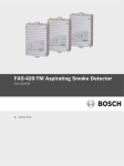
Operating Instructions
Smoke Extraction System
TITANUS TOP · SENS®
F.01U.003.292
A3.en / 27.04.2006
ST-FIR / PRM1 / zab
TITANUS TOP · SENS®
Table of Contents
Table of Contents
0
General Remarks
5
0.1
Introduction
5
0.2
Safety Instructions
5
0.3
Warranty
6
0.4
Copyright
6
1
Product Description
7
1.1
Properties of the TITANUS TOP · SENS® Smoke Extraction System 7
1.2
Areas of Application
2
Technical Description
12
2.1
System Description
12
2.1.1
Function
13
®
2.2
TITANUS TOP · SENS and Accessories
16
2.2.1
Overview
16
®
2.2.2
TITANUS TOP · SENS Basic Device
17
2.2.3
DIAG Diagnostic Software
19
2.2.4
Device Mounting
20
2.3
Pipe System
21
2.3.1
Suction Openings
23
2.3.2
Air Return for Pressure Areas and Atmospheric Loads
25
2.3.3
Water Separator for Humid Areas
26
2.3.4
Detonation Safety Barrier for Areas in Danger of Explosion
27
2.3.5
Scope of Delivery: Smoke Extraction System
28
3
Technical Data
30
3.1
TITANUS TOP · SENS®
3.2
BOSCH
9
30
®
Pipe System TITANUS TOP · SENS
-1-
32
ST-FIR / PRM1 / A3.en
TITANUS TOP · SENS®
Table of Contents
4
Planning
33
4.1
Regulations
33
4.2
Pipe System
34
4.3
Airflow Monitoring
36
4.4
Specifying the Sensitivity
38
4.5
Planning Boundaries
40
4.6
Standard Planning
41
4.6.1
Planning of the Detection Points
41
4.6.2
Standard Pipe Planning
41
4.6.2.1
I- Pipe System
41
4.6.2.2
U- Pipe System
43
4.6.2.3
Double-U-Pipe System
45
4.6.3
Planning with Long Pipe Feed Lines
46
4.6.4
Simplified Pipe Planning
47
4.6.4.1
I- Pipe System
47
4.6.4.2
U- Pipe System
48
4.6.4.3
Double-U-Pipe System
49
4.6.5
BOSCH
Pipe Planning for Single-Hole Monitoring
50
4.6.5.1
I- Pipe System
50
4.6.5.2
U- Pipe System
52
4.6.5.3
Double-U-Pipe System
54
4.7
Planning for Forced Airflow
56
4.8
Power Supply
60
5
Installation TITANUS TOP · SENS®
62
5.1
General Remarks
62
®
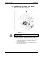
5.2
Opening the TITANUS TOP · SENS Smoke Extraction System
63
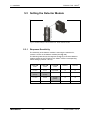
5.3
Setting Detector Module
64
5.3.1
Response Sensitivity
64
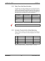
5.3.2
Delay Time of the Alarm Activation
65
5.3.3
Activation Threshold of the Airflow Monitoring
65
5.3.4
Delay Time of the Airflow Malfunction
66
5.3.5
Malfunction Display
66
5.3.6
LOGIC · SENS
66
-2-
ST-FIR / PRM1 / A3.en
TITANUS TOP · SENS®
BOSCH
Table of Contents
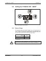
5.4
Setting the TITANUS TOP · SENS®
67
5.4.1
Blower Voltage
67
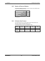
5.4.2
Number of Detector Modules
68
5.4.3
Collective Fault Contact
68
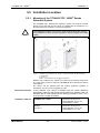
5.5
Installation Location
69
®
5.5.1
Mounting of the TITANUS TOP · SENS Smoke Extraction System 69
5.5.2
Connecting the Suction Pipe
71
5.6
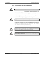
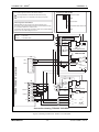
Connection to the Fire Panel
72
5.6.1
LSN Configuration with WinPara
75
5.6.2
LSN Configuration with RPS (Remote Programming Software)
75
5.7
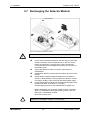
Exchanging the Detector Module
76
5.8
Vibration Absorbers
77
5.9
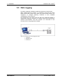
Data Logging
78
6
Installation of the Pipe System
79
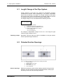
6.1
Length Change of the Pipe System
80
6.2
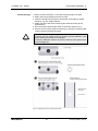
Patented Suction Openings
80
6.3
Monitoring with Forced Airflow
82
6.3.1
Detection at Intake and Exhaust Openings
82
6.3.2
Detection in the Bypass
82
6.4
Air Filter
83
6.4.1
Installation of Filter Box
83
6.4.2
Changing the Filter in the Filter Box
84
6.5
Air Return
85
6.6
3-Way Ball Valve
86
6.7
Water Separators
88
6.8
Detonation Safety Barrier
89
6.9
Test Adapter
90
-3-
ST-FIR / PRM1 / A3.en
TITANUS TOP · SENS®
Table of Contents
BOSCH
7
Start-Up
91
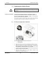
7.1
Calibrating the Airflow Sensor
92
7.1.1
Air Pressure-Independent Calibration
92
7.1.2
Air Pressure-Dependent Calibration
93
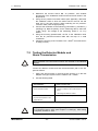
7.2
Testing the Detector Module and Alarm Transmission
94
7.3
Testing Malfunction Transmission
95
7.4
Testing the Airflow Monitoring
95
7.5
Functional Test of the TITANUS TOP · SENS®
96
7.5.1
Preparations for the Functional Test
96
7.5.2
Execution of the Functional Test
97
8
Maintenance
99
8.1
Visual Check
99
8.2
Blink Code Table
99
8.3
Detector Module and Alarm Transmission
99
8.4
Pipe System
100
8.5
Checking the Airflow Sensor Calibration
101
8.6
Airflow Monitoring
103
8.7
Malfunction Transmission
103
8.8
Maintenance Intervals
103
9
Appendices
9.1
Air Pressure-Correction Tables
105
9.2
Test Protocol
108
104
-4-
ST-FIR / PRM1 / A3.en
TITANUS TOP · SENS®
General Remarks - 0
0 General Remarks
0.1 Introduction
This manual describes the following smoke extraction systems:
TITANUS TOP · SENS® TT-1 and TITANUS TOP · SENS® TT-2. These
systems may be used exclusively for early fire detection. Since these smoke
extraction systems are devices in a single series, the designation
TITANUS TOP · SENS® in the present operating instructions refers to
both types (TITANUS TOP · SENS® TT-1 and TT-2) of the series. Devicespecific characteristics of one type are explicitly mentioned.
All works may be carried out by qualified personnel only!
BOSCH Sicherheitssysteme GmbH, called BOSCH in the following,
assumes no liability for damage and malfunctions that arise from the
disregarding of this manual.
0.2 Safety Instructions
The following symbols indicate points in this manual that require
particular attention in order to prevent damage and guarantee smooth
operation.
This symbol warns against behavior which, if disregarded, could cause
property damage.
WARNING
This symbol warns against behavior which, if disregarded, could cause
operational malfunctions.
NOTE
With attention to this symbol, you can achieve operational improvements.
TIP
BOSCH
-5-
ST-FIR / PRM1 / A3.en
TITANUS TOP· SENS ®
0 – General Remarks
0.3 Warranty
This manual is subject to technical changes without prior notice and
makes no claim to completeness.
Only our “delivery and installation conditions” apply. Warranty and liability
claims in case of personal injury and property damage cannot be
asserted if they are based on one or more of the following causes:
• Insufficient attention to the instructions with respect to planning,
installation of the smoke extraction system, installation of the pipe
system, start-up, and maintenance
• Use of the smoke extraction system not in accordance with the
regulations
• Insufficient maintenance of wearing parts
• Faulty repairs
• Arbitrary constructional changes to the smoke extraction system
• Acts of God
0.4 Copyright
The copyright for this technical manual remains with BOSCH.
This manual is intended exclusively for installers and their employees.
Reprinting this manual, in full or in part, is not permitted. The duplication
or dissemination of this manual in any form may only occur with the
written permission of BOSCH.
BOSCH
-6-
ST-FIR / PRM1 / A3.en
TITANUS TOP · SENS®
Product Description - 1
1 Product Description
1.1 Properties of the TITANUS TOP · SENS®
Smoke Extraction System
The TITANUS TOP · SENS® smoke extraction system can be used for
space and equipment protection as well as for monitoring air-conditioning
units and air-conditioning ducts.
LSN-compatible
It can be connected directly to the local security network (LSN).
Sensitivity
The device has a response sensitivity of up to 0.08 %/m, 0.025 %/m or
0.005 %/m light obscuration. Additional sensitivities can be set stepwise
depending on the area of application. With the new high-power light
source technology, a broad detection spectrum including all normal types
of fire is achieved. (Device sensitivity, sensitivity of detection points,
collective effect, see Chapter 4.4.)
If two TITANUS TOP · SENS® TT-2 detector modules are used, twice the
space can be monitored.
The device has three alarm levels per detector module: the info-, preand fire alarm.
LOGIC · SENS
The intelligent signal processing LOGIC · SENS distinguishes between
deception variables and fire events in order to prevent false alarms.
Secure Airflow
Monitoring
Patented Suction
Openings
BOSCH
Analogous to point-type smoke detectors, which are monitored
electronically for wire breaks and short circuits, highly-sensitive and
dependable airflow monitoring is required for smoke extraction systems.
The airflow sensors used in the TITANUS TOP · SENS® reliably
recognize malfunctions such as breaks in pipes or the blockage of
suction openings.
The airflow monitoring is temperature-compensated and can be set
depending on the air pressure.
Depending on the planning, the suction openings of the pipe system
require clearly-defined bore diameters. These precise suction openings
are created using patented suction-reducing film sheets, marking tape,
and clips, which not only permit comfortable installation, but also prevent
“whistling“ auxiliary noises. Another advantage is the quick and easy
detection and checking of the suction opening diameters.
-7-
ST-FIR / PRM1 / A3.en
TITANUS TOP · SENS®
1 – Product Description
Point-Type Detector
Planning
Diagnosis
Selection of Blower
Voltage
BOSCH
The system’s suction points can be equated with point-type smoke
detectors. The monitoring surfaces can therefore be planned in
accordance with the respectively-valid national regulations.
For maintenance and service, there is a system available with diagnostic
software that enables quick and comfortable error containment.
The reading-out of the current and saved device states occurs via cable
data transmission to the PC.
By plugging in the blower jumper, the blower voltage for special planning
can be increased from 6.9 V to 9 V. This causes an increase in the airtransport speed and thus an abbreviation of the detection time.
-8-
ST-FIR / PRM1 / A3.en
TITANUS TOP · SENS®
Product Description - 1
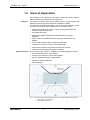
1.2 Areas of Application
Principle
The TITANUS TOP · SENS® is a fire alarm system that can be used for
early fire detection in spaces and for equipment.
Air samples are taken from the monitoring area by a pipe system with
defined suction borings and supplied to the detector module.
It is especially well-suited for areas in which point-type detectors cannot
be used or can only be used conditionally. Such areas include:
• areas that are difficult to access, in which point-type detectors are
difficult to install and maintain,
• air-conditioned areas,
• areas whose height is greater than that allowed for point-type
detectors,
• areas in which for aesthetic reasons point-type detectors are not
desired,
• areas in which electromagnetic fields are influential,
• areas that are subject to high or low temperatures,
• areas with air pollution where filter elements are required,
Space Protection
• areas that must be protected against vandalism.
The TITANUS TOP · SENS® is suitable for monitoring spaces including
• those with double floors, false ceilings,
• tunnels, ducts, difficult-to-reach hollow spaces,
• storage, high-rack storage, elevator shafts,
• museums, cultural institutions,
• freezer storage.
®
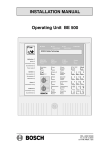
Fig. 1.1: Principle of space monitoring with TITANUS TOP · SENS smoke extraction system
1
2
BOSCH
Pipe system room monitoring
Pipe system double floor
-9-
ST-FIR / PRM1 / A3.en
TITANUS TOP · SENS®
1 – Product Description
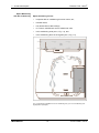
Space Monitoring
with Air Conditioning
Space monitoring occurs:
•
in spaces with air conditioning for server rooms, etc.,
•
in blower ducts,
•
over double floors, false ceilings,
•
in IT rooms, e-distributor rooms, transformer cells,
•
in air-conditioning units (see 1, Fig. 1.2), and
•
in air-conditioning ducts in the bypass (see 2, Fig. 1.2).
Fig. 1.2: Monitoring possibilities for an air-conditioning unit (1) or an air-conditioning duct
(2) (depiction of principle)
BOSCH
- 10 -
ST-FIR / PRM1 / A3.en
TITANUS TOP · SENS®
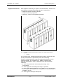
Equipment Protection
Product Description - 1
With equipment monitoring, an object is monitored directly. These can be
unventilated or mandatorily-ventilated devices or cabinets, e.g.
• distributor cabinets, switching cabinets
• telephone-switching equipment
• measuring, control, and regulation equipment.
®
Fig. 1.3: Principle of equipment monitoring with TITANUS TOP · SENS smoke extraction
system
1
cracking
The TITANUS TOP · SENS® smoke extraction system can also be used
for early fire detection in spaces with special air conditioning.
Thanks to its high sensitivity, expensive goods and equipment can be
monitored reliably. The TITANUS TOP · SENS® is therefore also
especially well-suited for areas of application with difficult detection
conditions,
• in which early intervention is necessary due to high value
concentration,
• in which equipment must always be ready for operation,
• in which highly-sensitive detection is necessary (e.g. in areas where,
due to built-in filter elements, a small portion of smoke particles is
available in the air),
• in which high air-exchange rates prevail.
BOSCH
- 11 -
ST-FIR / PRM1 / A3.en
TITANUS TOP · SENS®
2 – Technical Description
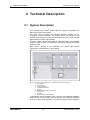
2 Technical Description
2.1 System Description
The TITANUS TOP · SENS® smoke extraction system is composed of a
basic device and a pipe system.
The basic device contains the sensitive detector module for the
recognition of smoke aerosols, the suction unit for the transport of air
samples to the detector module and the airflow sensor for monitoring the
pipe system for breaks and blockage.
The pipe system consists essentially of pipe and fittings. The standard
model is made of PVC. For equipment monitoring, halogen-free pipes
should be used.
Each suction opening in the TITANUS TOP · SENS® pipe system
represents a ceiling detector in the planning.
®
Fig. 2.1: Overview of the TITANUS TOP · SENS smoke extraction system
1
2
3
4
5
6
7
8
9
Pipe system
Air sampling
Suction openings
TITANUS basic device
Housing
Detector Module incl. air flow sensor
Suction unit
Air outlet
External detector alarm display
To guarantee secure operation even under the most difficult conditions
(clean rooms, recycling area), there are numerous accessories available,
such as air filters, water separators, and external detector alarm displays.
BOSCH
- 12 -
ST-FIR / PRM1 / A3.en
TITANUS TOP · SENS®
2.1.1
Technical Description - 2
Function
Air samples are taken from the area to be monitored using the suction
unit via a pipe system with defined suction openings and supplied to the
sensitive detector module (see Fig. 2.1).
Detector Module
Depending on the response sensitivity of the detector module used
(optionally up to 0.8%/m, 0.25 %/m or 0.05 %/m light obscuration), the
TITANUS TOP · SENS® triggers an alarm if the corresponding light
obscuration is reached. Four different alarm thresholds can be set: Three
alarm levels (info-, pre- and fire alarm) are displayed via the alarm LEDs
on the device and transmitted to a connected fire panel. With the
TITANUS TOP · SENS® TT-2 two alarm levels per detector module are
transmitted to the BOSCH fire panels.
The alarm thresholds and the display and transmission of malfunctions
can be supplied with different delay times (see Chapter 5.3).
Alarm messages are saved and are reset after the cause has been
eliminated.
With the TITANUS TOP · SENS® TT-2 the two integrated detector
modules allow the monitoring of two areas. When monitoring only one
area, a two-detector dependency can be implemented. A two-zone
dependency is only possible if connected to the Modular Fire Panel
FPA-5000.
LOGIC · SENS
Monitoring
Detector Module
Airflow Monitoring
BOSCH
Using a switch, the intelligent signal processing LOGIC · SENS can be
activated or deactivated on the TITANUS TOP · SENS® detector module.
LOGIC · SENS makes a comparison of the measured smoke level with
known disturbance values and decides between alarm and deception.
Each detector module is monitored for soiling, malfunction of the signal,
and removal. Soiling of the detector module has no effect on its
sensitivity. A malfunction is displayed by the malfunction LED on the
TITANUS TOP · SENS® and transmitted via the integrated coupler (a fire
control interface and fire interface) to the fire panel. Malfunctions due to
brief environmental fluctuations can be eliminated with a time-delayed
setting.
An airflow sensor checks the connected pipe system for breaks and
blockage. The airflow sensor can – depending on the construction of the
pipe system (see Chapter 4 “Planning“) – detect at least a blockage of
50% of the suction openings up to complete blockage and a break in the
pipe system, which has as a consequence the loss of 50% of the suction
openings. On failure of the blower, the airflow in the pipe system is
interrupted, which causes a blockage notification. The airflow monitoring
is temperature-compensated and can be set depending on the air
pressure.
- 13 -
ST-FIR / PRM1 / A3.en
TITANUS TOP · SENS®
2 – Technical Description
After the expiration of a delay time that can be programmed via a switch,
the malfunction is displayed on the smoke extraction system and the
message is transmitted via the integrated coupler if necessary to the fire
panel. The thresholds of the monitoring window can be adjusted to the
environmental conditions (see Chapter 4 “Planning“).
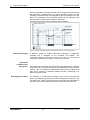
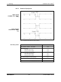
The principal signal process of the airflow sensor displays
Fig. 2.2: Example of the signal process of the airflow sensor in case of malfunctions
Malfunction Display
Blink Code
for Malfunction
Recognition
Resetting by Fire Panel
BOSCH
A detector module or airflow malfunction generates a malfunction
message that is displayed on the TITANUS TOP · SENS®. The
malfunction display can be set to save or not save. If a fire panel is
connected, the malfunction display must be set to not save.
The malfunctions and particular device states are displayed by 3 different
blink codes via an LED on the electronics motherboard of each detector
module. Thus it is possible to differentiate quickly among malfunctions
that can be caused by a defective detector module, a blockage, or a
break in the pipe system.
The resetting of a malfunction message occurs via the connected fire
panel. The integrated couplers (fire control interface/fire interface) in the
TITANUS TOP · SENS® ensure that alarm and malfunction messages on
the device are reset simultaneously with the reset of the detector line.
- 14 -
ST-FIR / PRM1 / A3.en
TITANUS TOP · SENS®
Technical Description - 2
Relay Output
For the existing alarm threshold and for the collective malfunction , the
TITANUS TOP · SENS® has a potential-free switching contact. Thus the
smoke extraction system can be connected to all current BOSCH fire
panels.
Airflow Calibration
Thanks to the automatic airflow calibration the start-up of the
TITANUS TOP · SENS® is simplified considerably. The initialization phase
is executed optionally depending on the air pressure or independent of it.
To set the TITANUS TOP· SENS® to the characteristic airflow for the pipe
network, the airflow-init process is executed. This must be executed for
each device once at the beginning after installation, after each replanning of the pipe system, and after changing the blower voltage, so
that the device can acquire and save the airflow characteristic for the
pipe network.
Pipe System
BOSCH
A pipe system up to a total length of 180 m with a maximum of 24 suction
points can be connected to the TITANUS TOP · SENS® TT-1
2 pipe systems can be connected to the TITANUS TOP · SENS® TT-2.
The entire pipe system then has a total length of 2 x 180 m and a
maximum number of 2 x 24 suction points.
- 15 -
ST-FIR / PRM1 / A3.en
TITANUS TOP · SENS®
2 – Technical Description
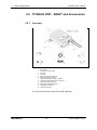
2.2 TITANUS PRO · SENS® and Accessories
2.2.1
Overview
Fig. 2.3: Overview of the TITANUS TOP · SENS
1
2
3
4
5
6
7
8
9
10
11
12
®
Pipe system
Fire panel / power supply
Air return
Fire cable
Vibration absorbers (optional)
Device mounting (optional)
Cable feed through (1 x M20, 2 x M25)
Connection pieces (M20, M25), (optional)
Diagnostic cable (optional)
Diagnostic software (optional)
Test adapter (optional)
Test pipe (optional)
The components marked “optional” are sold separately.
BOSCH
- 16 -
ST-FIR / PRM1 / A3.en
TITANUS TOP · SENS®
2.2.2
Technical Description - 2
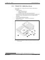
TITANUS TOP · SENS® Basic Device
The TITANUS TOP · SENS® basic device consists of the following
components:
•
plastic housing
• plastic connection pieces
• integrated air-return pipe
• connection for pipe with 25 mm exterior diameter
• sensitive detector module with the newest technology according to the
principle of optical scattered-light detector with integrated airflow
monitoring
• suction unit with optimized air supply
• optical displays for alarm1, malfunction, and operation
• diagnostic interface
®
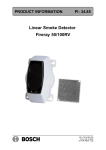
Fig. 2.4: Displays and connections for TITANUS TOP · SENS (for explanations, see table
on the next page)
1
BOSCH
®
for TITANUS TOP · SENS 2 : optical display for Alarm 1 and Alarm 2
- 17 -
ST-FIR / PRM1 / A3.en
TITANUS TOP · SENS®
2 – Technical Description
®
®
Fig. 2.5: Displays: TITANUS TOP · SENS TT-1 (first) and TITANUS TOP · SENS TT-2
(second), for explanations, see Number 1 in the table
TITANUS TOP · SENS®
Fig. 2.4:
1
Function
Explanation
Displays (see Fig. 2.5)
Display of the smoke level 1 to 10
Current smoke level
(10 yellow LEDs)
Operation
(green LED)
Operation display
Main alarm
(red LED)
100% smoke level
Pre-alarm
(red LED)
66% smoke level
Info alarm
(red LED)
33% smoke level
Malfunction
(yellow LED)
Malfunction of pipe system
or failure of the blower or
malfunction of detector
module
2
Connection for air-return pipe
For air return
3
Cable feed-through fire panel cable for
2 x M 25
connection of fire panel or power supply
(input/output)
4
for ∅ 25 mm pipe system
Connection suction pipe
The second connection is only used with
®
the TITANUS TOP · SENS 2.
5
Cable feed-through fire panel cable
1 x M 20
6
Plastic connection pieces (small)
1 x M 20 for cable with
7
Plastic connection pieces (large)
2 x M 25 for cable with
∅ of 8 to 12 mm
∅ of 9 to 14 mm
(can be expanded to ∅ 14
to 18 mm)
BOSCH
- 18 -
ST-FIR / PRM1 / A3.en
TITANUS TOP · SENS®
2.2.3
Technical Description - 2
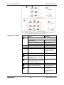
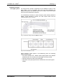
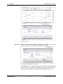
DIAG Diagnostic Software
The diagnostic software allows the display of saved and current device
states and error messages on a PC or laptop. Data transmission occurs
via the diagnostic cable (3), which is connected to the motherboard on
the TITANUS TOP · SENS® using the X2 plug (1), (see Fig. 2.8).
Fig. 2.6: Diagnostic software for reading out device states
1
2
3
4
5
X2 plug
CD-ROM dignostic software DIAG 2
Diagnostic cable
Connection to a PC
Connection to the TITANUS device
Diagnostic messages remain saved in the diagnostic software for at least
3 days in order to be able to evaluate even short, sporadically-occurring
errors (e.g. in case of changed operating conditions).
A reset of the device via the diagnostic software causes the deletion of all
saved diagnostic messages.
The software also allows the deletion of error messages.
Using diagnostic software, all saved and current diagnostic data as well
as the settings undertaken using the DIL switches can be saved as a file.
To be able to compare the data read out, save each file under a different
file name.
TIP
BOSCH
- 19 -
ST-FIR / PRM1 / A3.en
TITANUS TOP · SENS®
2 – Technical Description
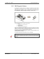
2.2.4
Device Mounting
®
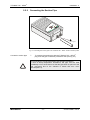
Fig. 2.8: Device mounting (1) for the TITANUS TOP · SENS smoke extraction system
The TITANUS TOP · SENS® can be mounted directly on a wall. If
necessary, for example for mounting on shelf racks, additional brackets
are available.
BOSCH
- 20 -
ST-FIR / PRM1 / A3.en
TITANUS TOP · SENS®
Technical Description - 2
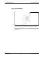
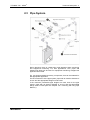
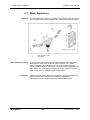
2.3 Pipe System
®
Fig. 2.9: Component selection of the TITANUS TOP · SENS pipe system
During planning, there is a distinction made between space monitoring
and equipment monitoring. For both applications, PVC pipes and
halogen-free pipes can be used. For equipment monitoring, halogen-free
pipes should be used.
Fig. 2.9 shows essential accessory components, that can be selected for
the appropriate application.
For the construction of the pipe system, pipes with an exterior diameter of
25 mm and the appropriate fittings must be used.
If the maximum permissible pipe lengths are used, then for the pipe
returns, pipes with an exterior diameter of 40 mm and the appropriate
fittings must be used (see also Chapter 4.6.3 “Planning with Long Pipe
Returns”).
BOSCH
- 21 -
ST-FIR / PRM1 / A3.en
TITANUS TOP · SENS®
2 – Technical Description
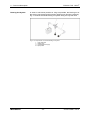
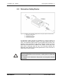
Blowing-Out System
In areas in which dust particles or icing are possible, the blowing-out of
the suction pipe system and its suction openings can become necessary.
Fig. 2.10 shows a manual blowing-out system using a 3-way ball valve.
Fig. 2.10: Components of a manual blowing-out system
1
2
A
B
BOSCH
3-way ball valve
Suction pipe
Compressed air supply
Pipe system
- 22 -
ST-FIR / PRM1 / A3.en
TITANUS TOP · SENS®
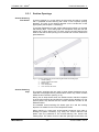
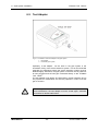
2.3.1
Suction-Reducing
Film Sheets
Technical Description - 2
Suction Openings
A suction opening is a 10 mm boring in the suction pipe that is covered
with a patented suction-reducing film sheet of the required opening
diameter. The size of the opening depends on the construction of the
pipe system (see Chapter 4, “Planning”).
To prevent displacement of the suction-reducing film sheet, it is secured
with marking tape . The marking tape is a transparent sticky film with red
edges and a 10mm large hole. It is stuck over the suction-reducing film
sheet so that the suction opening is not covered and it is also visible from
great distances.
Fig. 2.11: Suction opening with suction-reducing film sheet and marking tape
1
2
3
4
5
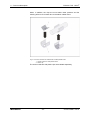
Suction-Reducing
Clips
Suction opening
Suction reducing film sheet
Marking tape
Color: transparent
Color: fire red, RAL 3000
The suction openings that are used in areas where blockages can be
expected are equipped with a patented RAS suction clip, which includes
flexible suction reduction (see Fig. 2.12).
During use in deep-freeze areas, the flexible suction reduction expands
in the suction openings and pushes the ice away during blowing-out. The
special plastic clip ensures that the suction reduction remains at the
defined location.
The standard suction-reducing film sheets type AF-x and the marking
tape are not suitable for use in low-temperature areas.
When planning in areas with environmental influences that make a
blowing-out system necessary (e.g. dust), the suction reducers with
plastic clips are preferred to the suction-reducing film sheets with
marking tape. The reason for this is that the openings can be blown out
BOSCH
- 23 -
ST-FIR / PRM1 / A3.en
TITANUS TOP · SENS®
2 – Technical Description
better. In addition, the clips are more stable under pressure and the
cleaning effect is much better due to the elastic rubber insert.
Fig. 2.12: Suction reduction for soiled areas and deep-freeze areas
1 Suction reducer for deep freeze areas
2 Plastic clip
The suction reducers with plastic clips are available separately.
BOSCH
- 24 -
ST-FIR / PRM1 / A3.en
TITANUS TOP · SENS®
2.3.2
Technical Description - 2
Air Return for Pressure Areas and
Atmospheric Loads
Fig.2.13: Principle of air return with the TITANUS TOP · SENS
1
2
3
4
5
®
Detector module
Airflow sensor
Suction unit
Air return
Pipe system
If the TITANUS TOP · SENS® and the pipe system are installed in areas
with different air pressure, the air taken in in the pressure area of the
pipe system must be returned (see Fig.2.13).
The air return can serve to equalize pressure or to prevent atmospheric
loads (e.g. odors) in neighboring spaces.
®
Fig. 2.14: TITANUS TOP · SENS with suction pipe (1) and air return (2)
The air-return pipe is connected directly through the ventilation grille to
the air-exhaust duct in the inside of the TITANUS TOP · SENS® (see
Fig. 2.14). For this, the pre-punched opening in the protective grille must
be punched out.
The air return of the smoke extraction system should not exceed 2 m.
Longer returns must be checked individually.
NOTE
BOSCH
- 25 -
ST-FIR / PRM1 / A3.en
TITANUS TOP · SENS®
2 – Technical Description
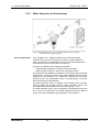
2.3.3
Water Separator for Humid Areas
Fig. 2.15: Water separator type II (1) for condensing water vapor and collecting
condensation from the pipe system (2)
Areas of Application
If the TITANUS TOP · SENS® is operated in environments where
condensation can form in the extraction system, a water separator is
used. The formation of condensation can occur with sharp temperature
fluctuations and in areas with fresh-air monitoring.
There are two different water separators available:
-
Standard water separator for spaces with high humidity
- Water separator type II for spaces with very high humidity
The standard water separator is installed in an ascending part of the pipe
system with a connection to the suction pipe towards the bottom and a
connection to the TITANUS TOP · SENS® via a PG29 screw connection
towards the top. The condensation occurs on the false floors, over which
the humid air flows in two directions.
The water separator type II is installed at the lowest point of the pipe
system between the air filter and the smoke extraction system. The
45° angles allow optimal distance from the wall (see Fig. 2.15).
The water separator type II can be operated in a temperature range from
0°C to +50°C. The sinter filter in the water separator has a pore width of
50 µm and causes additional rough absorption of soil particles.
BOSCH
- 26 -
ST-FIR / PRM1 / A3.en
TITANUS TOP · SENS®
2.3.4
Technical Description - 2
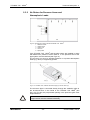
Detonation Safety Barrier
for Areas in Danger of Explosion
Fig. 2.16: Detonation safety barrier (1) in extraction pipe system and, if necessary, in the air
return
1
2
3
4
Detonation safety barrier
Pipe system
Metal pipe
Explosive area
In case of ignition of steam/air mixtures or gas/air mixtures in the
TITANUS TOP · SENS®, pipe explosions or detonations can occur. This
depends on the composition, concentration, temperature, and pressure
of the flammable mixture.
The detonation safety barrier is a flame trap, that is flame-proof in the
face of pipe explosions (deflagrations) and detonations (see Fig. 2.16).
In normal operation, the steam and gas mixtures flow in any direction
through the safety barrier. In case of an ignition of the mixture in the
upstream smoke extraction system, the existing detonation is arrested.
The ignition is prevented by the flame filter . If combustion of the mixture
occurs in the flame filters, a rebound of the detonation front may occur.
To prevent this, a minimum pipe length of 1.0 m between the installation
point of the detonation safety barrier and a possible ignition source
(smoke suction system) must be maintained. Permanent fire prevention
is thus achieved indirectly.
NOTE
The connecting pipe between the smoke extraction system and the
detonation safety barrier must be made of metal. During installation, be
sure that the threaded connections are bolted together gas-tight using
synthesol or a sealing band.
Type
BOSCH
PROTEGO DA-G DN - IIC
Explosion groups
I + II
Connections
PG 29 screw connections
Operating pressure (max.)
1.1 bar
Approval
German Federal Institute for Material Testing
- 27 -
ST-FIR / PRM1 / A3.en
TITANUS TOP · SENS®
2 – Technical Description
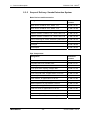
2.3.5
Scope of Delivery: Smoke Extraction System
Basic Devices and Accessories
Designation
Reference
number
Basic device TITANUS TOP · SENS® TT-1
4.998.143.397
®
Basic device TITANUS TOP · SENS TT-2
4.998.143.398
®
Detector module TITANUS TOP · SENS DM-TT-80
4.998.143.400
Detector module TITANUS TOP · SENS® DM-TT-25
4.998.143.401
Detector module TITANUS TOP · SENS® DM-TT-05
4.998.143.402
Device mounting for smoke extraction systems MT-1
4.998.143.410
DIAG diagnostic software
4.998.143.412
Test pipe
4.998.148.848
Test adapter
4.998.148.849
Pipe Components
BOSCH
Designation
Reference
number
PVC transparent hose, exterior ∅ 25 mm
2.799.330.762
Polywell hose PG16, flexible, black
4.998.121.071
PVC ring nut, M20
4.998.121.072
PVC quick-close coupling, straight, M20
4.998.121.076
PVC quick-close coupling, angled, M20
4.998.121.077
PVC 3-way ball valve, for pipe exterior ∅ 25 mm
4.998.121.068
PVC flange for ventilator duct
4.998.121.069
Dust collector, for pipe exterior ∅ 25 mm
4.998.121.063
Detonation safety barrier, for pipe exterior ∅ 25 mm
4.998.121.062
Water separator, for pipe exterior ∅ 25 mm
4.998.121.060
Water separator type II PVC, exterior ∅ 25 mm
4.998.121.061
Filter box small, for pipe exterior ∅ 25 mm
4.998.121.064
Replacement filter mat for filter box small
4.998.121.066
Filter box large, for pipe exterior ∅ 25 mm
4.998.121.065
Replacement filter mat for filter box large
4.998.121.067
- 28 -
ST-FIR / PRM1 / A3.en
TITANUS TOP · SENS®
Technical Description - 2
Components for Suction Openings
Designation
Reference
number
Marking tape suction-reduction film sheet AF-BR,
10pcs
4.998.143.413
Suction-reduction film sheet 2.0 mm AF-2.0, 10pcs
4.998.143.416
Suction-reduction film sheet 2.5 mm AF-2.5, 10pcs
4.998.143.417
Suction-reduction film sheet 3.0 mm AF-3.0, 10pcs
4.998.143.418
Suction-reduction film sheet 3.2 mm AF-3.2, 10pcs
4.998.143.419
Suction-reduction film sheet 3.4 mm AF-3.4, 10pcs
4.998.143.420
Suction-reduction film sheet 3.6 mm AF-3.6, 10pcs
4.998.143.422
Suction-reduction film sheet 3.8 mm AF-3.8, 10pcs
4.998.143.423
Suction-reduction film sheet 4.0 mm AF-4.0, 10pcs
4.998.143.424
Suction-reduction film sheet 4.2 mm AF-4.2, 10pcs
4.998.143.425
Suction-reduction film sheet 4.4 mm AF-4.4, 10pcs
4.998.143.426
Suction-reduction film sheet 4.6 mm AF-4.6, 10pcs
4.998.143.427
Suction-reduction film sheet 5.0 mm AF-5.0, 10pcs
4.998.143.428
Suction-reduction film sheet 5.2 mm AF-5.2, 10pcs
4.998.143.429
Suction-reduction film sheet 5.6 mm AF-5.6, 10pcs
4.998.143.430
Suction-reduction film sheet 6.0 mm AF-6.0, 10pcs
4.998.143.431
Suction-reduction film sheet 6.8 mm AF-6.8, 10pcs
4.998.143.432
Suction-reduction film sheet 7.0 mm AF-7.0, 10pcs
4.998.143.433
Plastic clips with marking tape for deep-freeze facilities and blowing-out
systems are sold separately.
NOTE
BOSCH
- 29 -
ST-FIR / PRM1 / A3.en
TITANUS TOP · SENS®
3 – Technical Data
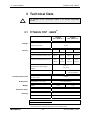
3 Technical Data
All specified current consumption relates to an ambient temperature
of 20°C.
NOTE
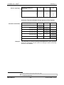
3.1 TITANUS TOP · SENS®
TITANUS
TOP · SENS® TT-2
TITANUS
TOP · SENS® TT-1
Supply voltage (Ue)
Voltage
14 to 30 V DC
Rated supply voltage
24V DC
UL1= 6,9 V
Current
Starting current (at 24 V)
Current consumption stand-by (at 24
V)
Current consumption alarm (at 24 V)
UL = 9 V
300 mA
230 mA2
UL = 9 V
350 mA
300 mA
275 mA
340 mA
max.
max.
max.
max.
300 mA
360 mA
350 mA
430 mA
Contact load capacity of the alarm
30 V, 1 A
and malfunction relay breaking
max. 24 W
capacity
Integrated coupler
UL = 6.9 V
1 fire control interface
1 fire control interface
and 1 fire interface
Lwa in compliance with
Acoustic power level
45 dB(A)
EN 27779, 1991
Dimensions (H x W x D mm)
Dimensions
Weight
Weight
1.6 kg
Protection class (DIN IEC 34 part 5)
Protection class
Material
Housing
2
BOSCH
1.7 kg
IP 20
Plastic (ABS)
Color
1
113 x 200 x 292 mm
papyrus white, RAL 9018
UL = blower voltage
The current values can deviate depending on the pipe system used.
- 30 -
ST-FIR / PRM1 / A3.en
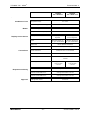
TITANUS TOP · SENS®
Technical Data - 3
TITANUS
TOP · SENS®TT-1
TITANUS
TOP · SENS® TT-2
‘
Conditions of use
Blower
Temperature range
0° to +50°C
Rel. humidity (non-condensing)
10 to 95 %
Construction type
radial
Lifespan of the blower (12 V)
Displays on the device
Display of the smoke level
Alarm
Malfunction
Level display with 10
2 level displays with
segments
ever 10 segments
Red alarm display for
2 red alarm displays for
info-, pre- and fire alarm
info-, pre- and fire alarm
Yellow collective malfunction
Operation
Connections
43,500 hour at 24°C
Green operation display
Device connection
Clamps for max. 1.5 mm² strands
Cable
Twisted in pairs, shielded or unshielded
Cable entry points
1 x M 20
2 x M 25
Conical pipe connections
Response sensitivity
Approval
BOSCH
1 x for pipe ∅ 25 mm
2 x for pipe ∅ 25 mm
1 x for air return
1 x for air return
∅ 25 mm
∅ 25 mm
Detector module DM-TP-80 …
max. light obscuration 0.8 %/m
Detector module DM-TP-25 …
max. light obscuration 0.25 %/m
Detector module DM-TP-05 ...
max. light obscuration 0.05 %/m
VdS approval number
- 31 -
G 20 40 83
ST-FIR / PRM1 / A3.en
TITANUS TOP · SENS®
3 – Technical Data
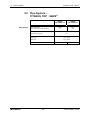
3.2 Pipe System –
TITANUS TOP · SENS®
Pipe System
max. pipe length
max. number of suction openings
TITANUS
TOP · SENS® TT-1
TITANUS
TOP · SENS®TT-2
180 m
360 m
24
48
max. length suction hose
per ceiling entry point
1m
Temperature range
PVC pipe
-10°C..+60°C
ABS pipe
-40°C..+80°C
max. monitoring space
BOSCH
- 32 -
2880 m
2
5,760 m²
ST-FIR / PRM1 / A3.en
TITANUS TOP · SENS®
Planning - 4
4 Planning
Chapters 4.2 and 4.3 will describe the planning for the pipe system and
the airflow monitoring. Chapter 4.4 treats the specification of the
sensitivity and Chapter 4.5 the planning limits. With standard
requirements for airflow monitoring, the standard planning described in
Chapters 4.6.2 – 4.6.4 should be selected. If more sensitive airflow
monitoring is needed, then the planning with single-hole monitoring
described in Chapter 4.6.5 applies. Chapter 4.7 describes the guidelines
for planning with forced airflow.
4.1 Regulations
The following planning instructions are oriented towards the system limits
of the TITANUS TOP · SENS®. Here, the corresponding national
regulations of the countries in their respectively-applicable version must
be adhered to and planning must be adjusted to these.
In Germany, the following regulations must be adhered to:
• DIN VDE 0833 parts 1 and 2 "Sec. sys for fire, intrusion, and hold-up"
• additional provisions for the installation of fire detection systems,
which are published by fire directors of fire departments, by the
construction supervision authorities or by the construction law
authorities that have only local validity.
For VdS systems, the following guidelines must also be adhered to:
• "Guideline for automatic fire detection systems, planning and
installation", VdS Schadenverhütung GmbH, Cologne (VdS 2095)
• the guideline "Installation protection for electrical and electronic
systems" VdS Schadenverhütung GmbH, Cologne (VdS 2304)
For CEA requirements, the following guidelines must also be
adhered to:
•
The CEA guideline demands the recognition of an airflow
malfunction if a 50% change of the main airflow occurs. In addition,
the size of the suction openings is specified at a minimum ø 2,0 mm
During planning, the following guidelines must also be adhered to:
•
The planning limits described in Chapter 4.5 apply.
•
The maximum monitoring space of a suction opening is 120 m².
NOTE
BOSCH
- 33 -
ST-FIR / PRM1 / A3.en
TITANUS TOP · SENS®
4 – Planning
4.2 Pipe System
The suction mains must be designed such that all possible fires in the
monitoring area can be dealt with in the early stage.
The number of suction openings and the construction of the pipe system
depends on the size and geometry of the monitoring area. The pipe
system must be laid out according to the planning guidelines in this
chapter, taking into account the following issues:
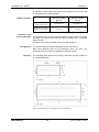
Symmetrical construction Preferably, the pipe system should be laid out symmetrically, that is:
• same number of suction openings per pipe branch
• same pipe branch lengths (should not exceed ± 10% deviation)
• same distance between neighboring suction openings on the smoke
extraction pipe (should not exceed ± 10% deviation)
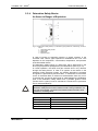
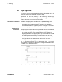
Asymmetrical
construction
If the pipe system must be laid out asymmetrically due to circumstances
of construction (see Fig. 4.1), the following conditions apply:
• the number and length of the suction openings of the shortest and
longest pipe branch of the pipe system may not exceed a ratio of 1:2.
• the distance between neighboring suction openings on the smoke
extraction pipe must be equal (should not exceed ± 20% deviation)
• the diameter of the suction openings are determined separately for
each pipe branch. they depend on the total number of suction
openings on the respective pipe branch.
Fig. 4.1 shows an example of a U pipe system with 3 or 6 suction
openings and the diameters of the suction openings calculated according
to Chapter 4.6.2 “Standard Planning.“
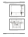
Fig. 4.1: Example of a symmetrical (above) and an asymmetrical (below) U pipe system
BOSCH
- 34 -
ST-FIR / PRM1 / A3.en
TITANUS TOP · SENS®
Planning - 4
Longer pipe feed lines
In many application cases, larger distances between the smoke
extraction system and the suction pipe must be bridged. For this, pipe
feed lines with larger diameters are used in order to guarantee a
maximum planning (see also Chapter 4.6.3 “Planning with Long Pipe
Feed Lines").
Branch lengths
To achieve short transport times for the smoke aerosoles in the suction
pipe and thus quick detection, it is better to plan several short branches
than fewer long ones (preferably U and double-U pipe system).
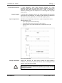
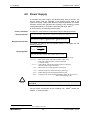
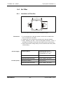
Pipe configurations
Depending on the geometry of the room, 3 pipe configurations can be
selected (see Fig. 4.2):
•
I-pipe: Pipe system without branchings.
•
U-pipe: Pipe system that branches into 2 pipe branches.
•
Double-U-pipe: Pipe system that branches symmetrically into 4 pipe
branches.
Fig. 4.2: Pipe configurations
Change of direction
NOTE
BOSCH
Angles and bends in the pipe system increase the flow resistance.
Therefore, they should only be used where, due to building-technical
reasons, they cannot be avoided.
It is preferable to use bends rather than angles.
The detection time will be influenced significantly by too high a number
of changes of direction.
- 35 -
ST-FIR / PRM1 / A3.en
TITANUS TOP · SENS®
4 – Planning
Special cases
If the pipe system does not correspond to the planning guidelines
described here due to building-technical circumstances, it must be
calculated separately for the case in question on request.
Testing
For critical applications, test the secure detection with activation
attempts. Check also whether there is airflow to the individual suction
openings.
To increase the transport speed in critical areas of the pipe system, the
blower voltage can be increased from 6.9 V to 9 V.
TIP
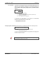
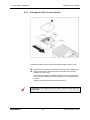
Two-detector dependency One suction line must be assigned per
detector module. Both detector modules of a device must be evaluated
independently of one another. Per smoke extraction system only one
extinguishing area may be monitored.
Fig. 4.3: Pipe configurations for two-detector dependency
4.3 Airflow Monitoring
The planning of airflow monitoring of the smoke extraction pipes is
selected taking into account the respective national regulations for the
country in question.
CEA requirement
The CEA 4022 "Requirements and test methods for aspirating smoke
detectors" requires that a smoke extraction system notifies of an airflow
malfunction if there is a 50% change in the main airflow.
If with a blockage of 50% of all existing suction openings an airflow
malfunction is detected, thus the recognition of a 50% change in the main
airflow is guaranteed.
Regardless of this CEA requirement, areas can be monitored with the
TITANUS TOP · SENS® that
• due to the organization of the monitoring areas require single-hole
monitoring,
• require a break recognition that causes the drop-off of 50% of the
suction openings present in the pipe system.
Gradation of the suction
openings
BOSCH
For even detection, it is necessary that all suction openings have nearly the
same air flow rate. For this reason, with large distances between the suction
- 36 -
ST-FIR / PRM1 / A3.en
TITANUS TOP · SENS®
Planning - 4
openings (> 4 m), the boring diameter to the pipe end must be larger. For
the respective diameters, see the tables in Chapters 4.6.2 – 4.6.5.
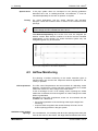
Adjustment of the
airflow sensitivity
The sensitivity of the airflow sensor must be adjusted to the application
case. For example, a long pipe system requires a sensitive setting of the
airflow sensor. The activation threshold and thus the sensitivity of the
airflow sensor can be set on 4 levels.
Level
I
II
III
IV
Activation threshold
small
medium
large
very large
Sensitivity
very high
high
medium
low
Selection of the largest possible, precisely still-approved level is
recommended.
TIP
Restrictions
The airflow monitoring may only be set to level 1 if the pipe system has
been planned in accordance with Chapter 4.6.5 Single-Hole Monitoring.
Level II may only be set if the pipe system is structured symmetrically
and the airflow sensor is equalized depending on the air pressure (see
Chapter 7.1.2 "Air Pressure-Dependent Calibration”).
With asymmetrically-structured pipe systems, only the levels III to IV
of the airflow monitoring may be set.
NOTE
Level IV of the activation threshold can also be set to exclude particularly
large air-pressure fluctuations. With this threshold, the airflow monitoring
is so insensitive that a blockage is only recognizable if it causes at least a
50% change in the main airflow.
Air pressure differences
NOTE
BOSCH
There must be equivalent air pressure along the suction pipe.
If the smoke extraction system and pipe system are in areas with
different air pressure, then a return of the air sucked in by the TITANUS
TOP · SENS® must be provided in the pressure area of the pipe system
(see Chapter 2.3.5 “Air Return“).
- 37 -
ST-FIR / PRM1 / A3.en
TITANUS TOP · SENS®
4 – Planning
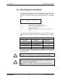
4.4 Specifying the Sensitivity
The response sensitivity at the individual detection points (smoke
extraction openings) depends on the detector module used, the
sensitivity level set, and the number of detection points. It is calculated
from:
S DP = S TOPSENS × N
proj . DP
SDP
=
Sensitivity of the individual detection point
(smoke extraction opening, pure calculation value)
STOPSENS
=
selected detector module sensitivity of
®
TITANUS TOP · SENS
Nproj. DP
=
number of all planned detection points in the system per detector
module
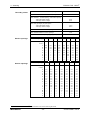
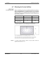
The table shows the selectable sensitivity levels of the three detector
modules of the TITANUS TOP · SENS®. The default settings are shaded
gray.
Response Sensitivity (Alarm) TITANUS TOP · SENS®
Detector module
DM-TT-05
Detector module
DM-TT-25
Detector module
DM-TT-80
0.4 % light obscuration/m
2 % light obscuration/m
not occupied
0.2 % light obscuration/m
1 % light obscuration/m
not occupied
0.1 % light obscuration/m
0.5 % light obscuration/m
0.5 % light obscuration/m
0.25% light obscuration/m
1.6 % light obscuration/m
0.8 % light obscuration/m
The planning always occurs according to the instructions for point-type
smoke detectors.
Here it must be ensured that the sensitivity of the individual detection
point SDP achieves at least a value of ≤ 3.5 %/m light obscuration.
NOTE
NOTE
BOSCH
When monitoring several areas with a smoke extraction system, the
total sensitivity of the suction openings within a closed area must
amount to ≤ 3.5%/m light diffusion.
If this value is not reached, it is recommended that a higher sensitivity
be set.
- 38 -
ST-FIR / PRM1 / A3.en
TITANUS TOP · SENS®
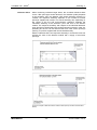
Collective effect
Planning - 4
When monitoring individual larger areas, the so-called collective effect
occurs. With point-type smoke detectors, the detection quality depends
on the sensitivity set in the detector. With smoke extraction systems, by
contrast, the response sensitivity depends on the number of suction
openings supplied with smoke. The actual sensitivity lies, depending on
the course of the fire and environmental conditions, between the
calculated sensitivity at the detection point and that in the detector
module. The response sensitivity with respect to the individual detection
point will improve significantly with smoke extraction systems in case of a
spreading fire since it can be assumed that ever more suction openings
(see Fig. 4.6) will be supplied with smoke simultaneously.
With the collective effect, the response sensitivity in an extreme case can
achieve the value of the detector module with a supply of all suction
openings.
F
i
g
.
4
.
5
/
4
.
6
:
E
x
a
m
p
l
e
o
f
d
e
t
e
c
F
i
g
.
F
ig 4.5/4.6: Example of detection without collective effect (above) and with collective effect
(below)
BOSCH
- 39 -
ST-FIR / PRM1 / A3.en
TITANUS TOP · SENS®
4 – Planning
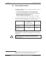
4.5
Planning Boundaries
The following boundary values must always be adhered to with the
TITANUS TOP · SENS®:
• the minimum pipe length between 2 suction openings is 0.1 m.
• the maximum pipe length between 2 suction openings is 12 m.
• the maximum monitoring space per suction opening is 120 m² for the
detector modules DM-TP-05 and DM-TP-25 and
60 m² for the detector module DM-TP-80.
• a maximum of 24 suction openings per pipe system1 are possible2.
The maximum total monitoring space of the TITANUS TOP · SENS® and
the maximum total pipe length depends on the planning selected.
Airflow Monitoring
Airflow monitoring according
Maximum total monitoring
3
space per
TITANUS TOP · SENS®
Max. pipe length
2,880 m²
180 m
1,680 m²
140 m
3
to VdS guideline
Airflow monitoring according
to planned single-hole
monitoring
With the TITANUS TOP · SENS® TT-2, 2 pipe systems with the maximum
values specified in the table may be operated. These values apply per
pipe system.
After selecting the airflow monitoring and the associated planning
boundaries, these must be checked against limitations by countryspecific regulations!
NOTE
1
®
With the TITANUS TOP · SENS TT-2 having two pipe systems, max. 48 suction openings.
Plans/project forms that are not described in the manual should be requested.
3
Depending on the planning selected, some restricted values may apply.
2
BOSCH
- 40 -
ST-FIR / PRM1 / A3.en
TITANUS TOP · SENS®
Planning - 4
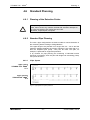
4.6
Standard Planning
4.6.1
Planning of the Detection Points
NOTE
4.6.2
If the planning on location deviates from the standard plans described
below, then it must in any case be checked with activation attempts for
the correct recognition of a malfunction and a fire.
Otherwise, a special plan is required.
Standard Pipe Planning
The next 3 pipe configurations are basic models for secure detection in
the monitoring area according to VdS guidelines.
If the pipe length to be planned is no longer than 40 – 100 m and the
maximum distance between the suction openings is not more than 4 m,
then the simplified plan (Chap. 4.6.4) can be used. This plan, for
example, is preferred for equipment protection.
If, by contrast, for pipe planning the monitoring of individual suction
openings is necessary, then the plan with single-hole monitoring (Chap.
4.6.5) must be used.
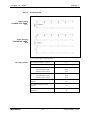
4.6.2.1
I-Pipe System
1 pipe system
TITANUS TOP · SENS®
TT-1
2 pipe systems
TITANUS TOP · SENS®
TT-2
Fig. 4.7: I-pipe system for space protection
BOSCH
- 41 -
ST-FIR / PRM1 / A3.en
TITANUS TOP · SENS®
4 – Planning
Boundary values
Min. distance TITANUS® – 1st suction opening
4m
Max. distance TITANUS® – 1st suction opening
20 m
st
Max. distance 1 suction opening -- last suction opening
- with small blower voltage
60 m
- with larger blower voltage
80 m
Max. total pipe length per pipe system
- with small blower voltage
80 m
- with larger blower voltage
100 m
Min. distance between 2 suction openings
4m
Max. distance between 2 suction openings
12 m
Max. number of suction openings (n) per pipe system
Number of openings
Suction openings
16
2
3
4
5
6
7
8
9
A
6.0
5.0
4.2
3.8
3.2
3.0
2.5
2.5
B
6.8
5.2
4.4
3.8
3.2
3.0
2.5
2.5
C
—
5.2
4.6
4.0
3.6
3.0
3.0
2.5
D
—
—
4.6
4.0
3.6
3.4
3.0
3.0
E
—
—
—
4.4
4.0
3.4
3.4
3.0
F
—
—
—
—
4.0
3.8
3.4
3.4
G
—
—
—
—
—
3.8
3.8
3.4
H
—
—
—
—
—
—
3.8
3.8
I
—
—
—
—
—
—
—
3.8
Number of openings
10
11
12
13
14
15
16
A
2.0
2.0
2.0
2.0
2.0
2.0
2.0
B
2.0
2.0
2.0
2.0
2.0
2.0
2.0
C
2.5
2.0
2.0
2.0
2.0
2.0
2.0
D
2.5
2.5
2.5
2.0
2.0
2.0
2.0
E
3.0
2.5
2.5
2.5
2.5
2.5
2.5
F
3.0
3.0
2.5
2.5
2.5
2.5
2.5
G
3.4
3.0
3.0
2.5
2.5
2.5
2.5
H
3.4
3.4
3.0
3.0
2.5
2.5
2.5
I
3.6
3.4
3.0
3.0
3.0
3.0
3.0
J
3.6
3.6
3.4
3.0
3.0
3.0
3.0
K
—
3.6
3.4
3.4
3.0
3.0
3.0
L
—
—
3.4
3.4
3.4
3.0
3.0
M
—
—
—
3.4
3.4
3.4
3.4
N
—
—
—
—
3.4
3.4
3.4
O
—
—
—
—
—
3.4
3.4
P
—
—
—
—
—
—
3.4
∅ Suction opening
4
in mm )
Suction openings
∅ Suction opening
4
in mm )
4
BOSCH
Punch diameter of the suction-reducing film sheet
- 42 -
ST-FIR / PRM1 / A3.en
TITANUS TOP · SENS®
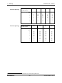
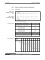
4.6.2.2
Planning - 4
U-Pipe System
1 pipe system
TITANUS TOP · SENS®
TT-1
2 pipe systems
TITANUS TOP · SENS®
TT-2
Fig. 4.8: U-pipe system for space protection
Boundary values
Min. distance TITANUS® – T piece
®
Max. distance TITANUS – T piece
4m
20 m
Max. branch length
- with small blower voltage
60 m
- with larger blower voltage
70 m
Max. total pipe length per pipe system
- with small blower voltage
140 m
- with larger blower voltage
160 m
Min. distance between 2 suction
openings
4m
Min. distance between 2 suction
openings
12 m
Max. number of suction openings (n) per
pipe system
BOSCH
18
- 43 -
ST-FIR / PRM1 / A3.en
TITANUS TOP · SENS®
4 – Planning
Number of openings
per pipe system
Suction openings
2
4
6
8
10
A
5.2
3.6
3.4
3.2
2.5
B
—
4.0
3.4
3.2
3.0
C
—
—
3.6
3.4
3.0
D
—
—
—
3.4
3.2
E
—
—
—
—
3.2
F
—
—
—
—
—
G
—
—
—
—
—
∅ Ansaugöffnung in
5
mm )
Number of openings
per pipe system
Suction openings
12
14
16
18
A
2.5
2.0
2.0
2.0
B
2.5
2.0
2.0
2.0
C
2.5
2.5
2.0
2.0
D
3.0
2.5
2.5
2.0
E
3.0
3.0
2.5
2.5
F
3.2
3.0
3.0
2.5
G
—
3.2
3.0
2.5
H
—
—
3.0
3.0
I
—
—
—
3.0
∅ Suction opening in
5
mm )
5
BOSCH
Punch diameter of the suction-reducing film sheet
- 44 -
ST-FIR / PRM1 / A3.en
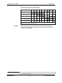
TITANUS TOP · SENS®
Planning - 4
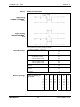
4.6.2.3
Double-U-Pipe System
1 pipe system
TITANUS TOP · SENS®
TT-1
2 pipe systems
TITANUS TOP · SENS®
TT-2
Fig. 4.9: Double-U-pipe system for space protection
Min. distance TITANUS® – last T piece
Boundary values
4m
Max. distance TITANUS® – last T piece
20 m
Max. branch length with
- smaller blower voltage
- with larger blower voltage
Max. total pipe length per pipe system
- with small blower voltage
- with larger blower voltage
Min. distance between 2 suction
openings
Min. distance between 2 suction
openings
Max. number of suction openings (n) per
pipe system
Number of openings per
pipe system
Suction openings
30 m
40 m
140 m
180 m
4m
12 m
24
4
8
12
16
20
24
A
4.0
3.0
2.5
2.0
2.0
2.0
B
—
3.4
3.0
2.5
2.0
2.0
C
—
—
3.0
3.0
2.5
2.0
D
—
—
—
3.0
2.5
2.5
E
—
—
—
—
3.0
2.5
F
—
—
—
—
—
3.0
6
∅ Suction opening in mm )
6
BOSCH
Punch diameter of the suction-reducing film sheet
- 45 -
ST-FIR / PRM1 / A3.en
TITANUS TOP · SENS®
4 – Planning
4.6.3
Planning with Long Pipe Feed Lines
For planning, pipes with a diameter of 40 mm are used. This applies for
the previously-depicted pipe configurations.
Fig. 4.10: Example of a pipe system with long pipe feed lines for space monitoring
For a pipe system for space monitoring, the following boundaries apply:
Pipe diameter
25mm
40mm
*
Max. length A
6.9V*
9V*
20m
60m
Max. length B
6.9V*
9V*
60 m
80 m
selected blower voltage, depends on the pipe system
Fig. 4.11: Example of special planning for high-rack storage
For planning high-rack storage (Fig. 4.11), a basic pipe can be installed
from which stitch-shaped suction pipes branch off.
The specifications for this pipe system are:
BOSCH
•
max. pipe length 180 m (4 x 20 m branches + 100 m basic pipe)
•
max. basic pipe length 100 m, basic pipe diameter 40 mm
- 46 -
ST-FIR / PRM1 / A3.en
TITANUS TOP · SENS®
Planning - 4
4.6.4
Simplified Pipe Planning
The simplified planning is used for equipment protection and in spaces
with small dimensions. The advantage of this planning is the uniform
diameter of the suction openings.
4.6.4.1
I-Pipe System
d
1 pipe system
TITANUS TOP · SENS®
TT-1
TITANUS®
i
10
9
8
7
6
5
4
3
2
1
2 pipe systems
TITANUS TOP · SENS®
TT-2
d
TITANUS®
10
9
8
7
6
5
4
3
2
1
2
1
i
10
9
8
7
6
5
4
3
2
1
Fig. 4.12: I-pipe system, e.g. for equipment protection
Boundary values
Min. distance TITANUS® – 1st suction opening
2m
®
Max. distance TITANUS – 1st suction opening
20 m
st
Max. distance 1 suction opening -- last suction opening
20 m
Max. total pipe length Ø 25 mm
40 m
Max. number of suction openings (n) per pipe system
18
Minimum distance between the suction openings (d)
0.1 m
Maximum distance between the suction openings (d)
4m
Suction openings
Number of
openings
∅ All suction
openings in mm7)
Suction openings
7
BOSCH
2
3
4
5
6
7
8
9
10
6.0
5.0
4.4
4.0
3.6
3.4
3.2
3.0
3.0
Number of
openings
11
12
13
14
15
16
17
18
∅ All suction
openings in mm7)
3.0
3.0
2.5
2.5
2.5
2.5
2.5
2.5
Punch diameter of the suction-reducing film sheet
- 47 -
ST-FIR / PRM1 / A3.en
TITANUS TOP · SENS®
4 – Planning
4.6.4.2
U-Pipe System
1 pipe system
TITANUS TOP · SENS®
TT-1
d
TITANUS®
10
9
8
7
6
5
i
4
3
2
1
2 pipe systems
TITANUS TOP · SENS®
TT-2
2
1
10
9
10
9
8
7
8
7
6
5
TITANUS®
6
5
4
3
2
1
4
3
i
2
1
Fig. 4.13: U-pipe system, e.g. for equipment protection
Boundary values
Min. distance TITANUS® – T piece
2m
Max. distance TITANUS® – T piece
20 m
Max. branch length
20 m
Max. total pipe length Ø 25 mm
60 m
Max. number of suction openings (n) per pipe system
18
Minimum distance between the suction openings (d)
0.1 m
Maximum distance between the suction openings (d)
4m
Number of openings
Suction openings
∅ All suction
openings in mm8)
8
BOSCH
2
4
6
8
10
12
14
16
18
6.0
4.4
3.6
3.2
3.0
3.0
2.5
2.5
2.5
Punch diameter of the suction-reducing film sheet
- 48 -
ST-FIR / PRM1 / A3.en
TITANUS TOP · SENS®
Planning - 4
4.6.4.3
Double-U-Pipe System
d
1 pipe system
TITANUS TOP · SENS®
TT-1
TITANUS®
i
0
1
9
8
7
6
5
4
3
2
1
2 pipe systems
TITANUS TOP · SENS®
TT-2
TITANUS®
®
TI TAN US P RO · SENS 2
10
9
8
7
6
5
4
3
2
1
2
i
1
10
9
8
7
6
5
4
3
2
1
2
1
Fig. 4.14: Double--U-pipe system, e.g. for equipment protection
Min. distance TITANUS® – last T piece
Boundary values
2m
®
Max. distance TITANUS – last T piece
20 m
Max. branch length
20 m
Max. total pipe length Ø 25 mm
100 m
Max. number of suction openings (n) per pipe system
20
Minimum distance between the suction openings (d)
0.1 m
Maximum distance between the suction openings (d)
4m
Number of openings per pipe
system
Suction openings
∅ All suction openings in mm
9
BOSCH
9)
4
8
12
16
20
4.0
3.4
3.0
2.5
2.0
Punch diameter of the suction-reducing film sheet
- 49 -
ST-FIR / PRM1 / A3.en
TITANUS TOP · SENS®
4 – Planning
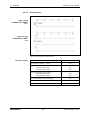
4.6.5
Pipe Planning for Single-Hole Monitoring
4.6.5.1
I-Pipe System
1 pipe system
TITANUS TOP · SENS®
TT-1
2 pipe systems
TITANUS TOP · SENS®
TT-2
Fig. 4.15: I-pipe system for space protection
Boundary values
Min. distance TITANUS® – 1st suction opening
4m
Max. distance TITANUS® – 1st suction opening
20 m
st
Max. distance 1 suction opening -- last suction opening
- with small blower voltage
40 m
- with larger blower voltage
60 m
Max. total pipe length per pipe system
- with small blower voltage
60 m
- with larger blower voltage
80 m
Min. distance between 2 suction openings
4m
Max. distance between 2 suction openings
12 m
Max. number of suction openings (n) per pipe system
Number of
openings
Suction openings
10
2
3
4
5
6
7
8
9
10
A
6.0
5.0
4.2
3.8
3.2
3.0
2.5
2.5
2.0
B
6.8
5.2
4.4
3.8
3.2
3.0
2.5
2.5
2.0
C
—
5.2
4.6
4.0
3.6
3.0
3.0
2.5
2.5
D
—
—
4.6
4.0
3.6
3.4
3.0
3.0
2.5
E
—
—
—
4.4
4.0
3.4
3.4
3.0
3.0
F
—
—
—
—
4.0
3.8
3.4
3.4
3.0
G
—
—
—
—
—
3.8
3.8
3.4
3.4
H
—
—
—
—
—
—
3.8
3.8
3.4
I
—
—
—
—
—
—
—
3.8
3.6
J
—
—
—
—
—
—
—
—
3.6
∅ Suction opening
10
in mm )
10
BOSCH
Punch diameter of the suction-reducing film sheet
- 50 -
ST-FIR / PRM1 / A3.en
TITANUS TOP · SENS®
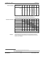
Planning - 4
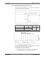
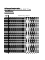
Activation Thresholds I-Pipe System
Number of openings
Activation threshold
2
3
4
5
6
7
8
9
10
11
1 blocked opening
2 blocked openings
III
{
12
—
—
III
II
I
I
—
—
{
III
III
II
I
I
—
—
3 blocked openings
{
{
{
{
III
III
II
I
I
4 blocked openings
{
{
{
{
{
{
III
II
I
5 blocked openings
{
{
{
{
{
{
{
{
II
… will be recognized by the setting level x
Example
If the blockage of 3 suction openings of a total of 7 suction openings
should be recognized, then the switch for setting the airflow monitoring
should be set to level III.
11
12
BOSCH
— not possible
{ does not make sense
- 51 -
ST-FIR / PRM1 / A3.en
TITANUS TOP · SENS®
4 – Planning
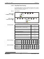
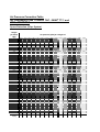
4.6.5.2
U-Pipe System
1 pipe system
TITANUS TOP · SENS®
TT-1
2 pipe systems
TITANUS TOP · SENS®
TT-2
Fig. 4.16: U-pipe system for space protection
Boundary values
Min. distance TITANUS® – T piece
®
Max. distance TITANUS – T piece
4m
20 m
Max. branch length
- with small blower voltage
40 m
- with larger blower voltage
50 m
Max. total pipe length per pipe system
- with small blower voltage
100 m
- with larger blower voltage
120 m
Min. distance between 2 suction openings
4m
Max. distance between 2 suction openings
12 m
Max. number of suction openings (n) per pipe system
BOSCH
- 52 -
14
ST-FIR / PRM1 / A3.en
TITANUS TOP · SENS®
Planning - 4
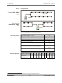
Number of openings
per pipe system
Suction openings
2
4
6
8
10
12
14
A
5,2
3,6
3,4
3,2
2,5
2,5
2,0
B
—
4,0
3,4
3,2
3,0
2,5
2,0
C
—
—
3,6
3,4
3,0
2,5
2,5
D
—
—
—
3,4
3,2
3,0
2,5
E
—
—
—
—
3,2
3,0
3,0
F
—
—
—
—
—
3,2
3,0
G
—
—
—
—
—
—
3,2
10
12
14
∅ Suction opening
13
in mm )
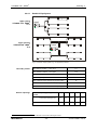
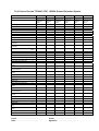
Activation Thresholds U-Pipe System per Pipe System
Number of openings
Activation thresholds
1 blocked opening
2 blocked openings
2
4
6
8
III
II
I
—
—
—
—
III
II
I
—
—
—
{
15
14
3 blocked openings
{
{
III
II
I
—
—
4 blocked openings
{
{
{
III
II
I
—
5 blocked openings
{
{
{
{
III
II
I
6 blocked openings
{
{
{
{
{
III
II
7 blocked openings
{
{
{
{
{
{
III
… will be recognized by the setting level x
Example
If the blockage of 3 suction openings of a total of 8 suction openings
should be recognized, then the switch for setting the airflow monitoring
should be set to level II.
13
14
15
BOSCH
Punch diameter of the suction-reducing film sheet
— not possible
{ does not make sense
- 53 -
ST-FIR / PRM1 / A3.en
TITANUS TOP · SENS®
4 – Planning
4.6.5.3
Double-U-Pipe System
1 pipe system
TITANUS TOP · SENS®
TT-1
2 pipe systems
TITANUS TOP · SENS®
TT-2
Fig. 4.17: Double-U-pipe system for space protection
Boundary values
Min. distance TITANUS® – last T piece
4m
Max. distance TITANUS® – last T piece
20 m
Max. branch length
- with small blower voltage
20 m
- with larger blower voltage
30 m
Max. total pipe length per pipe system
- with small blower voltage
100 m
- with larger blower voltage
140 m
Min. distance between 2 suction openings
4m
Max. distance between 2 suction openings
12 m
Max. number of suction openings (n) per pipe system
BOSCH
- 54 -
12
ST-FIR / PRM1 / A3.en
TITANUS TOP · SENS®
Planning - 4
Number of openings per
pipe system
Suction openings
4
8
12
A
4.0
3.0
2.5
B
—
3.4
3.0
C
—
—
3.0
16
∅ Suction opening in mm )
Activation Thresholds Double-U-Pipe System per Pipe System
Number of openings
Activation thresholds
4
8
12
1 blocked opening
I
—
—
2 blocked openings
II
I
—
3 blocked openings
{
II
I
18
17
4 blocked openings
{
III
II
5 blocked openings
{
{
III
6 blocked openings
{
{
III
… will be recognized by the setting level x
Example
If the blockage of 4 suction openings of a total of 12 suction openings
should be recognized, then the switch for setting the airflow monitoring
should be set to level II.
16
17
18
BOSCH
Punch diameter of the suction-reducing film sheet
— not possible
{ does not make sense
- 55 -
ST-FIR / PRM1 / A3.en
TITANUS TOP · SENS®
4 – Planning
4.7 Planning for Forced Airflow
Monitoring of
air-conditioning ducts
With air conditioning units, there is a distinction between low and highspeed units (see table below). The details provided in this chapter apply
only for low-speed units. For high-speed units there are no sufficient
experiential values. For air-conditioning ducts with flow speeds above 10
m/s, therefore, smoke trials must be executed in order to determine the
optimal activation behavior.
Low-speed units
High-speed units
Flow speed
Maximum 6 to 10 m/s
> 10 m/s
Duct cross-section
large
small
low
large
Difference pressures along
the flow direction
The speed distribution in an air-conditioning duct looks like this:
Fig. 4.18: Speed distribution in an air-conditioning duct with v1 > v2 > v3 > v4
In the external field of the cross sectional area the air flow is the smallest.
In the centre of the cross sectional area the air flow is the greatest.
Suction
BOSCH
To achieve optimal detection results, the pipe system should be
organized into the areas v1 to v3
- 56 -
ST-FIR / PRM1 / A3.en
TITANUS TOP · SENS®
Installation location
of the pipe system
Planning - 4
The exhaust duct should be selected as the installation location of the
pipe system, as far as possible away from the sound dampers, air
baffles, and bends. The distance from such “hurdles” should be at least
three times the smallest duct diameter.
If it is absolutely necessary to mount the pipe system directly behind air
baffles, sound dampers or bends, the main speed areas must be
monitored (see Fig. 4.19/4.20).
Fig. 4.19: Direction change of the duct without air baffles
Fig. 4.20: Sound dampers in a duct
When installing a pipe system in air-conditioning ducts, the following
must be kept in mind:
• since the TITANUS TOP · SENS ® and the pipe system are in different
pressure areas, an air return (see next page) must be provided.
• the pipe entries in the duct must be airtight.
• the portion of the pipe system that is outside the duct must be glued
airtight.
BOSCH
- 57 -
ST-FIR / PRM1 / A3.en
TITANUS TOP · SENS®
4 – Planning
Fig. 4.21: Air return
Air return
The air return must be placed at a distance of at least 2 m from the
intake. The open end of the return is sloped at a 45° angle.
Fig. 4.22: Offset arrangement of the air return
If the distance of 2 m cannot be adhered to, the pipes must be arranged
offset. This way, a pressure fall between intake and exhaust can be
achieved since the pipes are in different speed areas (see Fig. 4.22).
BOSCH
- 58 -
ST-FIR / PRM1 / A3.en
TITANUS TOP · SENS®
Planning - 4
The distance of the suction openings to one another and to the duct wall
is represented in the following table.
Distance borings
Distance of the suction
openings to the wall
Distance of the suction
openings to one another
Diameter of the
suction openings
Duct cross-section
≤ 0.5 m²
Duct cross-section
> 0.5 m²
100 to 200 mm
200 to 300 mm
100 mm
150 mm
The diameter of the suction openings arises from the number of suction
openings. The precise value can be found in Chapter 4.6.4 “Simplified
Pipe Planning.”
The pipe end is constructed with an end cap without boring.
Arrangement
The suction openings must be arranged counter to the airflow.
Note when planning that the air-conditioning ducts are often only
accessible from two sides for installation of the pipe system.
Example
The following figure depicts two planning examples for pipe systems in
air-conditioning ducts.
Fig. 4.23: Ducts with small (1.) and large (2.) duct cross-sections
BOSCH
- 59 -
ST-FIR / PRM1 / A3.en
TITANUS TOP · SENS®
4 – Planning
4.8 Power Supply
To measure the power supply, the detector-ready state of the sec. sys
and the alarm case are regarded. In the detector-ready state of the
system, the power supply must deliver the stand-by power for the smoke
extraction system and guarantee the charging of the emergency power
rechargeable battery in accordance with DIN VDE 0833, part 119.
In case of alarm, the following formulas apply:
Power calculation
The power in case of alarm is calculated using the following formula:
Space protection
I ges , Raum = I Alarm ⋅ n max. Bereich + I Ruhe ( n − n max Bereich ) ≤ I Netzteil , max .
Iges , Einrichtung = I Alarm ⋅ n + I Ruhe (n − n ) ≤ I Netzteil , max.
Equipment protection
The power for charging the rechargeable battery is calculated with the
following formula:
I Auflade =
Charging power
0,8 ⋅ K Nenn
24
Iges , Raum / Einrichtung = I Ruhe ⋅ n + I Auflade ≤ I Netzteil , max.
Iges = Total power of all connected smoke extraction systems in [A]
INetzteil, max. = Max. power supply of the network power supply in [A]
n = Total of all smoke extraction systems connected
to a power supply
nmax area = Total number of all smoke extraction systems in the area
with the largest energy requirement
IAlarm = Alarm power of a smoke extraction system in [A]
IRuhe = Stand-by power of a smoke extraction system in [A]
KNenn = Rated capacity of the rechargeable battery in [Ah]
IAuflade = Charging power of the rechargeable battery (within 24 hours 80% of
the nominal capacity) in [A]
NOTE
The calculated total power (I
the mains!
ges)
with the largest value is used to lay out
For the current consumption of the TITANUS TOP · SENS®, please see
Chapter 3 “Technical Data.“
19
BOSCH
80% charging in 24 hours
- 60 -
ST-FIR / PRM1 / A3.en
TITANUS TOP · SENS®
Line calculation
Planning - 4
The maximum line length arises from the permissible voltage drop on the
supply line. The permissible voltage drop is the difference between the
final discharging voltage of the emergency power rechargeable battery
(21.5 V) and the lower operating voltage limits of the smoke extraction
systems.
L max =
γ ⋅ ΔU ⋅ A
I ges ⋅ 2
Lmax = maximum line length in [m]
A = strand cross-section in [mm²]
Iges = Total power of all connected smoke extraction systems in [A]
γ = capability: Cu=57m/Ωmm²
ΔU = max. voltage drop on the supply line
To guarantee the impermeability of the housing, the corresponding
grommet must be selected for the existing cable.
•
M 25 grommet: ∅9 to 14 mm
•
M 20 grommet: ∅8 to 12 mm
Emergency power calculation The rated capacity is calculated according to the following formula:
K Nenn = ( I Ruhe ⋅ n ⋅ t + I ges ⋅ 0,5h ) ⋅ 1,25
KNenn = Rated capacity of the rechargeable battery in [Ah]
t = Required bridging time in [h]
The factor 1.25 used in the equation is only applicable with bridging times
less than or equal to 24 hours.
TIP
BOSCH
To simplify the voltage calculation, the program UezPro (planning help
for fire detection systems) can be used.
- 61 -
ST-FIR / PRM1 / A3.en
TITANUS TOP · SENS®
5 - Installation
5 Installation
TITANUS TOP · SENS®
5.1 General Remarks
The regulations, guidelines, and provisions described in Chapter 4.1 apply.
When installing the TITANUS TOP · SENS® smoke extraction system, the
following things must be taken into account:
1. Changes to and rebuilding of equipment should be avoided. If
adjustments cannot be avoided, then they must be discussed with
the operator, the device manufacturer and/or the delivery company
(written permission).
2. All changes to the house mains (230 V/400 V supply) and to thirdparty systems must be executed by the builder. To this belong, e.g.:
• the primary connection of the net battery charger,
• the execution of possibly-necessary norm-conforming lightning
and overvoltage protection measures.
All connection work must be carried out only when the device is voltagefree!
WARNING
BOSCH
- 62 -
ST-FIR / PRM1 / A3.en
TITANUS TOP · SENS®
Installation - 5
5.2 Opening the TITANUS TOP · SENS®
Smoke Extraction System
®
Fig. 5.1: Opening the TITANUS TOP · SENS smoke extraction system
A
B
Display board (at the back)
Motherboard
The components on the motherboard must be protected against damage
due to static discharge.
WARNING
To open the TITANUS TOP · SENS®, proceed as follows (see Fig. 5.1: ):
1.
2.
BOSCH
Unlock the quick-release fasteners: with the help of a pan head
slotted-screwdriver, press two of the fastener latches on the upper
and lower sides of the housing simultaneously. Then lift the
housing cover off carefully.
Unplug the display board cable from the motherboard. Now you
can remove the housing cover.
- 63 -
ST-FIR / PRM1 / A3.en
TITANUS TOP · SENS®
5 - Installation
5.3 Setting the Detector Module
®
Fig. 5.2: Standard settings on the TITANUS TOP · SENS detector module
5.3.1
Response Sensitivity
The sensitivity of the detector module is set using the switches S1,
contacts 1 and 2 on the detector module (see Fig. 5.2).
The following table shows the response sensitivity of the three detector
module variants of the TITANUS TOP ·SENS® with the corresponding
switch settings (contacts 1 and 2):
Detector
module DMTT-05
Detector
module DMTT-25
Detector
module DMTT-80
Switch S1
Contact 1
Switch S1
Contact 2
0.4 %/m
2 %/m
not possible
on
on
0.2 %/m
1 %/m
not possible
off
on
(default)
(default)
0.1 %/m
0.5%/m
1.6 %/m
on
off
off
off
(default)
0.05 %/m
BOSCH
0.25 %/m
- 64 -
0.8%/m
ST-FIR / PRM1 / A3.en
TITANUS TOP · SENS®
5.3.2
Installation - 5
Delay Time of the Alarm Activation
The delay time for the alarm thresholds can be set using the switch S1
(contacts 3 and 4). By default, the delay time for the alarm is set to 10
seconds. If the smoke level increases during operation until it reaches the
alarm threshold, the delay time begins to pass. Only after expiration of
the delay time with a continued alarm is the message transmitted. Thus
false alarms due to brief strains (e.g. dust) can be prevented.
Alarm delay time
Switch S1 Contact 3
Switch S1 Contact 4
0 sec
off
off
10 sec (default)
on
off
30 sec
off
on
60 sec
on
on
The alarm delay time should only be set to 0 seconds for test purposes.
TIP
5.3.3
Activation Threshold of the Airflow Monitoring
Set the activation threshold of the airflow monitoring using switch S1
(contacts 5 and 6) on the detector module (see Fig. 5.2) of the TITANUS
TOP · SENS®.
Level
Activation threshold
Switch S1 Contact 5
Switch S1 Contact 6
I
small
on
off
II
medium
off
on
III
large (default)
off
off
IV
very large
on
on
Select the activation threshold according to Chapter 4, “Planning.”
BOSCH
- 65 -
ST-FIR / PRM1 / A3.en
TITANUS TOP · SENS®
5 - Installation
5.3.4
Delay Time of the Airflow Malfunction
The delay time for the transmission of the malfunction message is set
using the contacts 7 and 8 of switch S1 on the detector module (see Fig.
5.2).
Set the delay time
Switch S1 Contact 7
Switch S1 Contact 8
0.5 min
off
on
2 min (default)
on
off
15 min
on
on
60 min
off
off
By default, a delay time of 2 min is set. In areas with temporally-restricted
disturbance variables (e.g. air pressure fluctuations), other delay times -according to the duration of the disturbance variables – should be set.
5.3.5
Malfunction Display
Using the switch S1 contact 9 (see Fig. 5.2) the display for the collective
malfunction (airflow and detector module malfunction) can be set
optionally to save (default) or not save.
Malfunction message
Switch S1 Contact 9
saving (default)
on
not saving
off
If an LSN is connected, the malfunction display must be set to “not save.”
WARNING
5.3.6
LOGIC · SENS
The intelligent signal processing LOGIC · SENS is activated or
deactivated with the switch S1 contact 10. With switched-on signal
evaluation, the smoke extraction system recognizes disturbance
variables and can thus prevent a false alarm.
TIP
BOSCH
LOGIC · SENS
Switch S1 Contact 10
on (default)
on
off
off
For test purposes, the LOGIC · SENS intelligent signal processing must
be switched off.
- 66 -
ST-FIR / PRM1 / A3.en
TITANUS TOP · SENS®
Setting the TITANUS TOP · SENS®
JU 1
3 2 1
5.4
Installation - 5
JU 1
3 2 1
JU 2
JU 2
3 2 1
JU2
JU1
3 2 1
BR1
1 2
B R1
BR3
1 2
BR 3
Fig. 5.3: Jumper settings on the circuit board
5.4.1
Blower Voltage
The standard setting of the blower voltage is 6.9 V. In critical areas, the
blower voltage can be switched by switching the jumper BR3 from 6.9 V
to 9 V in order to increase the transport speed in the pipe system and
thus guarantee quicker detection with longer pipe lengths.
Jumper
Pin no.
BR3
1+2
6.9 V
X
9V
O
X = pin pair bridged
O = pin pair open
Re-execute the airflow initialization if you switch the blower voltage.
Close or open the jumper BR3 only when the device is switched off.
WARNING
BOSCH
- 67 -
ST-FIR / PRM1 / A3.en
TITANUS TOP · SENS®
5 - Installation
5.4.2
Number of Detector Modules
The number of detector modules is chosen ex factory via the BR1 jumper
on the circuit board (see Fig. 5.3).
Jumper:
Pin no.:
BR1
1+2
®
TITANUS TOP·SENS TT-1:
1 detector module
X
®
TITANUS TOP·SENS TT-2:
2 detector modules
O
X = pin pair bridged
O = pin pair open
5.4.3
Collective Fault Contact
The contact type (cut off or close contact) of the collective fault is set
using the JU1 and JU2 jumpers (see Fig. 5.3).
The standard setting ex factory is highlighted in grey.
Jumper:
Pin no.:
JU1
1+2
JU1
2+3
JU2
1+2
JU2
2+3
cut off
contact
X
O
X
O
close
contact
O
X
O
X
X = pin pair bridged
O = pin pair open
BOSCH
- 68 -
ST-FIR / PRM1 / A3.en
TITANUS TOP · SENS®
Installation - 5
5.5 Installation Location
5.5.1
Mounting of the TITANUS TOP · SENS® Smoke
Extraction System
The TITANUS TOP · SENS smoke extraction system can either be screwed
directly to the wall with the rear panel or installed with the assistance of a
special bracket (see Chapter 2.2.5 "Device Brackets").
NOTE
The installation location may not be in a place where doors are opened.
The installation location must be selected so that the displays are readily
visible.
Fig. 5.4:
®
Installation of TITANUS TOP · SENS (A: Device top side, B: Devive bottom)
1: Suction pipe
2: Air return
3: Min. 10 cm distance to surrounding components
Between the TITANUS TOP · SENS® air outlet and surrounding components
(e.g. wall), there must be a distance of at least 10 cm so that the air outlet is
not hindered.
The device can be installed with the suction apparatus upwards or
downwards. Turn the cover accordingly by 180°.
Suction downwards
If the TITANUS TOP · SENS® is installed with the suction apparatus
downwards, make sure that neither foreign bodies nor dripping water can
penetrate the air outlet opening that is pointing upwards. For this, use a
short pipe that is angled downwards.
Installation material
BOSCH
TITANUS TOP · SENS®
Cylindrical or flat-top screw
-- thread diameter: max. 6 mm
– head diameter: 10 mm
Bracket
(type MT-1)
Cylindrical or flat-top screw
-- thread diameter: max. 4 mm
– head diameter: 5 to 7 mm
- 69 -
ST-FIR / PRM1 / A3.en
TITANUS TOP · SENS®
5 - Installation
The distances between the holes bored are depicted in the following
figures (all measurements in mm).
30
160
200
Boring distances
255
292
Fig. 5.5: Boring distances TITANUS® without bracket
432
420
330
30
92
∅ 8 ,4
53
4 ,5
3 3 ,5
90
36
4
30
2 8 ,5
210
42
150
170
205
260
285
320
360
Fig. 5.6: Boring distances with the bracket type MT-1
BOSCH
- 70 -
ST-FIR / PRM1 / A3.en
TITANUS TOP · SENS®
5.5.2
Installation - 5
Connecting the Suction Pipe
A n s a u g ro h r
®
Fig. 5.7: Connecting the suction pipe to the TITANUS TOP · SENS smoke extraction system
Connection suction pipe
NOTE
BOSCH
1
To connect the suction pipe with the TITANUS TOP · SENS®,
plug it into the pipe connection provided for this (see Fig. 5.7).
Do not use glue to connect the suction pipe and pipe connection.
In case of sharp temperature fluctuations, the pipe must be fixed
immediately in front of the device so that the pipe does not pull out of the
pipe connection due to the changes in length that may occur
(see Chapter 6.1).
- 71 -
ST-FIR / PRM1 / A3.en
TITANUS TOP · SENS®
5 - Installation
5.6 Connection to the Fire Panel
Execute all connection work only when the device is voltage-free!
WARNING
To prepare the electrical connections, first
execute the following steps:
1. Punch out the number of cable entry points needed, e.g. with a
screwdriver.
2. Place the plastic connection pieces M20 or M25 in the appropriate
cable entry points.
3. Feed the cable through the appropriate cable entry points.
One M20 and two M25 plastic connection pieces are included with the
device.
NOTE
The electrical connection occurs via the integrated fire control interface
and fire interface couplers. These are cabled with the motherboard of the
TITANUS TOP · SENS® (terminal strips X6 and X7, with TITANUS
TOP · SENS® TT-2 additionally X9) at the factory.
If the TITANUS PRO·SENS® TP-2 A is connected to the Modular Fire
Panel FPA-5000, the power supply of the TITANUS devices takes place
via AUX 1-3 of the Battery Controller Module BCM 0000.
NOTE
To maximize the security against malfunction, use shielded cable for the
external cabling of the devices.
NOTE
BOSCH
- 72 -
ST-FIR / PRM1 / A3.en
TITANUS TOP · SENS®
Installation - 5
Positioning of NSB and NBK
Connections figured in thin lines are wired ex factory!
1
The output SA/SB is terminated with RE 3k92 ex factory.
2
For voltage drop > 6V a separate power supply is required!
Detector module
NSB
Circuit board
LSN Configuration with WinPara
NSB and NBK must be arranged in the same message group.
The setting of the fault signal at the detector module must be changed
to "non latched" (switch S1, contact 9 "off").
Termination blocks X6 and X8
For detector test using testing aerosol the switch S1.10 (LOGIC SENS)
has to be set "off". After testing reset to "on".
NBK
AL
= First fire alarm
PRE AL
= Pre alarm
INFO AL
= First alert alarm
2
red
U+
0V
black
U- U+
yellow
b
a
U- U+
U- U+
1
LSN 1
white
3k9
SB
SA
VII1 VII2
=
=
LSN 2
white
b
a
DC/DC CONVERTER
II3
II4
III1
III2
NSB 100 LSN
X6
+24 V
8
+
+
4
IV1RR
IV2 R
V1 KR
V2KA1
V3KA2
3,3K
7
680
6
5
1
2
3
1
2
3
Rückmeldung
3
4k7/0.5W
UEB
VI1
2
UEA
VI2
1
red
black
U- U+
X8
Fault
yellow
11
10
3k92
U+
0V
9
8
INFO AL
LSN 1
white
680
7
=
5
820
4
DC/DC CONVERTER
LSN 2
white
6
PRE AL
II3
II4
III1
III2
3
2
AL
1
U- U+
=
yellow
b
a
3k3
U- U+
b
a
3k92
TITANUS TOP SENS Circuit board
Reset
UU+
+
BR2 BR1
yellow
+
820
+
NBK 100 LSN
S1
IV1
IV2
Linie 1
V1
V2
Linie 2
S2
S1/S2 offen
Connection drawing TITANUS TOP SENS
®
Fig. 5.8: Connecting TITANUS TOP · SENS TT-1to a fire panel
BOSCH
- 73 -
ST-FIR / PRM1 / A3.en
TITANUS TOP · SENS®
5 - Installation
Positioning of NSB und NBK
Connections figured in thin lines are wired ex factory!
1
The output SA/SB is terminated with RE 3k92 ex factory.
2
For voltage drop > 6 V a separate power supply is required!
Detector modules
NSB
Circuit board
LSN configuration with WinPara
NSB and NBK must be arranged in the same message group.
The setting of the fault signal at the detector module must be "non
latched" (switch S1, contact 9 "off").
Termination blocks X6, X8, X9
For detector test using testing aerosol the switch S1.10 (LOGIC SENS)
has to be set "off". After testing reset to "on".
NBK
rt
AL
= First fire alarm
PRE AL
= Pre alarm
INFO AL
= First alert alarm
sw
2
red
U+
0V
black
U- U+
U- U+
U- U+
yellow
b
a
1
LSN 1
white
3k9
SB
SA
VII1 VII2
=
=
LSN 2
white
b
a
DC/DC CONVERTER
II3
II4
III1
III2
* because of alarm doubling
(for TOPSENS 1 standard resistance of 680 Ohm)
NSB 100 LSN
X6
+24 V
Reset
U- 8
U+ 7
- 6
+ 5
3,3K
680
4k7
TITANUS TOP SENS 2 circuit board
X9
Fault 2
IV1RR
IV2 R
V1 KR
V2 KA1
V3 KA2
1
2
3
1
2
3
Rückmeldung
0,5W
UEB
VI1
11
10
BR2 BR1
yellow
UEA
VI2
3k92
9
8
INFO AL 2
1k*
7
6
3k3
5
red
sw
rt
4
black
3
U- U+
2
AL 2
1
yellow
X8
Fault1
U+
0V
b
a
11
10
3k92
9
8
INFO AL 1
LSN 1
white
820
U- U+
=
=
yellow
DC/DC CONVERTER
LSN 2
white
II3
II4
III1
III2
1k*
7
6
NBK 100 LSN
5
+
4
3
+
2
AL 1
1
U- U+
b
a
820
S1
IV1
IV2
Linie 1
V1
V2
Linie 2
S2
S1/S2 open
®
Fig. 5.9: Connecting TITANUS TOP · SENS TT-2 to a fire panel
BOSCH
- 74 -
ST-FIR / PRM1 / A3.en
TITANUS TOP · SENS®
5.6.1
Installation - 5
LSN Configuration with WinPara
After connecting the TITANUS TOP · SENS® to the LSN, the control
interface NSB and fire interface NBK are created in the WinPara
program.
Select the following setting for the control interface NSB:
1. Control output NSB100 KA1-KA2/KR-R-RR
2. Control options: “control with RAS/Fireray/ADW…”
The control interface and fire interface must be created in the same
detector group (e.g. as 127/1 and 127/2).
NOTE
The malfunction display on the TITANUS TOP · SENS® must be set to
"not saving“ (see section 5.3.1.5).
WARNING
In case of the TITANUS TOP·SENS® TT-2, a two-detector dependency
can be realized. A two-zone dependency (cross-zoning) is not possible
with WinPara.
5.6.2
LSN Configuration with RPS (Remote Programming
Software)
After connecting the TITANUS TOP·SENS® TT-1 / TT-2 to the Modular
Fire Panel FPA-5000, the interfaces NSB 100 LSN and NBK 100 LSN
have to be configurated with the RPS program.
Choose the following settings:
For the NSB 100 LSN:
1. Relay "1-KA1-KA2/KR-R-RR" use as "RAS/Fireray/ADW53/LHD4".
2. Choose standby mode "on".
For the NBK 100 LSN:
1. For „1-monitored line“ in the window „reset action“, pick the output
"1-KA1-KA2/KR-R-RR" of the relay NSB 100 by a reset time of 5 s.
2. Choose alarm detection by “current”.
If the TITANUS PRO·SENS® TT-2 is connected to the Modular Fire
Panel FPA-5000, a two-detector dependency as well as a two-zone
dependency can be realized.
NOTE
BOSCH
- 75 -
ST-FIR / PRM1 / A3.en
TITANUS TOP · SENS®
5 - Installation
5.7 Exchanging the Detector Module
Fig. 5.10: Exchanging the detector module
Execute all connection work when the device is voltage-free!
WARNING
Unlock the quick-release fasteners: with the help of a pan head
slotted screwdriver, press simultaneously on the four closure
latches of the housing. Lift the housing cover carefully and
unplug the cable from the display board. Now you can remove
the housing cover.
Unplug the detector module’s connector cable from the
motherboard.
Spread both detector module brackets carefully and remove the
module.
Spread both the brackets again and place the new detector
module in. Both brackets must lay against the detector module
and snap in audibly. Then press both brackets together again.
Connect the detector module with the motherboard again using
the flat-band cable. Connection: X1 (HEAD1)
Plug the display board into the motherboard X4 (DISPLAY).
Before initialization, the operating voltage must be connected
again. For initialization of the pipe system, press the flow-init
button S2 on the detector module.
Close the housing cover.
Calibration of the detector module is not necessary.
NOTE
BOSCH
- 76 -
ST-FIR / PRM1 / A3.en
TITANUS TOP · SENS®
Installation - 5
5.8 Vibration Absorbers
Fig. 5.12: Absorption of the operating noises caused by airflows
1
2
3
4
Pipe
Corrugated hose
Fitting
Vibration absorber
To reduce the sound power level by 1 to 2 dB(A), install the TITANUS
TOP · SENS® on vibration absorbers (e.g. when mounting on lightweight
construction walls).
Additional operating noises can arise due to vibrations on the pipe
system that are caused by the air flowing through it. To avoid these,
create a flexible transition with the help of a corrugated hose
(approximately 15 cm).
NOTE
BOSCH
In noise-sensitive areas, the noise level can also be reduced by installing
a piece of plastic pipe approximately 100 mm long in the air outlet
opening of the device. For this, break out the pre-punched opening in the
protective grille (e.g. using a small edge cutter).
- 77 -
ST-FIR / PRM1 / A3.en
TITANUS TOP · SENS®
5 - Installation
5.9 Data Logging
The DIAG diagnostic software handles the execution of device tests.
With a laptop directly on location, it is possible to read out the current
airflow sensor data, smoke level values, and various status values. The
recognition of changed operating conditions is thus simplified
considerably in case of service.
The reading-out of the data occurs via the PC’s COM port (COM1 or
COM2) after starting the software. For details, please see the diagnostic
software documentation. See also Chapter 7.5.2 “Execution of the
Functional Test” using diagnostic software.
Fig. 5.15: Connecting a PC via the diagnostic cable
1
2
3
BOSCH
Sub-D-plug
Diagnostic cable
Motherboard
- 78 -
ST-FIR / PRM1 / A3.en
TITANUS TOP · SENS®
Pipe System Installation - 6
6 Installation of the Pipe System
Installation Instructions
The pipe system must be constructed according to planning
specifications and taking into account the planning guidelines (see
Chapter 4 “Planning”).
1. Shorten the pipes with a pipe-cutter (38 mm) or a metal saw. Deburr
the joints and clean up the chips.
2. Before gluing, clean the adhesion points with the prescribed cleanser
(Tangit) to make sure there is no dirt or grease present. Use the Tangit
adhesive to glue the pipe transitions with the appropriate fittings so
that they are airtight.
If halogen-free plastics must be used, then depending on the
material selected, the installation procedures may vary:
ABS is glued, polypropylene (PP) welded, and polyamid (PA) stuck
together and screwed.
NOTE
3. Minimize pipe lengths and changes of direction. Angles have an
extremely high flow resistance. Therefore, use these only where they
are unavoidable for building-technical reasons. If necessary, reduce
pipe lengths in proportion to the angles used 1.
NOTE
Bends must absolutely be preferred to angles. Too high a number of
changes of direction can cause an airflow malfunction in the
TITANUS TOP · SENS® and have a negative impact on the detection
time.
4. Lay the pipe fast, it must not sag nor be possible to move it. Fasten
the pipes with pipe clips without rubber inserts. The distance
between the pipe clips should not exceed 80 cm. At high
temperatures, reduce the distance between the pipe clips to a
maximum of 30 cm.
Do not use pipe clips with rubber inserts since these allow no length
extensions and the pipe system could thus bend or even tear.
NOTE
NOTE
5. Close open pipe ends with an end cap.
After completion, test the pipe system:
- for leakages (e.g. due to damage)
- for flawed connections
- for correct planning of the suction openings
1 As a benchmark, a bend corresponds to a straight pipe length of 0.3 m.
An angle corresponds to a straight pipe length of 1.5 m.
BOSCH
- 79 -
ST-FIR / PRM1 / A3.en
TITANUS TOP · SENS®
6 – Pipe System Installation
6.1 Length Change of the Pipe System
Length changes to the pipes are caused by temperature changes.
Temperature increases cause lengthening of the pipes, temperature
drops cause shortening of the pipes. The length change must be taken
into account even more if the temperature of the pipe system at the time
of installation deviates from the normal operating temperature.
The length change can be calculated with the following formula:
ΔL = L × ΔT × δ
ΔL = length change in (mm)
L = length of the pipe to be calculated in (m)
ΔT = maximum temperature difference in (°C)
δ = length change coefficient in mm/m°C
δPVC = 0,08 mm/m°C
δABS = 0,101 mm/m°C
For example, a temperature change of 10°C on a 10 m-long PVC pipe
causes a length change of 8 mm
Fastening clamps
By default, PVC pipe clips are used for installation of the pipe system.
These clips allow length extensions.
6.2 Patented Suction Openings
Fig. 6.1: Example of a suction boring with suction-reducing film sheet
1
2
3
4
5
Suction openings
BOSCH
Suction opening
Suction reducing film sheet
Marking tape
Color: fire red, RAL 3000
Color: transparent
Select the construction of the suction opening (suction boring) and the
position in the pipe system according to the specification of the project
and taking into account the planning guidelines.
- 80 -
ST-FIR / PRM1 / A3.en
TITANUS TOP · SENS®
Suction borings
Pipe System Installation - 6
1. Bore a suction bore with a 10 mm drill at a right angle to the pipe.
2. Deburr the boring carefully and remove chips.
3. Clean the boring area (across the entire span of the pipe) of grease
and dust, e.g. with Tangit cleanser.
4. Select the size of the suction-reducing film sheet according to the
specifications.
5. Glue the suction-reducing film sheet on the boring (see Fig. 6.2).
6. Secure the film sheet against loosening by gluing the marking tape
over the suction-reducing film sheet.
NOTE
The holes of the suction-reducing film sheet and the marking tape must
be exactly over the suction boring so that the opening diameter of the
suction-reducing film sheet is not changed.
To keep the adhesive surfaces of the film sheet dust and grease-free,
avoid touching them.
Fig. 6.2: Applying the suction-reducing film sheet
BOSCH
- 81 -
ST-FIR / PRM1 / A3.en
TITANUS TOP · SENS®
6 – Pipe System Installation
6.3 Monitoring with Forced Airflow
6.3.1
Detection at Intake and Exhaust Openings
If the smoke extraction occurs in a forced airflow (blower, air-conditioning
unit), direct the suction openings depending on the exhaust speed in the
airflow (see Fig. 6.3).
NOTE
Fig. 6.3: Positioning the suction opening depending on airspeed
6.3.2
Detection in the Bypass
For detection in airflows ≥ 2 m/s also feed the exhaust of the TITANUS
TOP · SENS® back into the airflow area. Cut the end of the air-return pipe
at an angle of 45° (see Fig. 6.5).
NOTE
For the connection of the air return please see Chapter 6.5 “Air Return.“
Fig. 6.4: Positioning the air return – example of an air-conditioning duct (bypass)
For planning of the TITANUS TOP · SENS® in these areas, see Chapter
4.7 “Planning for Forced Airflow.“
BOSCH
- 82 -
ST-FIR / PRM1 / A3.en
TITANUS TOP · SENS®
Pipe System Installation - 6
6.4 Air Filter
6.4.1
Installation of Filter Box
90
110
Fig. 6.5: Bore distances of the holes in the bottom of the filter box (large)
Filter boxes
1. To use the filter box in the pipe system, use the two included PG29
screw connections of the filter.
2. Install these screw connections precisely as for the pipe adapter.
3. When installing the filter, note the throughflow direction, which is
specified on the label on the side of the lower portion of the housing.
4. Screw the air filter housing directly onto the wall with the lower portion
of the housing.
Air filter (large)
Air filter (small)
BOSCH
Installation Material
Cylindrical or flat-top screw
-- thread diameter: max. 4 mm
– head diameter: 5 to 7 mm
Dimensions H x W x D
120 x 122 x 85 mm
Replacement filter mats (large)
Set: fine, medium, and coarse
Dimensions H x W x D
80 x 82 x 85 mm
Replacement filter mats (small)
Set: fine, medium, and coarse
- 83 -
ST-FIR / PRM1 / A3.en
TITANUS TOP · SENS®
6 – Pipe System Installation
6.4.2
Changing the Filter in the Filter Box
Fig. 6.6: Changing the filter inserts
To replace the filter inserts, execute the following steps (see Fig. 6.6):
Loosen the four screws and remove the housing cover of the filter box.
Remove the old filter inserts and clean the inside of the housing
carefully to remove dust
Now insert the cleaned or new filter inserts in the correct sequence.
For the correct sequence, see the note sticker on the bottom of the
housing.
Replace the housing cover and screw it back on.
In applications with largely-fine dust build-up, three fine dust filters can
also be used.
BOSCH
- 84 -
ST-FIR / PRM1 / A3.en
TITANUS TOP · SENS®
Pipe System Installation - 6
6.5 Air Return
Fig. 6.7: Installation of the air return (1)
Fix the air return within the air exhaust opening. No additional
components are required for this.
NOTE
In case of sharp temperature fluctuations, the air return must be fixed
immediately in front of the device so that the pipe does not pull out of the
pipe connection due to the changes in length that may occur (see
Chapter 6.1).
Steps:
BOSCH
1.
Remove the pre-punched pipe opening in the protective grille of the
air exhaust opening (e.g. using a small edge cutter).
2.
Insert the air return through the opened pipe opening in the
enclosure and fix it to the TITANUS TOP · SENS® with the rubber
ring already integrated into the air-exhaust opening.
- 85 -
ST-FIR / PRM1 / A3.en
TITANUS TOP · SENS®
6 – Pipe System Installation
6.6 3-Way Ball Valve
Fig. 6.8: Installation of the 3-way ball valve
1
2
3
4
5
3-Way ball valve
Connection compressed air supply (B)
Connection pipe system (C)
Connection TITANUS (A)
Air filter
The ball valve is required for blowing out with compressed air2 . Fasten it
into the pipe system with the help of the transition screw fittings.
For blowing-out, the connection to the TITANUS TOP · SENS® must be
locked!
Connections
When installing, note the occupation of the connections:
2
BOSCH
•
Install the smoke extraction system on connection C.
•
Install the TITANUS TOP · SENS® on connection A or B and the
compressed air supply on the remaining connection.
Depending on the temperature, either compressed, non-purified and humid ambient air or
purified and dehumidified air it to be used. If the air sampling system and pipe system are
located in areas below the freezing point, purified an dehumidified compressed air is to
be used.
- 86 -
ST-FIR / PRM1 / A3.en
TITANUS TOP · SENS®
Pipe System Installation - 6
The manual blowing-out process on the pipe system is executed with the
following steps:
1. For the blowing-out of the pipe system, close the necessary
compressed air supply (compressor or mobile blowing-out equipment)
using the quick closure on the 3-way ball valve of the pipe system to
be blown out.
2. Separate the pipe system to be blown out from the TITANUS
TOP · SENS with the 3-way ball valve by setting the lever of the ball
valve accordingly.
3. Blow the pipe system out manually for approximately 10 seconds.
4. Set the lever of the ball valve such that the device is neither
connected with the pipe system nor with the connection for the
compressed-air supply. Wait approximately 20 seconds so that dust
and dirt raised in the pipe system can settle and thus will not be
sucked through the smoke extraction system.
5. Connect the blown-out pipe system with the TITANUS TOP · SENS
again within 10 additional seconds by setting the ball valve
accordingly.
NOTE
BOSCH
A single blowing-out process can be completed within 50 seconds.
If within this time the device is still connected to the pipe system, then
the malfunction message “airflow sensor module malfunctioning” will not
be evaluated. If another blowing-out process is necessary, then the
procedure described above should be repeated at the earliest after
120 seconds.
- 87 -
ST-FIR / PRM1 / A3.en
TITANUS TOP · SENS®
6 – Pipe System Installation
6.7 Water Separators
Standard
The standard water separator is installed using a PG20 screw connection
and a T-piece between the TITANUS TOP · SENS® and the pipe system.
Fig. 6.9: Installation of the type II water separator in the pipe syste
1
2
Water Separator Type II
Connection
Water separator Type II
Pipe system
The type II water separator must be installed at the lowest point of the
pipe system in front of the air filter and the TITANUS TOP · SENS®.
During installation, pay attention to the correct throughflow direction
(arrow on plastic clip). For connection of the type II water separator to the
pipe system, two 45° angles (included in the scope of delivery) must be
used on both sides to offset the depth compensation.
Prepare the pipe system with two 45° angles for connection to the type II
water separator and connect it to the PG screw connections.
Also fasten the water separator with two screws and the clamp.
BOSCH
- 88 -
ST-FIR / PRM1 / A3.en
TITANUS TOP · SENS®
Pipe System Installation - 6
6.8 Detonation Safety Barrier
Fig. 6.10: Installation of the detonation safety barrier on the pipe system and the air return
1
2
3
4
Detonation safety barrier
Connection air return
Connection pipe system
Connection metal pipe
The detonation safety barrieres are installed at a minimum distance of
1 m from the smoke extraction system in the pipe system and the air
return. The detonation safety barrier is stuck together with the help of the
transition screw connection on the side of the pipe system or the air
return and connected to the TITANUS TOP · SENS® on the side of the
device with a steel pipe (see Fig. 6.9). The connection between the
detonation safety barrier and the steel pipe/transition screw connection is
made using ¾“ screw threads.
To create a gas-tight connection between the detonation safety barrier
and steel pipe/transition screw connection, a sealing band or thread seal
must be used.
NOTE
BOSCH
For installation of the detonation safety barrier, the throughflow direction
is secondary.
- 89 -
ST-FIR / PRM1 / A3.en
TITANUS TOP · SENS®
6 – Pipe System Installation
6.9 Test Adapter
Fig. 6.11: Installation of the test adapter in the pipe system
1 Test adapter
2 Connection pipe system
Optionally, a test adapter can be stuck in the pipe system in the
immediate vicinity of the smoke extraction system. This is recommended
especially for applications where the smoke extraction system must be
fastened tightly. Otherwise, the pipe system connection can be pulled out
for test purposes and the test pipe connected directly to the TITANUS
TOP · SENS® .
The test adapter must always be closed during normal operation and is
only opened for maintenance and service purposes in order to let test
gas or smoke in.
After testing the detector module in the smoke extraction system and the
alarm transmission, the test adapter must be closed again; otherwise
there will be an airflow malfunction!
WARNING
BOSCH
- 90 -
ST-FIR / PRM1 / A3.en
TITANUS TOP · SENS®
Start-Up - 7
7 Start-Up
For a later evaluation of the airflow value, adhere to the calibration type
(see Chapter 7.1), start-up temperature, air pressure and height above
NN in the test protocol (see appendix).
NOTE
Test Settings
Before start-up, test the settings of the TITANUS TOP · SENS®
(Chapter 5.4). Then connect the device to the power supply.
The detector module of the TITANUS TOP · SENS®
operation after approximately 1 minute.
is ready for
NOTE
For set-up of the TITANUS TOP · SENS®, install the pipe system
completely and connect it.
Final Test
Test whether…
1. The pipe system is connected securely with the pipe connection of the
TITANUS TOP · SENS®
2. All pipe fittings are stuck together and the pipe system is tight. For this,
close all suction openings (e.g. with duct tape). Then measure the airflow
at the opening for the air return or with the help of a test adapter installed
immediately in front of the device in the suction pipe (see Chapter 2.3).
3. The correct suction-reducing film sheets are stuck on the suction
openings.
After calibration of the airflow sensor (see Chapter 7.1 “Calibrating the
Airflow Sensor”), no more changes may be made to the pipe system.
NOTE
BOSCH
If changes are necessary later, the airflow sensor must be calibrated
again.
- 91 -
ST-FIR / PRM1 / A3.en
TITANUS TOP · SENS®
7 – Start-Up
7.1 Calibrating the Airflow Sensor
To be able to calibrate the TITANUS TOP · SENS® correctly to the
connected pipe system, the device must have been operating for at least
30 minutes.
NOTE
Air Pressure Calibration
The air pressure-independent calibration is described in Chapter 7.1.1,
restrictions for this simplified procedure are described in Chapter 4.3.
For an air pressure-dependent calibration (Chapter 7.1.2), use the air
pressure-correction tables in the appendix.
To be able to judge the airflow sensor value correctly during start-up
work, always adhere to the type of calibration in the test protocol.
7.1.1
Air Pressure-Independent Calibration
Fig. 7.1: Air pressure-independent calibration of the airflow sensor
1
2
BOSCH
Detector module
Flow-Init button S2
1.
Make sure that the device has been operating for at least 30 minutes.
2.
Check the voltage at the measuring points MP2 (+) and MP3 (-).
Note the polarity. On the measuring device, select the “V-DC” range.
The voltage at the measuring points is 1.2 V by default.
3.
If this is not the case, set this value via the trimming potentiometer
R3 with the help of a small screwdriver.
4.
Press the Flow-Init button S2 on the detector module of the
TITANUS TOP · SENS® (see Fig. 7.1).
- 92 -
ST-FIR / PRM1 / A3.en
TITANUS TOP · SENS®
Start-Up - 7
5.
After you have pressed the S2 button, close the housing of the
TITANUS TOP · SENS® and check that it sits correctly.
The learning phase of the TITANUS TOP · SENS® takes approximately
5 seconds. During the learning phase, the operating LED blinks. The
alarm detection is completely functional. In this time, however, no airflow
influences may occur. After completing initialization, the operating LED
lights up permanently and the airflow sensor has determined an actual
value for the connected pipe system.
If the green operating LED becomes a steady green light during the
initialization phase, then the initialization was not successful and the
device will produce a collective malfunction (malfunction relay drop-off).
The precise cause of the cancellation can be read out using the DIAG 2
diagnostic software.
NOTE
7.1.2
Air Pressure-Dependent Calibration
Fig. 7.2: Air pressure-dependent calibration of the airflow sensor
1
Motherboard
For the air pressure-dependent calibration of the airflow sensor a
barometer1 and a multimeter are required. The following steps are
required:
1.
1
BOSCH
Make sure that the device has been operating for at least 30 minutes.
Recommendation: digital precision pocket barometer GPB 1300, Greisinger electronic
GmbH
- 93 -
ST-FIR / PRM1 / A3.en
TITANUS TOP · SENS®
7 – Start-Up
2.
3.
4.
5.
6.
Determine the amount above NN, air pressure, and ambient
temperature of the installation location and enter these values in the
test protocol.
Using the air pressure-correction tables (see appendix), determine
the calibration value to which the airflow sensor must be set and
enter this in the test protocol. When selecting the air pressurecorrection table, note the pipe planning.
Connect the multimeter to the measuring points MP2 (+) and MP3 (-)
(see Fig. 7.2). Note the polarity. On the measuring device, select the
“V-DC” range. The voltage at the measuring points is 1.2 V by
default.
Using the trimming potentiometer, set R3 to the calibration value
from the air pressure-correction table with the help of a small
screwdriver .
Closing the housing of the TITANUS TOP · SENS® and make sure it
is sitting correctly.
7.2 Testing the Detector Module and
Alarm Transmission
Notice all datas in the test protocol which are checked in the following
chapters.
NOTE
Loosen the detector module and test the transmission path to the fire
panel as follows:
1.
Spray test aerosol either in the first suction opening or in the test
adapter of the pipe system of the TITANUS TOP · SENS®.
2.
Use the following table.
Check whether…
If this is not the case, ...
... the alarm is displayed on the
1. Test whether the display board is connected.
smoke extraction system.
2. There is a defect in the smoke extraction
system.
3. Exchange the detector module.
... the alarm is transmitted to the
1. Check the transmission paths.
fire panel and reported on the
appropriate line
To speed up alarm evaluation during testing, the LOGIC · SENS-switch
S1-10 should be set to "OFF" (see Chapter 5.3 “Settings“). After testing
is complete, set back to “ON”!
NOTE
BOSCH
- 94 -
ST-FIR / PRM1 / A3.en
TITANUS TOP · SENS®
Start-Up - 7
7.3 Testing Malfunction Transmission
The following steps can only be executed after a successful airflow
calibration according to Chapter 7.1 “Calibrating the Airflow Sensor.”
NOTE
Check the malfunction transmission.
During testing, check the airflow monitoring (according to the following
section) and see whether the malfunction is displayed on the TITANUS
TOP · SENS® and if necessary on the fire panel.
7.4 Testing the Airflow Monitoring
Pipe Break
Check the recognition of a pipe break:
1. Loosen the pipe from the connection to the TITANUS TOP · SENS® or
open the test adapter.
2. Check whether the malfunction display on the smoke extraction
system lights up.
3. Optionally, check the data of the airflow sensor with the DIAG
diagnostic software and a PC or laptop.
4. Enter the result in the test protocol.
Blockage
Check the recognition of a blockage:
1. Close – depending on the planned airflow monitoring – the
corresponding number of suction openings with some duct tape.
2. Check whether the malfunction display on the smoke extraction
system lights up.
3. Optionally, check the data of the airflow sensor with the DIAG
diagnostic software and a PC or laptop.
4. Enter the result in the test protocol.
A pipe break or pipe blockage is displayed by a blink code or a LED on
the detector module.
- Break:
NOTE
blink x 3
- Blockage: blink x 2
The corresponding blink code is repeated every two seconds.
BOSCH
- 95 -
ST-FIR / PRM1 / A3.en
TITANUS TOP · SENS®
7 – Start-Up
Debugging
If the airflow malfunctions are not recognized correctly by the device,
proceed as follows:
Check whether…
1. All borings are free,
2. The pipe system has breaks or tears,
3. All pipe connections are tight,
4. The blower can blow out freely,
5. The correct suction-reducing film sheets were used.
If no flaws are detected, the functionality of the TITANUS TOP · SENS®
or the airflow sensor will be checked using the test pipe or diagnostic
software (see Chapter 7.5 "Functional Test of TITANUS TOP · SENS®").
7.5 Functional Test of the TITANUS TOP · SENS®
If the TITANUS TOP · SENS® cannot be calibrated, check the
functionality with the help of the test pipe and a digital manometer or with
the help of the diagnostic software. For this, the TITANUS TOP · SENS®
must have been in operation for at least 30 minutes.
7.5.1
Preparations for the Functional Test
1.
Set the switch on the detector module (see Fig. 5.2) according to the
following table. The settings in bold designate non-standard
settings.
Switch S1 (detector module) detector module setting
Contact 3
Contact 4
on
off
Alarm delay time 10 seconds
Switch S1 (detector module) airflow monitoring
Contact 5
Contact 6
Contact 7
Contact 8
off
off
off
on
Activation threshold (level III)
Delay time 0.5 min
Switch S1 (detector module) malfunction message
Contact 9
off (not saving)
Switch S1 (detector module) LOGIC · SENS
Contact 10
off (no LOGIC · SENS)
2.
BOSCH
Loosen the pipe system from the TITANUS TOP · SENS®.
- 96 -
ST-FIR / PRM1 / A3.en
TITANUS TOP · SENS®
Start-Up - 7
3.
4.
5.
Connect the test pipe.
Connect the pressure measuring hose to the adapter connection B.
Connect the 4-pin plug of the adapter to the digital manometer and
switch it on.
Fig. 7.3: Testing the functionality of the TITANUS TOP · SENS
1
2
3
4
5
NOTE
7.5.2
®
Test pipe
Suction borings
Pressure measuring hose
Adapter
Digital manometer
For the TITANUS TOP · SENS® 2 the preparation for the functional test
(steps 1 – 4) and the following functional test (steps 1 – 7) must be
executed for both pipe systems.
Execution of the Functional Test
The functional test can be executed with or without a digital manometer.
The complete test is described below. If during testing of the TITANUS
TOP · SENS® deviations from the described procedure occur, the device
or its airflow sensor is defective.
BOSCH
1.
Make sure that the device has been operating for at least 30
minutes.
2.
Close all the test pipe’s suction openings with some duct tape. The
negative pressure generated in the device must, after a short run-up
time, amount to 270 Pa with a set blower voltage of 6.9 V and with
9 V, approximately 480 Pa.
- 97 -
ST-FIR / PRM1 / A3.en
TITANUS TOP · SENS®
7 – Start-Up
3.
Free up the 7.0 mm and 4.2 mm suction borings on the test pipe
again.
Press the Init button S2 on the detector module and close the
housing cover. The operating LED blinks and the malfunction LED
must go out.
4.
After the learning phase (approximately 5 seconds), close the
4.2 mm suction boring of the test pipe with some duct tape. After
approximately 75 seconds, the malfunction display must blink.
5.
Open the 4.2 mm suction boring again. After a few seconds, the
blink code of the LED must go out.
6.
Open the 4.6 mm suction boring on the test pipe again. After
approximately 85 seconds, the malfunction display must start to
blink.
7.
Close the 4.6 mm suction boring again. The malfunction display
must go out again after a few seconds.
A pipe break or pipe blockage is displayed by a blink code or a LED on
the detector module.
- Break:
blink x 3
- Blockage: blink x 2
NOTE
The corresponding blink code is repeated every two seconds.
DIAG 2
To execute the functional test the diagnostic software DIAG 2 can be
used. The following steps must be noted:
1.
Install the diagnostic software on a laptop or PC with a serial
interface. WINDOWS 95, 98, ME, 2000 and NT can be used as the
operating system. For correct color display, the monitor and graphics
card must be able to display more than 256 colors.
2.
The TITANUS TOP · SENS® is connected to the PC (COM1, COM2)
via the “Diag.“ connection on the motherboard using the included
diagnostic cable.
3.
The diagnostic software is started.
4.
The current TITANUS TOP · SENS® data is displayed on the PC’s
screen.
After a possible debugging, the settings on the switch S1 must be set
back to their original state.
Repeat the start-up from Chapter 7.1 “Airflow Sensor Calibration."
NOTE
BOSCH
After the conclusion of start-up, the set values must be collected and
saved using the DIAG diagnostic software. A printout of the set values
should be placed in the project folder.
- 98 -
ST-FIR / PRM1 / A3.en
TITANUS TOP · SENS®
Maintenance
8 Maintenance
8.1 Visual Check
Test whether…
• with free accessibility to the pipe system, it is installed securely and
undamaged,
• the suction openings of the pipe system are free,
• suction pipe and connection cable are connected tightly,
• the device bracket – if present – is fastened properly,
• the smoke extraction system exhibits damage (for this, see the blink
code table).
8.2 Blink Code Table
The motherboard is equipped with two LEDs, which with the help of a
blink code displays different malfunctions and device states:
Blink code LEDs at the motherboard
blink x 1
Airflow-Init active
blink x 2
Airflow too small (blockage)
blink x 3
Airflow too great (break)
Blink code LED at the detector module
permanent blink
Data communication between detector modules
and motherboard active
permanent light
Hardware defect in the detector module
8.3 Detector Module and Alarm
Transmission
Proceed according to Chapter 7.2 “Testing the Detector Module and
Alarm Transmission.” Also check the detector module visually for exterior
soiling or damage and exchange it if necessary.
A hardware defect in the detector module is indicated by a permanently-lit
detector module LED.
NOTE
BOSCH
- 99 -
ST-FIR / PRM1 / A3.en
TITANUS TOP · SENS®
Maintenance
8.4 Pipe System
Check the pipe system and the suction openings for blockage in areas
where dust particles or icing are possible. If necessary, blow out the pipe
system and suction openings with compressed air. For this, use a mobile
can of compressed air (blowing-out system) or use the manual blowingout system installed on location.
Before blowing out the pipe system, separate the TITANUS
TOP · SENS® from the pipe system since otherwise the airflow sensor
will be damaged.
WARNING
Blow-out
BOSCH
The compressed air supply has to be connected to the pipe system in a
way that only the pipe system is blown out. The smoke extraction system
and the downstream accessories (e.g. air filter) must not be blown out.
At the end of each pipe branch a check valve (available from the
manufacturer) has to be mounted. The check valve prevents damages of
the suction openings and secures that dirt from the inside of the the pipe
system is blown out. To avoid rippings of the suction reducing film sheets
in deep-freeze areas, the use of special deep-freeze suction reducing
film sheets (available from the manufacturer) is recommended in these
areas.
The compressed air supply and connection have to be arranged in a way
that inside the pipe system a minimum of 0.7 bar per pipe branch is
provided. This means a minimum of 0.7 bar fort he I-pipe, a minimum of
1.4 bar for the U-pipe and a minimum of 2.8 bar for the UU-pipe. The
smallest flow section possible inside the compressed air connection has
to be considered each. If the compressed air supply is, for example,
connected by a coupling box with a flow section of 7.2 mm, the pressure
ratio is 1:9 due to the larger flow section inside the pipe system
(21.4 mm) (If there is, for example, an air pressure of 8 bar in the
coupling box, it would drop down to about 0.9 bar because of the larger
flow section inside the pipe system. In this case, the pressure would be
sufficient for the I-pipe system but not for the U- or UU-pipe system).
In areas in which the contamination of the pipe system and suction
openings is very likely, the compressed air supply should be connected
with a three-way ball valve in-between. In areas with heavy
contamination (e.g. recycling facilities), the use of an automatic blow-out
device and the installation of shut-off valves / pneumatic valves (available
from the manufacturer) are recommended.
If a blow-out is not necessary within short periods (areas with little
contamination), a mobile blow-out kit including a refillable compressed air
can is available from the product range.
- 100 -
ST-FIR / PRM1 / A3.en
TITANUS TOP · SENS®
8.5
Maintenance
Checking the Airflow Sensor
Calibration
Check the airflow sensor value with the DIAG diagnostic software.
Functional principle
During initialization of the connected pipe system, the device saves the
measured actual value of the airflow as a nominal value via the
integrated airflow monitoring. This nominal value then serves as a
reference value for the additional evaluation of a possible airflow
malfunction. Depending on the airflow threshold selected (see Chapter
4.3, section “Adjusting the Airflow Sensitivity"), the current airflow value
during operation can fluctuate around this nominal value without
triggering an airflow malfunction. Only if the selected airflow threshold is
exceeded will the airflow malfunction be reported by the device and thus
transmitted.
Checking the actual value The tolerance range of the selected airflow threshold and the actual and
nominal values are represented in the diagnostic software. The
boundaries (maximum/minimum) always correspond to a deviation of
±100 % from the saved nominal value.
Check the deviation of the actual value from the nominal value. If there is
a deviation of > ±70 %, then you should make a prophylactic check of the
pipe system (on this, see the section “Debugging Airflow Malfunction,“
next page).
The current airflow value cannot only deviate due to a malfunction of the
pipe system (break or blockage), but also due to air pressure and
temperature fluctuations in the environment.
NOTE
Air pressure-dependent To ensure long-term malfunction-free
operation of the device, the airflow sensor must be calibrated depending
on the air pressure. Only with this type of calibration do low air pressure
fluctuations remain within the monitoring window and thus in the
permissible tolerance range.
Air pressure-independent If the sensor calibration is carried out regardless of air pressure,
fluctuations in the air pressure can cause undesired airflow malfunctions.
The calibration of the airflow sensor may only be carried out this way if
you ensure that no fluctuations in air pressure will occur in the immediate
environment.
If you cannot ensure that no fluctuations in air pressure will occur in the
immediate environment, then you must absolutely calibrate the airflow
sensor depending on the air pressure.
WARNING
Elimination of
airflow malfunction
BOSCH
If the airflow calibration has been executed depending on air pressure
and the actual value still does not lie within the tolerance range of the
selected airflow threshold (airflow malfunction displayed on the device),
then a type of disturbance value than air pressure or temperature
fluctuation exists.
- 101 -
ST-FIR / PRM1 / A3.en
TITANUS TOP · SENS®
Maintenance
In case of a defect in the airflow monitoring, only authorized personnel
may undertake the exchange of the detector module!
WARNING
NOTE
TIP
BOSCH
1.
In this case check the pipe system for leakage and blockages (see
Chapter 7.4, section “Debugging”).
2.
If this check reveals no flows, then check the airflow monitoring by
connecting the test pipe and executing the functional test described
in Chapter 7.5.2.
3.
If during troubleshooting the pipe network has been changed, the
original configuration of the pipe network must be restored after the
troubleshooting has been completed and the airflow must be
calibrated again.
You must absolutely adhere to the type of calibration (air pressuredependent or air pressure-independent) and if necessary the values of
air pressure, height above NN, and set voltage on MP1/MP4 in the test
protocol.
4.
Observe the current airflow value during ongoing maintenance or
check it at the latest upon next inspection.
5.
If the nominal value is similar to the previous one, then disturbing
environmental influences are the cause of the deviation. If these
negative influences on the airflow monitoring cannot be suppressed,
the next less-sensitive threshold should be set.
Using diagnostic software, all saved and current diagnostic data as well
as the settings undertaken using the DIL switches can be saved as a
file. Rename the file so that with the next test you will be able to
compare the newly read-out values.
For more information on the DIAG diagnostic software, see relevant
documentation.
- 102 -
ST-FIR / PRM1 / A3.en
TITANUS TOP · SENS®
Maintenance
8.6 Airflow Monitoring
A pipe break or pipe blockage is indicated for each detector module via
the blink code of an LED on the motherboard. Check the airflow
monitoring as described in Chapter 7.4 “Checking the Airflow Monitoring.”
8.7 Malfunction Transmission
A malfunction is indicated on the TITANUS TOP · SENS® and if necessary
on the fire panel.
Proceed according to Chapter 7.3 “Checking Malfunction Transmission.”
8.8 Maintenance Intervals
Maintenance includes the regular execution of inspections and
maintenance. The smoke extraction systems should be checked on startup and then quarterly. At each fourth check, more comprehensive checks
should be made, as described below:
• Quarterly test
Inspection
• Quarterly test
Maintenance + quarterly inspection
Type
of test
Inspection
Maintenan
ce and
quarterly
inspection
BOSCH
Measure
Additional
information in
Chapter
Visual check
8.1
Detector module and alarm transmission
8.3
Check of the pipe system
8.4
Check of the airflow sensor calibration
8.5
Test of malfunction transmission
7.3
Visual check
8.1
Detector module and alarm transmission
8.3
Check of the pipe system
8.4
Check of the airflow sensor calibration
8.5
Test of malfunction transmission
7.3
Test of the airflow monitoring
7.4
- 103 -
ST-FIR / PRM1 / A3.en
Air Pressure Correction Table
for Calibration of the TITANUS TOP · SENS® TT-1 and
TOP · SENS® TT-2
Equipment Protection
Height
[m above
NN]
0
973
50
967
100
961
150
954
200
948
250
942
300
936
350
930
400
924
450
918
500
912
550
906
600
900
650
894
700
888
750
882
800
877
850
871
900
865
950
860
1000
854
1050
848
1100
843
1150
837
1200
832
1250
827
1300
821
1350
816
1400
810
1450
805
1500
800
1550
795
1600
789
1650
784
1700
779
1750
774
1800
769
1850
764
1900
759
1950
754
2000
749
2050
744
2100
739
2150
734
2200
729
2250
725
2300
720
2350
715
2400
710
Calibration 0.50
to [mV]
Air pressure [hPa] at a height of
978
972
966
959
953
947
941
935
929
923
917
911
905
899
893
887
882
876
870
865
859
853
848
842
837
832
826
821
815
810
805
800
794
789
784
779
774
769
764
759
754
749
744
739
734
730
725
720
715
0.60
983
977
971
964
958
952
946
940
934
928
922
916
910
904
898
892
887
881
875
870
864
858
853
847
842
837
831
826
820
815
810
805
799
794
789
784
779
774
769
764
759
754
749
744
739
735
730
725
720
0.70
988
982
976
969
963
957
951
945
939
933
927
921
915
909
903
897
892
886
880
875
869
863
858
852
847
842
836
831
825
820
815
810
804
799
794
789
784
779
774
769
764
759
754
749
744
740
735
730
725
0.80
993
987
981
974
968
962
956
950
944
938
932
926
920
914
908
902
897
891
885
880
874
868
863
857
852
847
841
836
830
825
820
815
809
804
799
794
789
784
779
774
769
764
759
754
749
745
740
735
730
0.90
998
992
986
979
973
967
961
955
949
943
937
931
925
919
913
907
902
896
890
885
879
873
868
862
857
852
846
841
835
830
825
820
814
809
804
799
794
789
784
779
774
769
764
759
754
750
745
740
735
1.00
1003
997
991
984
978
972
966
960
954
948
942
936
930
924
918
912
907
901
895
890
884
878
873
867
862
857
851
846
840
835
830
825
819
814
809
804
799
794
789
784
779
774
769
764
759
755
750
745
740
1.10
1008
1002
996
989
983
977
971
965
959
953
947
941
935
929
923
917
912
906
900
895
889
883
878
872
867
862
856
851
845
840
835
830
824
819
814
809
804
799
794
789
784
779
774
769
764
760
755
750
745
1.20
1013
1007
1001
994
988
982
976
970
964
958
952
946
940
934
928
922
917
911
905
900
894
888
883
877
872
867
861
856
850
845
840
835
829
824
819
814
809
804
799
794
789
784
779
774
769
765
760
755
750
1.30
1018
1012
1006
999
993
987
981
975
969
963
957
951
945
939
933
927
922
916
910
905
899
893
888
882
877
872
866
861
855
850
845
840
834
829
824
819
814
809
804
799
794
789
784
779
774
770
765
760
755
1.40
1023
1017
1011
1004
998
992
986
980
974
968
962
956
950
944
938
932
927
921
915
910
904
898
893
887
882
877
871
866
860
855
850
845
839
834
829
824
819
814
809
804
799
794
789
784
779
775
770
765
760
1.50
1028
1022
1016
1009
1003
997
991
985
979
973
967
961
955
949
943
937
932
926
920
915
909
903
898
892
887
882
876
871
865
860
855
850
844
839
834
829
824
819
814
809
804
799
794
789
784
780
775
770
765
1.60
1033
1027
1021
1014
1008
1002
996
990
984
978
972
966
960
954
948
942
937
931
925
920
914
908
903
897
892
887
881
876
870
865
860
855
849
844
839
834
829
824
819
814
809
804
799
794
789
785
780
775
770
1.70
1038
1032
1026
1019
1013
1007
1001
995
989
983
977
971
965
959
953
947
942
936
930
925
919
913
908
902
897
892
886
881
875
870
865
860
854
849
844
839
834
829
824
819
814
809
804
799
794
790
785
780
775
1.80
1043
1037
1031
1024
1018
1012
1006
1000
994
988
982
976
970
964
958
952
947
941
935
930
924
918
913
907
902
897
891
886
880
875
870
865
859
854
849
844
839
834
829
824
819
814
809
804
799
795
790
785
780
1.90
Air Pressure Correction Table
for Calibration of the TITANUS TOP · SENS® TT-1 and
TOP · SENS® TT-2
Space Protection (I-Pipe System)
Height
[m above
NN]
0
50
100
150
200
250
300
350
400
450
500
550
600
650
700
750
800
850
900
950
1000
1050
1100
1150
1200
1250
1300
1350
1400
1450
1500
1550
1600
1650
1700
1750
1800
1850
1900
1950
2000
2050
2100
2150
2200
2250
2300
2350
2400
Calibration
to [V]
Air pressure [hPa] at a height of
973
967
961
954
948
942
936
930
924
918
912
906
900
994
888
882
877
871
865
860
854
848
843
837
832
827
821
816
810
805
800
795
789
784
779
774
769
764
759
754
749
744
739
734
729
725
720
715
710
0.58
978
972
966
959
953
947
941
935
929
923
917
911
905
899
893
887
882
876
870
865
859
853
848
842
837
832
826
821
815
810
805
800
794
789
784
779
774
769
764
759
754
749
744
739
734
730
725
720
715
0.67
983
977
971
964
958
952
946
940
934
928
922
916
910
904
898
892
887
881
875
870
864
858
853
847
842
837
831
826
820
815
810
805
799
794
789
784
779
774
769
764
759
754
749
744
739
735
730
725
720
0.76
988
982
976
969
963
957
951
945
939
933
927
921
915
909
903
897
892
886
880
875
869
863
858
852
847
842
836
831
825
820
815
810
804
799
794
789
784
779
774
769
764
759
754
749
744
740
735
730
725
0.85
993
987
981
974
968
962
956
950
944
938
932
926
920
914
908
902
897
891
885
880
874
868
863
857
852
847
841
836
830
825
820
815
809
804
799
794
789
784
779
774
769
764
759
754
749
745
740
735
730
0.94
998
992
986
979
973
967
961
955
949
943
937
931
925
919
913
907
902
896
890
885
879
873
868
862
857
852
846
841
835
830
825
820
814
809
804
799
794
789
784
779
774
769
764
759
754
750
745
740
735
1.03
1003
997
991
984
978
972
966
960
954
948
942
936
930
924
918
912
907
901
895
890
884
878
873
867
862
857
851
846
840
835
830
825
819
814
809
804
799
794
789
784
779
774
769
764
759
755
750
745
740
1.12
1008
1002
996
989
983
977
971
965
959
953
947
941
935
929
923
917
912
906
900
895
889
883
878
872
867
862
856
851
845
840
835
830
824
819
814
809
804
799
794
789
784
779
774
769
764
760
755
750
745
1.21
1013
1007
1001
994
988
982
976
970
964
958
952
946
940
934
928
922
917
911
905
900
894
888
883
877
872
867
861
856
850
845
840
835
829
824
819
814
809
804
799
794
789
784
779
774
769
765
760
755
750
1.30
1018
1012
1006
999
993
987
981
975
969
963
957
951
945
939
933
927
922
916
910
905
899
893
888
882
877
872
866
861
855
850
845
840
834
829
824
819
814
809
804
799
794
789
784
779
774
770
765
760
755
1.39
1023
1017
1011
1004
998
992
986
980
974
968
962
956
950
944
938
932
927
921
915
910
904
898
893
887
882
877
871
866
860
855
850
845
839
834
829
824
819
814
809
804
799
794
789
784
779
775
770
765
760
1.48
1028
1022
1016
1009
1003
997
991
985
979
973
967
961
955
949
943
937
932
926
920
915
909
903
898
892
887
882
876
871
865
860
855
850
844
839
834
829
824
819
814
809
804
799
794
789
784
780
775
770
765
1.57
1033
1027
1021
1014
1008
1002
996
990
984
978
972
966
960
954
948
942
937
931
925
920
914
908
903
897
892
887
881
876
870
865
860
855
849
844
839
834
829
824
819
814
809
804
799
794
789
785
780
775
770
1.66
1038
1032
1026
1019
1013
1007
1001
995
989
983
977
971
965
959
953
947
942
936
930
925
919
913
908
902
897
892
886
881
875
870
865
860
854
849
844
839
834
829
824
819
814
809
804
799
794
790
785
780
775
1.75
1043
1037
1031
1024
1018
1012
1006
1000
994
988
982
976
970
964
958
952
947
941
935
930
924
918
913
907
902
897
891
886
880
875
870
865
859
854
849
844
839
834
829
824
819
814
809
804
799
795
790
785
780
1.84
Air Pressure Correction Table
for Calibration of the TITANUS TOP · SENS® TT-1 and
TOP · SENS® TT-2
Space Protection (U, Double-U, and H-Pipe System)
Height
[m above
NN]
0
50
100
150
200
250
300
350
400
450
500
550
600
650
700
750
800
850
900
950
1000
1050
1100
1150
1200
1250
1300
1350
1400
1450
1500
1550
1600
1650
1700
1750
1800
1850
1900
1950
2000
2050
2100
2150
2200
2250
2300
2350
2400
Calibration
to [V]
Air pressure [hPa] at a height of
973
967
961
954
948
942
936
930
924
918
912
906
900
994
888
882
877
871
865
860
854
848
843
837
832
827
821
816
810
805
800
795
789
784
779
774
769
764
759
754
749
744
739
734
729
725
720
715
710
0.54
978
972
966
959
953
947
941
935
929
923
917
911
905
899
893
887
882
876
870
865
859
853
848
842
837
832
826
821
815
810
805
800
794
789
784
779
774
769
764
759
754
749
744
739
734
730
725
720
715
0.63
983
977
971
964
958
952
946
940
934
928
922
916
910
904
898
892
887
881
875
870
864
858
853
847
842
837
831
826
820
815
810
805
799
794
789
784
779
774
769
764
759
754
749
744
739
735
730
725
720
0.73
988
982
976
969
963
957
951
945
939
933
927
921
915
909
903
897
892
886
880
875
869
863
858
852
847
842
836
831
825
820
815
810
804
799
794
789
784
779
774
769
764
759
754
749
744
740
735
730
725
0.82
993
987
981
974
968
962
956
950
944
938
932
926
920
914
908
902
897
891
885
880
874
868
863
857
852
847
841
836
830
825
820
815
809
804
799
794
789
784
779
774
769
764
759
754
749
745
740
735
730
0.92
998
992
986
979
973
967
961
955
949
943
937
931
925
919
913
907
902
896
890
885
879
873
868
862
857
852
846
841
835
830
825
820
814
809
804
799
794
789
784
779
774
769
764
759
754
750
745
740
735
1.01
1003
997
991
984
978
972
966
960
954
948
942
936
930
924
918
912
907
901
895
890
884
878
873
867
862
857
851
846
840
835
830
825
819
814
809
804
799
794
789
784
779
774
769
764
759
755
750
745
740
1.11
1008
1002
996
989
983
977
971
965
959
953
947
941
935
929
923
917
912
906
900
895
889
883
878
872
867
862
856
851
845
840
835
830
824
819
814
809
804
799
794
789
784
779
774
769
764
760
755
750
745
1.20
1013
1007
1001
994
988
982
976
970
964
958
952
946
940
934
928
922
917
911
905
900
894
888
883
877
872
867
861
856
850
845
840
835
829
824
819
814
809
804
799
794
789
784
779
774
769
765
760
755
750
1.30
1018
1012
1006
999
993
987
981
975
969
963
957
951
945
939
933
927
922
916
910
905
899
893
888
882
877
872
866
861
855
850
845
840
834
829
824
819
814
809
804
799
794
789
784
779
774
770
765
760
755
1.40
1023
1017
1011
1004
998
992
986
980
974
968
962
956
950
944
938
932
927
921
915
910
904
898
893
887
882
877
871
866
860
855
850
845
839
834
829
824
819
814
809
804
799
794
789
784
779
775
770
765
760
1.49
1028
1022
1016
1009
1003
997
991
985
979
973
967
961
955
949
943
937
932
926
920
915
909
903
898
892
887
882
876
871
865
860
855
850
844
839
834
829
824
819
814
809
804
799
794
789
784
780
775
770
765
1.59
1033
1027
1021
1014
1008
1002
996
990
984
978
972
966
960
954
948
942
937
931
925
920
914
908
903
897
892
887
881
876
870
865
860
855
849
844
839
834
829
824
819
814
809
804
799
794
789
785
780
775
770
1.68
1038
1032
1026
1019
1013
1007
1001
995
989
983
977
971
965
959
953
947
942
936
930
925
919
913
908
902
897
892
886
881
875
870
865
860
854
849
844
839
834
829
824
819
814
809
804
799
794
790
785
780
775
1.78
1043
1037
1031
1024
1018
1012
1006
1000
994
988
982
976
970
964
958
952
947
941
935
930
924
918
913
907
902
897
891
886
880
875
870
865
859
854
849
844
839
834
829
824
819
814
809
804
799
795
790
785
780
1.87
Test Protocol for the TITANUS TOP · SENS® Smoke Extraction System
Device number
Serial number
Measurement Measurement Measurement Measurement Measurement Measurement
value/set
value/set
value/set
value/set
value/set
value/set
value
value
value
value
value
value
Start-up
Visual check
Negative pressure
Sensitivity
Alarm delay
Malfunction delay
Activation threshold
Malfunction saving
LOGIC SENS
Air pressure-dependent
calibration
Air pressure-independent
calibration
Height
Air pressure
Temperature
+ /[Pa]
[%/m]
[s]
[min]
I/II/III/IV
yes/no
yes/no
yes/no
yes/no
[m above
NN]
[hPa]
[°C]
Malfunction blockage
LED blinks
+ /-
Relay fails after delay time
+ /-
Signal transmission to fire
panel
Cause eliminated, LED off
+ /-
Relay activates after drop
below threshold
Cause eliminated, LED
saved
Relay remains off
+ /-
+ /-
+ /+ /-
Malfunction break
LED blinks
+ /-
Relay fails after delay time
+ /-
Signal transmission to fire
panel
Cause eliminated, LED off
+ /-
Relay activates after drop
below threshold
Cause eliminated, LED
saved
Relay remains off
+ /-
+ /-
+ /+ /-
Info-/Pre-/Main alarm
LED blinks
+ /-
Relay activates after delay
time
Signal transmission to fire
panel
LED saved
+ /-
Relay saved
+ /-
+ /+ /-
Legend: + in order / - not in order
Place:...................................................
Issuer:................................................
Date:.................................................
Signature:..............................................
BOSCH Security Systems
Robert-Koch-Str. 100
D-85521 Ottobrunn
Phone +49(89)6290-0
Fax
+49(89)6290-1039
www.boschsecuritysystems.com