1
Dialogic® DSI SS7HD Network Interface
Boards
Programmer's Manual
April 2012
05-2063-11
www.dialogic.com
Copyright and Legal Notice
Copyright © 2003-2012 Dialogic Inc. All Rights Reserved. You may not reproduce this document in whole or in part
without permission in writing from Dialogic Inc. at the address provided below.
All contents of this document are furnished for informational use only and are subject to change without notice and do
not represent a commitment on the part of Dialogic Inc. and its affiliates or subsidiaries (“Dialogic”). Reasonable effort
is made to ensure the accuracy of the information contained in the document. However, Dialogic does not warrant the
accuracy of this information and cannot accept responsibility for errors, inaccuracies or omissions that may be
contained in this document.
INFORMATION IN THIS DOCUMENT IS PROVIDED IN CONNECTION WITH DIALOGIC® PRODUCTS. NO LICENSE,
EXPRESS OR IMPLIED, BY ESTOPPEL OR OTHERWISE, TO ANY INTELLECTUAL PROPERTY RIGHTS IS GRANTED BY
THIS DOCUMENT. EXCEPT AS PROVIDED IN A SIGNED AGREEMENT BETWEEN YOU AND DIALOGIC, DIALOGIC
ASSUMES NO LIABILITY WHATSOEVER, AND DIALOGIC DISCLAIMS ANY EXPRESS OR IMPLIED WARRANTY, RELATING
TO SALE AND/OR USE OF DIALOGIC PRODUCTS INCLUDING LIABILITY OR WARRANTIES RELATING TO FITNESS FOR
A PARTICULAR PURPOSE, MERCHANTABILITY, OR INFRINGEMENT OF ANY INTELLECTUAL PROPERTY RIGHT OF A
THIRD PARTY.
Dialogic products are not intended for use in certain safety-affecting situations. Please see
http://www.dialogic.com/company/terms-of-use.aspx for more details.
Due to differing national regulations and approval requirements, certain Dialogic products may be suitable for use only
in specific countries, and thus may not function properly in other countries. You are responsible for ensuring that your
use of such products occurs only in the countries where such use is suitable. For information on specific products,
contact Dialogic Inc. at the address indicated below or on the web at www.dialogic.com.
It is possible that the use or implementation of any one of the concepts, applications, or ideas described in this
document, in marketing collateral produced by or on web pages maintained by Dialogic may infringe one or more
patents or other intellectual property rights owned by third parties. Dialogic does not provide any intellectual property
licenses with the sale of Dialogic products other than a license to use such product in accordance with intellectual
property owned or validly licensed by Dialogic and no such licenses are provided except pursuant to a signed
agreement with Dialogic. More detailed information about such intellectual property is available from Dialogic’s legal
department at 1504 McCarthy Boulevard, Milpitas, CA 95035-7405 USA. Dialogic encourages all users of its
products to procure all necessary intellectual property licenses required to implement any concepts or
applications and does not condone or encourage any intellectual property infringement and disclaims any
responsibility related thereto. These intellectual property licenses may differ from country to country and
it is the responsibility of those who develop the concepts or applications to be aware of and comply with
different national license requirements.
Dialogic, Dialogic Pro, Dialogic Blue, Veraz, Brooktrout, Diva, Diva ISDN, Making Innovation Thrive, Video is the New
Voice, VisionVideo, Diastar, Cantata, TruFax, SwitchKit, SnowShore, Eicon, Eiconcard, NMS Communications, NMS
(stylized), SIPcontrol, Exnet, EXS, Vision, PowerMedia, PacketMedia, BorderNet, inCloud9, I-Gate, ControlSwitch,
NaturalAccess, NaturalCallControl, NaturalConference, NaturalFax and Shiva, among others as well as related logos,
are either registered trademarks or trademarks of Dialogic Inc. and its affiliates or subsidiaries. Dialogic's trademarks
may be used publicly only with permission from Dialogic. Such permission may only be granted by Dialogic’s legal
department at 1504 McCarthy Boulevard, Milpitas, CA 95035-7405 USA. Any authorized use of Dialogic's trademarks
will be subject to full respect of the trademark guidelines published by Dialogic from time to time and any use of
Dialogic’s trademarks requires proper acknowledgement.
The names of actual companies and products mentioned herein are the trademarks of their respective owners.
Publication Date: April 2012
Document Number: 05-2063-11
2
®
Dialogic
DSI SS7HD Network Interface Boards Programmer's Manual Issue 11
Contents
1
Introduction ....................................................................................................... 7
1.1
Related Information ................................................................................................................ 7
2
Specification ....................................................................................................... 9
2.1
2.6
2.7
Product Identifiers .................................................................................................................. 9
2.1.1
Dialogic® DSI SS7HDP Network Interface Boards - PCI Form Factor Products .................... 9
2.1.2
Dialogic® DSI SS7HDC Network Interface Boards - CompactPCI Form Factor Products ........ 9
2.1.3
Dialogic® DSI SS7HDE Network Interface Boards - PCI Express Form Factor Products........10
Dialogic® DSI SS7HDP Network Interface Board - PCI Form Factor Products .................................11
2.2.1
Capacity ..................................................................................................................11
2.2.2
Host Interface ..........................................................................................................12
2.2.3
Physical Interfaces ....................................................................................................12
2.2.4
Protocol Resource Support .........................................................................................13
2.2.5
Visual Indicators .......................................................................................................13
2.2.6
Power Requirements..................................................................................................13
2.2.7
Physical Specification.................................................................................................13
2.2.8
Environmental Specification........................................................................................14
2.2.9
Safety, EMC and Telecommunications Specifications ......................................................14
2.2.10 Reliability .................................................................................................................15
Dialogic® DSI SS7HDC Network Interface Board - CompactPCI Form Factor Products .....................16
2.3.1
Capacity ..................................................................................................................16
2.3.2
Host Interface ..........................................................................................................17
2.3.3
Physical Interfaces ....................................................................................................17
2.3.4
Rear Transition Modules .............................................................................................18
2.3.5
Protocol Resource Support .........................................................................................19
2.3.6
Visual Indicators .......................................................................................................19
2.3.7
Power Requirements..................................................................................................20
2.3.8
Environmental Specifications ......................................................................................20
2.3.9
Safety, EMC and Telecommunications Specifications ......................................................21
2.3.10 Reliability .................................................................................................................21
Dialogic® DSI SS7HDE Network Interface Board - PCI Express Form Factor Products .....................23
2.4.1
Capacity ..................................................................................................................23
2.4.2
Host Interface ..........................................................................................................23
2.4.3
Physical Interfaces ....................................................................................................24
2.4.4
Protocol Resource Support .........................................................................................24
2.4.5
Visual Indicators .......................................................................................................25
2.4.6
Power Requirements..................................................................................................25
2.4.7
Physical Specification.................................................................................................25
2.4.8
Environmental Specification........................................................................................25
2.4.9
Safety, EMC and Telecommunications Specifications ......................................................26
2.4.10 Reliability .................................................................................................................26
License Buttons .....................................................................................................................27
2.5.1
Run Modes ...............................................................................................................27
2.5.2
Run Modes and Protocol Dimensions ............................................................................29
SNMP Support.......................................................................................................................31
Regulatory and Geographic Considerations ...............................................................................31
3
SS7HD Board Product Specific Configuration and Operation ............................. 32
3.1
3.2
3.3
System configuration using SS7HD Boards ...............................................................................32
Board Code File .....................................................................................................................33
Monitoring ............................................................................................................................33
3.3.1
Configuration............................................................................................................34
3.3.2
Run Time Operations .................................................................................................34
Using the CT Bus ...................................................................................................................34
3.4.1
Termination of the CT Bus ..........................................................................................35
2.2
2.3
2.4
2.5
3.4
3
Contents
3.7
3.4.2
Switching Model ........................................................................................................35
3.4.3
Static Initialization ....................................................................................................36
3.4.4
Dynamic Operation....................................................................................................37
3.4.5
Example Code for Building and Sending MVD_MSG_SC_LISTEN ......................................37
3.4.6
Connecting Signaling Links to the CT Bus .....................................................................38
3.4.7
Interconnecting LIUs using STREAM_XCON ..................................................................40
Received Message Timestamping.............................................................................................41
3.5.1
Host Configuration ....................................................................................................41
3.5.2
Timestamp Output ....................................................................................................42
Hot Swap Operation...............................................................................................................43
3.6.1
Supported System Configurations ...............................................................................43
3.6.2
System Behavior .......................................................................................................43
3.6.3
Application Behavior with Full Hot Swap “-s2” ...............................................................44
3.6.4
Application Behavior with Hot Replacement “-s1” ..........................................................45
High Speed Link Operation .....................................................................................................46
4
Message Reference ........................................................................................... 47
4.1
Overview ..............................................................................................................................47
4.1.1
Message Summary Table ...........................................................................................47
4.1.2
Board-specific Module IDs ..........................................................................................50
4.1.3
Message Status Summary ..........................................................................................52
General Configuration Messages ..............................................................................................53
4.2.1
SSD_MSG_RESET - SSD Reset Request .......................................................................54
4.2.2
SSD_MSG_RST_BOARD - Board Reset Request .............................................................55
4.2.3
SSD_MSG_BOARD_INFO - Board Information Request...................................................58
4.2.4
MGT_MSG_CONFIG0 - Board Configuration Request ......................................................60
4.2.5
MGT_MSG_L1_CONFIG - Layer 1 Configuration Request ................................................63
4.2.6
MGT_MSG_L1_END - Layer 1 Configuration End............................................................66
4.2.7
MGT_MSG_NTP_CONFIG - Network Time Configuration .................................................67
Hardware Control Messages ....................................................................................................68
4.3.1
LIU_MSG_CONFIG - LIU Configuration Request.............................................................69
4.3.2
LIU_MSG_CONTROL - LIU Control Request ...................................................................73
4.3.3
LIU_MSG_R_CONFIG - LIU Read Configuration Request .................................................76
4.3.4
LIU_MSG_R_CONTROL - LIU Read Control Request .......................................................77
4.3.5
MVD_MSG_SC_DRIVE_LIU - LIU CT Bus Initialization Request ........................................78
4.3.6
MVD_MSG_SC_LISTEN - CT Bus Listen Request ............................................................80
4.3.7
MVD_MSG_SC_FIXDATA - Fixed Data Request ..............................................................81
4.3.8
MVD_MSG_RESETSWX - Reset Switch Request .............................................................82
4.3.9
MVD_MSG_SC_CONNECT - CT Bus Connect Request .....................................................83
4.3.10 MVD_MSG_SC_MULTI_CONNECT - CT Bus Multiple Connect Request ...............................86
4.3.11 MVD_MSG_CNFCLOCK - Configure Clock Request..........................................................88
4.3.12 MVD_MSG_CLOCK_PRI - Configure Clock Priority Request ..............................................92
4.3.13 MVD_MSG_LED_CTRL - LED Control Request ................................................................93
MTP Interface Messages .........................................................................................................95
4.4.1
API_MSG_RX_IND - MTP Transfer Indication ................................................................95
4.4.2
API_MSG_RX_INDT - Timestamped Incoming Signaling Unit Indication ............................97
4.4.3
API_MSG_TX_REQ - MTP2 Transmission Request ..........................................................98
Event Indication Messages......................................................................................................99
4.5.1
MGT_MSG_EVENT_IND - Error Indication .....................................................................99
4.5.2
SSD_MSG_STATE_IND - Board Status Indication ........................................................ 101
4.5.3
MVD_MSG_CLK_IND - Clock Event Indication ............................................................. 103
4.5.4
MVD_MSG_LIU_STATUS - LIU Status Indication .......................................................... 104
4.5.5
MGT_MSG_NTP_SYNC - Timestamping Resynchronization Indication ............................. 105
4.5.6
MGT_MSG_DIAG_IND - Management Diagnostic Indication .......................................... 106
Status Request Messages ..................................................................................................... 107
4.6.1
LIU_MSG_R_STATE - LIU Read State Request ............................................................ 107
4.6.2
LIU_MSG_R_STATS - LIU Read Statistics Request ....................................................... 109
4.6.3
MVD_MSG_R_CLK_STATUS - Clock Status Request ..................................................... 111
4.6.4
MGT_MSG_R_BRDINFO - Read Board Info Request ..................................................... 114
4.6.5
DVR_MSG_R_L1_STATS - Link Statistics Request ........................................................ 117
3.5
3.6
4.2
4.3
4.4
4.5
4.6
4
®
Dialogic
Appendix A.
A.1
A.2
DSI SS7HD Network Interface Boards Programmer's Manual Issue 11
Protocol Configuration Using Discrete Messages ............................. 119
Protocol Configuration Using Individual Messages .................................................................... 119
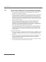
Monitoring Configuration Using Individual Messages ................................................................ 122
Glossary ................................................................................................................... 123
Tables
Table 1. PCI Operation Modes Supported by Dialogic® DSI SS7HDP Network Interface Boards . 12
Table 2. Dialogic® DSI SS7HDC Network Interface Boards Physical Interfaces ....................... 17
Table 3. Dialogic® DSI SS7HDC Network Interface Boards Port Status Indications .................. 20
Table 4. Dialogic® DSI SS7HDC Network Interface Boards Power Requirements ..................... 20
Table 5. Dialogic® DSI SS7HD License Buttons .................................................................. 27
Table 6. Relationship between License Button Codes, Run Modes and Protocol Modules .......... 28
Table 7. Protocol Dimensioning Supported by V5.07 of the Code File .................................... 30
Table 8. High Speed Link Support on Dialogic® SS7HD Network Interface Boards................... 46
Table 9. Message Summary............................................................................................. 47
Table 10. Dialogic® DSI SS7HD Network Interface Board Software Module IDs .......... 50
Table 11. Message Status Reponses ................................................................................. 52
Figures
Figure 1. CT Bus Connections .......................................................................................... 36
Figure 2. Drop and Insert ................................................................................................ 40
Figure 3. Protocol Configuration Message Sequence Diagram ............................................. 121
5
1 Introduction
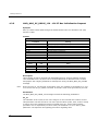
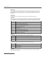
Revision History
Issue
Note:
6
Date
Description
11
April 2012
Re-structured manual. Configuration and installation details moved to
DSI Software Environment Programmer’s Manual.
10
February 2010
Updates for changes to Windows® driver support
9
September 2009
Updates for Solaris and Windows® timestamping support.
8
February 2008
Minor updates and corrections.
7
December 2007
Updates for the “Additions for PCI Express board support”.
6
September 2007
Updates for brand changes, web sites, and other minor corrections.
5
July 2006
Additions for Solaris support, Pigeon Point™ Hot Swap Kit support,
HSL functionality and enhanced message-based configuration
sequence descriptions.
4
December 2004
Updates coinciding with the release of the SS7HDCS8 and
SS7HDCN16 boards.
3
September 2004
Additions for CompactPCI production release including: run mode and
protocol dimension information, MGT_MSG_R_BRDINFO message,
information on running gctload as a service, information on received
message timestamping including the API_MSG_RX_INDT and
MGT_MSG_NTP_SYNC messages and s7_log options.
2
April 2004
Supports software release 2 for SS7HDP (PCI) boards. Additions for
Windows® support and support for running protocols other than MTP2
on the board.
1
October 2003
Supports the first production release.
The current version of this guide can be found at:
http://www.dialogic.com/support/helpweb/signaling
®
Dialogic
1
DSI SS7HD Network Interface Boards Programmer's Manual Issue 11
Introduction
Dialogic® DSI SS7HD Network Interface Boards include specialized T1/E1/J1 SS7
signaling boards for use in PCI, CompactPCI and PCI Express systems. The boards
offer a common software API to the application that enables applications to be ported
easily between hardware architectures.
The high density SS7 boards include PCI, CompactPCI and PCI Express form factors.
The CompactPCI boards are available with different rear transition modules to allow a
range of different physical interfaces options. Section 2, “Specification” on page 9
describes the options and provides details of the type and number of interfaces
supported by the PCI, CompactPCI and PCI Express boards.
The PCI, CompactPCI and PCI Express boards contain embedded signaling processors.
Each signaling processor is capable of handling up to 32 SS7 signaling links or a single
high-speed SS7 link (HSL). The selection is determined when the first or only link is
configured on a signaling processor. A single code file contains all the necessary
software and firmware.
The boards provide a suitable hardware platform for running Dialogic® DSI Protocol
Stacks for the realization of Signaling System Number 7 signaling nodes. In addition,
the DSI SS7HD boards can be used to build high performance monitoring applications.
The boards can be used under the Linux, Solaris, and Windows® operating systems.
Note:
Throughout this document, the term Windows is used to refer to the Windows Server 2003,
Windows XP Pro, Windows Vista Windows Server 2008, Windows Server 2008 R2, and
Windows 7 operating systems.
This manual is the Programmer’s Manual for the Dialogic® DSI SS7HD Network
Interface Boards range of signaling boards. It is targeted for system developers who
are integrating the boards and developing applications that use the underlying SS7
protocol stack. The manual includes information on:
•
board specification
•
DSI SS7HD specific configuration and operation of the boards and the SS7
software stack
•
message references
The manual should be used in conjunction with the appropriate Installation Guide and
Regulatory Notice for the board and the Dialogic® Distributed Signaling Interface
Components - Software Environment Programmer's Manual. These and other
supporting documentation, including the Programmer’s Manuals for the individual
protocol modules, are listed in Section 1.1, “Related Information” on page 7.
Note:
1.1
Users of the SS7MD, SS7LD, SPCI4 and SPCI2S Network Interface Boards should refer to
separate documentation that covers those boards.
Related Information
Refer to the following for related information:
•
Dialogic® SS7HDP and SS7HDE Board Installation Guide
•
Dialogic® SS7HDP Regulatory Notices
•
Dialogic® SS7HDC Boards Installation Guide
7
1 Introduction
•
Dialogic® SS7HDC Regulatory Notices
•
Dialogic® SS7HDE Regulatory Notices
•
Dialogic® Distributed Signaling Interface Components - Software Environment
Programmer's Manual
•
Dialogic® SS7 Protocols MTP2 Programmer’s Manual
•
Dialogic® SS7 Protocols MTP3 Programmer’s Manual
•
Dialogic® SS7 Protocols ISUP Programmer’s Manual
•
Dialogic® SS7 Protocols TUP Programmer’s Manual
•
Dialogic® SS7 Protocols SCCP Programmer’s Manual
•
Dialogic® SS7 Protocols TCAP Programmer’s Manual
•
Dialogic® SS7 Protocol Stack MAP Programmer’s Manual
•
Dialogic® SS7 Protocols INAP Programmer’s Manual
•
Dialogic® SS7 Protocols IS41 Programmer’s Manual
•
Dialogic® DSI Signaling Servers Manual
•
Dialogic® DSI Protocol Stacks SNMP User Manual
•
Dialogic® DSI Protocol Stacks - Host Licensing User Guide
Current software and documentation supporting Dialogic® DSI products is available at
http://www.dialogic.com/support/helpweb/signaling.
8
®
Dialogic
2
DSI SS7HD Network Interface Boards Programmer's Manual Issue 11
Specification
This section provides information about:
• Product Identifiers
• Dialogic® DSI SS7HDP Network Interface Board - PCI Form Factor Products
• Dialogic® DSI SS7HDC Network Interface Board - CompactPCI Form Factor
Products
• Dialogic® DSI SS7HDE Network Interface Board - PCI Express Form Factor
Products License Buttons
2.1
Product Identifiers
The Dialogic® DSI SS7HD Network Interface Boards product family includes the PCI,
CompactPCI and PCI Express form factor boards described in the following subsections.
2.1.1
Dialogic® DSI SS7HDP Network Interface Boards - PCI Form
Factor Products
DSI SS7HDP PCI form factor products include the following:
•
SS7HDPD4TEW
A PCI board with dual signaling processors and 4 T1/E1/J1 ports, supporting up to 64
SS7 links or up to two SS7 HSL links
The number of signaling processors supported on each board determines the maximum
number of links that can be supported. The signaling processor CPU controls Message
Transfer Part 2 (MTP2) protocol operation of the board. Each board also contains a
main CPU that handles the board management and monitoring functions.
2.1.2
Dialogic® DSI SS7HDC Network Interface Boards - CompactPCI
Form Factor Products
DSI SS7HDC CompactPCI form factor products include the following:
•
SS7HDCQ16W
A CompactPCI board with quad signaling processors and 16 T1/E1/J1 (provided by a
companion Rear Transition Module), supporting up to 128 SS7 links or up to four SS7
HSL links.
•
SS7HDCD16W
A CompactPCI board with dual signaling processors and 16 T1/E1/J1 ports (provided
by a companion Rear Transition Module), supporting up to 64 SS7 links or up to two
SS7 HSL links.
•
SS7HDCS8W
A CompactPCI board with a single signaling processor and 8 T1/E1/J1 ports (provided
by a companion Rear Transition Module), supporting up to 32 SS7 links or one SS7
HSL link.
•
SS7HDCN16W
9
2 Specification
A CompactPCI line interface board providing 16 T1/E1/J1 ports (provided by a
companion Rear Transition Module).
The number of signaling processors supported on each board determines the maximum
number of links that can be supported. The signaling processor CPU controls Message
Transfer Part 2 (MTP2) protocol operation of the board. Each board also contains a
main CPU that handles the board management and monitoring functions.
For the CompactPCI boards, the rear transition modules that are available are:
•
SS7HDCR8TEW
SS7 CompactPCI Rear Transition Module with 8 T1/E1/J1 ports
•
SS7HDCR16TEW
SS7 CompactPCI Rear Transition Module with 16 T1/E1/J1 ports
All CompactPCI boards interoperate with all rear transition modules. See Section 2.3.4,
“Rear Transition Modules” on page 18 for more information.
2.1.3
Dialogic® DSI SS7HDE Network Interface Boards - PCI Express
Form Factor Products
DSI SS7HDE PCI Express form factor products include the following:
•
SS7HDED4TEQ
A PCI Express board with dual signaling processors and 4 T1/E1/J1 ports, supporting
up to 64 SS7 links or up to two SS7 HSL links.
The number of signaling processors supported on each board determines the maximum
number of links that can be supported. The signaling processor CPU controls Message
Transfer Part 2 (MTP2) protocol operation of the board. Each board also contains a
main CPU that handles the board management and monitoring functions.
10
®
Dialogic
DSI SS7HD Network Interface Boards Programmer's Manual Issue 11
Dialogic® DSI SS7HDP Network Interface Board - PCI
Form Factor Products
2.2
The DSI SS7HDP board (SS7HDPD4TEW) is a full-length universal expansion PCI board
that supports 3.3V/5V signaling environments, a 64/32-bit bus width, and a bus speed
of 66/33 MHz. Features of the DSI SS7HDP board are described in the following topics:
2.2.1
•
Capacity
•
Host Interface
•
Physical Interfaces
•
Protocol Resource Support
•
Visual Indicators
•
Power Requirements
•
Environmental Specification
•
Safety, EMC and Telecommunications Specifications
•
Reliability
Capacity
The capacity of DSI SS7HDPD4TEW boards is described as follows:
•
•
Digital interfaces
—
Four T-1 or E-1 (software selectable)
—
High impedance selectable
SS7 links
Terminate or monitor up to 64 links or up to two HSL links per board
Note:
In order to monitor both directions of a signaling link, the user must separately connect
each direction of the signaling link to the receive connection of two different LIUs on the DSI
SS7HD board.
•
SS7 protocols
MTP2 on board (16 link and 64 link options), others on host
•
TDM bus
H.100 CT Bus compliant with ECTF H.100 CT Bus
•
Processors
—
Network: Intel 80200 processor
—
Signaling: Up to two Intel 80321 I/O processors
11
2 Specification
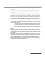
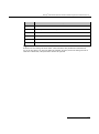
2.2.2
Host Interface
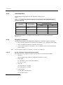
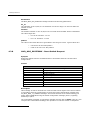
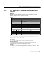
DSI SS7HDP boards support the PCI operation modes given in
Table 1.
Table 1. PCI Operation Modes Supported by Dialogic® DSI SS7HDP Network
Interface Boards
Signaling Environment
Bus Width
Bus Clock Rate
3.3 V
5V
32-bit
33 MHz
Yes
Yes
32-bit
66 MHz
Yes
No
64-bit
33 MHz
Yes
Yes
DSI SS7HDP boards are compatible with the PCISIG PCI Local Bus Specification
Revision 2.2.
2.2.3
Physical Interfaces
The DSI SS7HDP board (SS7HDPD4TEW) supports the following physical interfaces:
Note:
2.2.3.1
•
Four T1/E1/J1 digital trunk interfaces. See Section 2.2.3.1 below for more detail.
•
One 10/100Base-TX Ethernet interface (RJ-45 port)
•
H.100 CT Bus interface. See Section 3.4.1 for details on the correct termination
of the CT Bus.
The 10/100Base-TX Ethernet interface is currently not supported.
T1/E1/J1 Digital Trunk Interface Properties
The properties of the T1/E1/J1 digital trunk interfaces are described as follows:
•
Standard
Four interfaces each software configurable as either T1 or E1
•
Pulse mask
T1: TIA-968-A, CS-03, and AT&T TR62411
E1: ITU-T G.703
•
Data rate
T1: 1544 kbits/s ± 50 ppm
E1: 2048 kbits/s ± 50 ppm
•
Frame format
T1: D4, ESF, and ESF-CRC6
E1: E1 and E1-CRC4
12
®
Dialogic
•
DSI SS7HD Network Interface Boards Programmer's Manual Issue 11
Line codes
HDB3, AMI (ZCS), AMI, B8ZS
•
Connector type
RJ-45
2.2.4
Protocol Resource Support
When used in a signaling node, the DSI SS7HDP board (SS7HDPD4TEW) supports the
Message Transfer Part (MTP) running on the board (with support for up to 64 links or
two HSL links) and optionally other protocols including ISUP, TUP, SCCP, TCAP, MAP,
INAP and IS41 running on the board or the host. The protocols are enabled by license
buttons that are specific to DSI SS7HD boards and are engraved with the codes BC,
BD, BE and BF. See Section 2.5, “License Buttons” on page 27.
The DSI SS7HDP board supports passive monitoring of HDLC format data links
including, for example, SS7, LAPB, LAPD, ISDN and DPNSS. In this mode, the received
messages are directly reported to the application. For more information on link
monitoring, see Section 3.3, “Monitoring” on page 33.
It is possible to use monitor and receive-transmit protocol operations concurrently on
the same signaling board.
2.2.5
Visual Indicators
The DSI SS7HDP board (SS7HDPD4TEW) includes the following visual indicators:
•
Note:
2.2.6
—
Ethernet Port Integrity (Green)
—
Ethernet Port Activity (Amber)
The 10/100Base-TX Ethernet interface is currently not supported.
•
Note:
Two LEDs that are integrated into the Ethernet RJ-45 port:
Three general purpose LEDs (CR1, CR2, and CR3)
The general purpose LEDs are not visible when the board is fully installed in a chassis with
the cover on, but are intended for use during development.
Power Requirements
Power requirements are described as follows:
•
+5VDC power
5A maximum, 3A typical
2.2.7
Physical Specification
Form factor
PCI, Universal, 64 bit
13
2 Specification
Dimensions
Board
Length
312 mm (12.283 inches) – excludes ISA Retainer
Height
106.68 mm (4.20 inches)
Packaged
Length
406 mm ( 15.98 inches)
Width
220 mm (8.66 inches)
Height
45 mm (1.77 inches)
Weight
2.2.8
Board
332 g
Packaged Board
680 g
Environmental Specification
Environmental specification is described as follows:
•
Operating temperature range
+5°C to +40°C
•
Storage temperature range
-20° C to +40° C
•
Humidity
5 to 85% non-condensing
•
Altitude
197 ft (60 m) below sea level to 5,905 ft (1800 m) above sea level
•
Vibration
0.1 g, 5 to 100 Hz
•
Shock
Packaged equipment drop test 29.5 in (750 mm)
2.2.9
Safety, EMC and Telecommunications Specifications
Safety, EMC and telecommunications specification information is provided by the
following:
•
DSI SS7HDP Regulatory Notices
Supplied with each product and provide a full list of the specifications to which DSI
SS7HDP boards conform.
•
International Declaration of Conformity
See http://www.dialogic.com/declarations.
14
®
Dialogic
•
DSI SS7HD Network Interface Boards Programmer's Manual Issue 11
Country-Specific Approvals
See the Global Product Approvals list at http://www.dialogic.com/declarations.
Alternatively, contact your Dialogic technical sales representative for more information.
2.2.10
Reliability
Product reliability is described by:
•
MTBF Predication
135,000 hours as per the Bellcore method @ 40°C
•
Warranty
See Dialogic® Telecom Products Warranty Information at
http://www.dialogic.com/warranties.
15
2 Specification
Dialogic® DSI SS7HDC Network Interface Board CompactPCI Form Factor Products
2.3
DSI SS7HDC boards are high-density, high performance, multi-port, SS7 signaling
interface boards designed for use in telecommunications environments. The boards
have quad, dual, single or no signal processor(s) and support multiple HDLC-based
signaling channels, including up to 128 SS7 links that can operate at 64, 56, and 48
kbits/s. The boards are 64-bit CompactPCI boards and operate with Rear Transition
Modules (RTMs) that provide external connections. Features of the DSI SS7HDC board
are described in the following topics:
2.3.1
•
Capacity
•
Host Interface
•
Physical Interfaces
•
Rear Transition Modules
•
Protocol Resource Support
•
Visual Indicators
•
Power Requirements
•
Environmental Specifications
•
Safety, EMC and Telecommunications Specifications
•
Reliability
Capacity
The capacity of DSI SS7HDC boards is described as follows:
•
•
Note:
16
Digital interfaces
—
Eight ports for SS7HDCS8W. Eight or 16 ports for SS7HDCN16W,
SS7HDCD16W and SS7HDCQ16W with the corresponding RTM.
—
T-1 or E-1 (software selectable)
—
High impedance selectable
SS7 links
—
On SS7HDCQ16W boards, terminate or monitor up to 128 bidirectional
links or up to four HSL links per board
—
On SS7HDCD16W boards, terminate or monitor up to 64 bidirectional
links or up to two HSL links per board
—
On SS7HDCS8W boards, terminate or monitor up to 32 bidirectional links
or one HSL link per board
—
On SS7HDCN16W boards, SS7 links are not supported. This board is for
use as a line interface board to provide additional T1/E1/J1 connectivity.
In order to monitor both directions of a signaling link, the user must separately connect
each direction of the signaling link to the receive connection of two different LIUs on the DSI
SS7HD board.
®
Dialogic
•
DSI SS7HD Network Interface Boards Programmer's Manual Issue 11
SS7 protocols
MTP2 runs on the board. MTP3, ISUP, TUP, SCCP, TCAP, MAP, INAP and IS41 can be
configured to run on the board or on the host.
•
TDM bus
H.110 CT Bus compliant with ECTF H.110 Hardware Compatibility Specification: CT
Bus, Rev. 1.0.
•
2.3.2
Processors
—
Network: Intel 80200 processor
—
Signaling: Intel 80321 I/O processor On SS7HDCD16W boards, dual
Intel 80321 I/O processors. On SS7HDCS8W boards a single Intel 80321
I/O processor. On SS7HDCN16W boards, no signaling processors are
available.
Host Interface
The DSI SS7HDC boards support the following host interfaces:
2.3.3
•
PCI 32-bit @ 33MHz
•
PCI 64-bit @ 33MHz
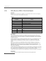
Physical Interfaces
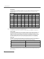
The DSI SS7HDC main boards support the physical interfaces described in the
following table. The T1/E1/J1 interfaces also require the use of a companion Rear
Transition Module (RTM) as described in Section 2.3.4, “Rear Transition Modules” on
page 18.
Table 2. Dialogic® DSI SS7HDC Network Interface Boards Physical Interfaces
DSI SS7HDC CompactPCI Variant
Interface
S8
2.3.3.1
Q16, D16, N16
T1/E1/J1
8 (SS7HDCR8TEW required)
8 (SS7HDCR8TEW required)
OR
16 (SS7HDCR16TEW required)
CT Bus
H.110
H.110
T1/E1/J1 Digital Trunk Interface Properties
The properties of the T1/E1/J1 digital trunk interfaces are described as follows:
•
Standard
SS7HDCQ16W, SS7HDCD16W, SS7HDCS8W and SS7HDCN16W boards provide up to
sixteen interfaces. Each interface is software configurable as either T1 or E1.
•
Pulse mask
—
T1: TIA-968-A, CS-03, and AT&T TR62411
—
E1: ITU-T G.703
17
2 Specification
•
•
•
Data rate
—
T1: 1544 kbits/s ± 50 ppm
—
E1: 2048 kbits/s ± 50 ppm
Frame format
—
T1: D4, ESF, and ESF-CRC6
—
E1: E1 and E1-CRC4
Line codes
— HDB3, AMI (ZCS), AMI, B8ZS
•
Connector type
The connector type is determined by the RTM used, as defined in Section 2.3.4, “Rear
Transition Modules” on page 18.
2.3.3.2
V.11 Interface Properties
The properties of the V.11 interfaces are described as follows:
•
Standard
Eight V.11 interfaces on all SS7HDC boards
•
Compatibility
Compatible with ITU-T V.11 balanced, double current, interface circuits
•
Data rate
Configurable as 48 kbits/s, 56 kbits/s or 64 kbits/s on a per port basis. Also, features a
configureable clock source on a per port basis; the transmit and receive data circuits
can be independentantly configured to be clocked from either a locally generated clock
or from the received clock circuit.
•
Connector type
Provided on the SS7HDCR8S Rear Transition Module via two 37-way D-type connectors
(sockets), each providing access to four V.11 interfaces. Not available on the
SS7HDCR8TE or SS7HDCR16TE RTMs.
2.3.4
Rear Transition Modules
For a T1/E1/J1 interface, a Rear Transition Module (RTM) should be selected to provide
the physical connectivity required, with regard to the number of ports and connector
type:
•
SS7HDCR8TEW provides for up to 8 T1/E1/J1 physical interfaces
•
SS7HDCR16TEW provides for up to 16 T1/E1/J1 physical interfaces
The properties of the physical interfaces on the RTMs are described as follows:
•
18
Connector type
—
SS7HDCR8TEW contains eight individual RJ-45 connectors
—
SS7HDCR16TEW contains two RJ-48M connectors, each providing 8
T1/E1/J1ports
®
Dialogic
2.3.5
DSI SS7HD Network Interface Boards Programmer's Manual Issue 11
Protocol Resource Support
When used in a signaling node, the DSI SS7HDC boards support the Message Transfer
Part (MTP) running on the board and optionally other protocols including ISUP, TUP,
SCCP, TCAP, MAP, INAP and IS41 running on the board or the host. The protocols are
enabled by a range of license buttons engraved with the codes BC, BD, BE and BF. See
Section 2.5, “License Buttons” on page 27.
DSI SS7HDC boards support passive monitoring of HDLC format data links including,
for example, SS7, LAPB, LAPD, ISDN and DPNSS. In this mode, the received messages
are directly reported to the application. For more information on link monitoring, see
Section 3.3, “Monitoring” on page 33.
It is possible to use monitor and receive-transmit protocol operations concurrently on
the same signaling board.
2.3.6
Visual Indicators
The DSI SS7HDC boards include the following visual indicators:
•
Power On indicator (Green)
•
Four General Purpose LEDs (CR1, CR2, CR3 and CR4) for use by application
developers (see Section 4.3.13, “MVD_MSG_LED_CTRL - LED Control Request”
on page 93 for more information)
•
Port Status indicators (4 for each T1/E1/J1 port, see Section 2.3.6.1 following)
•
Hotswap indicator (Blue)
The companion Rear Transition Modules (RTMs) include the following visual indicators:
•
Two LEDs that are integrated into each Ethernet RJ-45 port:
—
Ethernet Port Integrity (Green)
—
Ethernet Port Activity (Amber)
The SS7HDCR8TEW Rear Transition Module (RTM) has the following additional visual
indicators:
•
Note:
2.3.6.1
Two Ethernet Port Speed indicators (Green) that indicate the mode in which the
port operates, 100BaseT (On) or 10BaseT (Off).
The 10/100Base-TX Ethernet interface is currently not supported.
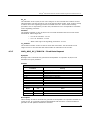
Port Status Indicators
The DSI SS7HDC boards include a set of four LEDs for each T1/E1/J1 port that provide
a status indication for the respective port. The red Loopback LED when lit indicates
that the respective trunk is in loopback mode. The green, yellow and red LEDs indicate
normal operation or Carrier Failure Alarms (CFAs) as indicated in the following table.
19
2 Specification
Table 3. Dialogic® DSI SS7HDC Network Interface Boards Port Status
Indications
Green
2.3.7
Yellow
Red
Condition
On
Off
Off
Normal operation
Off
Off
On
Loss of Signal (LOS)
On
Off
On
Red alarm
On
On
Off
Yellow Alarm/Remote Alarm Indicator (RAI)
On
On
On
Alarm Indicator Signal (AIS)
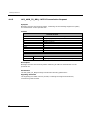
Power Requirements
Power requirements for DSI SS7HDC boards are described in the following table
Table 4. Dialogic® DSI SS7HDC Network Interface Boards Power
Requirements
Dialogic® DSI SS7HDC
Board Model
SS7HDCQ16W
SS7HDCD16W
SS7HDCS8W
SS7HDCN16W
Note:
2.3.8
Power Supply
+5V DC
2.3 A
+3.3V DC
4.5 A
+5V DC
1.3 A
+3.3V DC
4.2 A
+5V DC
0.9 A
+3.3V DC
2.6 A
+5V DC
0.4 A
+3.3V DC
4.0 A
Current consumption figures include the use of an appropriate rear transition module.
Environmental Specifications
Environmental specification is described as follows:
•
Operating temperature range
+5°C to +40°C
•
Storage temperature range
-20° C to +40° C
20
Max. Rating
®
Dialogic
•
DSI SS7HD Network Interface Boards Programmer's Manual Issue 11
Humidity
5 to 85% non-condensing
•
Altitude
197 ft (60 m) below sea level to 5,905 ft (1800 m) above sea level
•
Vibration
0.1 g, 5 to 100 Hz
•
Shock
Packaged equipment drop test 29.5 in (750 mm)
2.3.9
Safety, EMC and Telecommunications Specifications
Safety, EMC and telecommunications specification information is provided by the
following:
•
DSI SS7HDC Regulatory Notices
Supplied with each product and provide a full list of the specifications to which DSI
SS7HDC boards conform.
•
International Declaration of Conformity
See http://www.dialogic.com/declarations.
•
Country-Specific Approvals
See the Global Product Approvals list at http://www.dialogic.com/declarations.
Alternatively, contact your Dialogic technical sales representative for more information.
2.3.10
Reliability
Product reliability is described by:
•
MTBF Predication
MTBF prediction values for the DSI SS7HDC boards, as per the Bellcore method @
40°C, are:
—
SS7HDCD8 board: 122,800 hours
—
SS7HDCQ8 board: 90,300 hours
—
SS7HDCQ16W board: 76,000 hours
—
SS7HDCD16W board: 90,300 hours
—
SS7HDCS8W board: 129,600 hours
—
SS7HDCN16W board: 123,900 hours
MTBF prediction values for RTMs, as per the Bellcore method @ 40°C, are:
•
—
SS7HDCR8TEW RTM: 1,215,800 hours
—
SS7HDCR16TEW RTM: 839,000 hours
—
SS7HDCR8S RTM: 901,900 hours
Warranty
21
2 Specification
See Dialogic® Telecom Products Warranty Information at
http://www.dialogic.com/warranties.
22
®
Dialogic
DSI SS7HD Network Interface Boards Programmer's Manual Issue 11
Dialogic® DSI SS7HDE Network Interface Board - PCI
Express Form Factor Products
2.4
The DSI SS7HDE board (SS7HDED4TEQ) is a PCI Express form factor, x4 link width,
standard height, full length board.
Features of the DSI SS7HDE board are described in the following topics:
2.4.1
•
Capacity
•
Host Interface
•
Physical Interfaces
•
Protocol Resource Support
•
Visual Indicators
•
Power Requirements
•
Environmental Specification
•
Safety, EMC and Telecommunications Specifications
•
Reliability
Capacity
The capacity of DSI SS7HDED4TEQ boards is described as follows:
•
•
Digital interfaces
—
Four T-1 or E-1 (software selectable)
—
High impedance selectable
SS7 links
Terminate or monitor up to 64 links or up to two HSL links per board
Note:
In order to monitor both directions of a signaling link, the user must separately connect
each direction of the signaling link to the receive connection of two different LIUs on the DSI
SS7HD board.
•
SS7 protocols
MTP2 on board (16 link and 64 link options), others on host
•
TDM bus
H.100 CT Bus compliant with ECTF H.100 CT Bus
•
2.4.2
Processors
—
Network: Intel 80200 processor
—
Signaling: Up to four Intel 80321 I/O processors
Host Interface
DSI SS7HDE boards have a x4 PCI Express connector, and will scale to x4, x2 or x1
lanes via automatic link training. They can also be installed in a x8 or x16 PCI Express
slot.
23
2 Specification
2.4.3
Physical Interfaces
The DSI SS7HDE board (SS7HDED4TEQ) supports the following physical interfaces:
Note:
2.4.3.1
•
Four T1/E1/J1 digital trunk interfaces. See Section 2.4.3.1 below for more detail.
•
One 10/100Base-TX Ethernet interface (RJ-45 port)
•
H.100 CT Bus interface. See Section 3.4.1 for details on the correct termination
of the CT Bus.
The 10/100Base-TX Ethernet interface is currently not supported.
T1/E1/J1 Digital Trunk Interface Properties
The properties of the T1/E1/J1 digital trunk interfaces are described as follows:
•
Standard
Four interfaces each software configurable as either T1 or E1
•
•
•
•
Pulse mask
—
T1: TIA-968-A, CS-03, and AT&T TR62411
—
E1: ITU-T G.703
Data rate
—
T1: 1544 kbits/s ± 50 ppm
—
E1: 2048 kbits/s ± 50 ppm
Frame format
—
T1: D4, ESF, and ESF-CRC6
—
E1: E1 and E1-CRC4
Line codes
—
•
Connector type
—
2.4.4
HDB3, AMI (ZCS), AMI, B8ZS
RJ-45
Protocol Resource Support
When used in a signaling node, the DSI SS7HDE board (SS7HDED4TEQ) supports the
Message Transfer Part (MTP) running on the board (with support for up to 64 links or
two HSL links) and optionally other protocols including ISUP, TUP, SCCP, TCAP, MAP,
INAP and IS41 running on the board or the host. The protocols are enabled by license
buttons that are specific to SS7HD boards and are engraved with the codes BC, BD, BE
and BF. See Section 2.5, “License Buttons” on page 27.
The DSI SS7HDE board supports passive monitoring of HDLC format data links
including, for example, SS7, LAPB, LAPD, ISDN and DPNSS. In this mode, the received
messages are directly reported to the application. For more information on link
monitoring, see Section 3.3, “Monitoring” on page 33.
It is possible to use monitor and receive-transmit protocol operations concurrently on
the same signaling board.
24
®
Dialogic
2.4.5
DSI SS7HD Network Interface Boards Programmer's Manual Issue 11
Visual Indicators
The DSI SS7HDE board (SS7HDPD4TEW) includes the following visual indicators:
•
Note:
Two LEDs that are integrated into the Ethernet RJ-45 port:
2.4.6
Ethernet Port Integrity (Green)
—
Ethernet Port Activity (Amber)
The 10/100Base-TX Ethernet interface is currently not supported.
•
Note:
—
Three general purpose LEDs (CR1, CR2, and CR3)
The general purpose LEDs are not visible when the board is fully installed in a chassis with
the cover on, but are intended for use during development.
Power Requirements
Power requirements are described as follows:
•
+12VDC power
1.6A maximum, 1.35A typical
•
+3.3VDC power
0.5A maximum, 0.27A typical
2.4.7
Physical Specification
Form factor
PCIe, x4 lane, standard height, full length
Dimensions
Board
Length
312 mm (12.283 inches) – excludes ISA Retainer
Height
106.68 mm (4.20 inches)
Packaged
Length
Width
220 mm (8.66 inches)
Height
45 mm (1.77 inches)
Weight
2.4.8
406 mm ( 15.98 inches)
Board
326 g
Packaged Board
670 g
Environmental Specification
Environmental specification is described as follows:
•
Operating temperature range
25
2 Specification
—
•
Storage temperature range
—
•
0.1 g, 5 to 100 Hz
Shock
—
2.4.9
197 ft (60 m) below sea level to 5,905 ft (1800 m) above sea level
Vibration
—
•
5 to 85% non-condensing
Altitude
—
•
-20° C to +40° C
Humidity
—
•
+5°C to +40°C
Packaged equipment drop test 29.5 in (750 mm)
Safety, EMC and Telecommunications Specifications
Safety, EMC and telecommunications specification information is provided by the
following:
•
DSI SS7HDE Regulatory Notices
Supplied with each product and provide a full list of the specifications to which DSI
SS7HDE boards conform.
•
International Declaration of Conformity
See http://www.dialogic.com/declarations.
•
Country-Specific Approvals
See the Global Product Approvals list at http://www.dialogic.com/declarations.
Alternatively, contact your Dialogic technical sales representative for more information.
2.4.10
Reliability
Product reliability is described by:
•
MTBF Predication
135,000 hours as per the Bellcore method @ 40°C
•
Warranty
See Dialogic® Telecom Products Warranty Information at
http://www.dialogic.com/warranties.
26
®
Dialogic
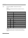
2.5
DSI SS7HD Network Interface Boards Programmer's Manual Issue 11
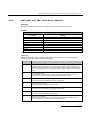
License Buttons
The DSI SS7HD code file supports different protocol module combinations that are
enabled by fitting the correct License button on the board. Each license button is
engraved with a two-letter code that is used for identification. The following table
shows Item Market Names (IMNs) for the currently available license buttons and the
two-letter code corresponding to each IMN.
Table 5. Dialogic® DSI SS7HD License Buttons
License Button IMN
Note:
2.5.1
Code
SS7SBHDFBA
BA
SS7SBHDFBC
BC
SS7SBHDFBD
BD
SS7SBHDFBE
BE
SS7SBHDFBF
BF
A license button is not required for the SS7HDCN16W board, since this board operates in
DTI run mode only. See Section 2.5.1, “Run Modes” for more information.
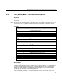
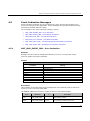
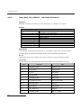
Run Modes
The run_mode parameter in either the SS7_BOARD command or the Board Reset
Request message determines the protocol modules that are started by the code file at
run time. The following table shows the relationship between the license button code,
the run mode and the protocol modules that are enabled (see Table 2 on page 26).
Note:
The SS7HDCN16W is suitable for DTI run mode only, therefore a license button is not
required.
27
2 Specification
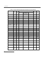
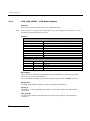
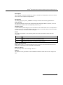
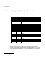
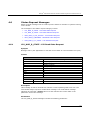
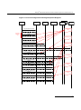
Table 6. Relationship between License Button Codes, Run Modes and Protocol Modules
Buttons
Run
Mode
Value
Run
Mode
Monitor
MTP2
MTP3
ISUP
TUP
SCCP
TCAP
MAP
No button
DTI
1
BF, BE, BD, BC,
BA
MON
17
BF, BE, BD, BC
MTP2
2
R
BF, BE, BD, BC
MTP
3
R
BF, BE, BD
MTP2-L
25
L
BF, BE, BD
MTP-L
29
L
R
BF, BE, BD
ISUP
4
R
R
BF, BE, BD
TUP
6
R
R
BF, BE, BD
SCCPCL
10
R
R
CL
BF, BE, BD
SCCPCO
11
R
R
CO
BF, BE, BD
TCAP
12
R
R
BF, BE
ISUP-L
5
L
R
BF, BE
TUP-L
7
L
R
BF, BE
TCAP-L
30
R
R
BF, BE
MAP
14
R
R
CL
R
BF, BE
IS41
15
R
R
CL
R
BF, BE
INAP
21
R
R
CL
R
BF
MAP-L
31
L
R
CL
L
BF
IS41-L
32
L
R
CL
L
BF
INAP-L
33
L
R
CL
L
BF
TCAPISUP
13
R
R
R
CL
R
BF
MAPISUP
22
R
R
R
CL
R
R
BF
MAPTUP
23
R
R
CL
R
R
BF
MAPINAP
24
R
R
CL
R
R
BF
IS41INAP
26
R
R
CL
R
BF
MAPINAPISUP
28
R
R
CL
R
Key:
Rx Only - MTP2 receive only operation
L - Large
R - Regular
28
Protocol Modules
IS41
INAP
Rx Only
R
R
R
R
L
L
L
R
R
R
R
R
L
L
L
R
R
R
R
R
CO - Connection-Oriented
CL - Connectionless
NOTE: HSL requires the use of a license button that supports the MTP2 “Large”
model, when signaling is used. The following buttons can be used: BF, BE, BD and
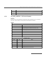
BA (monitoring only).
®
Dialogic
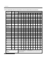
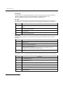
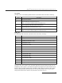
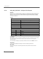
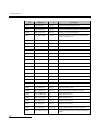
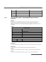
2.5.2
DSI SS7HD Network Interface Boards Programmer's Manual Issue 11
Run Modes and Protocol Dimensions
The combination of the run mode and board type determines how many SS7 links can
be supported by the board. The SS7HDCQ8 board with four signaling processors can
support twice the number of links of the other boards, which contain two signaling
processors. The number of circuits and dialogs that can be supported by a board
depends only on the run mode and not on the DSI SS7HD board variant.
The MTP protocol module is available for all run modes except DTI, MON, MTP2 and
MTP2-L. The MTP protocol module supports up to 128 Low Speed Links (LSL), 4 High
Speed Links (HSL), 64 link sets and 128 routes.
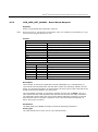
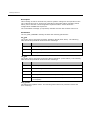
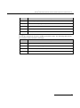
A summary of the protocol dimensioning supported by V5.07 of the code file is shown
below.
Note:
The values in this table are subject to change. Refer to the release notes for the code file
version being used.
29
2 Specification
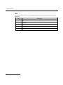
Table 7. Protocol Dimensioning Supported by V5.07 of the Code File
Buttons
Run
Mode
Run
Mode
Value
Number of Links (LSL/HSL)
SS7HDCS8W
SS7HDPD4TEW
SS7HDCQ16W
Number
of
Circuits
Number
of
Dialogs
SS7HDED4TEQ
SS7HDCD16W
30
No Button
DTI
1
N/A
N/A
N/A
BF, BE, BD, BC,
BA
MON
17
32/1
64/2
128/4
BF, BE, BD, BC
MTP2
2
8
16
32
BF, BE, BD, BC
MTP
3
8
16
32
BF, BE, BD
MTP2-L
25
32/1
64/2
128/4
BF, BE, BD
MTP-L
29
32/1
64/2
128/4
BF, BE, BD
ISUP
4
8
16
32
8,192
BF, BE, BD
TUP
6
8
16
32
8,192
BF, BE, BD
SCCPCL
10
8
16
32
BF, BE, BD
SCCPCO
11
8
16
32
BF, BE, BD
TCAP
12
8
16
32
BF, BE
ISUP-L
5
32/1
64/2
128/4
32,768
BF, BE
TUP-L
7
32/1
64/2
128/4
32,768
BF, BE
TCAP-L
30
8
16
32
32,768
BF, BE
MAP
14
8
16
32
8,192
BF, BE
IS41
15
8
16
32
8,192
BF, BE
INAP
21
8
16
32
8,192
BF
MAP-L
31
32/1
64/2
128/4
32,768
BF
IS41-L
32
32/1
64/2
128/4
32,768
BF
INAP-L
33
32/1
64/2
128/4
32,768
BF
TCAPISUP
13
8
16
32
8,192
8,192
BF
MAPISUP
22
8
16
32
8,192
8,192
BF
MAPTUP
23
8
16
32
8,192
8,192
BF
MAPINAP
24
8
16
32
8,192
BF
IS41INAP
26
8
16
32
8,192
BF
MAPINAPISUP
28
8
16
32
Rx Only
8,192
8,192
8,192
®
Dialogic
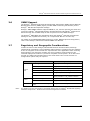
2.6
DSI SS7HD Network Interface Boards Programmer's Manual Issue 11
SNMP Support
The Dialogic® Distributed Structured Management Information (DSMI) Simple Network
Management Protocol (SNMP) Agent provides SNMP monitoring functionality for the
Dialogic® DSI SS7 Development Package.
Dialogic® DSMI SNMP software supports SNMP V1, V2, and V3 reporting the state and
events for Dialogic® DSI SS7HD Network Interface Boards and Dialogic® DSI Protocol
Stacks through use of SNMP traps as well as queries from an SNMP manager.
The Dialogic® DSMI MIBs are distributed within the Dialogic® DSI SS7 Development
Package in the /opt/DSI sub-directory as a compressed ZIP file: dsi-mibs.zip.
For details of the DSMI SNMP MIBs supported, events, SNMP traps and configuration,
refer to the Dialogic® DSI Protocol Stacks SNMP User Manual.
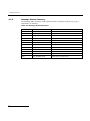
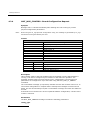
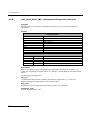
2.7
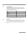
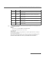
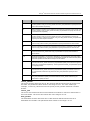
Regulatory and Geographic Considerations
Certain functions of the Dialogic® DSI SS7HD Network Interface Board, although
implemented in hardware, have selectable options that are configured by the software.
A user or integrator must consider the requirements of the application when choosing
these settings, but must also consider any local regulatory requirements for the
intended deployment location to provide a compliant overall system. As an aid to this
process, the table below details some of the areas where the correct selection of
configuration options may be required.
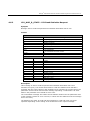
Configuration Area
T1/E1/J1
Ports
Configuration Options
Interface type
liu_type parameter in LIU_CONFIG command
Pulse shape
liu_type parameter in LIU_CONFIG command
Line code
line_code parameter in LIU_CONFIG command
Frame format
frame_format parameter in LIU_CONFIG command
CRC/E-bit operation
CRC_mode parameter in LIU_CONFIG command
Clock priorities
flags parameter in SS7_BOARD command and
options parameter in LIU_CONFIG command
Master/Slave configuration
flags parameter in SS7_BOARD command
Bus termination
flags parameter in SS7_BOARD command
Link termination or monitoring
mode
MTP_LINK or MONITOR_LINK commands
CT Bus
Links
Note:
For details on these configuration commands please refer to Dialogic® Distributed Signaling
Interface Components - Software Environment Programmer's Manual
31
3 SS7HD Board Product Specific Configuration and Operation
3
SS7HD Board Product Specific Configuration
and Operation
Before attempting software configuration, you should gain an appreciation of the
flexibility of the protocol stack, the run-time options that exist and the mechanisms
that are used to select specific features. These are explained in the Dialogic®
Distributed Signaling Interface Components - Software Environment Programmer’s
Manual which also describes the basic principles of modules and message passing.
This section provides the product specific options which are available.
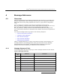
This section provides information about:
System configuration using SS7HD Board
Board Code File
Monitoring
Using the CT Bus
Received Message Timestamping
Hot Swap Operation
High Speed Link Operation
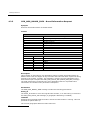
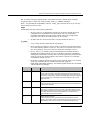
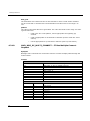
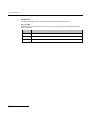
3.1
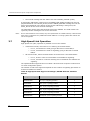
System configuration using SS7HD Boards
Some SS7 protocol modules can be run on either the host machine or on DSI SS7HD
boards. The following table shows the possible options for each protocol:
Protocol
Option
MAP, INAP, IS41
Host or board
TCAP
Host or board
ISUP, TUP, SCCP
Host or board
MTP3
Host or board
MTP2
Board only.
Host protocol software is available for Linux, Solaris SPARC, Solaris x86 and Windows®
operating systems. For more information or to purchase, contact an authorized
distributor or your account manager.
The Dialogic® DSI SS7HD Network Interface Board may be configured for most
applications using the s7_mgt utility. The s7_mgt utility is the primary tool for
configuring a DSI software stack. It is a single-shot configuration utility that takes
configuration commands from a text file (config.txt).
Details on how to configure a system using s7_mgt are provided in the Dialogic®
Distributed Signaling Interface Components - Software Environment Programmer's
Manual.
32
®
Dialogic
DSI SS7HD Network Interface Boards Programmer's Manual Issue 11
As an alternative to using s7_mgt, users can build their own configuration utilities
using messaged-based configuration. In this case users should refer to the definitions
of individual messages in Section 4, Message Reference on page 47.
The Code File contains the operating firmware for the board which is downloaded to
the board at run-time by the ssdh binary. The code file should be specified in the
SS7BOARD command in the config.txt file.
3.2
Board Code File
The DSI Network Interface Boards Code Files contain the operating software for the
DSI Network Interface Boards. The appropriate code file must be downloaded by the
host, to the board, at run-time.
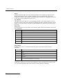
The following code files are available for the SS7HD board:
•
Note:
The ss7.dc4 code file.
The ss7.dc4 code file is distributed as part of the Dialogic® DSI Development Package.
The code file requires a host license which enables the software to run on the board,
details on how to use a Host License are given in the Dialogic® Distributed Signaling
Interface Components Host Licensing User Guide.
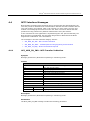
3.3
Monitoring
The monitoring option can be used in conjunction with the SS7 Development Package
for the appropriate operating system (Linux, Solaris, or Windows®) to realize a highperformance protocol monitor with up to 16 boards, each monitoring a certain number
of links (see the table in Section 2.5.2, “Run Modes and Protocol Dimensions” on page
29 for details).
When used in a passive monitoring mode, the DSI SS7HD board treats the signaling
timeslot as an HDLC channel so, in addition to SS7, other flag-idle HDLC-based
protocols may be monitored, for example LAPB, Q.931 (ISDN PRI) and DPNSS. The
protocol to be monitored must have a minimum frame length (excluding flags) of 5
octets, a maximum of 278 octets, and use the CRC polynomial (x16 + x12 + x5 + 1).
When operating in monitoring mode, the 3rd and successive identical frames may be
filtered.
It is possible to configure monitoring and terminated SS7 links on the same signaling
board.
For receive only operation, the board allows the T1/E1/J1 interfaces to be configured in
any of the following modes:
- Normal terminated impedance
- High impedance
When using High Impedance mode care should be taken to avoid long cable runs as
this can result in poor signal quality due to signal reflections.
33
3 SS7HD Board Product Specific Configuration and Operation
3.3.1
Configuration
The user needs to set up the configuration for the T1/E1/J1 interface and the operating
parameters for each link to be monitored. This can all be achieved using the config.txt
file in conjunction with the s7_mgt configuration utility. Users wishing to use discrete
message-based configuration should refer to Section A.2, “Monitoring Configuration
Using Individual Messages” on page 122 of this manual.
3.3.2
Run Time Operations
Once configured, whenever a frame is received, it is reported to the user’s application
as an API_MSG_RX_IND message.
During operation, the user may also read (and optionally reset) various statistics on a
per-link basis by sending a Link Statistics Request (DVR_MSG_R_L1_STATS) message.
3.4
Using the CT Bus
The Dialogic® DSI SS7HD Network Interface Boards support multiple T1/E1/J1 Line
Interface Units (LIUs) and a CT Bus interface (H.100 or H.110). The on-board signaling
processor handles the SS7 signaling timeslots, while the remaining circuits (voice or
data bearer circuits) are passed to the CT Bus for distribution to other boards.
Note:
The DSI SS7HDCN16W board has no signaling processors and therefore all timeslots
configured are typically terminated for connection to the H.110 CT Bus.
All communication between the application and the board is message based. Initial
configuration is typically handled by the s7_mgt protocol configuration utility that takes
commands from the config.txt protocol configuration file and generates all the
necessary configuration messages for the board. Subsequent operation is entirely
message driven; messages being passed in both directions between the board and the
application.
One of the roles of the application is to control the dynamic switching between the CT
Bus and the T1/E1/J1 line interfaces. This section provides details of how to interface
with the CT Bus, including the initial (static) configuration and the subsequent
(dynamic) switching.
The operation of the CT Bus switching interface is described in terms of the SCbus
switching model using:
34
•
MVD_MSG_SC_DRIVE_LIU, MVD_MSG_SC_LISTEN and MVD_MSG_SC_FIXDATA
messages
•
LIU_SC_DRIVE and SCBUS_LISTEN config.txt commands
®
Dialogic
3.4.1
DSI SS7HD Network Interface Boards Programmer's Manual Issue 11
Termination of the CT Bus
Dialogic® DSI SS7HDP Network Interface Boards - PCI Form Factor Products and
Dialogic® DSI SS7HDE Network Interface Boards - PCI Express Form Factor Products
must have their CT Bus termination parameter configured according to their position
on the CT Bus cable. The connectors at the two ends of the CT Bus cable must not be
left disconnected. For a DSI SS7HDP PCI board or a DSI SS7HDE PCI Express board
that is connected to an end connector on the CT Bus cable, it must be configured to
terminate the CT Bus. For a DSI SS7HDP PCI board or a DSI SS7HDE PCI Express
board connected to a mid connector on the CT Bus cable, or not connected at all, it
must be configured to not terminate the CT Bus. This can be achieved using the
SS7_BOARD command (Dialogic® Distributed Signaling Interface Components Software Environment Programmer's Manual, bit 3 in the flags parameter), the
MGT_MSG_CONFIG0 message (Section 4.2.4, “MGT_MSG_CONFIG0 - Board
Configuration Request” on page 60, bit 3 in the ll_flags parameter) or the
MVD_MSG_CNFCLOCK message (Section 4.3.11, “MVD_MSG_CNFCLOCK - Configure
Clock Request” on page 88, clk_term parameter).
3.4.2
Switching Model
The basic switching model assumes that at system initialization all incoming T1/E1/J1
timeslots and all resource board output timeslots are connected to channels on the CT
Bus and that these connections are never changed. This scheme has the advantage
that once the on-board CT Bus drivers have been set up, they are never changed
reducing the chances of inadvertently causing CT Bus conflict. It also means that the
user can predict the exact CT Bus channels where any input timeslot can be located,
which in turn can assist with fault diagnosis and general system test.
It is also possible to generate fixed patterns on any T1/E1/J1 output timeslots to
provide the correct Idle pattern for presentation to the network on all circuits where
there is no active call.
Having completed system initialization, all drives to the CT Bus are set up. Then, on a
dynamic (call-by-call) basis, the connectivity must be modified when a new call arrives
and when it finishes.
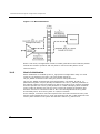
When a new call arrives, typically the application will need to initiate two listen
commands as follows:
•
One command causes the resource to listen to the appropriate CT Bus channel to
hear the incoming voice path.
•
The other command causes the T1/E1/J1 interface to listen to the output from
the resource board to generate the outgoing voice path
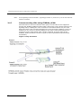
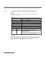
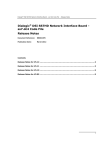
Figure 1shows the function of the commands.
35
3 SS7HD Board Product Specific Configuration and Operation
Figure 1. CT Bus Connections
When a call clears, the application needs to initiate generation of the fixed Idle pattern
towards the network operation and may wish to connect an Idle pattern to the
resource board.
3.4.3
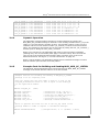
Static Initialization
Static initialization is handled by the s7_mgt protocol configuration utility. For each
T1/E1/J1 Line Interface Unit (LIU), the user should include an
LIU_SC_DRIVE command in the config.txt protocol configuration file.
The LIU_SC_DRIVE command has several parameters. The board_id and liu_id
parameters together uniquely identify the affected LIU. The sc_channel parameter is
the channel number of the first channel on the CT Bus that is to be used for timeslots
from the specified LIU. The ts_mask parameter is a mask identifying which timeslots
on the T1/E1/J1 interface are carrying voice circuits (as opposed to signaling) and
therefore need to be connected to the CT Bus. The least significant bit of ts_mask
should always be 0 when driving from an T1/E1/J1 interface.
As an example, consider a two board system where the first board has four E1 ports
and the second board has four T1 ports. We allow the first 512 CT Bus channels to be
used by other boards in the system and therefore start at sc_channel 512.
36
®
Dialogic
LIU_SC_DRIVE
LIU_SC_DRIVE
LIU_SC_DRIVE
LIU_SC_DRIVE
LIU_SC_DRIVE
LIU_SC_DRIVE
LIU_SC_DRIVE
LIU_SC_DRIVE
3.4.4
0
0
0
0
1
1
1
1
0
1
2
3
0
1
2
3
512
542
572
602
632
655
678
701
0xfffefffe
0xfffefffe
0xfffefffe
0xfffefffe
0x00fffffe
0x00fffffe
0x00fffffe
0x00fffffe
*
*
*
*
*
*
*
*
30
30
30
30
23
23
23
23
DSI SS7HD Network Interface Boards Programmer's Manual Issue 11
E1
E1
E1
E1
T1
T1
T1
T1
voice
voice
voice
voice
voice
voice
voice
voice
ccts
ccts
ccts
ccts
ccts
ccts
ccts
ccts
on
on
on
on
on
on
on
on
ts 1..15 & 17..31
ts 1..15 & 17..31
ts 1..15 & 17..31
ts 1..15 & 17..31
timeslots 1..23
timeslots 1..23
timeslots 1..23
timeslots 1..23
Dynamic Operation
The application controls dynamic changes to CT Bus switching by sending the
MVD_MSG_SC_LISTEN message to the board. This message contains the liu_id (in the
range 0 to one less than the number of LIUs), the timeslot number on the T1/E1/J1
interface and the CT Bus channel number (sc_channel) to which the timeslot should
listen. The message is directed to the correct board by calling the GCT_set_instance( )
function prior to calling the GCT_send( ) function.
When a new call arrives, the application will need to issue two listen commands
(although they will not necessarily both apply to the SS7 board). One connects the
voice circuit in the forward direction and the other connects voice circuit in the
backward direction. See Figure 1, “CT Bus Connections” on page 36.
When a call terminates, the application should issue a fixed data message to ensure
that the network port sees the voice Idle pattern.
3.4.5
Example Code for Building and Sending MVD_MSG_SC_LISTEN
The following code demonstrates how to build and send an MVD_MSG_SC_LISTEN
message to an SS7HD board to listen to a CT Bus timeslot.
/*
* Example function for building and sending an MVD_MSG_SC_LISTEN
* message to an SS7 signaling card.
*
* The only change that the user needs to make is to fill in the
* OUR_MOD_ID definition below so that is equal to the module_id
* of the application module.
*/
#define OUR_MOD_ID
#include
#include
#include
#include
#include
#include
"system.h"
"msg.h"
"libc.h"
"sysgct.h"
"pack.h"
"ss7_inc.h"
(0xef)
/*
/*
/*
/*
/*
/*
Definitions of u8, u16 etc */
Definitions of HDR, MSG etc */
Used only for memset prototype */
Prototypes for GCT_xxx */
Prototypes for rpackbytes */
Message & module definitions */
/*
* Macro to generate the value for use in the rsp_req field of the
* message header in order to request a confirmation message:
*/
#define RESPONSE(module)
(((unsigned short) 1) << ((module) & 0x0f))
/*
37
3 SS7HD Board Product Specific Configuration and Operation
* Function to drive an SCbus / CT Bus timeslot
* onto a timeslot on a PCM port:
*/
int listen_to_scbus(board_id, liu_id, timeslot, sc_channel)
int board_id;
/* board_id (0, 1, 2 ...) */
int liu_id;
/* PCM port id (0 .. one less than no. of LIUs) */
int timeslot;
/* Timeslot on the PCM port (1 .. 31) */
int sc_channel;
/* SCbus / CT Bus channel number */
{
MSG
*m;
u8
*pptr;
/*
* Allocate a message (and fill in type, id, rsp_req & len):
*/
if ((m = getm(MVD_MSG_SC_LISTEN, 0, RESPONSE(OUR_MOD_ID), MVDML_SCLIS)) != 0)
{
pptr = get_param(m);
memset(pptr, 0, m->len);
/*
* Enter the parameters in machine independent format:
*/
rpackbytes(pptr, MVDMO_SCLIS_liu_id, (u32)liu_id, MVDMS_SCLIS_liu_id);
rpackbytes(pptr, MVDMO_SCLIS_timeslot, (u32)timeslot, MVDMS_SCLIS_timeslot);
rpackbytes(pptr, MVDMO_SCLIS_sc_channel, (u32)sc_channel,
MVDMS_SCLIS_sc_channel);
m->hdr.dst = MVD_TASK_ID;
m->hdr.src = OUR_MOD_ID;
/*
* Call GCT_set_instance to route the message to the
* correct board and GCT_send to send the message.
* If GCT_send returns non-zero release the message.
*/
GCT_set_instance(board_id, (HDR *)m);
if (GCT_send(m->hdr.dst, (HDR *)m) != 0)
relm((HDR *)m);
}
return(0);
}
3.4.6
Connecting Signaling Links to the CT Bus
This section describes how to configure the CT Bus to connect a signaling link on one
board to a Line Interface Unit (LIU) timeslot on a second board. The configuration is
performed using the s7_mgt configuration utility.
To use the CT Bus timeslots from the LIU, the signaling links from the signaling
processor must be connected to the CT Bus. LIU timeslots are identified by the
liu_id (in the range 0 to one less than the number of LIUs) and a timeslot mask.
Signaling links are identified by a special liu_id of 0x90, 0x91, 0x92, or 0x94,
corresponding to the signaling processor, and a timeslot mask.
When connecting signaling links to the CT Bus, the <stream> and <timeslot>
parameters of the MTP_LINK command are not required and should be set to 0.
38
®
Dialogic
DSI SS7HD Network Interface Boards Programmer's Manual Issue 11
An example of an s7_mgt configuration file to connect a signaling link to an LIU
timeslot on another board is shown below:
SS7_BOARD
SS7_BOARD
0 SS7HDC 0x0043
1 SS7HDC 0x00c2
ss7.dc4
ss7.dc4
dti
MTP2
* LIU_CONFIG <board_id> <liu_id> <liu_type> <line_code>
* <frame_format> <crc_mode>
LIU_CONFIG 0 0 5 1 1 1
* LIU_SC_DRIVE <BoardId> <LiuId> <SCBUS channel> <Timeslot mask>
*
[<Mode>]
LIU_SC_DRIVE 0 0x00 0x0001 0xfffffffe
* Drive Board0, LIU0 to CTBus channels 0x0000 ... 0x0020
LIU_SC_DRIVE 1 0x90 0x0100 0xffffffff
* Drive Board1, SP1 signaling links to CTBus channels
* 0x0100 ... 0x0110
* SCBUS_LISTEN <BoardId <LiuId> <Timeslot> <SCBus channel>
SCBUS_LISTEN 0 0x00 0x10 0x0100
* Connect CTBus channel 0x100 (Board1, SP1, signaling l link 0)
* to Board0, LIU0 timeslot 16.
SCBUS_LISTEN 1 0x90 0x00 0x0010
* Connect CTBus channel 0x0010 (Board0, LIU0, timeslot 16)
* to Board1, SP1, signallng link 0.
* MTP_CONFIG <reserved> <reserved> <options>
MTP_CONFIG 0 0 0x00000000
* MTP_LINKSET <linkset_id> <adjacent_spc> <num_links> <flags>
* <local_spc> <ssf>
MTP_LINKSET 0 2 2 0x0008 1 0x08
* MTP_LINK <link_id> <linkset_id> <link_ref> <slc> <board_id>
* <blink> <stream> <timeslot> <flags>
MTP_LINK 0 0 0 0 1 0-0 0x00
0x01 0x0000
*
* Define a route for each remote signaling point:
* MTP_ROUTE <dpc> <linkset_id> <user_part_mask>
MTP_ROUTE 2 0 0x0020
Note:
In this example, board 0 is an SS7HDCN16W, configured as the CT Bus primary master. CT
Bus clocks are recovered from LIU 0. Board 1 is an SS7HDCD16W, configured as a CT Bus
slave.
Note:
Timeslots 1-3 inclusive of LIU 0's timeslots on board 0 are driven up to CT Bus channels
0x0001 to 0x001F.
39
3 SS7HD Board Product Specific Configuration and Operation
Note:
3.4.7
All 32 signaling links from board 1, signaling processor 0, are driven up to CT Bus channels
0x0100 to 0x0120.
Interconnecting LIUs using STREAM_XCON
Interconnection of two Line Interface Units (LIUs) on the board is also supported
through the STREAM_XCON command which controls the cross connect switch on the
signaling board, enabling the cross connection of timeslots between any two LIUs
within the board. This command simplifies the cross connection enabling a group of
timeslots on one LIU to be directly mapped to the same numbered timeslots on a
second LIU on the same board using a single command. A typical usage of the
STREAM_XCON command is shown in Figure 2 which implements Drop and Insert
functionality.
Figure 2. Drop and Insert
40
®
Dialogic
3.5
DSI SS7HD Network Interface Boards Programmer's Manual Issue 11
Received Message Timestamping
When used with the board and monitored links, this functionality can be used to
provide a timestamp of the time a message is received by the board, to a resolution of
1ms. Individual boards maintain time by synchronizing with the host time.
The following table provides details of the expected timestamp accuracy between
boards, in a multi board system:
Operating System
3.5.1
Measured Accuracy
Linux
1 ms
Solaris
1 ms
Windows®
5 ms
Host Configuration
The host must be configured to enable timestamping as follows:
1.
REDIRECT
REDIRECT
REDIRECT
REDIRECT
2.
Configure REDIRECTs on the host to pass messages down to the management
module on each of the signaling processors by adding the following lines to the
system.txt file on the host:
0xce
0xde
0xee
0xfe
0x20
0x20
0x20
0x20
*
*
*
*
MGMT
MGMT
MGMT
MGMT
module_id
module_id
module_id
module_id
for
for
for
for
SP
SP
SP
SP
0
1
2
3
Configure the LIU to operate in high-impedance mode using the <liu_type>
parameter in the LIU_CONFIG command, which has the following format:
LIU_CONFIG <brd_id> <liu_id> <liu_type> <line_code> <frame_format> <crc_mode>
For example, to configure E1 high-impedance mode, use the command:
LIU_CONFIG 0 0 6 1 1 1
3.
Configure receive only monitoring links using the MONITOR_LINK command in the
config.txt file, which has the following format:
MONITOR_LINK <link_id> <board_id> <blink> <stream> <timeslot> <user_module>
<filter> <flags> <phys_mask>
Timestamping is disabled by default. To enable timestamping on the monitored link,
set bit 0 in the <flags> field to 1. For example:
41
3 SS7HD Board Product Specific Configuration and Operation
MONITOR_LINK 0 0 0-0 0 1 0xef 7 0x01 0xff
4.
Note:
3.5.2
Configure the s7_log utility to display board and/or host timestamp information.
See “s7_log” in the Software Environment Programmer's Manual for more
information on the command line options for timestamping.
To use the s7_log utility to display timestamps, monitoring messages must be redirected to
the s7_log module ID in the MONITOR_LINK command.
Timestamp Output
Once timestamping is enabled, a timestamped API_MSG_RX_INDT message is issued
by the board instead of an API_MSG_RX_IND message. Timestamps are appended to
the end of the message by providing two 32-bit values. One value represents the
number of whole seconds since January 01 1900, and the second provides the
fractional part of the second. These messages are sent to the user module configured
in the MONITOR_LINK command.
The following are examples of messages without timestamping enabled:
S7L:I0000 M t8f01 i0000 f00 def s00 pffff0103
S7L:I0000 M t8f01 i0000 f00 def s00 pffff0103
The following are examples of messages with timestamping enabled:
S7L:I0000 M t8f0f i0000 f00 def s00 pffff01037caa8ec4e90f2abf
S7L:I0000 M t8f0f i0000 f00 def s00 pffff01037caa8ec4c3976bbf
If the decoding of the timestamps is enabled in the s7_log utility, the output will look
like the following:
S7L:2001-11-20 15:17:01.012 BRD:2001-11-20 15:17:01.011 I0000 M t7e20 i0000 f0d def
s00 p00030001006000
42
®
Dialogic
3.6
DSI SS7HD Network Interface Boards Programmer's Manual Issue 11
Hot Swap Operation
Hot Swap operation is supported on SS7HDP, SS7HDC and SS7HDE boards for Linux
and Windows® operating systems on suitable hardware.
Caution:
See the Dialogic® SS7HDC Boards Installation Guide (supplied with the
board) for the correct handling procedure that must be observed when hot swapping a
board.
3.6.1
Supported System Configurations
3.6.1.1
SS7HDC Systems
Hot Swap operation is supported on SS7HDC boards for Linux and Windows® operating
systems using Pigeon Point™ Hot Swap Kit (HSK) with the -s2 Full Hot Swap option.
Windows® users should refer to the Dialogic® System Release 6.0 CompactPCI Feature
Pack 1 for Windows® Release Guide or the Dialogic® System Release 6.0 for
CompactPCI on Windows® 2000 Release Guide. Linux users should refer to the
Dialogic® System Release 6.1 for Linux Release Guide.
Without the HSK, SS7HDC boards additionally support the hot-replacement of boards
via a proprietary mechanism, using the -s1 Hot replacement option.
3.6.1.2
Linux Kernel 2.6.x
For Linux 2.6.x Kernels (currently supported on 2.6.18 or later), the hotplug operation
is performed by the kernel and so the Pigeon Point™ Hot Swap Kit (HSK) should not be
used. To utilize this functionality the user should run ssdh with the “-s2” Full Hot Swap
operation.
Windows®
3.6.1.3
Hot Swap is supported on Windows® 2000 and later, on suitable hardware. To utilize
this functionality the user should run ssdh with the “-s2” Full Hot Swap operation.
Note:
3.6.2
Under Windows®, only one board can be hot-swapped in or out at any given time.
System Behavior
The Hot Swap operation is driven by the ssdh module that recognizes when boards are
removed and reinserted. The Hot Swap operation functionality is enabled by starting
ssdh with one of the “-s” command line options.
To achieve successful Hot Swap, specific behavior is required of the configuration utility
running above ssdh. This behavior is described in Section 3.6.3, “Application Behavior
with Full Hot Swap “-s2”” on page 44 and Section 3.6.4, “Application Behavior with Hot
Replacement “-s1”” on page 45.
3.6.2.1
Hot Swap Options
Two mechanisms are available for Hot Swap, selection of which is provided by the
command line options to ssdh:
•
-s1
43
3 SS7HD Board Product Specific Configuration and Operation
Hot replacement operation is handled by the ssdh module and device driver. This mode
of operation is only suitable for the replacement of SS7HDC boards and is a proprietary
mechanism which should only be used when no operating system support is available
for the hot replacement of boards. This option is not supported on other SS7HD board
types.
•
-s2
Full Hot Swap operation as handled by the operating system or the HSK. This mode of
operation allows all SS7HD boards to be hot-swapped (inserted and / or removed) on
suitable hardware.
3.6.3
Application Behavior with Full Hot Swap “-s2”
3.6.3.1
Startup
Upon receipt of the SSD_MSG_RESET message, the ssdh module will determine the
number of physical boards currently present in the system and, for each board
present, will generate a SSD_MSG_STATE_IND to the management module with a
status of SSDSI_BRD_INS (0x65).
Upon receipt of this board insertion indication, the management module should then
request further board information from the ssdh module via the
SSD_MSG_BOARD_INFO message. From this message, the logical board id, board type
etc, can be determined and the correct SSD_MSG_RST_BOARD message sent. From
here, the board reset sequence will be completed as normal.
3.6.3.2
Board Insertion
Upon insertion of a new board, the ssdh module will (as above) send a
SSD_MSG_STATE_IND to the management module with a status of SSDSI_BRD_INS
(0x65).
3.6.3.3
Board Removal
When a board is removed, the ssdh module sends two consecutive
SSD_MSG_STATE_IND (0x06a0) messages to the application:
•
The first message has the status code set to SSDSI_BRD_RMVD (0x64).
•
The second message has the status code set to SSDSI_FAILURE (0x62).
The application should note that the board has been disabled. The ssdh module will
reject any further messages sent to the board.
3.6.3.4
Note:
The id field of the SSD_MSG_STATE_IND (SSDSI_BRD_INS / SSDSI_BRD_RMVD statuses)
and the SSD_MSG_BOARD_INFO messages are dependent on the ssdh addressing mode
selected (see Dialogic® Distributed Signaling Interface Components - Software Environment
Programmer's Manual).
Note:
See Dialogic® Distributed Signaling Interface Components - Software Environment
Programmer's Manualfor details on the configuration options available for the ssdh module.
Hot Swap System Scripts (Linux Only)
To use the HSK functionality with Linux, the SS7HD device driver, ss7hd, should be
preinstalled. That can be done by executing of the following script:
44
®
Dialogic
DSI SS7HD Network Interface Boards Programmer's Manual Issue 11
#!/bin/sh
if [ ! -d /lib/modules/`uname -r`/misc ]; then
mkdir /lib/modules/`uname -r`/misc
fi
cp ss7hd.o /lib/modules/`uname -r`/misc
depmod -a
To ensure automatic module load and node creation, the following scripts should be
called at system startup:
#!/bin/sh
module="ss7hd"
charname="SS7HD"
device="ss7hd"
mode="0666"
/sbin/modprobe $module || exit 1
major=`cat /proc/devices | awk "\\$2==\"$charname\" {print \\$1}"`
rm -f /dev/${device}[0-8]
rm -f /dev/${device}255
mknod /dev/${device}0 c $major 0
mknod /dev/${device}1 c $major 1
mknod /dev/${device}2 c $major 2
mknod /dev/${device}3 c $major 3
mknod /dev/${device}4 c $major 4
mknod /dev/${device}5 c $major 5
mknod /dev/${device}6 c $major 6
mknod /dev/${device}7 c $major 7
mknod /dev/${device}8 c $major 8
mknod /dev/${device}255 c $major 255
chmod $mode /dev/${device}[0-8]
To ensure that device nodes are created during Hot Swap operation (in a system that
does not have any SS7HD boards installed on OS startup), this script should be copied
to /etc/hotplug/pci/ss7hd.
3.6.4
3.6.4.1
Application Behavior with Hot Replacement “-s1”
Startup
No changes compared to a normal startup (no “-s” option enabled) will be visible to the
user.
3.6.4.2
Board Insertion
Upon insertion of a replacement board, the ssdh module will send a
SSD_MSG_STATE_IND to the management module with a status of SSDSI_BRD_INS
(0x65).
3.6.4.3
Board Removal
When a board is removed, the ssdh module sends two consecutive
SSD_MSG_STATE_IND (0x06a0) messages to the application:
•
The first message has the status code set to SSDSI_BRD_RMVD (0x64).
45
3 SS7HD Board Product Specific Configuration and Operation
•
The second message has the status code set to SSDSI_FAILURE (0x62).
If geographic addressing is being used, the SSDSI_BRD_RMVD message will use the
physical board ID in the board_id field, and the SSDSI_FAILURE message will use the
same logical board ID in the board_id field. If PCI addressing is being used, the
board_ids will be the same for both messages.
The application should note that the board has been disabled. The ssdh module will
reject any further messages to be sent to the board.
Note:
3.7
Due to the limitations of this mode, only the replacement of a failed board by a board of the
same type is supported. Any additional boards added to a running system after reboot will
not be recognized.
High Speed Link Operation
High Speed Link (HSL) operation is possible in one of two modes:
•
•
Unstructured mode, where there is no framing of the data steam:
—
For T1, all 193 bits are used giving a data rate of 1.544 Mbit/s.
—
For E1, all 256 bits are used for signaling giving a data rate of 2.048
Mbit/s.
Structured mode, where the data stream is framed as for conventional SS7:
—
For T1, 8 bits in each of 24 timeslots are available for signaling.
—
For E1, timeslot 0 is used for framing and 31 timeslots are available for
signaling.
The implementation supports the use of both 7-bit and 12-bit sequence numbers as a
run-time configuration option.
The number of HSL links supported depends on the number of signaling processors on
a board as detailed in Table 8:
Table 8. High Speed Link Support on Dialogic® SS7HD Network Interface
Boards
Dialogic® Board Type
46
Board Characteristics
HSL Links Supported
SS7HDPD4TEW
PCI, 4 port, 2 signaling processor
2
SS7HDCS8W
cPCI, 8 port, 1 signaling processor
1
SS7HDCD16W
cPCI, 16 port, 2 signaling processors
2
SS7HDCQ16W
cPCI, 16 port, 4 signaling processors
4
SS7HDCN16W
cPCI, 16 port, 0 signaling processors
0
SS7HDED4TEQ
PCI Express, 4 port, 2 signaling processor
2
®
Dialogic
4
4.1
DSI SS7HD Network Interface Boards Programmer's Manual Issue 11
Message Reference
Overview
This section describes the individual messages that may be sent to or received from a
Dialogic® SS7HD board. Some messages are sent by the user's application software,
while others are sent by utility programs such as the s7_mgt protocol configuration
utility.
Prior to sending any message to the board, the application should call the
GCT_set_instance( ) library function to select which board the message will be sent to.
After receiving a message from the board, the application should call the
GCT_get_instance( ) library function to determine which board the message came
from. These library functions are described in the Software Environment Programmer's
Manual.
The various messages used are grouped in the following categories:
•
General Configuration Messages
•
Hardware Control Messages
•
MTP Interface Messages
•
Event Indication Messages
•
Status Request Messages
Table 9, “Message Summary” on page 47 provides a summary of all messages. The
message header for all messages has the same general format. See the Message
Format appendix in the Dialogic® Distributed Signaling Interface Components Software Environment Programmer's Manual for more information.
4.1.1
Message Summary Table
The following table lists, by message type, all the messages described in this manual.
Table 9. Message Summary
Message
Type
Mnemonic
Description
0x0008
MGT_MSG_EVENT_IND
Error Indication
0x0201
MGT_MSG_SS7_STATE*
MTP2 State Indication
0x0202
MGT_MSG_SS7_EVENT*
MTP2 Q.791 Event Indication
0x0301
MGT_MSG_MTP_EVENT*
MTP3 Q.791 Event Indication
0x06a0
SSD_MSG_STATE_IND
Board Status Indication
0x0e01
MVD_MSG_LIU_STATUS
LIU Status Indication
0x0e23
MVD_MSG_CLK_IND
Clock Event Indication
47
4 Message Reference
Message
Type
0x0f1d
48
Mnemonic
MGT_MSG_NTP_SYNC
Description
Timestamping Resynchronization Indication
0x1213
Confirmation of SS7_MSG_TRACE_MASK*
0x1e37
Confirmation of LIU_MSG_R_CONFIG
0x1e38
Confirmation of LIU_MSG_R_CONTROL
0x1e39
Confirmation of LIU_MSG_R_STATE
0x2214
Confirmation of SS7_MSG_R_STATS*
0x2215
Confirmation of SS7_MSG_R_STATE*
0x3200
Confirmation of SS7_MSG_RESET*
0x3203
Confirmation of SS7_MSG_CONFIG
0x3312
Confirmation of MTP_MSG_CNF_ROUTE
0x3680
Confirmation of SSD_MSG_RESET
0x3681
Confirmation of SSD_MSG_RST_BOARD
0x3689
Confirmation of SSD_MSG_BOARD_INFO
0x3e00
Confirmation of MVD_MSG_RESETSWX
0x3e15
Confirmation of MVD_MSG_SC_FIXDATA
0x3e17
Confirmation of MVD_MSG_SC_LISTEN
0x3e18
Confirmation of MVD_MSG_SC_DRIVE_LIU
0x3e1f
Confirmation of MVD_MSG_SC_CONNECT
0x3e20
Confirmation of MVD_MSG_CNFCLOCK
0x3e21
Confirmation of MVD_MSG_CLOCK_PRI
0x3e34
Confirmation of LIU_MSG_CONFIG
0x3e35
Confirmation of LIU_MSG_CONTROL
0x3f0d
Confirmation of MGT_MSG_NTP_CONFIG
0x3f10
Confirmation of MGT_MSG_CONFIG0
0x3f17
Confirmation of MGT_MSG_L1_CONFIG
0x3f18
Confirmation of MGT_MSG_L1_END
®
Dialogic
Message
Type
DSI SS7HD Network Interface Boards Programmer's Manual Issue 11
Mnemonic
Description
0x5213
SS7_MSG_TRACE_MASK*
Set Trace Mask Request*
0x5e36
LIU_MSG_R_STATS
LIU Read Statistics Request
0x5e37
LIU_MSG_R_CONFIG
LIU Read Configuration Request
0x5e38
LIU_MSG_R_CONTROL
LIU Read Control Request
0x5e39
LIU_MSG_R_STATE
LIU Read State Request
0x6136
DVR_MSG_R_L1_STATS
Link Statistics Request
0x6214
SS7_MSG_R_STATS*
MTP2 Link Statistics Request*
0x6215
SS7_MSG_R_STATE*
MTP2 Read State Request*
0x631e
MTP_MSG_R_RT_STATUS*
Route Status Request
0x6e04
MVD_MSG_R_CLK_STATUS
Clock Status Request
0x6f0d
MGT_MSG_R_BRDINFO
Read Board Info Request
0x7200
SS7_MSG_RESET*
MTP2 Module Reset Request*
0x7312
MTP_MSG_CNF_ROUTE*
MTP Route Configuration Request
0x7203
SS7_MSG_CONFIG*
MTP2 Link Configuration Request
0x7680
SSD_MSG_RESET
SSD Reset Request
0x7681
SSD_MSG_RST_BOARD
Board Reset Request
0x7689
SSD_MSG_BOARD_INFO
Board Information Request
0x7e00
MVD_MSG_RESETSWX
Reset Switch Request
0x7e07
MVD_MSG_LED_CTRL
LED Control Request
0x7e15
MVD_MSG_SC_FIXDATA
Fixed Data Request
0x7e17
MVD_MSG_SC_LISTEN
CT Bus Listen Request
0x7e18
MVD_MSG_SC_DRIVE_LIU
LIU CT Bus Initialization Request
0x7e19
MVD_MSG_SC_MULTI_CONN
ECT
CT Bus Multiple Connect Request
0x7e1f
MVD_MSG_SC_CONNECT
CT Bus Connect Request
0x7e20
MVD_MSG_CNFCLOCK
Configure Clock Request
0x7e21
MVD_MSG_CLOCK_PRI
Configure Clock Priority Request
49
4 Message Reference
Message
Type
Mnemonic
Description
0x7e34
LIU_MSG_CONFIG
LIU Configuration Request
0x7e35
LIU_MSG_CONTROL
LIU Control Request
0x7f0d
MGT_MSG_NTP_CONFIG
Network Time Configuration
0x7f10
MGT_MSG_CONFIG0
Board Configuration Request
0x7f17
MGT_MSG_L1_CONFIG
Layer 1 Configuration Request
0x7f18
MGT_MSG_L1_END
Layer 1 Configuration End
0x830a
Confirmation of MTP_MSG_ACT_SL
0x830b
Confirmation of MTP_MSG_DEACT_SL
0x8403
MTP_MSG_PAUSE*
MTP Pause Indication
0x8404
MTP_MSG_RESUME*
MTP Resume Indication
0x8405
MTP_MSG_STATUS*
MTP Status Indication
0x8f01
API_MSG_RX_IND
MTP Transfer Indication
0x8f0f
API_MSG_RX_INDT
Timestamped Incoming Signaling Unit Indication
0xc30a
MTP_MSG_ACT_SL*
MTP Link Activation Request
0xc30b
MTP_MSG_DEACT_SL*
MTP Link Deactivation Request
0xcf00
API_MSG_TX_REQ*
Message for Transmission Request
* For more information about:
SS7_MSG_XXX messages, consult the Dialogic® SS7 Protocols MTP2 Programmer’s
Manual .
MTP_MSG_XXX messages, consult the Dialogic® SS7 Protocols MTP3 Programmer’s
Manual .
4.1.2
Board-specific Module IDs
Table 10 lists the software modules IDs (by mnemonic and value) used on DSI SS7HD
boards.
Table 10. Dialogic® DSI SS7HD Network Interface Board Software Module IDs
Mnemonic
50
Value
Description
MGMT_TASK_ID
0x8e
SS7HD Onboard Management module
MVD_TASK_ID
0x10
SS7HD LIU and CT Bus Management module
®
Dialogic
Mnemonic
DSI SS7HD Network Interface Boards Programmer's Manual Issue 11
Value
Description
SS7_SP0_TASK_ID †
0x81
Signaling Processor # 0 MTP2 module
SS7_SP1_TASK_ID †
0x91
Signaling Processor # 1 MTP2 module
SS7_SP2_TASK_ID †
0xe1
Signaling Processor # 2 MTP2 module
SS7_SP3_TASK_ID †
0xf1
Signaling Processor # 3 MTP2 module
MGMT_SP0_TASK_ID †
0xce
Signaling Processor # 0 Onboard Management module
MGMT_SP1_TASK_ID †
0xde
Signaling Processor # 1 Onboard Management module
MGMT_SP2_TASK_ID †
0xee
Signaling Processor # 2 Onboard Management module
MGMT_SP3_TASK_ID †
0xfe
Signaling Processor # 3 Onboard Management module
DRV_SP0_TASK_ID †
0x80
Signaling Processor # 0 Signaling Driver module
DRV_SP1_TASK_ID †
0x90
Signaling Processor # 1 Signaling Driver module
DRV_SP2_TASK_ID †
0xe0
Signaling Processor # 2 Signaling Driver module
DRV_SP3_TASK_ID †
0xf0
Signaling Processor # 3 Signaling Driver module
MTP_TASK_ID ‡
0x22
Onboard MTP3 Protocol module
ISUP_TASK_ID ‡
0x23
Onboard ISUP Protocol module
TUP_TASK_ID ‡
0x4a
Onboard TUP Protocol module
SCP_TASK_ID ‡
0x33
Onboard SCCP Protocol module
TCP_TASK_ID ‡
0x14
Onboard TCAP Protocol module
MAP_TASK_ID ‡
0x15
Onboard MAP Protocol module
INAP_TASK_ID ‡
0x35
Onboard INAP Protocol module
IS41_TASK_ID ‡
0x25
Onboard IS41 Protocol module
NOTES:
1. † The availability of these Module IDs depends on the number of signaling processor daughter boards
present.
2. ‡ The availability of these Module IDs depends on the selected board run_mode. See Section 2.5.1,
“Run Modes” on page 27 for more information.
51
4 Message Reference
4.1.3
Message Status Summary
The following table shows the valid responses when a response request (rsp_req) is
requested in a message.
Table 11. Message Status Reponses
Value
52
Mnemonic
Description
0x00
SDE_MSG_OK
Success
0x01
SDE_BAD_ID
Inappropriate or invalid id in request message
0x02
SDE_BAD_STATE
Message received in wrong state
0x03
SDE_BAD_SIG
Bad signal received
0x04
SDE_UNEX_SIG
Unexpected signal received
0x05
SDE_BAD_MSG
Unsupported message received
0x06
SDE_BAD_PARAM
Invalid parameters contained in message
0x07
SDE_NO_RESOURCES
Insufficient internal message resources
0x08
SDE_INVALID_NC
Invalid Network Context
0x09
SDE_INVALID_VERSION
Message version is invalid
0x0e
SDE_LICENCE_ERR
Failure due to a licensing restriction
0x0f
SDE_INTERNAL_ERR
Failure due to an internal error
®
Dialogic
4.2
DSI SS7HD Network Interface Boards Programmer's Manual Issue 11
General Configuration Messages
General configuration messages are typically issued by the s7_mgt protocol
configuration utility, in which case they need not, and should not, be generated by any
user application software.
If the user elects not to use the s7_mgt protocol configuration utility, it is necessary
for the application to build and send messages that:
•
configure the ssd module
•
reset each board
•
configure each board
•
optionally configure additional routes
The messages in the general configuration category include:
•
SSD_MSG_RESET - SSD Reset Request
•
SSD_MSG_RST_BOARD - Board Reset Request
•
SSD_MSG_BOARD_INFO - Board Information Request
•
MGT_MSG_CONFIG0 - Board Configuration Request
•
MGT_MSG_L1_CONFIG - Layer 1 Configuration Request
•
MGT_MSG_L1_END - Layer 1 Configuration End
•
MGT_MSG_NTP_CONFIG - Network Time Configuration
53
4 Message Reference
4.2.1
SSD_MSG_RESET - SSD Reset Request
Synopsis
Sets up ssd module run-time options at initialization time.
Note:
When using the s7_mgt protocol configuration utility, this message is generated by s7_mgt
and should not be generated by the user.
Format
MESSAGE HEADER
Field Name
Meaning
type
id
src
dst
rsp_req
hclass
status
err_info
len
SSD_MSG_RESET (0x7680)
0
Sending module ID
SSD_module_ID
Used to request a confirmation.
0
0
0
24
PARAMETER AREA
Offset
0
3
4
22
Size
3
1
18
2
Name
Reserved. Set to 0.
mgmt_id
Reserved. Set to 0.
num_boards
Description
This message is used during initialization by the application to reset the ssd module
and set up its run-time parameters.
The confirmation message (if requested) indicates success with a status value of 0.
Parameters
The SSD_MSG_RESET message includes the following parameters:
mgmt_id
The module_id of the management module to which ssd should sent board status
indications.
num_boards
The maximum number of boards that ssd is required to manage. This should not
exceed 16.
54
®
Dialogic
4.2.2
DSI SS7HD Network Interface Boards Programmer's Manual Issue 11
SSD_MSG_RST_BOARD - Board Reset Request
Synopsis
Reset a single board and download a code file.
Note:
When using the s7_mgt protocol configuration utility, this message is generated by s7_mgt
and should not be generated by the user.
Format
MESSAGE HEADER
Field Name
Meaning
type
id
src
dst
rsp_req
hclass
status
err_info
len
SSD_MSG_RST_BOARD (0x7681)
board_id
Sending module ID
SSD_module_ID
Used to request a confirmation.
0
0
0
78
PARAMETER AREA
Offset
0
2
6
24
26
28
Size
2
4
18
2
2
50
Name
board_type
Reserved. Must be set to 0.
code_file
run_mode
options
code_file_ext
Description
This message is used by the application during initialization (or reconfiguration) to
reset a board and download the code file that contains the operating software for the
board. The download operation is supervised by the device driver that reads the binary
format code file and transfers it to the board.
The confirmation message (if requested) indicates success with a status value of 0.
This implies that the reset operation has commenced, but does not imply completion.
The application should then wait until a Board Status Indication message is received
that indicates either successful completion of the reset and download operation or
failure during the procedure.
Parameters
The SSD_MSG_RST_BOARD message includes the following parameters:
board_type
The type of board to be reset. Set to 3 for SS7HD boards.
55
4 Message Reference
code_file
Null terminated string giving the filename of the code file to be downloaded to the
board.
run_mode
The protocols to be run. The following table shows the permitted values and their
meanings.
Value
56
Run Mode
Protocols Selected to Run on the Board
1
DTI
Digital trunk interface only; no protocol software. This mode does
not require the use of a software license button.
17
MON
Monitoring of MTP2 messages in receive only operation.
2
MTP2
MTP2 protocol operation only.
3
MTP
MTP2 and MTP3 protocol operation.
25
MTP2-L
Same as MTP2, but with larger protocol module dimensioning.
29
MTP-L
Same as MTP, but with larger protocol module dimensioning.
4
ISUP
ISUP protocol operation. Runs supporting MTP3 and MTP2 modules.
6
TUP
TUP protocol operation. Runs supporting MTP3 and MTP2 modules.
10
SCCP-CL
SCCP connectionless (CL) protocol operation. Runs supporting MTP3 and
MTP2 modules.
11
SCCP-CO
SCCP connection-oriented (CO) protocol operation. Runs supporting MTP3
and MTP2 modules.
12
TCAP
TCAP protocol operation. Runs supporting SCCP, MTP3 and MTP2
modules.
5
ISUP-L
Same as ISUP, but with larger protocol module dimensioning.
7
TUP-L
Same as TUP, but with larger protocol module dimensioning.
30
TCAP-L
Same as TCAP, but with larger protocol module dimensioning.
14
MAP
MAP protocol operation. Runs supporting TCAP, SCCP, MTP3 and MTP2
modules.
15
IS41
IS41 protocol operation. Runs supporting TCAP, SCCP, MTP3 and MTP2
modules.
21
INAP
INAP protocol module for IN/AIN operation. Runs supporting TCAP, SCCP,
MTP3 and MTP2 modules.
31
MAP-L
Same as MAP, but with larger protocol module dimensioning.
32
IS41-L
Same as IS41, but with larger protocol module dimensioning.
33
INAP-L
Same as INAP, but with larger protocol module dimensioning.
®
Dialogic
Value
Note:
Run Mode
DSI SS7HD Network Interface Boards Programmer's Manual Issue 11
Protocols Selected to Run on the Board
13
TCAP-ISUP
Supports both TCAP and ISUP protocol operation and the appropriate
supporting modules.
22
MAP-ISUP
Supports both MAP and ISUP protocol operation and the appropriate
supporting modules.
23
MAP-TUP
Supports both MAP and TUP protocol operation and the appropriate
supporting modules.
24
MAP-INAP
Supports both MAP and INAP protocol operation and the appropriate
supporting modules.
26
IS41-INAP
Supports both IS41 and INAP protocol operation and the appropriate
supporting modules.
28
MAP-INAPISUP
Supports MAP, INAP and ISUP protocol operation and the appropriate
supporting modules.
It is only possible to activate protocols that have been licensed to run on the board by use
of a suitable license button.
options
-
Bit 0 set to 1 to enable SNMP for Board/PCM status
-
Other bits reserved for future use, set to 0.
code_file_ext
This parameter contains a string definition of a code file path and name, including a
null terminating character.
If the code_file parameter is set to a null value, the code_file_ext parameter will be
used. If the code_file parameter is set to a value other than null, this will take
precedence and the data in the code_file_ext parameter will be discarded.
57
4 Message Reference
4.2.3
SSD_MSG_BOARD_INFO - Board Information Request
Synopsis
Retrieves information about an SS7HD board.
Format
MESSAGE HEADER
Field Name
Meaning
type
id
src
dst
rsp_req
hclass
status
err_info
len
SSD_MSG_BOARD_INFO (0x7689)
board_id
Sending module ID
SSD_module_ID
Used to request a confirmation.
0
0
0
38
PARAMETER AREA
Offset
0
4
6
10
12
16
36
Size
4
2
4
2
4
20
2
Name
ssdmode
btype
addrsw
numsp
subsysid
sernum
Reserved. Set to 0.
Description
This message is used when a user application wants to obtain information about an
SS7HD board. This can happen at any time after the board has been reported as being
present in the system. Typically, this message is sent by the user application to the
ssdh module upon receipt of the SSD_MSG_STATE_IND (SSDSI_BRD_INS) message.
The ssdh module then responds to the user application with the requested board
information as indicated in the parameters description.
Parameters
The SSD_MSG_BOARD_INFO message includes the following parameters:
board_id
The board_id should be set to the logical board number, or to the board_id received in
the SSD_MSG_STATE_IND message (if geographic addressing is enabled).
ssdmode
Specifies the geographic address mode in which the ssdh module is running. This was
specified at system start-up.
The current geographic address modes values are:
58
®
Dialogic
DSI SS7HD Network Interface Boards Programmer's Manual Issue 11
— 1: PCI address mode
—
2: H.110 address mode
—
3: ADDR switch address mode
—
4: PICMG 2.0 address mode.
Refer to the Software Environment Programmer’s Manual for information about ssdh
parameters.
btype
The board type. For SS7HD boards, this parameter is set to 3.
addrsw
The board address value. This value depends on the geographic address mode in which
the ssdh module is running (see ssd_mode above):
—
If ssdmode is set to 1, this value is the logical ID assigned by the driver.
Typically, the first board in the system is assigned address 0.
—
If ssdmode is set to 2, this value represents the H.110 address of the
board.
—
If ssdmode is set to 3, this value represents a number as defined by the
rotary switch on the board.
—
If ssdmode is set to 4, this value represents the physical chassis shelf
position (applicable to CompactPCI boards only).
numsp
The number of signaling processors on the board.
subsysid
The PCI subsystem ID. Currently, the values used are 0x5005 for SS7HDP PCI boards,
0x5006 for SS7HDC CompactPCI boards and 0x500a for SS7HDE PCI Express boards.
sernum
The serial number of the board.
59
4 Message Reference
4.2.4
MGT_MSG_CONFIG0 - Board Configuration Request
Synopsis
Message sent to a board immediately after starting the code running to provide
physical configuration parameters.
Note:
When using the s7_mgt protocol configuration utility, this message is generated by s7_mgt
and should not be generated by the user.
Format
MESSAGE HEADER
Field Name
Meaning
type
id
src
dst
rsp_req
hclass
status
err_info
len
MGT_MSG_CONFIG0 (0x7f10)
0
Sending module ID
MGMT_module_ID
Used to request a confirmation.
0
0
0
68
PARAMETER AREA
Offset
0
2
4
6
Size
2
2
2
62
Name
config_type
flags
l1_flags
Reserved. Must be set to 0.
Description
This message must be the first message sent to the board once the SS7 software is
running. It is used to configure layer1 modules on the board for operation. The
message contains flags to permit various level 1 configurations. The physical link
parameters are configured on a per link basis using the MGT_MSG_L1_CONFIG
command.
The confirmation message (if requested) indicates success with a status value of 0. To
ensure that configuration is complete before subsequent messages are issued to the
board, the user should always request a confirmation message and check the status for
success.
If the board is not licensed to run the requested software configuration, a status value
of 0xfe is returned.
Parameters
The MGT_MSG_CONFIG0 message includes the following parameters:
config_type
60
®
Dialogic
DSI SS7HD Network Interface Boards Programmer's Manual Issue 11
Set to 3 when using an SS7HD board. A separate link layer configuration message
should be sent for each link using the MGT_MSG_L1_CONFIG message.
Note: For backwards compatibility reasons, config_type can also be set to 2, but only
when using four links or less.
flags
Global flags with the following bit significance:
—
Bit 15 is set to 1 for diagnostic purposes to cause the results of board
configuration to be passed to the host. When set, all confirmation
messages generated internally on the board during the configuration
sequence are sent to the 0xdf module_id on the host.
—
All other bits are reserved for future use and should be set to 0.
—
Level 1 flags with the following bit significance:
—
Bit 0 controls the reference source used for on-board clocks when acting
as CT Bus Primary Master. If set to 1, the clock is recovered from one of
the line interfaces. If set to 0, the on-board clock oscillator is used.
—
Bit 3 is set to 1 to enable H.100 bus termination for SS7HDP PCI and
SS7HDE PCI Express boards. Set to 0 to disable H.100 bus termination.
Setting bus termination prevents the bus clock signal being reflected and
must be set for any board at either end of the H.100 bus. For SS7HDC
CompactPCI boards, set to 0.
—
Bit 6 and 7 together select the initial CT Bus clocking mode. The clocking
mode can subsequently be modified dynamically using the
MVD_MSG_CNFCLOCK message. The following table shows the permitted
values and their meanings.
l1_flags
Bit 7
0
Bit 6
0
CT Bus Clocking Mode
CT Bus interface disabled
In this mode the board is electrically isolated from the other boards using
the CT Bus. The CT Bus connection commands may still be used, but the
connections made are only visible to this board. When using this mode, the
on-board clocks are synchronized to the source selected by bit 0 of this
flags parameter.
0
1
Primary Master, A Channel
The board drives CT Bus clock set A using the clock source selected by bit
0 of this flags parameter.
1
0
Secondary Master, B Channel
The board is configured to drive clock set B in Secondary Master mode. It
automatically switches to become Primary Master if the board driving clock
set A fails. While acting as Secondary Master, the on-board clocks is
synchronized to the CT Bus clock set A.
1
1
Slave, initially A Channel
The board uses the CT Bus clocks that must be generated by another
board on the CT Bus. Initially, the board recovers from clock set A, but will
automatically switch over to recover from clock set B should set A fail.
61
4 Message Reference
62
—
Bit 9 - in general configurations, this should be set to 0. In dual fault
tolerant configurations, Board A must set bit 9 to 0 while Board B must
set bit 9 to 1. For further information, refer to the Dialogic® DSI
Signaling Servers Manual - 05-2302-xxx - Appendix A.
—
Bit 13 causes the board to drive the CT_NETREF1 clocks on the CT Bus
when set to 1. The highest priority in-sync line interface is used as a
clock source. If this bit is set to 0, the CT_NETREF1 clock is not driven.
By default, liu_id = 0 is the highest priority and liu_id = one less than
the number of LIUs, is the lowest. The priority can however be modified
using the MVD_MSG_CLOCK_PRI message.
—
All other bits are reserved and should be set to 0.
®
Dialogic
4.2.5
DSI SS7HD Network Interface Boards Programmer's Manual Issue 11
MGT_MSG_L1_CONFIG - Layer 1 Configuration Request
Synopsis
Message sent to a board after successful processing of the
MGT_MSG_CONFIG0 message to configure the layer 1 links.
Note: When using the s7_mgt protocol configuration utility, this message is generated
by s7_mgt and should not be generated by the user.
Format
MESSAGE HEADER
Field Name
Meaning
type
id
src
dst
rsp_req
hclass
status
err_info
len
MGT_MSG_L1_CONFIG (0x7f17)
0
Sending module's module ID
MGMT_module_ID
Used to request a confirmation.
0
0
0
40
PARAMETER AREA
Offset
0
2
4
6
8
10
12
14
16
18
20
24
28
Size
2
2
2
2
2
2
2
2
2
2
4
4
12
Name
sp_id
sp_channel
data_rate
link_source
Reserved. Set to 0.
serial_clocking, reserved
link_stream
link_timeslot
link_ct_channel_tx
link_ct_channel_rx
options
timeslot_mask
Reserved. Set to 0.
Description
This message is used after successful processing of the MGT_MSG_CONFIG0 message
to configure physical signaling links. It should only be sent after the
MGT_MSG_CONFIG0 message has been sent. The message should be sent once for
each signaling link to be configured.
Parameters
The MGT_MSG_L1_CONFIG message includes the following parameters:
63
4 Message Reference
sp_id
Signaling processor ID. This is the logical identifier of the signaling processor on the
board that handles the link. Possible values are 0 to one less than the number of
signaling processors. For example, the SS7HDP4TE board has two signaling processors
so the value or this parameter can be 0 or 1.
sp_channel
The logical ID of the channel on the signaling processor. This value should be unique
for each channel on the same board and signaling processor. Possible values are in the
range 0 to one less than the number of links supported per signaling processor. Set to
0 for HSL.
data_rate
Used for setting the link operation. The following table shows the permitted values and
their meanings.
Value
Data Rate
0
64 kbits/s
1
56 kbits/s
2
48 kbits/s
4
2 Mbit/s (unstructured E1 HSL)
5
1.544 Mbit/s (unstructured T1 HSL)
All other values are reserved for future use.
link_source
Signaling link source. The following table shows the permitted values and their
meanings.
Value
Source of the link
0
PCM
1
CT Bus
2
Reserved
3
Do not connect the signaling link to the CT Bus
serial_clocking
Clocking for serial port, reserved. This parameter is only valid when link_source is set
to 2. The following table shows the permitted values and their meanings.
64
®
Dialogic
DSI SS7HD Network Interface Boards Programmer's Manual Issue 11
Value
Clocking serial port
0
Internal, using data rate
1
External source
2
Co-directional
link_stream
Signaling stream. This parameter is only valid when link_source is set to 0. It is the
logical identity of the T1/E1/J1 line interface containing the signaling link. The value
range is 0 to one less than the number of LIUs.
link_timeslot
Signaling timeslot. This field is used to configure conventional SS7 links when
link_source is set to 0. Otherwise it must be set to 0. The value ranges for
link_timeslot are:
—
For an E1 interface: 1 to 31.
—
For a T1 interface: 1 to 24.
link_ct_channel_tx
CT Bus channel from transmission timeslot. This parameter is only valid when
link_source is set to 1. Set to 0 when link_source is not set to 1.
link_ct_channel_rx
CT Bus channel from reception timeslot. This parameter is only valid when
link_source is set to 1. Set to 0 when link_source is not set to 1.
options
A 32-bit value containing run-time options as follows:
—
Bit 0 - Set to 1 to disable automatic FISU generation. This is normally
required for Japanese MTP operation only.
—
Bit 1 - Set to 1 to enable on-board time stamping on monitored links.
Setting this bit changes the MSG type of the monitor message from
API_MSG_RX_IND to API_MSG_RX_INDT.
—
Bit 4 - HSL mode. Set to 0 for 7-bit sequence numbers. Set to 1 for 12bit sequence numbers.
—
Bit 6 - HSL mode. Set to 0 for conventional SS7 operation. Set to 1 for
HSL operation.
—
All Other Bits - Set to 0.
timeslot_mask
Signaling timeslot mask. This field is used to configure HSL links when link_source is
set to 0. Otherwise, it must be set to 0. Bits 0 to 31 of the mask correspond to
timeslots 0 to 31 of the signaling stream identified by the link_stream parameter. The
recommend bits masks values are:
65
4 Message Reference
Value
4.2.6
Description
0xffffffff
unstructured E1 HSL
0x01ffffff
unstructured T1 HSL
0xfffffffe
structured E1 HSL, 31 slots (1 to 31)
0x01fffffe
structured T1 HSL, 24 slots (1 to 24)
0xfffefffe
structured E1 HSL, 30 slots (1 to 15,17 to 31)
MGT_MSG_L1_END - Layer 1 Configuration End
Synopsis
Message sent to a board to remove an existing layer 1 link that was previously
configured by sending an MGT_MSG_L1_CONFIG message.
Format
MESSAGE HEADER
Field Name
Meaning
type
id
src
dst
rsp_req
hclass
status
err_info
len
MGT_MSG_L1_END (0x7f18)
0
Sending module's module ID
MGMT_module_ID
Used to request a confirmation.
0
0
0
4
PARAMETER AREA
Offset
0
2
66
Size
2
2
Name
sp_id
sp_channel
®
Dialogic
4.2.7
DSI SS7HD Network Interface Boards Programmer's Manual Issue 11
MGT_MSG_NTP_CONFIG - Network Time Configuration
Synopsis
Configures network-specific time parameters.
Format
MESSAGE HEADER
Field Name
Meaning
type
id
src
dst
MGT_MSG_NTP_CONFIG (0x7f0d)
0
Sending module's module ID
MGMT_SP0_TASK_ID
MGMT_SP1_TASK_ID
MGMT_SP2_TASK_ID
MGMT_SP3_TASK_ID
rsp_req
class
status
err_info
len
Used to request a confirmation
0
0
0
8
PARAMETER AREA
Offset
0
2
4
Size
2
2
4
Name
mode
poll
srv
Description
This message is issued to the signaling processor MGMT module by the host application
to enable or disable timestamping, specify the poll interval and communicate host NTP
server module ID.
Parameters
The MGT_MSG_NTP_CONFIG message includes the following parameters:
mode
Set to 1 to enable timestamping, 0 to disable timestamping.
poll
Set to 4.
srv
Set to 0x20.
67
4 Message Reference
4.3
Hardware Control Messages
Hardware control messages are used to control various hardware devices on the board
including the T1/E1/J1 Line Interface Units (LIUs), the digital cross connect switches
and the clocking mode for the board.
In a static configuration, all these hardware blocks can be set up using the s7_mgt
protocol configuration utility along with the appropriate commands in the config.txt
protocol configuration file.
If dynamic control of the hardware is required (or the user has elected not to use
s7_mgt), the user application must build and send at least some of the hardware
control messages.
The messages in the hardware control category include:
68
•
LIU_MSG_CONFIG - LIU Configuration Request
•
LIU_MSG_CONTROL - LIU Control Request
•
LIU_MSG_R_CONFIG - LIU Read Configuration Request
•
LIU_MSG_R_CONTROL - LIU Read Control Request
•
MVD_MSG_SC_DRIVE_LIU - LIU CT Bus Initialization Request
•
MVD_MSG_SC_LISTEN - CT Bus Listen Request
•
MVD_MSG_SC_FIXDATA - Fixed Data Request
•
MVD_MSG_RESETSWX - Reset Switch Request
•
MVD_MSG_SC_CONNECT - CT Bus Connect Request
•
MVD_MSG_SC_MULTI_CONNECT - CT Bus Multiple Connect Request
•
MVD_MSG_CNFCLOCK - Configure Clock Request
•
MVD_MSG_CLOCK_PRI - Configure Clock Priority Request
•
MVD_MSG_LED_CTRL - LED Control Request
®
Dialogic
4.3.1
DSI SS7HD Network Interface Boards Programmer's Manual Issue 11
LIU_MSG_CONFIG - LIU Configuration Request
Synopsis
Message sent by the application to establish the operating mode for a Line Interface
Unit (LIU).
Note:
When using the s7_mgt protocol configuration utility, this message is generated by s7_mgt
as a result of the LIU_CONFIG command. It therefore need not be generated by the user.
Format
MESSAGE HEADER
Field Name
Meaning
type
id
src
dst
rsp_req
hclass
status
err_info
len
LIU_MSG_CONFIG (0x7e34)
liu_id (in the range 0 to one less than the number of LIUs)
Sending module ID
MVD_module_ID
Used to request a confirmation.
0
0
0
40
PARAMETER AREA
Offset
0
1
2
3
4
5
6
7
11
12
13
14
18
19
Size
1
1
1
1
1
1
1
4
1
1
1
4
1
21
Name
liu_type
line_code
frame_format
crc_mode
build_out
faw
nfaw
Reserved for future use, must be set to 0
ais_gen
rai_gen
Reserved for future use, must be set to 0
clear_mask
sensitivity
Reserved. Must be set to 0.
Description
This message is sent to the board to configure the operating mode of a LIU. All
configuration parameters must be supplied in the message, that is, it is not possible to
modify individual operating parameters in isolation. On receipt of the message, the
board first verifies that the fitted hardware options support the requested operating
mode and then initializes (or reinitializes) the LIU.
The confirmation message (if requested) indicates success with a status value of 0.
69
4 Message Reference
Parameters
A description of the permitted parameter values are given below. When the board is
initially configured, all the LIUs are initialized to a disabled condition. The
LIU_MSG_CONFIG message includes the following parameters:
liu_type
The physical interface type. The preferred method for configuring an E1 interface is to
set a value of 5. The following table shows the permitted values and their meanings.
Value
Description
1
Disabled (used to deactivate a LIU). In this mode, the LIU does not produce an output
signal.
3
E1 120ohm balanced interface
4
T1 (including J1)
5
E1 120ohm balanced interface
line_code
The line coding technique. The following table shows the permitted values and their
meanings.
Value
Description
1
HDB3 (E1 only)
2
AMI with no Zero Code Suppression
3
AMI with Zero Code Suppression
The appropriate bit in the clear_mask parameter may be set to disable Zero Code
Suppression for individual timeslots if required (T1/J1).
4
B8ZS (T1/J1)
frame_format
The frame format. The following table shows the permitted values and their meanings.
Value
70
Description
1
E1 double frame (E1 only)
2
E1 multiframe (E1 only)
4
D3/D4 (Yellow alarm = bit 2 in each channel; T1 only)
7
ESF (Yellow alarm in data link channel); T1 only)
9
J1 frame format. (liu_type must be 4; T1)
10
Unstructured (HSL)
®
Dialogic
DSI SS7HD Network Interface Boards Programmer's Manual Issue 11
crc_mode
The CRC mode. The following table shows the permitted values and their meanings.
Value
Description
1
CRC generation disabled
2
CRC4 enabled (frame_format must be set to 2)
NOTE: Out of CRC4-multiframe E-Bits are transmitted as ones.
3
CRC4 compatibility mode (frame_format must be set to 2)
4
CRC6 enabled (frame_format must be set to 7 or 8)
5
CRC4 G.706mode (frame_format must be set to 2)
NOTE:
Out of CRC4-multiframe E-Bits are transmitted as zeroes.
build_out
The following table shows the permitted values and their meanings.
Value
Description
0
Setting for E1 devices
1
T1 default (T1 short haul 0 - 110 ft)
2
T1 short haul 0 - 110 ft
3
T1 short haul 110 - 220 ft
4
T1 short haul 220 - 330 ft
5
T1 short haul 330 - 440 ft
6
T1 short haul 440 - 550 ft
7
T1 short haul 550 - 660 ft
8
T1 long haul LB0 (-0dB)
9
T1 long haul LB0 (-7.5dB)
10
T1 long haul LB0 (-15dB)
11
T1 long haul LB0 (0dB TR62411)
faw
The 8-bit value to be used for any E1 frame alignment word bit positions that are not
modified by other options. This allows the spare bit designated For International Use to
be set by the user when CRC4 mode is disabled. Valid values are 0x9b or 0x1b. When
using T1 this parameter should be set to 0. For E1, the default value is 0x9b. When
using unstructured frame format, this parameter should be set to 0.
71
4 Message Reference
nfaw
The 8-bit value to be used for any E1 non-frame alignment word bit positions that are
not modified by other options. Normally, this parameter should be set to 0x9f for E1
operation and set to 0 for T1. When using unstructured frame format, this parameter
should be set to 0.
ais_gen
The (initial) mode used to generate the Alarm Indication Signal (Blue alarm). The user
may subsequently modify the setting of the outgoing signal using the
LIU_MSG_CONTROL message. The following table shows the permitted values and
their meanings.
Value
Description
1
Disabled; do not generate AIS/Blue alarm
2
Enabled; generate AIS/Blue alarm
When using unstructured frame format, this parameter should be set to 1.
rai_gen
The (initial) mode used to generate the Remote Alarm Indication (Yellow alarm). The
user may subsequently modify the setting of the outgoing RAI alarm using the
LIU_MSG_CONTROL message. The following table shows the permitted values and
their meanings.
Value
Description
1
Disabled; do not generate RAI/Yellow alarm
2
Forced active; generate RAI/Yellow alarm
3
Automatic generation of RAI/Yellow alarm upon loss of synchronization
4
Automatic generation of RAI/Yellow alarm upon loss of synchronization or BER greater than
1 in 1000 (BER3)
When using unstructured frame format, this parameter should be set to 1.
clear_mask
For use with T1 interfaces and line_code mode 3 (AMI with Zero Code Suppression) to
disable zero code suppression on selected channels. This parameter is a 32-bit mask.
Zero code suppression should always be disabled for the signaling channel timeslot by
setting the appropriate bit in the mask. The least significant bit corresponds to timeslot
0 and the most significant bit to timeslot 31. Bits should be set to 1 to disable zero
code suppression.
sensitivity
The mode settings to configure interface sensitivity for monitoring purposes. The
following table shows the permitted values and their meanings.
72
®
Dialogic
DSI SS7HD Network Interface Boards Programmer's Manual Issue 11
Value
4.3.2
Description
1
Terminated; normal impedance presented on the line
2
High Impedance; set the LIU to high impedance for monitoring
LIU_MSG_CONTROL - LIU Control Request
Synopsis
Message sent by the application to dynamically control operation for a Line Interface
Unit (LIU). Allows setting of outgoing alarms and diagnostic loopbacks.
Format
MESSAGE HEADER
Field Name
Meaning
type
LIU_MSG_CONTROL (0x7e35)
id
liu_id (in the range 0 to one less than the number of LIUs)
src
Sending Module ID
dst
MVD_TASK_ID (0x10)
rsp_req
used to request a confirmation
hclass
0
status
0
err_info
0
len
16
PARAMETER AREA
Offset
Size
Name
0
1
ais_gen
1
1
rai_gen
2
1
loop_mode
3
1
Reserved for future use, must be set to 0
4
1
prbs_gen
5
11
Reserved for future use, must be set to 0
73
4 Message Reference
Description
This message is sent to the board to perform dynamic changes to the operation of the
LIU. It allows the user to control the generation of AIS (Blue alarm) and RAI (Yellow
alarm) and to activate various diagnostic loopback modes. It also allows the
configuration of PRBS test sequences.
The confirmation message (if requested) indicates success with a status value of 0.
Parameters
The LIU_MSG_CONTROL message includes the following parameters:
ais_gen
The mode used to generate the Alarm Indication Signal (Blue alarm). The following
table shows the permitted values and their meanings.
Value
Description
0
Do not change AIS/Blue alarm generation mode
1
Disabled; do not generate AIS/Blue alarm
2
Enabled; generate AIS/Blue alarm
rai_gen
The mode used to generate the Remote Alarm Indication (Yellow alarm). The following
table shows the permitted values and their meanings.
Value
Description
0
Do not change RAI/Yellow alarm generation mode
1
Disabled; do not generate RAI/Yellow alarm
2
Forced active; generate RAI/Yellow alarm
3
Automatic generation of RAI/Yellow alarm upon loss of synchronization
4
Automatic generation of RAI/Yellow alarm upon loss of synchronization or BER greater than
1 in 1000 (BER3)
loop_mode
The diagnostic loopback mode. The following table shows the permitted values and
their meanings.
74
®
Dialogic
DSI SS7HD Network Interface Boards Programmer's Manual Issue 11
Value
Description
0
Do not change diagnostic loopback mode
1
Disabled - remove any diagnostic loop
2
Payload loopback
3
Remote loopback
4
Local loopback
prbs_gen
The Pseudo Random Bit Sequence (PRBS) generation mode. The following table shows
the permitted values and their meanings.
Value
Description
0
Do not change PRBS generation mode
1
Disabled - remove any PRBS generation
2
Generate PRBS pattern, that is, 215 –1 (ITU-T O.151)
3
Generate PRBS pattern QRSS 20
75
4 Message Reference
4.3.3
LIU_MSG_R_CONFIG - LIU Read Configuration Request
Synopsis
Message sent by the application to read back the current Line Interface Unit (LIU)
configuration from the board.
Format
MESSAGE HEADER
Field Name
Meaning
type
id
src
dst
rsp_req
hclass
status
err_info
len
LIU_MSG_R_CONFIG (0x5e37)
liu_id (in the range 0 to one less than the number of LIUs)
Sending module ID
MVD_module_ID
Used to request a confirmation.
0
0
0
40
PARAMETER AREA
Offset
0
Size
40
Name
Parameter area formatted in the same manner as the
LIU_MSG_CONFIG message.
All fields should be set to 0.
The confirmation message contains the board configuration details.
The user should set the fields to 0 and the module writes the current
configuration parameters in the confirmation message.
Description
This message is sent to the board to read back the current operating configuration of
the LIU. The user should always request a confirmation message. The confirmation
message indicates success with a status value of 0 and contains the current
configuration parameters in the parameter area of the message.
76
®
Dialogic
4.3.4
DSI SS7HD Network Interface Boards Programmer's Manual Issue 11
LIU_MSG_R_CONTROL - LIU Read Control Request
Synopsis
Message sent by the application to read back the current Line Interface Unit (LIU)
control options from the board.
Format
MESSAGE HEADER
Field Name
Meaning
type
id
src
dst
rsp_req
hclass
status
err_info
len
LIU_MSG_R_CONTROL (0x5e38)
liu_id (in the range 0 to one less than the number of LIUs)
Sending module ID
MVD_module_ID
Used to request a confirmation.
0
0
0
16
PARAMETER AREA
Offset
0
Size
16
Name
Parameter area formatted in the same manner as the
LIU_MSG_CONTROL message.
All fields should be set to 0. The confirmation message contains LIU
control options.
The user should set the fields to 0 and the module writes the current
control parameters in the confirmation message.
Description
This message is sent to the board to read back the current control parameters selected
for a LIU. The user should always request a confirmation message. The confirmation
message indicates success when the status value of 0 and contains the current control
parameters in the parameter area of the message.
77
4 Message Reference
4.3.5
MVD_MSG_SC_DRIVE_LIU - LIU CT Bus Initialization Request
Synopsis
Sets up a static switch path through the board between the Line Interface Unit (LIU)
and the CT Bus.
Format
MESSAGE HEADER
Field Name
Meaning
type
id
src
dst
rsp_req
hclass
status
err_info
len
MVD_MSG_SC_DRIVE_LIU (0x7e18)
0
Sending Module ID
MVD_TASK_ID (0x10)
used to request a confirmation
0
0
0
10
PARAMETER AREA
Offset
0
2
4
8
Size
2
2
4
2
Name
liu_id
sc_channel
ts_mask
mode
Description
This message is sent to the board at initialization time to connect selected incoming
voice timeslots from a T1/E1/J1 LIU to a sequential block of channels on the CT Bus
and prepare the outgoing timeslots for subsequent use by the MVD_MSG_SC_LISTEN
message.
Note:
When using the s7_mgt protocol configuration utility, this message is generated by s7_mgt
as a result of the LIU_SC_DRIVE command. It therefore need not be generated by the user.
Parameters
The MVD_MSG_SC_DRIVE_LIU message includes the following parameters:
liu_id
The identifier of the T1/E1/J1 LIU in the range 0 to one less than the number of LIUs.
This parameter can also be set to one of the special values (0x90, 0x91, 0x92 or 0x93)
to select one of the signaling processors instead of an LIU. These values identify
processors 0 to 3 respectively. In these cases, the timeslots 0 to 31 in the ts_mask
parameter correspond to the signaling processor's signaling links.
78
®
Dialogic
DSI SS7HD Network Interface Boards Programmer's Manual Issue 11
sc_channel
The channel number of the first channel to be used on the CT Bus. This should be in
the range from 0 to one less than the total number of channels on the CT Bus.
ts_mask
A 32-bit timeslot mask where each bit position is set to 1 if the corresponding timeslot
on the T1/E1/J1 interface is required to be connected to the CT Bus. The least
significant bit (bit 0) represents timeslot 0. Each timeslot for which the corresponding
bit is set in ts_mask is connected to the CT Bus, other timeslots are not affected in any
way.
Timeslots containing SS7 signaling that are processed by the signaling processor on
the board should not be included in the timeslot mask. Typically, the mask should be
set to include all bearer (voice) timeslots but no signaling timeslots. Bit 0,
corresponding to timeslot 0 on the LIU, must not be set since timeslot 0 for an E1
interface contains synchronization information while timeslot 0 for a T1 interface does
not exist. Some examples:
—
For an E1 interface with SS7 signaling on timeslot 16 and the remaining
30 timeslots used for voice circuits, ts_mask should be set to the value
0xfffefffe.
—
For a T1 interface with signaling on timeslot 24, ts_mask should be set to
the value 0x00fffffe.
mode
The mode of operation that controls how the CT Bus channels are allocated. Typically,
when mode is set to 1, the first timeslot connected to the CT Bus is connected to the
timeslot indicated by sc_channel and each subsequent timeslot that is connected will
be connected to the next CT Bus channel. This allows maximum utilization of channels
on the CT Bus.
An alternative, with mode is set to 2, which should only be used if there is a specific
requirement for it, associates (but does not necessarily connect) timeslot 0 on the LIU
with the CT Bus timeslot specified by sc_channel and subsequent timeslots on the LIU
with subsequent CT Bus channels. Connections are only made when the corresponding
bit in the timeslot mask is set to 1. This mode of operation preserves the spacing
between timeslots that was originally found on the T1/E1/J1 interface but does result
in a number of CT Bus channels being not used.
79
4 Message Reference
4.3.6
MVD_MSG_SC_LISTEN - CT Bus Listen Request
Synopsis
Message sent to the board to establish a connection from the CT Bus to an outgoing
timeslot on a T1/E1/J1 Line Interface Unit (LIU).
Format
MESSAGE HEADER
Field Name
Meaning
type
id
src
dst
rsp_req
hclass
status
err_info
len
MVD_MSG_SC_LISTEN (0x7e17)
0
Sending module's Id
MVD_TASK_ID
Used to request a confirmation
0
0
0
6
PARAMETER AREA
Offset
0
2
4
Size
2
2
4
Name
liu_id
timeslot
sc_channel
Description
This message is sent to the board to establish a connection from the CT Bus to an
outgoing timeslot on the T1/E1/J1 LIU. It is issued by the application and is typically
used at the start of each call, although it may also be issued during a call to connect to
a different resource.
Correct operation of this message is dependent upon the use, at initialization time, of
the MVD_MSG_SC_DRIVE_LIU message (or the LIU_SC_DRIVE command in the
config.txt protocol configuration file when using the s7_mgt protocol configuration
utility).
When a new call arrives, the application should use this message to connect the
appropriate resource from the CT Bus out to the network. When the call finishes the
application should use the MVD_MSG_SC_FIXDATA message to generate the
appropriate Idle pattern on the LIU. Refer to Section 3.4, “Using the CT Bus” on page
34 for more information.
The MVD_MSG_SC_LISTEN message can also be generated at configuration time using
the s7_mgt protocol configuration utility as a result of the SCBUS_LISTEN command in
the config.txt protocol configuration file. However, this only sets up a static
configuration and still requires the user application to control any dynamic connections.
Parameters
The MVD_MSG_SC_LISTEN message includes the following parameters:
80
®
Dialogic
DSI SS7HD Network Interface Boards Programmer's Manual Issue 11
liu_id
The identifier of the T1/E1/J1 LIU in the range 0 to one less than the number of LIUs.
This parameter can also be set to one of the special values (0x90, 0x91, 0x92 or 0x93)
to select one of the signaling processors instead of an LIU. These values identify
processors 0 to 3 respectively. In this case, timeslots 0 to 31 correspond to a timeslot
on the signaling processor.
timeslot
The timeslot number on the T1/E1/J1 LIU on which the data from the CT Bus will be
transmitted. Valid ranges are:
—
For an E1 interface: 1 to 31
—
For a T1 interface: 1 to 24
—
When referring to the signaling processors: 0 to 31
sc_channel
The channel number on the CT Bus to which the LIU listens. This should be in the
range from 0 to one less than the total number of channels on the CT Bus.
4.3.7
MVD_MSG_SC_FIXDATA - Fixed Data Request
Synopsis
Message sent to the board to generate a fixed pattern on a specific T1/E1/J1 Line
Interface Unit (LIU) timeslot.
Format
MESSAGE HEADER
Field Name
Meaning
type
id
src
dst
rsp_req
hclass
status
err_info
len
MVD_MSG_SC_FIXDATA (0x7e15)
0
Sending Module ID
MVD_TASK_ID (0x10)
Used to request a confirmation
0
0
0
6
PARAMETER AREA
Offset
0
2
4
Size
2
2
2
Name
liu_id
timeslot
pattern
Description
This message is sent to the board to generate a fixed pattern on a specific timeslot of a
T1/E1/J1 LIU. It is typically issued at initialization and whenever a call terminates to
generate an Idle pattern towards the network.
81
4 Message Reference
Parameters
The MVD_MSG_SC_FIXDATA message includes the following parameters:
liu_id
The identifier of the T1/E1/J1 Line Interface Unit in the range 0 to one less than the
number of LIUs.
timeslot
The timeslot number on the T1/E1/J1 LIU on which the fixed data will be transmitted.
The valid ranges are:
—
For an E1 interface: 1 to 31
—
For a T1 interface: 1 to 24
pattern
The value of the fixed data to be generated in the range 0 to 255. Typical values are:
4.3.8
—
0xff for an all ones Idle pattern
—
0x2a for an ITU-T E1 Idle pattern
MVD_MSG_RESETSWX - Reset Switch Request
Synopsis
Resets the digital switch to its default state in accordance with the current board
configuration.
Format
MESSAGE HEADER
Field Name
type
id
src
dst
rsp_req
hclass
status
err_info
len
Meaning
MVD_MSG_RESETSWX (0x7e00)
0
Sending module ID
MVD_module_ID
Used to request a confirmation.
0
0
0
0
Description
This message is sent to the board to reset the state of the digital cross connect switch
in accordance with the configuration set using the board configuration message and
any MGT_MSG_L1_CONFIG messages. All CT Bus streams are tri-stated leaving just
switch paths established using the board configuration message (that is, signaling
timeslots) in place.
The confirmation message (if requested) indicates success with a status value of 0. On
receipt of the confirmation message, the operation to reset the switch is completed.
82
®
Dialogic
4.3.9
DSI SS7HD Network Interface Boards Programmer's Manual Issue 11
MVD_MSG_SC_CONNECT - CT Bus Connect Request
Synopsis
Message sent to the board to control the switch path through the CT Bus switch.
Note:
This message provides an alternative approach for controlling the switching through the CT
Bus switch allowing connections to the CT Bus to be utilized only as required, rather than
being set up at initialization time.
Format
MESSAGE HEADER
Field Name
Meaning
type
id
src
dst
rsp_req
hclass
status
err_info
len
MVD_MSG_SC_CONNECT (0x7e1f)
0
Sending module ID
MVD_module_ID
Used to request a confirmation.
0
0
0
16
PARAMETER AREA
Offset
0
2
4
6
8
10
12
14
Size
2
2
2
2
2
2
2
2
Name
local_stream
local_slot
mode
source_stream
source_slot
dest_stream
dest_slot
pattern
Description
This message is sent to the board to control the CT Bus switch. Several different
actions can be performed depending on the value of the mode parameter. These
include:
•
CT Bus to local bus connection
•
local bus to CT Bus connection
•
duplex connection between CT Bus and local bus
•
duplex connection between local bus timeslots
The confirmation message (if requested) indicates success with a status value of 0.
83
4 Message Reference
Parameters
The MVD_MSG_SC_CONNECT message can include different parameters depending on
the mode. The following table depicts the parameters that are required for each
possible mode.
Required Parameters
Mode
local_
stream
local_
slot
source_
stream
source_
timeslot
dest_
stream
dest
timeslot
pattern
1
*
*
*
*
0
0
0
2
*
*
0
0
*
*
0
3
*
*
*
*
*
*
0
4
*
*
0
0
0
0
0
5
*
*
0
0
0
0
0
6
*
*
0
0
0
0
0
10
*
*
0
0
0
0
*
11
*
*
*
*
0
0
0
12
*
*
*
*
0
0
0
13
*
*
*
*
0
0
0
* indicates that the parameter is required.
Note:
If a parameter is not required, it should be set to 0.
The parameters that can be included in the MVD_MSG_SC_CONNECT message are:
local_stream
The local stream defines which local stream to use for all the modes of operation. The
local streams are either an liu_id or a special identifier to allow connection to the
signaling processor. The identifier of the T1/E1/J1 Line Interface Unit (LIU) is in the
range 0 to one less than the number of LIUs fitted. This parameter can also be set to
one of the special values: 0x90, 0x91, 0x92 or 0x93 to select one of the signaling
processors instead of an LIU. These values identify processors 0 to 3 respectively.
local_slot
The local slot defines which timeslot on the local stream to use for all the modes of
operation. The local slot value has different valid ranges depending on the local stream
type. The following table shows the permitted values and their meanings.
Local Stream Type
Local Slot Range
Local stream to E1 LIU
1 to 31
Local stream to T1 LIU
1 to 24
Local stream to signaling processor
0 to 31
mode
Determines the operating mode. The following table shows the permitted values and
their meanings.
84
®
Dialogic
Value
DSI SS7HD Network Interface Boards Programmer's Manual Issue 11
Meaning
1
Make a simplex connection from a timeslot on the CT Bus to a timeslot on the local bus. Use
the local_stream, local_slot, source_stream and source_slot parameters to specify the local
and CT Bus timeslots respectively.
2
Make a simplex connection from a timeslot on the local bus to a timeslot on the CT Bus. Use
the local_stream, local_slot, dest_stream and dest_slot parameters to specify the local and
CT Bus timeslots respectively.
3
Make a duplex connection between a local stream timeslot and two CT Bus timeslots. Use
the local_stream, local_slot, source_stream and source_slot parameters to specify one
simplex connection, and the local_stream, local_slot, dest_stream and dest_slot parameters
to specify the other simplex connection.
4
Remove a simplex connection from a timeslot on the CT Bus to a timeslot on the local bus.
Use the local_stream and local_slot parameters to specify the timeslot for disconnection.
5
Remove a simplex connection from a timeslot on the local bus to a timeslot on the CT Bus.
Use the local_stream and local_slot parameters to specify the timeslot for disconnection.
6
Remove a duplex connection between two timeslots on the CT Bus and one timeslot on the
local bus. Use the local_stream and local_slot parameters to specify both timeslots for
disconnection.
10
Generate a fixed pattern, for example an Idle pattern, on a local timeslot. The local_stream
parameter specifies the liu_id, the local_slot parameter specifies the timeslot and the pattern
parameter specifies the 8-bit data to be output on the timeslot.
11
Make a simplex connection between two local bus timeslots (without using the CT Bus). In
this case, the source_stream and source_slot parameters specify the source of the signal in
terms of liu_id and timeslot respectively. The local_stream and local_slot parameters specify
the outgoing timeslot.
12
Make a duplex connection between two local bus timeslots (without using the CT Bus). In
this case, the source_stream and source_slot parameters specify one timeslot in terms of
liu_id and timeslot, while the local_stream and local_slot parameters specify the other
timeslot.
13
Remove a duplex connection between two local timeslots. Use the local_stream and
local_slot parameters to specify one timeslot and the source_stream and source_slot
parameters to specify the other.
source_stream
The source stream references the CT Bus streams that should be used as a source for
the data. The parameter takes values in the range 0 to 31. For some modes (for
example, 11 and 12), this field is used to specify a local_stream instead of a CT Bus
stream.
source_slot
The source slot references the CT Bus timeslot from which to connect or disconnect to
the local stream. The source slot values are in the range 0 to 127.
dest_stream
The destination stream references the CT Bus streams that should be used as a
destination for the data. The parameter takes values in the range 0 to 31.
85
4 Message Reference
dest_slot
The destination slot references the CT Bus timeslot to which a local stream timeslot
can be connected or disconnected. The destination slot values are in the range 0 to
127.
pattern
The value of the fixed data to be generated. The value should be in the range 0 to 255.
Typical values are:
4.3.10
—
0x2a is the ITU-T idle pattern, and is appropriate for signaling (D)
channel.
—
0x55 is appropriate for A-law bearer channels (0x55 or 0xd5 are A-law
silence).
—
0xff is appropriate for µ-law bearer channels (0xff is µ-law silence).
MVD_MSG_SC_MULTI_CONNECT - CT Bus Multiple Connect
Request
Synopsis
Message sent to the board to control the switch to connect multiple paths through the
CT Bus switch.
Format
MESSAGE HEADER
Field Name
Meaning
type
id
src
dst
rsp_req
hclass
status
err_info
len
MVD_MSG_SC_MULTI_CONNECT (0x7e19)
0
Sending module ID
MVD_module_ID
May be used to request a confirmation.
0
0
0
18
PARAMETER AREA
Offset
0
2
6
8
10
12
14
16
86
Size
2
4
2
2
2
2
2
2
Name
local_stream
timeslot_mask
mode
source_st
source_ts
dest_st
dest_ts
pattern
®
Dialogic
DSI SS7HD Network Interface Boards Programmer's Manual Issue 11
Description
This message is sent to the board in order to control the configuration of the CT switch
device for more complex configurations.
Parameters
The MVD_MSG_SC_MULTI_CONNECT message includes the following parameters:
local_stream
The logical reference of the local stream that the message relates to, that is, 0 to one
less than the number LIUs corresponding to the liu_id.
timeslot_mask
A 32-bit mask representing up to 32 timeslots on the local stream. Bit 0 corresponds to
timeslot 0. A 1 in the mask indicates that the pattern should be output on this timeslot,
a 0 indicates that it should be left unchanged.
mode
The mode of operation. The following table shows the permitted values and their
meanings.
Value
Description
1
Simplex connection from CT Bus to local stream timeslots
10
Generate the same pattern on multiple local stream timeslots
source_st, source_ts
When mode is set to 1, these parameters give the source stream and timeslot on the
CT Bus for connection to the specified local timeslots.
dest_st, dest_ts
Not currently used in this message. Set to 0.
pattern
The pattern to be generated on the indicated timeslots. Valid data is in the range 0 to
255.
87
4 Message Reference
4.3.11
MVD_MSG_CNFCLOCK - Configure Clock Request
Synopsis
Message sent to an SS7HD board to configure or reconfigure the clocking mode for the
board. It is not necessary to send this message for single board systems or systems
where the CT Bus is not used. In these cases, the options in the MGT_MSG_CONFIG0
message are sufficient.
Format
MESSAGE HEADER
Field Name
Meaning
type
id
src
dst
rsp_req
hclass
status
err_info
len
MVD_MSG_CNFCLOCK (0x7e20)
0
Sending Module ID
MVD_TASK_ID
used to request a confirmation
0
0
0
12
PARAMETER AREA
Offset
0
2
4
6
8
10
Size
2
2
2
2
2
2
Name
bus_speed
clk_mode
pll_clk_src
ref1_mode
ref2_mode
clk_term
Description
This message is used to control the on-board clock circuitry. It allows the user to select
the CT Bus clocking mode and the reference clock sources for the local and bus
reference clocks.
The confirmation message (if requested) indicates success with a status value of 0.
Parameters
The MVD_MSG_CNFCLOCK message includes the following parameters:
bus_speed
Set the CT Bus speed. The following table shows the permitted values and their
meanings.
88
®
Dialogic
DSI SS7HD Network Interface Boards Programmer's Manual Issue 11
Value
Bus speed
0
No change
3
8.192 MHz
clk_mode
Determines the clocking mode for the board. The following table shows the permitted
values and their meanings.
Value
Clock Mode
0
No change
1
CT Bus Primary Master, driving clock set A
2
CT Bus Secondary Master, driving clock set B
3
CT Bus Slave, initially using clock set A
4
CT Bus disabled
10
CT Bus Primary Master, driving clock set B
11
CT Bus Secondary Master, driving clock set A
12
CT Bus Slave, initially using clock set B
When mode 4 is selected (CT Bus disabled), the board is electrically isolated from the
other boards using the CT Bus. The CT Bus connection commands may still be used,
but the connections made are only be visible to this board. When using this mode, the
on-board clocks are synchronized to the configured pll_clk_src reference.
If the board is configured to be Slave to the CT Bus, it automatically switches between
using clock set A and clock set B if it detects a failure on the current clock set.
When a board is acting as Primary Master, it uses the clock reference set by the
pll_clk_src parameter to drive the CT Bus clock.
As Secondary Master, the pll_clk_src should be set to an appropriate source ready for
use if the board acting as Primary Master stops driving the CT Bus clock. Until this
time, the on-board clocks on the Secondary Master board are synchronized to the CT
Bus clock provided by the Primary Master.
pll_clk_src
Determines the source of the Phased Locked Loop (PLL) reference clock. The following
table shows the permitted values and their meanings.
Value
PLL clock source
0
No change
1
Clock recovered from one of the line interfaces according to priority order
5
Local reference oscillator
89
4 Message Reference
Value
PLL clock source
7
NETREF 1
8
NETREF 2 (CompactPCI only)
The PLL clock is used as the reference when acting as CT Bus Primary Master.
If the clock is to be recovered from one of the line interfaces, the highest-priority in
sync line interface is used as the reference. Each line interface is assigned a priority:
by default liu_id=0 is the highest priority and liu_id=one less than the number of LIUs,
is the lowest. The user may modify the priority order by sending the
MVD_MSG_CLOCK_PRI message.
If none of the interfaces are available for recovery, the phase-locked loop runs in
holdover mode, outputting a clock with the same frequency as the last valid signal.
When a valid signal returns, it waits for a short period to verify that it is stable and
then automatically switches to use it as the clock reference.
If using one of the NETREF signals as the reference source, another board in the
system should be providing this reference by driving a clock source onto the
appropriate CT Bus NETREF lines. If the NETREF signal is lost, the board continues with
the PLL in holdover mode until another MVD_MSG_CNFCLOCK message is sent in to
switch to a new mode.
Note:
If the NETREF signal recovers, it is still necessary to reset the clock configuration and move
out of holdover mode by sending a MVD_MSG_CNFCLOCK message and reselecting the
appropriate mode.
ref1_mode
Determines whether the CT Bus NETREF_1 clock is driven onto the CT Bus by the DSI
SS7HD board. The following table shows the permitted values and their meanings.
Value
NETREF_1 clock mode
0
No Change
1
Drive NETREF_1 using clock recovered from highest priority line interface
6
Tristate (that is, not driven)
When the NETREF_1 signal is being driven, the clock source is the highest priority line
interface. If no interface is available for clock recovery, no signal is driven onto the
bus.
Driving the NETREF_1 signal is independent of the clk_mode and pll_clk_src settings
for this board.
ref2_mode
Determines whether the CT Bus NETREF_2 clock (CompactPCI boards only) is driven
onto the CT Bus by this board. The following table shows the permitted values and
their meanings.
Value
0
90
NETREF_2 clock mode
No change
®
Dialogic
DSI SS7HD Network Interface Boards Programmer's Manual Issue 11
Value
NETREF_2 clock mode
1
Drive NETREF_2 using clock recovered from highest priority line interface
6
Tristate (that is, not driven)
When the NETREF_2 signal is being driven, the clock source is the highest priority line
interface. If no interface is available for clock recovery, no signal is driven onto the
bus.
Driving the NETREF_2 signal is independent of the clk_mode and pll_clk_src settings
for this board.
clk_term
Determines whether the board is at either end of the CT Bus. Setting clock termination
prevents the bus clock signal being reflected and must be set for any board at either
end of the CT Bus (PCI only). The following table shows the permitted values and their
meanings.
Value
Note:
Clock Termination Mode
0
No change
1
Do not terminate the clock at this board
2
Terminate the clock at this board (PCI only)
On CompactPCI boards, setting the clock termination has no effect.
91
4 Message Reference
4.3.12
MVD_MSG_CLOCK_PRI - Configure Clock Priority Request
Synopsis
Message sent to an SS7HD board to configure the clock recovery priority order.
Format
MESSAGE HEADER
Field Name
Meaning
type
id
src
dst
rsp_req
hclass
status
err_info
len
MVD_MSG_CLOCK_PRI (0x7e21)
0
Sending Module ID
MVD_TASK_ID
used to request a confirmation
0
0
0
16
PARAMETER AREA
Offset
0
1
2
3
4
5
6
7
8
9
10
11
12
13
14
15
Size
1
1
1
1
1
1
1
1
1
1
1
1
1
1
1
1
Name
liu0_pri
liu1_pri
liu2_pri
liu3_pri
liu4_pri
liu5_pri
liu6_pri
liu7_pri
liu8_pri
liu9_pri
liu10_pri
liu11_pri
liu12_pri
liu13_pri
liu14_pri
liu15_pri
Description
This message allows the user to specify a priority for each line interface. When
configured to recover clock from the line interfaces, this priority is used to decide
which line interface to use as the clock source. The highest priority in-sync line
interface is used, with the board automatically moving through the list of clock sources
as line interfaces lose synchronization or are deemed stable again. If no interfaces are
in sync, the board remains in holdover mode, based on the last valid clock that was
recovered.
The confirmation message (if requested) indicates success with a status value of 0.
92
®
Dialogic
DSI SS7HD Network Interface Boards Programmer's Manual Issue 11
Parameters
The MVD_MSG_CLOCK_PRI message includes the following parameters:
liun_pri
The relative priority for each LIU. The following table shows the permitted values and
their meanings.
Value
4.3.13
Meaning
0
No change to the interface’s priority.
1 to 32
New priority value for the line interface. The value 1 indicates highest priority, 32 the lowest
priority. If two interfaces are given the same priority, the lowest-numbered interface is used
first.
255
Special value indicating that the line interface should not be used for clock recovery.
MVD_MSG_LED_CTRL - LED Control Request
Synopsis
This message is used to control the user LEDs on the board.
Format
MESSAGE HEADER
Field Name
Meaning
type
id
src
dst
rsp_req
hclass
status
err_info
len
MVD_MSG_LED_CTRL (0x7e07)
0
Sending Module ID
MVD_TASK_ID
used
0
0
0
4
PARAMETER AREA
Offset
0
1
2
3
Size
1
1
1
1
Name
led_1_state
led_2_state
led_3_state
led_4_state
Description
This message allows the application developer to control the user LEDs on the board.
Note:
User LEDs are only available on SS7HDC (CompactPCI form factor) boards.
93
4 Message Reference
Parameters
The MVD_MSG_LED_CTRL message includes the following parameters:
led_n_state
Specifies the state of the user LED. The following table shows the possible values and
their meanings.
Value
94
Meaning
0
Do not change the LED state.
1
Turn the LED off.
2
Turn the LED on.
®
Dialogic
4.4
DSI SS7HD Network Interface Boards Programmer's Manual Issue 11
MTP Interface Messages
MTP interface messages allow signaling links to be activated and deactivated by the
user and provide a mechanism for communication between the MTP3 module and the
user part module (for example, ISUP, TUP or SCCP). In many cases, the user part
module is an Dialogic® SS7 Protocol so the user does not need to handle the MTP
primitives as they pass directly between MTP3 and the user part module.
In the case that the user application is implementing the user part functionality, the
MTP primitives are applicable. See the MTP2 Programmer’s Manual and the MTP3
Programmer’s Manual for more information.
The messages in the MTP interface category include:
4.4.1
•
API_MSG_RX_IND - MTP Transfer Indication
•
API_MSG_RX_INDT - Timestamped Incoming Signaling Unit Indication
•
API_MSG_TX_REQ - MTP2 Transmission Request
API_MSG_RX_IND - MTP Transfer Indication
Synopsis
Message generated by MTP2 when operating in monitoring mode.
Format
MESSAGE HEADER
Field Name
Meaning
API_MSG_RX_IND (0x8f01)
type
id
src
dst
rsp_req
hclass
status
err_info
next
len
l3_link_id/upper_id
MTP2 module ID/ATM module ID
Links upper module ID/user module ID
0
0
0
0
0
Number of octets in the Signaling Unit
PARAMETER AREA
Offset
0
Size
len
Name
Signaling Unit (SU) data in binary format.
Description
Message generated by MTP2 when operating in monitoring mode.
Parameters
The MTP_MSG_RX_IND message includes the following parameter:
95
4 Message Reference
Signaling Unit Data
The SU data in binary format, excluding the Flags and Checksum, commencing with
the Backwards Sequence Number (BSN).
96
®
Dialogic
4.4.2
DSI SS7HD Network Interface Boards Programmer's Manual Issue 11
API_MSG_RX_INDT - Timestamped Incoming Signaling Unit
Indication
Synopsis
Message generated by MTP2 when operating in monitoring mode conveying the
Signaling Unit and its time of reception on the board.
Format
MESSAGE HEADER
Field Name
Meaning
API_MSG_RX_INDT (0x8f0f)
l3_link_id/upper id
MTP2 module ID/ATM module ID
User module ID
0
0
0
0
0
Number of octets in the Signaling Unit + 8
type
id
src
dst
rsp_req
hclass
status
err_info
next
len
PARAMETER AREA
Offset
Size
Name
0
len - 8
Signaling Unit (SU) data in binary format.
len - 8
4
seconds
len - 4
4
seconds_fraction
Description
This message is used to convey the Signaling Units and a timestamp of when the
Signaling Unit was read from the network.
Parameters
The MTP_MSG_RX_INDT message includes the following parameter:
Signaling Unit Data
The Signaling Unit data in binary format, excluding the Flags and Checksum,
commencing with the Backwards Sequence Number (BSN).
seconds
The number of whole seconds elapsed since Epoch (00:00:00 UTC, January 1, 1900).
seconds_fraction
The fractions of seconds.
97
4 Message Reference
4.4.3
API_MSG_TX_REQ - MTP2 Transmission Request
Synopsis
Message issued to the board by MTP3, containing an SS7 Message Signal Unit (MSU)
for transmission on the specified link.
Format
MESSAGE HEADER
Field Name
Meaning
type
id
src
dst
rsp_req
hclass
status
err_info
len
API_MSG_TX_REQ (0xcf00)
l2_llid
Sending module ID
MTP2 module ID
Sending layers bit set if response is required.
0
0
0
Number of octets in the Signaling Unit.
PARAMETER AREA
Offset
0
Size
len
Name
Signaling Unit (SU) data in binary format commencing with the SIO.
Description
Message issued to the board by MTP3 containing an MSU for transmission on the
specified link.
Parameters
The API_MSG_TX_REQ message includes the following parameters:
Signaling Unit Data
The Signaling Unit data in binary format, excluding the Flags and Checksum,
commencing with the SIO.
98
®
Dialogic
4.5
DSI SS7HD Network Interface Boards Programmer's Manual Issue 11
Event Indication Messages
Event indication messages are the mechanism by which protocol and software error
events are reported to the application. These messages are generated asynchronously
by different modules within the stack.
The messages in the event indication category include:
4.5.1
•
MGT_MSG_EVENT_IND - Error Indication
•
SSD_MSG_STATE_IND - Board Status Indication
•
MVD_MSG_CLK_IND - Clock Event Indication
•
MVD_MSG_LIU_STATUS - LIU Status Indication
•
MGT_MSG_NTP_SYNC - Timestamping Resynchronization Indication
•
MGT_MSG_DIAG_IND - Management Diagnostic Indication
MGT_MSG_EVENT_IND - Error Indication
Synopsis
Message issued to system management advising of errors or unexpected events
occurring within the protocol software.
Format
MESSAGE HEADER
Field Name
type
id
src
dst
rsp_req
hclass
status
err_info
len
Meaning
MGT_MSG_EVENT_IND (0x0008)
See table below
SSD_module_ID (0x20)
management module id
0
0
ERROR CODE (see below)
Timestamp
0
Description
This message is issued by SSD to the management event module (0xdf) to advise of
events or errors occurring within SSD.
The ERROR_CODE and id field are coded as shown in the following table:
Value
Mnemonic
0x31
S7E_RESET_ERR
0x33
S7E_POOL_EMPTY
id
Description
MTP2 failed to initialize.
l2_llid
No free buffers in MTP2 transmit pool.
99
4 Message Reference
Value
100
Mnemonic
id
Description
0x34
S7E_TX_FAIL
l2_llid
Failed to send LSSU/FISU to driver.
0x35
S7E_HDR_ERR
l2_llid
No room to add MTP2 header, SU not transmitted.
0x36
S7E_LEN_ERR
l2_llid
Length error, SU not transmitted.
0x37
S7E_MSU_SEND
l2_llid
Failed to send SU to lower layer, protocol should
handle retransmission.
0x39
S7E_BAD_PRIM
l2_llid
MTP2 unable to accept primitive.
0x3a
S7E_BAD_LLID
l2_llid
Invalid l2_llid in HDR structure.
0x3b
S7E_MEM_ERR
l2_llid
MTP2 memory allocation error.
0x3c
S7E_RTVL_ERR
l2_llid
MTP2 failure to perform retrieval.
0x51
MTP_BAD_PRIM
0
MTP3 unable to accept primitive.
0x52
MTP_POOL_EMPTY
0
No free frames in MTP3 transmit pool.
0x53
MTP_TX_FAIL
0
MTP3 failed to send MSU to lower layer.
0x54
MTP_LEN_ERR
0
MSU too long for buffer.
0x55
MTP_SLT_FAIL
link_id
Signaling link test failure.
0x57
MTP_TALLOC_ERR
0
MTP3 failed to allocate T_FRAME.
0x58
MTP_BAD_ID
0
Invalid ID in message HDR.
0x59
MTP_MALLOC_ERR
0
MTP3 unable to allocate MSG.
0x5a
MTP_BSNT_FAIL
link_id
Failure to retrieve BSNT.
0x5b
MTP_RTV_FAIL
link_id
Retrieval failure.
0x5c
MTP_BAD_FSN
link_id
Erroneous FSN in COA.
0x5d
MTP_BAD_COO
link_id
COO received after changeover complete.
0x5e
MTP_SNMM_ERR
0
Internal software error.
0x5f
MTP_SLTM_ERR
0
Internal software error.
0x60
MTP_NO_COA
link_id
Failed to receive COA.
0x61
MTP_NO_CBA
link_id
Failed to receive CBA.
0x66
MTP_TIM_ERR
timer ref
MTP3 attempt to reuse active timer resource
0x67
MTP_RRT_OVRFLW
Messages discarded due to overflow of Rerouting
buffer.
®
Dialogic
Value
4.5.2
Mnemonic
DSI SS7HD Network Interface Boards Programmer's Manual Issue 11
id
Description
0x68
MTP_FLUSH_FAIL
link_id
MTP3 failed to receive Flush Ack from MTP2.
0x69
MTP_FLUSH_L2
link_id
MTP2 transmission buffers flushed (due to RPO).
SSD_MSG_STATE_IND - Board Status Indication
Synopsis
Message sent to the application on completion of the reset and download sequence or
on detection of a board status event.
Note:
This message is not required when using the s7_mgt protocol configuration utility.
Format
MESSAGE HEADER
Field Name
Meaning
type
id
src
dst
rsp_req
hclass
status
err_info
len
SSD_MSG_STATE_IND (0x06a0)
board_id
SSD_module_ID (0x20)
mgmt_id for SSD
Used to request a confirmation
0
event_type (see below)
0
4
PARAMETER AREA
Offset
0
2
Size
2
2
Name
board_type
failure_code - Set to zero except in the case that <event_type> in the
status field above is set to SSDSI_FAILURE (0x62) in which case
<failure_code> is set from the failure_code table below.
Description
This message is used to convey the status of a board reset operation (success or
failure) to the user. The status is indicated in the status field of the message header.
The following table shows the possible event_type values:
Value
Meaning
0x60
Reset successful
0x62
Board failure
0x64
Board removal
0x65
Board insertion
101
4 Message Reference
Value
Meaning
0x66
License validation failure
0x67
License appears corrupt
0x70
Message congestion towards board cleared
0x71
Message congestion towards board onset
0x72
Message discard towards board cleared
0x73
Message discard towards board onset
0x74
Excessive message congestion towards board – board failed
If the system is configured in PCI addressing mode, the SSD_MSG_STATE_IND
message for statuses 0x64 and 0x65 are generated using a unique logical ID number
for the board_id, as defined by the driver.
If the system is configured to use a geographic addressing mode (-o2 or -o3), the
highest bit is set in the logical identifier (logical_id | 0x8000) that is used by the
system in both SSD_MSG_STATE_IND and SSD_MSG_BOARD_INFO messages.
Parameters
The SSD_MSG_STATE_IND message contains the following parameters:
board_type
Set to 3 for SS7HD.
failure_code
A board failure code which identifies the cause of failure. The following table shows the
possible values and their meanings:
Mnemonic
(from ss7_inc.h)
102
Value
Description
SSD_BF_HW
0xd0
Board hardware failure
SSD_BF_SW
0xd1
Board HBI error
SSD_BF_GCT
0xd2
Board messaging failure
SSD_BF_SP
0xd3
Board Signaling Processor failure
SSD_BF_CPUEX
0xd4
Board CPU exception
SSD_BF_POST
0xd5
Board POST failure
SSD_BF_WDOG
0xd6
Board watchdog timeout
®
Dialogic
4.5.3
DSI SS7HD Network Interface Boards Programmer's Manual Issue 11
MVD_MSG_CLK_IND - Clock Event Indication
Synopsis
Message issued by the board to indicate on-board clocking related events.
Format
MESSAGE HEADER
Field Name
type
id
src
dst
rsp_req
hclass
status
err_info
len
Meaning
MVD_MSG_CLK_IND (0x0e23)
0
MVD_TASK_ID
MGMT_TASK_ID
0
0
event_id
0
0
The MVD_MSG_CLK_IND message header uses the following parameter:
event_id
Specifies the event that caused the indication to be generated. The following table
shows the possible values and their meanings.
Value
Description
1
Phased Locked Loop (PLL) entered holdover mode
Issued by boards acting as primary or secondary clock master when its nominated clock
reference becomes unavailable. The phase-locked-loop starts operating in holdover mode,
continuing to generate an on-board clock at the same frequency as the last valid reference
signal.
2
PLL left holdover mode
The nominated clock reference for a primary or secondary master board has become
available and is now being used as the input to the board’s clock circuitry.
3
CT Bus clock set A fail
The CT Bus clock set A signals are not being correctly driven.
4
CT Bus clock set A recover
The CT Bus clock set A signals are being driven.
5
CT Bus clock set B fail
The CT Bus clock set B signals are not being correctly driven,
6
CT Bus clock set B recover
The CT Bus clock set B signals are being driven.
7
Master clock changeover
The board issuing this indication has automatically changed from secondary master to
primary master role for the clock set it was configured to drive.
103
4 Message Reference
4.5.4
MVD_MSG_LIU_STATUS - LIU Status Indication
Synopsis
Message issued by the board to provide notification of changes in LIU status.
Format
MESSAGE HEADER
Field Name
Meaning
type
id
src
dst
rsp_req
hclass
status
err_info
len
MVD_MSG_LIU_STATUS (0x0e01)
liu_id (in the range 0 to one less than the number of LIUs)
MVD_module_ID
MGMT_module_ID
0
0
liu_status (see below)
Reserved for future use.
0
Description
This message is issued by the board for every change of state on the trunk interface.
The MVD_MSG_LIU_STATUS message header uses the following parameters:
liu_id
The identity of the Line Interface Unit (LIU) to which the status indication applies.
liu_status
The LIU status. The following table shows the possible values and their meanings.
Value
104
Mnemonic
State
10
LIUS_SYNC_LOSS
Frame Sync Loss
11
LIUS_IN_SYNC
Frame Sync OK
12
LIUS_AIS
AIS Detected
13
LIUS_AIS_CLRD
AIS Cleared
14
LIUS_REM_ALARM
Remote Alarm
15
LIUS_REM_ALM_CLRD
Remote Alarm Cleared
20
LIUS_PCM_LOSS
PCM Loss
21
LIUS_PCM_OK
PCM Restored
22
LIUS_FRAME_SLIP
Frame Slip
25
LIUS_BER5_OCRD
BER > 1 in 100,000
®
Dialogic
Value
4.5.5
DSI SS7HD Network Interface Boards Programmer's Manual Issue 11
Mnemonic
State
26
LIUS_BER5_CLRD
BER5 cleared
27
LIUS_BER3_OCRD
BER > 1 in 1,000
28
LIUS_BER3_CLRD
BER3 cleared
MGT_MSG_NTP_SYNC - Timestamping Resynchronization
Indication
Synopsis
Message sent if a significant time difference between the board and the host is
detected. This message is generated only if received message timestamping is
configured. See Section 3.5, “Received Message Timestamping” on page 41 for more
information.
Format
MESSAGE HEADER
Field Name
Meaning
type
id
src
dst
rsp_req
hclass
status
err_info
len
MGT_MSG_NTP_SYNC (0x0f1d)
0
SP MGMT module ID
0xef
0
0
0
0
8
PARAMETER AREA
Offset
0
4
Size
4
4
Name
int_sec
fr_sec
Description
The MGT_MSG_NTP_SYNC message is used to notify the host about step time updates.
Parameters
The MGT_MSG_NTP_SYNC message contains the following parameters:
int_sec
A 4-byte value containing the number of whole seconds in the time step indicated.
fr_sec
A 4-byte value containing the fraction of a second in the time step indicated.
105
4 Message Reference
4.5.6
MGT_MSG_DIAG_IND - Management Diagnostic Indication
Synopsis
Message sent by a module to a management entity to convey extended diagnostic
information.
Format
MESSAGE HEADER
Field Name
Meaning
type
id
src
dst
rsp_req
hclass
status
err_info
len
MGT_MSG_DIAG_IND (0x0f1f)
board_id
SSD module id
mgmt_id
0
0
0
0
6
PARAMETER AREA
Offset
0
1
2
4
Size
1
1
2
2
Name
diag_src
Reserved. Set to zero.
diag_type
diagnostic_code
Description
Sent by a module in cases where additional diagnostic information is available, e.g.,
reason for a Signaling Processor failure on a Dialogic® SS7HD Network Interface Board
failure.
The message parameters are:
diag_src
The default module ID for the module generating the indication, e.g., 0x20 for a
SS7HD board failure originating from the SSHD module.
diag_type
Indicates the type of diagnostic information present in the data field.
diagnostic_code
Internal Dialogic failure code.
106
®
Dialogic
4.6
DSI SS7HD Network Interface Boards Programmer's Manual Issue 11
Status Request Messages
Status request messages can be used to poll the status of modules or systems running
on the board.
The messages in the status request category include:
4.6.1
•
LIU_MSG_R_STATE - LIU Read State Request
•
LIU_MSG_R_STATS - LIU Read Statistics Request
•
MVD_MSG_R_CLK_STATUS - Clock Status Request
•
MGT_MSG_R_BRDINFO - Read Board Info Request
•
DVR_MSG_R_L1_STATS - Link Statistics Request
LIU_MSG_R_STATE - LIU Read State Request
Synopsis
Message sent by the application to read the current state of a Line Interface Unit (LIU).
Format
MESSAGE HEADER
Field Name
Meaning
type
id
src
dst
rsp_req
hclass
status
err_info
len
LIU_MSG_R_STATE (0x5e39)
liu_id (in the range 0 to one less than the number of LIUs)
Sending module ID
MVD_module_ID
Used to request a confirmation.
0
0
0
1
PARAMETER AREA
Offset
1
Size
1
Name
state
Description
This message is sent to the board to read the current operating state of an LIU. The
user should always request a confirmation message. The confirmation message
indicates success with a status value of 0 and contains the current state in the
parameter area of the message.
Parameters
The LIU_MSG_R_STATE message includes the following parameter:
107
4 Message Reference
state
The current state of the LIU. The following table shows the permitted values and their
meanings.
Value
108
Description
0
OK
1
PCM Loss
2
AIS
3
Sync Loss
4
Remote Alarm
®
Dialogic
4.6.2
DSI SS7HD Network Interface Boards Programmer's Manual Issue 11
LIU_MSG_R_STATS - LIU Read Statistics Request
Synopsis
Message used to read back performance statistics associated with an LIU.
Format
MESSAGE HEADER
Field Name
Meaning
type
id
src
dst
rsp_req
hclass
status
LIU_MSG_R_STATS (0x5e36)
liu_id (in the range 0 to one less than the number of LIUs)
Sending module ID
MVD_module_ID
Used to request a confirmation.
0
0 to read statistics
1 to read statistics and reset counters
err_info
len
0
42
PARAMETER AREA
Offset
0
2
4
8
12
16
20
24
28
32
34
38
Size
2
2
4
4
4
4
4
4
4
2
4
4
Name
version
Reserved. Must be set to 0.
duration
bit_errors
code_violations
frame_slips
oos_transitions
errored_seconds
severely_errored_seconds
prbs_status
prbs_error_count
prbs_bit_count
Description
This message is used to read the performance statistics associated with a Line
Interface Unit (LIU). The module that wishes to read the statistics must allocate a
message with the correct space in the parameter area, initialize the version field in the
parameter area as shown and send the message requesting a confirmation. All other
fields in the parameter area should be set to zero.
The confirmation message will contain all the statistics written into the parameter field
of the message (unless an error occurred, in which case the status field of the message
will be non-zero).
The statistics can either be read and left unchanged or read and reset in a single
operation depending on the setting of the status field in the request message.
109
4 Message Reference
Typically, a managing application would be set up to periodically (for example, hourly
or daily) read and reset the statistics and store the resulting information so that it can
be accessed later for generation of performance reports for the line interface.
This message is now version 2; it contains Pseudo Random Bit Sequence (PRBS)
statistics. The old message (version 1) continues to be supported by the software.
Parameters
The LIU_MSG_R_STATE message includes the following parameters:
version
Used to indicate the version of the parameter area that the managing application is
expecting in the confirmation message. The version field should be set to 2 for this
message. Version 1 of the message is supported for backwards compatibility.
duration
The duration (in seconds) since the statistics were last reset.
bit_errors
A count of the actual number of bit errors detected by the framer device for the LIU.
The precise meaning of this parameter varies depending on the operating mode of the
framer.
Note:
—
For E1 operating modes, it is the number of errors detected in the frame
alignment word.
—
For T1 interfaces operating in D3/D4 frame format, it is the number of
framing bit errors.
—
For T1 interfaces operating in ESF format, it is the number of CRC6
errors.
In general, the user should use the errored_seconds and severely_errored_seconds
parameters instead since these parameters provide normalized values that have the same
meaning for all modes of operation.
code_violations
A count of all the line code violations detected on the interface.
frame_slips
A count of the number of frame slips that have occurred on the interface.
oos_transitions
A count of the number of transitions from the in synchronization state to the out of
synchronization state.
errored_seconds
The number of seconds since the statistics were last reset during which the interface
contained errors. An errored second is any second during which the interface is out of
synchronization, or there are frame slips, bit errors or line code violations.
severely_errored_seconds
The number of severely errored seconds since the statistics were last reset. A severely
errored second is a second during which the interface is out of synchronization or the
bit error rate exceeds 1 in 1,000.
110
®
Dialogic
DSI SS7HD Network Interface Boards Programmer's Manual Issue 11
prbs_status
The status of Pseudo Random Bit Sequence (PRBS) indications. Possible values are:
—
1 - PRBS is valid, the counts are correct.
—
2 - PRBS counters have overrun.
—
3 - PRBS sequence is not synchronized.
prbs_error_count
A count of the number of times the PRBS mechanism detected an error.
prbs_bit_count
A count of the bits that the PRBS unit has received. This parameter can be used to
calculate the error rate.
4.6.3
MVD_MSG_R_CLK_STATUS - Clock Status Request
Synopsis
Message sent by the application to read the current clocking state.
Format
MESSAGE HEADER
Field Name
Meaning
type
id
src
dst
rsp_req
hclass
status
err_info
len
MVD_MSG_R_CLK_STATUS (0x6e04)
0
Sending Module ID
MVD_TASK_ID (0x10)
must be used to request a confirmation
0
0
0
10
PARAMETER AREA
Offset
0
2
4
6
8
Size
2
2
2
2
2
Name
clk_mode
status_a
status_b
pll_state
liu_rec
111
4 Message Reference
Description
This message is sent to the board to read the current clocking state. The user should
always request a confirmation message. The confirmation message indicates success
with a status value of 0 and contains the current state in the parameter area of the
message.
Parameters
The MVD_MSG_R_CLK_STATUS message includes the following parameters:
clk_mode
Indicates the current clock mode for the board. It is coded as the clk_mode parameter
in the MVD_MSG_CLK_IND message (but the value may have changed since then due
to auto-switchover). The following table shows the possible values and their meanings.
Value
Clock Mode
1
CT Bus Primary Master, driving clock set A
2
CT Bus Secondary Master, driving clock set B
3
CT Bus Slave, using clock set A
4
CT Bus disabled
10
CT Bus Primary Master, driving clock set B
11
CT Bus Secondary Master, driving clock set A
12
CT Bus Slave, using clock set B
status_a
The following table shows the possible values and their meanings.
Value
Description
1
CT clock set A OK
2
CT clock set A Fail
status_b
The following table shows the possible values and their meanings.
Value
Description
1
CT clock set B OK
2
CT clock set B Fail
pll_state
The current Phased Locked Loop (PLL) state. The following table shows the possible
values and their meanings.
112
®
Dialogic
DSI SS7HD Network Interface Boards Programmer's Manual Issue 11
Value
Description
0
Configured as CT Bus slave, PLL not used
1
Recovering from LIU specified in liu_rec parameter
5
Local reference oscillator
7
NETREF_1
8
NETREF_2
9
PLL in holdover mode
liu_rec
If the PLL is recovering the clock from a line interface, this parameter indicates the
liu_id (in the range 0 to one less than the number of LIUs) of the LIU being used as a
reference. Otherwise, this parameter should be ignored.
113
4 Message Reference
4.6.4
MGT_MSG_R_BRDINFO - Read Board Info Request
Synopsis
Message used to request basic board information. The message can be sent to all
SS7HD board types, but some parameters may not be appropriate or produced for
either board type.
Format
MESSAGE HEADER
Field Name
Meaning
type
id
src
dst
rsp_req
hclass
status
err_info
len
MGT_MSG_R_BRDINFO (0x6f0d)
0
Sending module ID
MGMT_module_ID
Used to request a confirmation
0
0
0
60
PARAMETER AREA
Offset
0
1
2
3
4
5
6
7
8
9
10
18
26
30
50
52
Size
1
1
1
1
1
1
1
1
1
1
8
8
4
20
2
8
Name
board_type
board_rev
rtb_type
swa
swb
rtb_switch
h110_shelf
h110_slot
prom_maj_rev
prom_min_rev
esn
lsn
dram_size
bsn
lictype
Reserved
Description
This message is provided to request a reply indicating the values of a number of
attributes associated with the board. On receipt of this request, the module returns the
message with the status "SUCCESS - 0" to the sender and includes the information
requested.
114
®
Dialogic
DSI SS7HD Network Interface Boards Programmer's Manual Issue 11
Parameters
The MGT_MSG_R_BRDINFO message includes the following parameters:
board_type
The board type. The following table shows the possible values and their meanings.
Value
Meaning
3
SS7HDP
4
SS7HDC
6
SS7HDE
board_rev
The board revision number.
rtb_type
The Rear Transition Board (RTB) type. Applies to SS7HDC boards only. The following
table shows the possible values and their meanings.
Value
Meaning
0
Not fitted
1
Reserved for future use
2
SS7HDCR8TEW
3
SS7HDCR16TEW
swa
Not applicable to SS7HD boards.
swb
Geographic addressing switch setting, that is, the address at which the board will
appear when the -o3 feature of ssdh is used. See Section Error! Reference source
not found.Error! Reference source not found., “Error! Reference source not
found.Error! Reference source not found.” on page Error! Bookmark not
defined.Error! Bookmark not defined. for more information.
rtb_switch
Not applicable to SS7HD boards.
h110_shelf
The H.110 shelf ID. Applies to SS7HDC boards only.
h110_slot
The H.110 slot ID. Applies to SS7HDC boards only.
prom_maj_rev
Firmware major revision.
prom_min_rev
Firmware minor revision.
115
4 Message Reference
esn
Electronic serial number.
lsn
License serial number. This is the serial number of the fitted license button.
dram_size
DRAM size in bytes.
bsn
The board’s production serial number (ASCII characters, null terminated).
lictype
The board’s license button code. The following table shows the possible values and
their meanings.
Value
116
Button Code
0x0001
BA
0x0003
BC
0x0004
BD
0x0005
BE
0x0006
BF
0xffff
Not fitted
®
Dialogic
4.6.5
DSI SS7HD Network Interface Boards Programmer's Manual Issue 11
DVR_MSG_R_L1_STATS - Link Statistics Request
Synopsis
Retrieve link statistics.
Format
MESSAGE HEADER
Field Name
Meaning
DVR_MSG_R_L1_STATS (0x6136)
type
id
src
dst
l1_llid
Sending module ID
module_id of on-board HDLC/SS7 driver (note this is different for each
of the on-board signaling processors):
• DVR_SP0_TASK_ID
• DVR_SP1_TASK_ID
• DVR_SP2_TASK_ID
• DVR_SP3_TASK_ID
Used to request a confirmation, sending layer’s bit must be set.
0
0 – Read statistics
1 – Read statistics and reset
rsp_req
hclass
status
err_info
len
0
48
PARAMETER AREA
Offset
0
4
8
12
16
20
24
28
32
36
40
44
Size
4
4
4
4
4
4
4
4
4
4
4
4
Name
duration
abort_cnt
CRC_errs
misaligned_frames
length_errs
rx_overrun
receiver_busy_cnt
rx_frame_cnt
rx_pre_filter_cnt
tx_frame_cnt
rx_pool_cnt
rx_busy_status
Description
This message provides the user with a number of statistics on a per link basis. If the
user sends the message with a non zero status field, the statistics are reset to zero
after being read.
Parameters
The DVR_MSG_R_L1_STATS message includes the following parameters:
117
4 Message Reference
duration
Duration in tenths of a second since the statistic counters were last reset.
abort_cnt
The number of aborts received on the link.
CRC_errs
Number of CRC errors received on the link.
misaligned_frames
The number of misaligned frames (that is, frames that are not an integer multiple of 8
octets) received on the link.
length_errs
The number of received frames that were designated as either too long or too short for
a configured protocol.
rx_overrun
The number of times that the receiver was forced to discard incoming frames as a
result of there being no internal buffers available to receive the incoming data. This is
a count of the number of events rather than a count of the number of frames
discarded.
receiver_busy_cnt
The number of times the receiver has entered the busy state as a result of the number
of internal buffers falling below a set threshold.
rx_frame_cnt
The number of (error-free) frames received on the link, excluding any duplicate frames
that are discarded as a result of the internal filtering mechanism.
rx_pre_filter_cnt
The total number of (error-free) frames received on the link including any duplicate
frames that are discarded as a result of the internal filtering mechanism.
tx_frame_cnt
The number of frames transmitted on the link excluding any repeated frames that are
generated automatically (for example, repeated FISUs or LSSUs).
rx_pool_cnt
The number of message buffers currently available in the links internal receive pool.
rx_busy_status
Normally set to zero, but in the event of the receiver being in the “busy” state (where
the number of internal buffers falls below a fixed internal threshold), this field is set to
1.
118
®
Dialogic
DSI SS7HD Network Interface Boards Programmer's Manual Issue 11
Appendix A. Protocol Configuration Using Discrete
Messages
This appendix provides guidelines for protocol configuration using individual messages.
A.1
Protocol Configuration Using Individual Messages
As an alternative to using the s7_mgt protocol configuration utility it is possible to
perform protocol configuration by building and sending messages directly to the board.
This approach means that it is necessary to write some application code to handle
configuration, but has the advantage that the application can, if required, reconfigure
the board without restarting the application.
Communication with the board is achieved by sending and receiving messages. The
configuration sequence is described below. The application should allocate a message
structure using the getm( ) library function and send it to the board using the
GCT_send( ) library function. The application should periodically call the GCT_receive(
) or GCT_grab( ) library functions to receive messages from the board. The
GCT_receive( ) function blocks until a message is available, while the GCT_grab( )
function returns immediately. Once the application has finished processing the received
message, it should release the message structure back to the system by calling the
relm( ) library function. The library functions are described in the Software
Environment Programmer's Manual.
To configure the board using individual messages, the following sequence should be
used. The message sequence is shown diagrammatically in Figure 3. Protocol
Configuration Message Sequence Diagram.
Note:
The format of all the messages is described in Section 4, “Message Reference” on
page 47.
1. Build and send an SSD Reset Request (SSD_MSG_RESET ) to the SSD module.
This message contains the parameters required to initialize the SSD module.
2. Then build and send a Board Reset Request (SSD_MSG_RST_BOARD )for each
board in the system. This message contains the address (or identifier) of the board
and the name of the code file. It causes the board to be reset and the code file
downloaded. For each board, the application should wait until a Board Status
Indication (SSD_MSG_STATE_IND) is received and inspect the status field to
determine if the reset operation was successful. On failure, the user should check
carefully the ssdm parameters and try again.
3. Build and send a Board Configuration Request (MGT_MSG_CONFIG0) to the
onboard management task (MGMT_TASK_ID) to configure the basic board
parameters. When using Dialogic® DSI SS7HD Boards, the value of the config_type
parameter in the Board Configuration Request must be set to 3. For this version of
the message, the automatic configuration of MTP parameters is not supported.
Wait for the confirmation message and check the status.
4. To set up the LIU and port for the T1/E1/J1 ports, the LIU Configuration Request
(LIU_MSG_CONFIG) should be used. Wait for the confirmation message for each
LIU and check the status.
For each link in the system:
119
4 Message Reference
5. Build and send a Layer 1 Configuration Request (MGT_MSG_L1_CONFIG) to set up
the physical configuration parameters for the link. This message should be sent to
the onboard management module. Wait for the confirmation message and check
the status.
6. Build and send an MTP2 Link Configuration Request (SS7_MSG_CONF) to set up
the MTP2 configuration parameters. See the MTP2 Programmer’s Manual for the
message definition. Wait for the confirmation message and check the status.
7. Build and send an MTP3 Module Reset Message (MTP_MSG_RESET) to reset the
MTP3 module. See the MTP3 Programmer’s Manual for the message definition. Wait
for the confirmation message and check the status.
8. Build and send an MTP3 Module Configuration Request (MTP_MSG_CONFIG) to set
up configuration parameters that relate to the MTP3 environment (number of link
sets and links to support, module_ids for user part modules etc.). See the MTP3
Programmer’s Manual for the message definition. Wait for the confirmation
message and check the status.
For each link in the link set perform the following:
9. Build and send an MTP3 Link Set Configuration Request (MTP_MSG_CNF_LINKSET)
to set up configuration parameters for the individual link set (for example, local
and adjacent point codes and the number of links in the link set). See the MTP3
Programmer’s Manual for the message definition. Wait for the confirmation
message and check the status.
For each link set in the system perform the following:
10. Build and send an MTP3 Signaling Link Configuration Request
(MTP_MSG_CNF_LINK) to set up configuration parameters for the individual link.
See the MTP3 Programmer’s Manual for the message definition. Wait for the
confirmation message and check the status.
11. For each destination that needs to be accessed (including all adjacent signaling
points), build and send an MTP Route Configuration Request
(MTP_MSG_CNF_ROUTE) to set up configuration parameters for the route. See the
MTP3 Programmer’s Manual for the message definition. Wait for the confirmation
message and check the status.
12. Proceed now with the User Part configuration procedure. Once this is complete,
issue an MTP Link Activation Request (MTP_MSG_ACT_SL) for each link in the
system as required to bring the link into service.
Further links, link sets and routes may be dynamically added at runtime using the
same message sequences.
120
®
Dialogic
DSI SS7HD Network Interface Boards Programmer's Manual Issue 11
Figure 3. Protocol Configuration Message Sequence Diagram
MTP2
USER_MGT
SSD
SSD_MSG_RESET (0x7680)
On-Board
MGT
MTP3
MTP2
CTSWX
Repeated per
board
(0x3680)
Geographic
Addressing
only
SSD_MSG_BOARD_INFO (0x7689)
(0x3689)
SSD_MSG_RST_BOARD (0x7681)
Repeated per LIU
(0x3681)
SSD_MSG_STATE_IND (0x06a0)
MGT_MSG_CONFIG0 (0x7f10)
(0x3f10)
Repeated per Link
LIU_MSG_CONFIG (0x7e34)
(0x3e34)
MGT_MSG_L1_CONFIG (0x7f17)
(0x3f17)
SS7_MSG_CONFIG (0x7203)
Per System
(0x3203)
MTP_MSG_RESET (0x7300)
(0x3300)
MTP_MSG_CONFIG (0x7303)
(0x3303)
Repeated per
Linkset
MTP_MSG_CNF_LINKSET (0x7310)
(0x3310)
MTP_MSG_CNF_LINK (0x7311)
(0x3311)
Repeated per
Route
MTP_MSG_CNF_ROUTE (0x7312)
(0x3312)
MTP_MSG_SL_ACT (0xc30a)
(0x830a)
121
4 Message Reference
A.2
Monitoring Configuration Using Individual Messages
To configure the board for monitoring it using individual messages, proceed as follows:
1. Build and send an SSD Reset Request to the SSD module. This contains the
parameters to initialize the SSD module.
2. Build and send a Board Reset Request for each board in the system. This message
contains the address (or identifier) of the board and the name of the code file. It
causes the board to be reset and the code file downloaded. For each board, the
application should wait until a Board Status Indication is received and inspect the
status field to determine if the reset operation was successful. On failure, the user
should check carefully the parameters and try again. On success, the user should
continue with the next step.
3. Build and send a Board Configuration Request (MGT_MSG_CONFIG0) to the
onboard management task (MGMT_TASK_ID) to configure the basic board
parameters. When using DSI SS7HD Boards, the value of the config_type
parameter in the Board Configuration Request must be set to 3. For this version of
the message, the automatic configuration of MTP parameters is not supported.
Wait for the confirmation message and check the status.
4. To set up the LIU and port for the T1/E1/J1 ports, the LIU Configuration Request
(LIU_MSG_CONFIG) should be used. For monitoring, the sensitivity parameter
should be set to either 2 for high impedance operation, or 4, for operation with a
Protected Monitoring Point. Wait for the confirmation message for each LIU and
check the status.
For each link in the system:
5. Build and send a Layer 1 Configuration Request (MGT_MSG_L1_CONFIG) to set up
the physical configuration parameters for the link. This message should be sent to
the onboard management module. Wait for the confirmation message and check
the status.
6. Build and send an MTP2 Link Configuration Request (SS7_MSG_CONFIG) to set up
the MTP2 configuration parameters for monitoring operation. See the MTP2
Programmer’s Manual for the message definition. Wait for the confirmation
message and check the status.
7. Build and send a Network Time Configuration (MGT_MSG_NTP_CONFIG) message
to each Signaling Processor Management Module present.
122
®
Dialogic
DSI SS7HD Network Interface Boards Programmer's Manual Issue 11
Glossary
AIS
Alarm Indication Signal (Blue alarm).
config.txt
A text file used for protocol configuration.
CT Bus
A time division multiplex (TDM) bus that provides 1024, 2048, or 4096
time slots for exchanging voice, fax, or other network resources on a
PCI or PCI Express (H.100), or CompactPCI (H.110) backplane. The
Enterprise Computer Telephony Forum (ECTF) developed the H.100
hardware compatibility specification that defined the CT Bus, a highperformance mezzanine bus. The CT Bus works with both SCbus and
Multivendor Integration Protocol (MVIP) compatible products. The ECTF
implementation of the CT Bus for CompactPCI bus is called the H.110
standard.
ctu
An example program that demonstrates how a user application can
interface with telephony user parts, such as ISUP and TUP.
DPC
Destination Point Code. Identifies the address (point code) of the SS7
network node to which a Message Signal Unit (MSU) should be
directed.
DTI
Digital Trunk Interface.
gctload
A program that handles the initialization sequence and creates interprocess communication.
HSL
High Speed Link.
HSK
Pigeon Point™ Hot Swap Kit. Available for Linux and Solaris only. A
proprietary operating system extension that allows a CompactPCI
board to be hot-inserted and hot-swapped.
INAP
Intelligent Network Application Part. An SS7 stack layer that defines
the messages and protocol used to communicate between applications
(deployed as subsystems) in SS7 nodes. INAP uses the Transaction
Capabilities Part (TCAP). See TCAP below.
IS41
An ANSI signaling standard used in mobile networks.
ISUP
ISDN User Part. A SS7 stack layer that defines the messages and
protocol used in the establishment and tear down of voice and data
calls over the public switched network, and to manage the trunk
network on which they rely.
Link
A physical and logical connection between two signaling points.
Linkset
One or more signaling links that are connected to adjacent signaling
points.
LIU
Line Interface Unit.
main board
A term used to refer to a CompactPCI board installed in the front of a
CompactPCI chassis. Typically, the main board works in conjunction
with an Rear Transition Module (RTM) that provides external
connectivity. See also RTM.
MAP
Mobile Application Part (MAP). An SS7 stack layer supporting messages
sent between mobile switches and databases to support user
authentication, equipment identification, and roaming.
123
4 Message Reference
124
MSU
Message Signal Unit. A data unit that carries signaling information for
call control, transaction processing, network management and
maintenance. Typically, the MSU is carried in the Signaling Information
Field (SIF) of SS7 messages.
MTP
Message Transfer Part. Layers 1 to 3 of the SS7 protocol stack broadly
equivalent to the Physical, Data Link and Network layers in the OSI
protocol stack. See also MTP1, MTP2, and MTP3.
MTP1
Message Transfer Part Level 1. An SS7 stack layer that defines the
physical and electrical characteristics of the signaling links of the SS7
network. Signaling links use DS0 channels and carry raw signaling data
at a rate of 48, 56 or 64 kbps.
MTP2
Message Transfer Part Level 2. An SS7 stack layer that provides linklayer functionality. Ensures that two end points of a signaling link can
reliably exchange signaling messages. It provides error checking, flow
control and sequence checking.
MTP3
Message Transfer Part Level 3. An SS7 stack layer that provides
network-layer functionality. Ensures that messages can be delivered
between signaling points across the SS7 network regardless of whether
the signaling points are directly connected. It provides node
addressing, routing, alternate routing and congestion control.
mtpsl
An example utility that can also be used to activate and deactivate
signaling links.
PRBS
Pseudo Random Bit Sequence. A technique used for bit error rate
testing on T1/E1/J1 trunks.
RAI
Remote Alarm Indication (Yellow alarm).
route
An MTP3 concept that determines how signaling is distributed over
linksets. A route consists of a destination point code and the linkset ID
of one or two linksets over which traffic to the destination node should
be routed. When two linksets are provided, the user can choose to load
share traffic or treat the linksets as primary and secondary.
RTM
Rear Transition Module. A board installed in the rear of a CompactPCI
chassis that provides physical connections for the adjacent main board
installed in the front of the chassis. See also “main board”.
s7_log
A utility that enables messages received from the protocol stack to be
logged in a text file. Typically used for diagnostic purposes.
s7_mgt
A utility that performs one time protocol configuration of all protocol
modules using configuration parameters from the config.txt file.
s7_play
A utility that can be used to generate messages from a text file and
send them to the system. Typically used for diagnostic purposes.
SCbus
Signal Computing bus. A third generation TDM (Time Division
Multiplexed) resource sharing bus that allows information to be
transmitted and received among resources over multiple data lines.
Provides a total of 1024 timeslots available to devices that require
connection to the bus.
SCCP
Signal Connection Control Part. An SS7 stack layer that allows a
software application at a specific node in an SS7 network to be
addressed.
®
Dialogic
DSI SS7HD Network Interface Boards Programmer's Manual Issue 11
SLS
Signaling Link Selection field. A field in the MTP3 routing label used to
determine the selection of an outgoing link for messages being routed
to another point code.
SS7
Signaling System Number 7
SS7 Protocol Stack A set of software modules that implement the various layers of
the SS7 protocol stack.
SS7HD
An identifier for the family of Dialogic® High Density SS7 boards.
SS7HDDVR
Device driver for Dialogic® High Density SS7 boards.
ssdh
A process that runs on the host interfacing with the device driver to
download software to the board and enable message passing to and
from the board.
STP
Signaling Transfer Point.
system.txt
A text file used for system configuration.
TCAP
Transaction Capabilities Application Part. An SS7 stack layer that
enables the deployment of intelligent network and mobile services by
supporting non-circuit related information exchange between signaling
points using the SCCP connectionless service.
ttu
An example program that demonstrates how a user application can
interface with the TCAP protocol module.
TUP
Telephone User Part. An SS7 stack layer that is the predecessor to
ISUP (Integrated Services User Part). TUP was employed for call
control purposes within and between national networks, both wireline
and wireless. ISUP adds support for data, advanced ISDN, and IN
(Intelligent Networks). See also ISUP.
upe
A worked example of exchanging messages with the MTP3 module.
125