1
Dialogic ® DSI SS7MD Network Interface
Boards
Programmer's Manual
March 2012
U01SLT
www.dialogic.com
Copyright and Legal Notice
Copyright © 2009-2012 Dialogic Inc. All Rights Reserved. You may not reproduce this document in whole or in part
without permission in writing from Dialogic Inc. at the address provided below.
All contents of this document are furnished for informational use only and are subject to change without notice and do
not represent a commitment on the part of Dialogic Inc. and its affiliates or subsidiaries (“Dialogic”). Reasonable effort
is made to ensure the accuracy of the information contained in the document. However, Dialogic does not warrant the
accuracy of this information and cannot accept responsibility for errors, inaccuracies or omissions that may be
contained in this document.
INFORMATION IN THIS DOCUMENT IS PROVIDED IN CONNECTION WITH DIALOGIC® PRODUCTS. NO LICENSE,
EXPRESS OR IMPLIED, BY ESTOPPEL OR OTHERWISE, TO ANY INTELLECTUAL PROPERTY RIGHTS IS GRANTED BY
THIS DOCUMENT. EXCEPT AS PROVIDED IN A SIGNED AGREEMENT BETWEEN YOU AND DIALOGIC, DIALOGIC
ASSUMES NO LIABILITY WHATSOEVER, AND DIALOGIC DISCLAIMS ANY EXPRESS OR IMPLIED WARRANTY, RELATING
TO SALE AND/OR USE OF DIALOGIC PRODUCTS INCLUDING LIABILITY OR WARRANTIES RELATING TO FITNESS FOR
A PARTICULAR PURPOSE, MERCHANTABILITY, OR INFRINGEMENT OF ANY INTELLECTUAL PROPERTY RIGHT OF A
THIRD PARTY.
Dialogic products are not intended for use in certain safety-affecting situations. Please see
http://www.dialogic.com/company/terms-of-use.aspx for more details.
Due to differing national regulations and approval requirements, certain Dialogic products may be suitable for use only
in specific countries, and thus may not function properly in other countries. You are responsible for ensuring that your
use of such products occurs only in the countries where such use is suitable. For information on specific products,
contact Dialogic Inc. at the address indicated below or on the web at www.dialogic.com.
It is possible that the use or implementation of any one of the concepts, applications, or ideas described in this
document, in marketing collateral produced by or on web pages maintained by Dialogic may infringe one or more
patents or other intellectual property rights owned by third parties. Dialogic does not provide any intellectual property
licenses with the sale of Dialogic products other than a license to use such product in accordance with intellectual
property owned or validly licensed by Dialogic and no such licenses are provided except pursuant to a signed
agreement with Dialogic. More detailed information about such intellectual property is available from Dialogic’s legal
department at 1504 McCarthy Boulevard, Milpitas, CA 95035-7405 USA. Dialogic encourages all users of its
products to procure all necessary intellectual property licenses required to implement any concepts or
applications and does not condone or encourage any intellectual property infringement and disclaims any
responsibility related thereto. These intellectual property licenses may differ from country to country and
it is the responsibility of those who develop the concepts or applications to be aware of and comply with
different national license requirements.
Dialogic, Dialogic Pro, Dialogic Blue, Veraz, Brooktrout, Diva, Diva ISDN, Making Innovation Thrive, Video is the New
Voice, VisionVideo, Diastar, Cantata, TruFax, SwitchKit, SnowShore, Eicon, Eiconcard, NMS Communications, NMS
(stylized), SIPcontrol, Exnet, EXS, Vision, PowerMedia, PacketMedia, BorderNet, inCloud9, I-Gate, ControlSwitch,
NaturalAccess, NaturalCallControl, NaturalConference, NaturalFax and Shiva, among others as well as related logos,
are either registered trademarks or trademarks of Dialogic Inc. and its affiliates or subsidiaries. Dialogic's trademarks
may be used publicly only with permission from Dialogic. Such permission may only be granted by Dialogic’s legal
department at 1504 McCarthy Boulevard, Milpitas, CA 95035-7405 USA. Any authorized use of Dialogic's trademarks
will be subject to full respect of the trademark guidelines published by Dialogic from time to time and any use of
Dialogic’s trademarks requires proper acknowledgement.
The names of actual companies and products mentioned herein are the trademarks of their respective owners.
Publication Date: March 2012
Document Number: U01SLT, Issue 4
2
Dialogic® DSI SS7MD Network Interface Boards Programmer's Manual Issue 4
Contents
Revision History ........................................................................................................... 6
1
Introduction ....................................................................................................... 7
1.1
Related Information ................................................................................................................ 7
2
Specification ....................................................................................................... 8
2.1
2.2
2.5
2.6
Product Identifier ................................................................................................................... 8
Hardware Specification............................................................................................................ 8
2.2.1
Host Interface ............................................................................................................ 8
2.2.2
Physical Interfaces ..................................................................................................... 8
2.2.3
Capacity.................................................................................................................... 9
2.2.4
Protocol Resource Support..........................................................................................10
2.2.5
Visual Indicators .......................................................................................................10
2.2.6
Power Requirements ..................................................................................................10
2.2.7
Airflow Requirements .................................................................................................10
2.2.8
Physical Specification .................................................................................................11
2.2.9
Environmental Specification ........................................................................................11
2.2.10 Safety, EMC and Telecommunications Specifications ......................................................11
2.2.11 Reliability .................................................................................................................12
Operating System Support .....................................................................................................12
Software Licenses..................................................................................................................12
2.4.1
Run Modes ...............................................................................................................13
SNMP Support.......................................................................................................................14
Regulatory and Geographic Considerations ...............................................................................14
3
SS7MD Board-Specific Configuration and Operation ......................................... 15
3.1
3.2
3.5
3.6
System configuration using SS7MD Board ................................................................................15
Monitoring ............................................................................................................................16
3.2.1
Configuration ............................................................................................................16
3.2.2
Runtime Operations ...................................................................................................16
ATM Monitoring .....................................................................................................................17
3.3.1
IMA Monitoring .........................................................................................................17
Switching Timeslots between LIUs ...........................................................................................18
3.4.1
Switching Model ........................................................................................................18
3.4.2
Static Initialization ....................................................................................................19
3.4.3
Dynamic Operation ....................................................................................................20
3.4.4
Example Code for Building and Sending MVD_MSG_SC_LISTEN Message .........................20
3.4.5
Interconnecting LIUs using STREAM_XCON...................................................................21
High Speed Link Operation .....................................................................................................22
Operation of the Thermal Sensor .............................................................................................22
4
Message Reference ........................................................................................... 24
4.1
Overview ..............................................................................................................................24
4.1.1
Message Type Summary ............................................................................................24
4.1.2
Board-specific Module IDs ..........................................................................................27
4.1.3
Message Status Summary ..........................................................................................28
General Configuration Messages ..............................................................................................29
4.2.1
SSD_MSG_RESET - SSD Reset Request .......................................................................29
4.2.2
SSD_MSG_RST_BOARD - Board Reset Request .............................................................30
4.2.3
SSD_MSG_BOARD_INFO - Board Information Request ...................................................32
4.2.4
MGT_MSG_CONFIG0 - Board Configuration Request ......................................................34
4.2.5
MGT_MSG_L1_CONFIG - Layer 1 Configuration Request.................................................36
4.2.6
MGT_MSG_L1_END - Layer 1 Configuration End ............................................................38
Hardware Control Messages ....................................................................................................39
2.3
2.4
3.3
3.4
4.2
4.3
3
Tables
4.4
4.5
4.6
4.7
4.8
4.3.1
LIU_MSG_CONFIG - LIU Configuration Request .............................................................40
4.3.2
LIU_MSG_CONTROL - LIU Control Request ...................................................................44
4.3.3
LIU_MSG_R_CONFIG - LIU Read Configuration Request .................................................46
4.3.4
LIU_MSG_R_CONTROL - LIU Read Control Request .......................................................47
4.3.5
MVD_MSG_SC_DRIVE_LIU - LIU Switch Initialization .....................................................48
4.3.6
MVD_MSG_SC_LISTEN - Cross Connect Switch Listen Request........................................49
4.3.7
MVD_MSG_RESETSWX - Reset Switch Request .............................................................50
4.3.8
MVD_MSG_SC_CONNECT - Connect Request ................................................................51
4.3.9
MVD_MSG_SC_MULTI_CONNECT - Multiple Connect Request ..........................................54
Signaling Interface Messages ..................................................................................................56
4.4.1
API_MSG_RX_IND - Received Data Indication ...............................................................57
4.4.2
API_MSG_TX_REQ - MTP2 Transmission Request ..........................................................58
ATM Interface Messages .........................................................................................................59
4.5.1
ATM_MSG_CONFIG - Configure ATM ............................................................................59
4.5.2
ATM_MSG_CFG_STREAM - ATM Cell Stream Configuration .............................................61
4.5.3
ATM_MSG_END_STREAM - Remove ATM Cell Stream Configuration .................................63
4.5.4
API_MSG_RX_IND - Received AAL5 Monitoring Data Indication .......................................64
4.5.5
API_MSG_RX_ERR - Received AAL5 Monitoring Error .....................................................65
4.5.6
ATM_MSG_R_STREAM_STATS - Per ATM Cell Stream Statistics .......................................67
4.5.7
ATM_MSG_AAL_CFG_MON_LINK - Configure AAL Monitor Link ........................................69
4.5.8
ATM_MSG_AAL_END_LINK - Remove AAL Link ..............................................................71
4.5.9
ATM_MSG_R_AAL_LINK_STATS - Per Monitored Link Statistics .......................................72
4.5.10 ATM_MSG_STREAM_STATE - ATM Stream Status Indication ...........................................73
4.5.11 ATM_MSG_LINK_STATE –AAL Link Status Indication ......................................................74
4.5.12 ATM_MSG_TRACE_MASK - Set Trace Mask Request .......................................................75
Q.SAAL Interface Messages ....................................................................................................77
4.6.1
QSL_MSG_CFG_LINK - Configure Q.SAAL Link ..............................................................77
4.6.2
QSL_MSG_CFG_TIMERS - Configure Timers per Q.SAAL Link ..........................................80
4.6.3
QSL_MSG_END_LINK - Remove Q.SAAL Link ................................................................82
4.6.4
SS7_MSG_TRACE_MASK - Set Trace Mask Request (Q.SAAL) .........................................83
4.6.5
SS7_MSG_R_STATE - Read Link State Request (Q.SAAL) ...............................................86
4.6.6
SS7_MSG_R_STATS - Read Link Statistics Request (Q.SAAL) .........................................87
4.6.7
MGT_MSG_QSL_EVENT - Q.SAAL Event Indication ........................................................88
4.6.8
MGT_MSG_SS7_STATE - Link State Indication (Q.SAAL) ................................................89
4.6.9
Primitives issued from MTP3-b ....................................................................................90
4.6.10 Primitives issued to MTP3-b ........................................................................................91
Event Indication Messages......................................................................................................92
4.7.1
MGT_MSG_EVENT_IND – Error Indication.....................................................................92
4.7.2
SSD_MSG_STATE_IND - Board Status Indication ..........................................................93
4.7.3
API_MSG_CNF_IND - Configuration Completion Status Indication ....................................94
4.7.4
MVD_MSG_LIU_STATUS - LIU Status Indication ............................................................95
4.7.5
MGT_MSG_SS7_EVENT - MTP2 Q.791 Event Indication ..................................................96
Status Request Messages .......................................................................................................98
4.8.1
LIU_MSG_R_STATE - LIU Read State Request ...............................................................98
4.8.2
LIU_MSG_R_STATS - LIU Read Statistics Request .........................................................99
4.8.3
MGT_MSG_R_BRDINFO - Read Board Info Request...................................................... 101
4.8.4
DVR_MSG_R_L1_STATS – Layer 1 Link Statistics Request ............................................ 102
Appendix A - Protocol Configuration Using Discrete Messages ................................. 104
A.1
A.2
A.3
Protocol Configuration Using Individual Messages .................................................................... 104
Monitoring Configuration Using Individual Messages ................................................................ 107
Q.SAAL Protocol Configuration Using Individual Messages......................................................... 108
Appendix B - Thermal guidelines for server selection .............................................. 111
B.1
Chassis Selection................................................................................................................. 111
Glossary of Terms .................................................................................................... 113
4
Dialogic® DSI SS7MD Network Interface Boards Programmer's Manual Issue 4
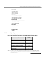
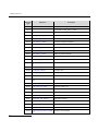
Tables
Table 1. SS7 Link Capacity of the Dialogic® DSI SS7MDL4 Network Interface Board............................................... 9
Table
Table
Table
Table
Table
Table
Table
2.
3.
4.
5.
6.
7.
8.
Dialogic® DSI SS7MD Software Licenses ................................................................................13
Link License Resource Requirements .....................................................................................13
Protocol Run Modes .............................................................................................................13
Link Type Available by Run Mode ..........................................................................................14
Message Summary ..............................................................................................................24
DSI SS7MD Board Software Module IDs .................................................................................27
Message Status Responses ...................................................................................................28
5
1 Introduction
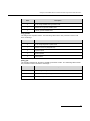
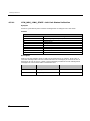
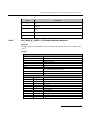
Revision History
Issue
Description
4
March 2012
Manual restructured for use in conjunction with Software Environment
Programmer’s Manual Issue 9 or later. All config.txt configuration commands
moved to that document.
3
July 2009
Description of thermal sensor operation added.
2
May 2009
Support for introduction of ATM termination mode and timestamping.
1
April 2009
Supports the first production release.
Note:
6
Date
The current version of this guide can be found at:
http://www.dialogic.com/support/helpweb/signaling
Dialogic® DSI SS7MD Network Interface Boards Programmer's Manual Issue 4
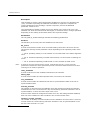
1
Introduction
Dialogic® DSI SS7MD Network Interface Boards are specialized T1/E1/J1 SS7 signaling
boards suitable for use in PCI Express form factor systems. The boards use the
common Dialogic® DSI software API to the application that enables applications to be
easily ported.
The boards provide a hardware platform to enable running Dialogic® DSI Protocol
Stacks for the realization of Signaling System Number 7 signaling nodes. In addition,
the DSI SS7MD Boards can be used to build high performance monitoring applications.
The boards can be used under the Linux, Solaris SPARC and Solaris x86 operating
systems.
This manual is the Programmer’s Manual for the Dialogic® DSI SS7MD range of
network interface boards. It is targeted for system developers who are integrating the
boards and who have chosen to develop applications that use the underlying DSI
Protocol Stack. The manual includes information on:
SS7MD board specification
SS7MD board-specific configuration
Operation of the SS7MD board with Dialogic® DSI Software Protocols
SS7MD board-specific message reference
The manual should be used in conjunction with the appropriate Installation Guide and
Regulatory Notice for the board. These and other supporting documentation, including
the Programmer’s Manuals for the individual protocol modules, are listed in Section 1.1
Related Information.
Note:
1.1
This document is specific to the Dialogic® DSI SS7MD board. Users of other Dialogic® DSI
board types should refer to the appropriate documentation for that board.
Related Information
Refer to the following for related information:
•
Dialogic® DSI SS7MDL440Q Network Interface Boards Installation Guide
•
Dialogic® DSI SS7MDL440Q Network Interface Boards Regulatory Notices
•
Dialogic® Distributed Signaling Interface Components - Software Environment
Programmer’s Manual
•
Dialogic® SS7 Protocols MTP3 Programmer’s Manual
•
Dialogic® SS7 Protocols ISUP Programmer's Manual
•
Dialogic® DSI Protocol Stacks - Host Licensing User Guide
•
Dialogic® DSI Protocol Stacks SNMP User Manual
Current software and documentation supporting Dialogic® DSI SS7MD Boards is
available at http://www.dialogic.com/support/helpweb/signaling.
7
2 Specification
2
Specification
This section provides information about:
2.1
•
Product Identifier
•
Hardware Specification
•
Operating System Support
•
Software Licenses
•
SNMP Support
•
Regulatory and Geographic Considerations
Product Identifier
The full designation of the Dialogic® DSI SS7MD Network Interface Board product is:
Dialogic® DSI SS7MDL4 Network Interface Board - Low Profile PCI Express Form Factor
Product
The product identifier is “SS7MDL440Q”
Within the remainder of the document the generic terms “DSI SS7MD” or “SS7MD” are
used.
A low profile PCI Express form factor with 4 T1/E1/J1 ports, supporting up to 124 SS7
links, up to 4 SS7 HSL links, up to 128 Q.SAAL links, or 4 ATM cell streams.
2.2
Hardware Specification
2.2.1
Host Interface
The DSI SS7MDL4 board has a x1 lane electrical, x4 lane physical PCI Express
connector and is a low profile PCI Express form factor, which can be installed in x4,
x8, or x16 lane PCI Express slots. The board is supplied with two End Brackets suitable
for low profile and full height installation.
Note:
2.2.2
The DSI SS7MDL4 board is a high performance densely packed low-profile PCIe board
supporting high message rates. In achieving this performance, the board may dissipate up
to 17W and this must be taken into consideration when selecting both the host chassis and
the PCI Express slot in which to install the board. Refer to Section 2.2.7, “Airflow
Requirements”.
Physical Interfaces
The DSI SS7MDL4 board supports four individually software configurable E1/T1/J1
digital trunk interfaces with the following properties:
• Standard
— Four interfaces each are software configurable as either T1, E1, or J1
— High impedance software selectable
8
Dialogic® DSI SS7MD Network Interface Boards Programmer's Manual Issue 4
• Pulse mask
— T1: ANSI T1.403
— E1: ITU-T G.703
— J1: TTC JT-G.703
• Data rate
— T1: 1544 kbits/s ± 50 ppm
— E1: 2048 kbits/s ± 50 ppm
— J1: 1544 kbits/s ± 50 ppm
• Frame format
— T1: F4, D3/D4, ESF, and F72/SLC96
— E1: E1 and E1-CRC4
— J1: J1 frame format
• Line codes
— T1: B8ZS and AMI
— E1: HDB3 and AMI
— J1: B8ZS and AMI
• Connector type
— RJ-48C
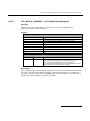
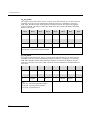
2.2.3
Capacity
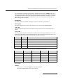
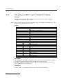
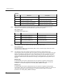
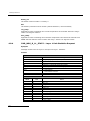
The SS7 link capacity of the DSI SS7MDL4 board is as follows:
®
Table 1. SS7 Link Capacity of the Dialogic DSI SS7MDL4 Network Interface Board
Link type
Q.703 LSL (64kbit/s)
124
Q.703 LSL (56kbit/s)
123
Q.703 LSL (48kbit/s)
123
Q.703 Annex A HSL Framed
4
Q.2140/Q.2110 Q.SAAL links (terminated)
128
AAL5 (including Q.SAAL) links (monitored)
128
ATM cell streams
Note:
Max. number of links
per board
4
In order to monitor both directions of a signaling link, the user must separately connect
each direction of the signaling link to the receive connection of two different LIUs on the
DSI SS7MDL4 board.
9
2 Specification
2.2.4
Protocol Resource Support
When terminating SS7 signaling, the DSI SS7MD board runs the SS7 Message Transfer
Part, Layer 2 (MTP2) on the board and works in conjunction with higher layer protocols
including MTP3, ISUP, SCCP, TCAP, MAP, INAP and IS41 running on the host. The
protocols are enabled by software licenses. See Section 2.4, “Software Licenses”.
The DSI SS7MDL4 board supports passive monitoring of HDLC format data links
including, for example, SS7, LAPB, LAPD, ISDN, and DPNSS. In this mode, the
received messages are directly reported to the application.
It is possible to use monitor and terminate protocol operation concurrently on the
same signaling board.
2.2.5
Visual Indicators
The DSI SS7MDL4 board includes the following visual indicators:
• T1/E1/J1 dual-color Green/Red status LEDs:
— Green indicates a valid link
— Red indicates a line alarm
Note:
2.2.6
Only the LEDs 0, 1, 2, and 3 are active (LEDs 4, 5, 6, and 7 are reserved for future use).
Power Requirements
Power requirements are described as follows:
• +12 VDC power
1.1 A typical, 1.4 A max.
• Power dissipation
17 W max.
2.2.7
Airflow Requirements
The board should be installed in host computers providing airflow of at least 300 linear
feet per minute (LFM), 1.5 m/s. This airflow should be evenly distributed across the
board. See Appendix B, “Thermal guidelines for selecting suitable servers for use with
a Dialogic® DSI SS7MDL4 Network Interface Board”.
10
Dialogic® DSI SS7MD Network Interface Boards Programmer's Manual Issue 4
2.2.8
Physical Specification
Form factor
Low-profile PCIe
Dimensions
Board
Length
167.65 mm (6.60 inches)
Height
68.90 mm (2.731 inches)
Packaged
Length
277 mm (10.9 inches)
Width
180 mm (7.08 inches)
Height
55 mm (2.16 inches)
Weight
2.2.9
Board
150 g
Packaged Board
345 g
Environmental Specification
Environmental specification is described as follows:
• Operating temperature range
+0°C to +55°C
• Storage temperature range
-20°C to +70°C
• Humidity
5% to 95% non-condensing
• Altitude
0 to 15,000 ft
• Vibration
0.1 g, 5 to 100 Hz
• Shock
Packaged equipment drop test 29.5 in (750 mm)
2.2.10
Safety, EMC and Telecommunications Specifications
Safety, EMC and telecommunications specification information is provided by the
following:
• Dialogic® DSI SS7MDL440Q Network Interface Board Regulatory Notices
Supplied with each product and provides a list of the specifications to which DSI
SS7MDL4 board conforms.
• International Declaration of Conformity
11
2 Specification
See http://www.dialogic.com/declarations.
• Country-Specific Approvals
See the Global Product Approvals list at http://www.dialogic.com/declarations.
Alternatively, contact your Dialogic technical sales representative for more information.
2.2.11
Reliability
Product reliability is described by:
• MTBF Predication
797,000 hours Telcordia SR-232, ground benign @ 40°C
• Warranty
See Dialogic® Telecom Products Warranty Information at
http://www.dialogic.com/warranties.
2.3
Operating System Support
The Dialogic® DSI SS7MD Network Interface Board can be used under the following
operating systems:
Linux
Solaris SPARC
Solaris x86
Users should download the appropriate Dialogic® DSI Development Package from the
web-site at http://www.dialogic.com/support/helpweb/signaling
2.4
Software Licenses
The DSI SS7MDL4 code file supports different MTP2 link densities on the board. These
are enabled using a Host Software License that is to be ordered at the same time as
the hardware. The Host Software License licenses a specific number of link resources
on the host that may be shared between boards in the same chassis.
For details on how to activate the host license please refer to Dialogic® DSI Protocol
Stacks - Host Licensing User Guide at
http://www.dialogic.com/support/helpweb/signaling.
A combination of link types (provided they are supported by the board’s run mode)
may be configured by the host (on any board) provided the required link resources are
available. A configured link’s resources are freed when either the link is unconfigured
or the board on which the link is currently active is reset.
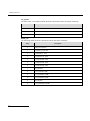
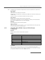
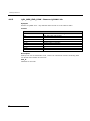
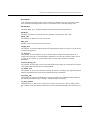
The following table shows the available licenses:
12
Dialogic® DSI SS7MD Network Interface Boards Programmer's Manual Issue 4
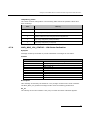
Table 2. Dialogic® DSI SS7MD Software Licenses
Software License
Code
Link Resources
SW LICENSE, 16 LSL
SS7SBMDM16
16
SW LICENSE, 32 LSL or 1 MTP or ATM HSL
SS7SBMDM32
32
SW LICENSE, 64 LSL, 2 MTP or ATM HSL
SS7SBMDM64
64
SW LICENSE, 128 LSL, 4 MTP or ATM HSL
SS7SBMDM128
128
SW LICENSE, 256 LSL, 8 MTP or ATM HSL
SS7SBMDM256
256
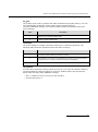
The number of link resources required for each link type is shown below:
Table 3. Link License Resource Requirements
Link Type
Resources Required
LSL (64Kb / 56Kb / 48Kb)
Note:
2.4.1
1
Monitored LSL
0.5
HSL (2Mb / 1.5Mb)
32
Monitored HSL
16
ATM (2Mb / 1.5Mb)
32
Monitored ATM
16
IMA bundles are licensed based on the number of ATM cell streams they contain.
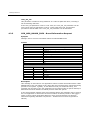
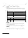
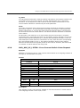
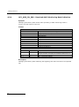
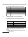
Run Modes
The run mode of a board determines the combination of protocols (LSL/HSL/ATM/IMA)
available to use. To change the run mode it is necessary to reset the board.
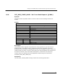
Table 4. Protocol Run Modes
Value
Run Mode
Protocols Selected to Run on the Board
34
LSL
MTP2 Low Speed Links
35
HSL
MTP2 High Speed Links and/or MTP2 Low Speed Links
36
ATM
ATM links and/or MTP2 High Speed Links and/or MTP2 Low Speed Links
37
IMA
Inverse Multiplexed ATM links
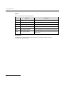
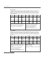
The following combinations of link types are available to the user:
13
2 Specification
Table 5. Link Type Available by Run Mode
Run Mode
LSL Links
HSL Links
LSL
Y
HSL
Y
Y
ATM
Y
Y
IMA
2.5
ATM Links
IMA Links
Y
Y
Y
SNMP Support
The Dialogic® Distributed Structured Management Information (DSMI) Simple Network
Management Protocol (SNMP) Agent provides SNMP monitoring functionality for the
Dialogic® DSI SS7 Development Package.
Dialogic® DSMI SNMP software supports SNMP V1, V2, and V3 reporting the state and
events for Dialogic® DSI SS7MD Network Interface Boards and Dialogic® DSI Protocol
Stacks through use of SNMP traps as well as queries from an SNMP manager.
The Dialogic® DSMI MIBs are distributed within the Dialogic® DSI SS7 Development
Package in the /opt/DSI sub-directory as a compressed ZIP file: dsi-mibs.zip.
For details of the DSMI SNMP MIBs supported, events, SNMP traps and configuration,
refer to the Dialogic® DSI Protocol Stacks SNMP User Manual.
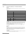
2.6
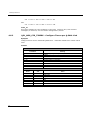
Regulatory and Geographic Considerations
Certain functions of Dialogic® DSI SS7MD Network Interface Board, although
implemented in hardware, have selectable options that are configured by the software.
A user or integrator must consider the requirements of the application when choosing
these settings, but must also consider any local regulatory requirements for the
intended deployment location to provide a compliant overall system. As an aid to this
process, the table below details some of the areas where the correct selection of
configuration options may be required.
Configuration Area
T1/E1 Ports
Links
14
Configuration Options
Interface type
liu_type parameter in LIU_CONFIG command
Pulse shape
liu_type parameter in LIU_CONFIG command
Line code
line_code parameter in LIU_CONFIG command
Frame format
frame_format parameter in LIU_CONFIG command
CRC/E-bit operation
CRC_mode parameter in LIU_CONFIG command
Clock priorities
flags parameter in SS7_BOARD command and
options parameter in LIU_CONFIG command
Link termination or monitoring
mode
MTP_LINK or MONITOR_LINK commands
Dialogic® DSI SS7MD Network Interface Boards Programmer's Manual Issue 4
3
SS7MD Board-Specific Configuration and
Operation
Before attempting software configuration, you should gain an understanding of the
flexibility of the protocol stack, the run-time options that exist and the mechanisms
that are used to select specific features. These are explained in the Dialogic®
Distributed Signaling Interface Components - Software Environment Programmer’s
Manual which also describes the basic principles of modules and message passing.
This section provides product-specific options relating to the following:
System configuration using SS7MD Board
Monitoring
ATM Monitoring
Switching Timeslots between LIUs
High Speed Link Operation
Operation of the Thermal Sensor
3.1
System configuration using SS7MD Board
The Dialogic® DSI MTP2 Layer protocol module runs on the board. The other SS7
protocol modules (MTP3, ISUP, SCCP, TCAP, MAP, INAP, and IS41) run on the host
machine.
Host protocol software is available for Linux, Solaris SPARC, and Solaris x86 operating
systems. For more information or to purchase, contact an authorized distributor or
your account manager.
The Dialogic® DSI SS7MD Network Interface Board may be configured for most
applications using the s7_mgt utility. The s7_mgt utility is the primary tool for
configuring a DSI software stack. It is a single-shot configuration utility that takes
configuration commands from a text file (config.txt).
Details on how to configure a system using s7_mgt are provided in the Dialogic®
Distributed Signaling Interface Components - Software Environment Programmer’s
Manual.
As an alternative to using s7_mgt, users can build their own configuration utilities
using messaged-based configuration. In this case users should refer to the definitions
of individual messages in Section 4, Message Reference on page 24.
The Code File contains the operating firmware for the board which is downloaded to
the board at run-time by the ssdm binary. The code file should be specified in the
SS7BOARD command in the config.txt file.
The following code files are available for the SS7MD board:
The ss7mcd.dc6 code file which should be used for SS7MD boards running the
LSL, HSL or ATM run modes.
The ss7.dc6 code file which should be used for SS7MD boards when timeslot
switching is necessary.
The ima.dc6 code file which should be used for SS7MD boards running the IMA
run mode.
15
3 SS7MD Board-Specific Configuration and Operation
Note:
The ss7.dc6 and ss7mcd code files are distributed as part of the Dialogic® DSI Development
Package. The ima.dc6 code file is available on request.
The code file requires a host license which enables the software to run on the board,
details on how to use a Host License are given in the Dialogic® Distributed Signaling
Interface Components Host Licensing User Guide.
3.2
Monitoring
The DSI SS7MD board can be used in conjunction with the SS7 Development Package
for the appropriate operating system (Linux, Solaris SPARC or Solaris x86) to realize a
high-performance protocol monitor with up to 4 boards, each monitoring a certain
number of links (see the table in Section 2.4.1, “Run Modes”).
In this mode the board is able to monitor many HDLC based signaling protocols
including SS7, LAPB, Q.921 (ISDN PRI) and DPNSS. The protocol should have a
minimum frame length (excluding flags) of 5 octets and a maximum of 278 octets, and
must use the CRC polynomial (x16 + x12 + x5 + 1). When operating in monitoring
mode, the 3rd and successive identical frames may be filtered.
It is possible to configure monitoring and terminated SS7 links on the same signaling
board.
For receive only operation, the board allows the T1/E1/J1 interfaces to be configured in
any of the following modes:
- Normal terminated impedance
- High impedance (not recommended for new designs)
- Protected Monitoring Point mode (preferred mode of operation for monitoring).
When using High Impedance mode care should be taken to avoid long cable runs as
this can result in poor signal quality due to signal reflections.
3.2.1
Configuration
The user needs to set up the configuration for the T1/E1/J1 interface and the operating
parameters for each link to be monitored. This can be achieved using the config.txt file
in conjunction with the s7_mgt configuration utility. Users wishing to use discrete
message-based configuration should to Section A.2, “Monitoring Configuration Using
Individual Messages”.
3.2.2
Runtime Operations
Once configured, whenever a frame is received, it is reported to the user’s application
as an API_MSG_RX_IND message.
During operation, the user may also read (and optionally reset) various statistics on a
per-link basis by sending a DVR_MSG_R_L1_STATS message.
16
Dialogic® DSI SS7MD Network Interface Boards Programmer's Manual Issue 4
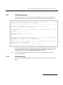
3.3
ATM Monitoring
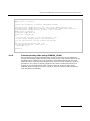
The system can also be used to monitor AAL5 traffic that is running over ATM links.
The following is an example config.txt configuration file to support AAL5 Monitoring:
********************************************************************************
* Example Protocol Configuration File (config.txt) for use with
* Dialogic(R) DSI SS7MD Network Interface Boards.
********************************************************************************
*
* SS7_BOARD
<board_id> <board_type> <flags> <code_file> <run_mode>
SS7_BOARD 0 SS7MD 0x0001 ./DC/ss7.dc6 ATM
*
* LIU_CONFIG <board_id> <liu_id> <liu_type> <line_code> <frame_format> <crc_mode>
[<build_out>]
LIU_CONFIG 0 0 6 1 1 1 0
*
* ATM_CONFIG <options> <num_streams>
ATM_CONFIG
0x0000 4
*
*
* ATM_STREAM <id> <board_id> <cellstream_id> <liu_id> <options> <ima_frame_len>
<max_frame_len> <def_vpi> <def_vci> <timeslot>
ATM_STREAM 3 0 1 0 0x01 0 280 12 10 0xfffefffe
*
* MONITOR_LINK <link_id> <board_id> <blink> <atm_stream> <VPI-VCI> <user_module>
<filter> <flags> <phys_mask> ATM
MONITOR_LINK 0 0 0 3 9-128 0x0d 0 0x0000 0x00 ATM
*
********************************************************************************
The underlying ATM system is configured using the ATM_CONFIG command. The links
to be used are then specified using the ATM_STREAM command and monitoring is
established for these links using the MONITOR_LINK command.
Note:
3.3.1
The use of these commands and others is explained in the DSI Software Environment
Programmer’s Manual.
IMA Monitoring
When configuring IMA Monitoring, the maximum limit is 31 monitoring links per IMA
bundle.
17
3 SS7MD Board-Specific Configuration and Operation
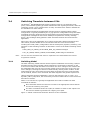
3.4
Switching Timeslots between LIUs
The Dialogic® DSI SS7MD Boards support multiple T1/E1/J1 Line Interface Units
(LIUs). The onboard signaling processor handles the SS7 signaling timeslots, while the
remaining circuits (voice or data bearer circuits) are switched to another onboard LIU
for distribution to other boards.
Communication between the application and the board is message-based. Initial
configuration is typically handled by the s7_mgt protocol configuration utility that takes
commands from the config.txt protocol configuration file and generates the necessary
configuration messages for the board. Subsequent operation is entirely message
driven, with messages being passed in both directions between the board and the
application.
One of the roles of the application is to control the dynamic switching between LIUs.
This section provides details of how to interface with the cross connect switch,
including the initial (static) configuration and the subsequent (dynamic) switching. The
operation of the switching interface is described in terms of the SCbus switching model
using:
• MVD_MSG_SC_DRIVE_LIU and MVD_MSG_SC_LISTEN messages
• LIU_SC_DRIVE, SCBUS_LISTEN, and STREAM_XCON config.txt commands.
Note:
3.4.1
The use of these commands and others is explained in the DSI Software Environment
Programmer’s Manual.
Switching Model
The basic switching model assumes that at system initialization all incoming T1/E1/J1
timeslots and all resource board output timeslots are connected to channels on the
cross connect switch and that these connections are never changed. This scheme has
the advantage that once the cross connect switch drivers have been set up, they are
never changed, reducing the chances of inadvertently causing switch conflict. It also
means that the user can predict the exact switch channels where any input timeslot
can be located, which in turn can assist with fault diagnosis and general system test.
Having completed system initialization, drives to the switch are set up. Then, on a
dynamic (call-by-call) basis, the connectivity must be modified when a new call arrives
and when it finishes.
When a new call arrives, typically the application will need to initiate two listen
commands as follows:
One command causes the resource to listen to the appropriate switch channel
to hear the incoming voice path.
The other command causes the T1/E1/J1 interface to listen to the output from
the resource board to generate the outgoing voice path.
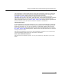
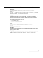
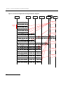
Figure 1. Switch Connections shows the function of the commands.
18
Dialogic® DSI SS7MD Network Interface Boards Programmer's Manual Issue 4
Figure 1. Switch Connections
3.4.2
Static Initialization
Static initialization is handled by the s7_mgt protocol configuration utility. For each
T1/E1/J1 Line Interface Unit (LIU), the user should include an LIU_SC_DRIVE
command in the config.txt protocol configuration file. The LIU_SC_DRIVE command has
several parameters. The board_id and liu_id parameters together uniquely identify the
affected LIU. The sc_channel parameter is the channel number of the first channel on
the switch that is to be used for timeslots from the specified LIU. The ts_mask
parameter is a mask identifying which timeslots on the T1/E1/J1 interface are carrying
voice circuits (as opposed to signaling) and therefore need to be connected to the
switch. The least significant bit of ts_mask should be 0 when driving from a T1/E1/J1
interface.
As an example, consider a two board system where the first board has four E1 ports
and the second board has four T1 ports (timeslots are numbered on a per board basis).
LIU_SC_DRIVE 0 0 0 0xfffefffe * 30 E1 voice ccts on ts 1..15 & 17..31
LIU_SC_DRIVE 0 1 30 0xfffefffe * 30 E1 voice ccts on ts 1..15 & 17..31
LIU_SC_DRIVE 0 2 60 0xfffefffe * 30 E1 voice ccts on ts 1..15 & 17..31
LIU_SC_DRIVE 0 3 90 0xfffefffe * 30 E1 voice ccts on ts 1..15 & 17..31
LIU_SC_DRIVE 1 0 23 0x00fffffe * 23 T1 voice ccts on timeslots 1..23
LIU_SC_DRIVE 1 1 46 0x00fffffe * 23 T1 voice ccts on timeslots 1..23
LIU_SC_DRIVE 1 2 69 0x00fffffe * 23 T1 voice ccts on timeslots 1..23
LIU_SC_DRIVE 1 3 72 0x00fffffe * 23 T1 voice ccts on timeslots 1..23
19
3 SS7MD Board-Specific Configuration and Operation
3.4.3
Dynamic Operation
The application controls dynamic changes to switching by sending the
MVD_MSG_SC_LISTEN message to the board. This message contains the liu_id (in the
range 0 to one less than the number of LIUs), the timeslot number on the T1/E1/J1
interface and the switch channel number (sc_channel) to which the timeslot should
listen. The message is directed to the correct board by calling the GCT_set_instance( )
function prior to calling the GCT_send( ) function.
When a new call arrives, the application will need to issue two listen commands
(although they will not necessarily both apply to the SS7 board). One connects the
voice circuit in the forward direction and the other connects voice circuit in the
backward direction. See Figure 1. Switch Connections.
3.4.4
Example Code for Building and Sending MVD_MSG_SC_LISTEN
Message
The following code demonstrates how to build and send a MVD_MSG_SC_LISTEN
message to the DSI SS7MD Board to listen to a switch timeslot.
/*
* Example function for building and sending an MVD_MSG_SC_LISTEN
* message to an SS7 signaling card.
*
* The only change that the user needs to make is to fill in the
* OUR_MOD_ID definition below so that it is equal to the module_id
* of the application module.
*/
#define OUR_MOD_ID (0xef)
#include "system.h" /* Definitions of u8, u16 etc */
#include "msg.h" /* Definitions of HDR, MSG etc */
#include "libc.h" /* Used only for memset prototype */
#include "sysgct.h" /* Prototypes for GCT_xxx */
#include "pack.h" /* Prototypes for rpackbytes */
#include "ss7_inc.h" /* Message & module definitions */
/*
* Macro to generate the value for use in the rsp_req field of the
* message header in order to request a confirmation message:
*/
#define RESPONSE(module) (((unsigned short) 1) << ((module) & 0x0f))
/*
* Function to drive an SCbus / CT Bus timeslot
* onto a timeslot on a PCM port:
*/
int listen_to_scbus(board_id, liu_id, timeslot, sc_channel)
int board_id; /* board_id (0, 1, 2 ...) */
int liu_id; /* PCM port id (0 .. one less than no. of LIUs) */
int timeslot; /* Timeslot on the PCM port (1 .. 31) */
int sc_channel; /* SCbus / CT Bus channel number */
{
MSG *m;
u8 *pptr;
/*
* Allocate a message (and fill in type, id, rsp_req & len):
*/
if ((m = getm(MVD_MSG_SC_LISTEN, 0, RESPONSE(OUR_MOD_ID), MVDML_SCLIS)) != 0)
{
20
Dialogic® DSI SS7MD Network Interface Boards Programmer's Manual Issue 4
pptr = get_param(m);
memset(pptr, 0, m->len);
/*
* Enter the parameters in machine independent format:
*/
rpackbytes(pptr, MVDMO_SCLIS_liu_id, (u32)liu_id, MVDMS_SCLIS_liu_id);
rpackbytes(pptr, MVDMO_SCLIS_timeslot, (u32)timeslot, MVDMS_SCLIS_timeslot);
rpackbytes(pptr, MVDMO_SCLIS_sc_channel, (u32)sc_channel,
MVDMS_SCLIS_sc_channel);
m->hdr.dst = MVD_TASK_ID;
m->hdr.src = OUR_MOD_ID;
/*
* Call GCT_set_instance to route the message to the
* correct board and GCT_send to send the message.
* If GCT_send returns non-zero release the message.
*/
GCT_set_instance(board_id, (HDR *)m);
if (GCT_send(m->hdr.dst, (HDR *)m) != 0)
relm((HDR *)m);
return(0);
}
3.4.5
Interconnecting LIUs using STREAM_XCON
Interconnection of two Line Interface Units (LIUs) on the board is also supported
through the STREAM_XCON command which controls the cross connect switch on the
signaling board, enabling the cross connection of timeslots between any two LIUs
within the board. This command simplifies the cross connection enabling a group of
timeslots on one LIU to be directly mapped to the same numbered timeslots on a
second LIU on the same board using a single command. A typical usage of the
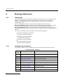
STREAM_XCON command is shown in Figure 2. Drop and Insert which implements
Drop and Insert functionality.
21
3 SS7MD Board-Specific Configuration and Operation
Figure 2. Drop and Insert
3.5
High Speed Link Operation
High Speed Link (HSL) operation is supported in the following mode:
• Structured mode, where the data stream is framed as for conventional SS7:
— For T1, 8 bits in each of 24 timeslots are available for signaling.
— For E1, timeslot 0 is used for framing and 31 timeslots are available for signaling.
The implementation supports the use of both 7-bit and 12-bit sequence numbers as a
run-time configuration option.
The DSI SS7MD Board will support up to 4 HSL links, dependent upon the licensing.
3.6
Operation of the Thermal Sensor
Thermal Protection
The Dialogic® DSI SS7MDL4 Network Interface Board is a high performance, densely
packed, low profile PCIe board supporting high message rates. In achieving this
performance, the board may dissipate up to 17W and this must be taken into
consideration when selecting both the host chassis and the PCI Express slot in which to
install the board, refer to 0, “Appendix B - Thermal guidelines for server selection”. In
order to guard against hardware failure due to inadequate cooling from the host
chassis, the board is provided with an on-board thermal sensor which, in the event
that the board gets too hot, will shutdown the board.
Safety Threshold
22
Dialogic® DSI SS7MD Network Interface Boards Programmer's Manual Issue 4
The temperature of the boards within a system are periodically measured, and should
the temperature of any board exceed a fixed safety threshold then a warning will be
provided to the host chassis that the threshold has been passed, a
MGT_MSG_EVENT_IND message with a status field of 0xc0 (Exceeded Thermal
Threshold) will be sent to SIU_MGT_TASK_ID (0xdf). If the board temperature remains
above this threshold limit for 30 minutes, but does not exceed the temperature at
which the board shuts down, the MGT_MSG_EVENT_IND message will be repeated and
this will continue every 30 minutes whilst the condition is maintained.
Thermal Shutdown
If the temperature of the board continues to rise, a second threshold will be passed at
which, to protect the hardware, the board will be shutdown. On reaching this Thermal
Shutdown threshold, the user will be notified via a SSD_MSG_STATE_IND message
with a status field of 0x62 (Board Failure) and a failure code parameter set to 0xd7. A
MGT_MSG_EVENT_IND message with a status field of 0xd7 (Shutdown due to Thermal
Issues) will also be sent.
Once these messages have been sent, all outstanding messages and all subsequently
received messages destined for the board will be discarded.
Reset after Thermal Shutdown
Once the board is shutdown, power can only be restored by a full power cycle of the
board.
23
4 Message Reference
4
4.1
Message Reference
Overview
This section describes the individual messages that may be sent to or received from a
Dialogic® DSI SS7MD Board. Some messages are sent by the user's application
software, while others are sent by utility programs such as the s7_mgt protocol
configuration utility.
Prior to sending any message to the board, the application should call the
GCT_set_instance( ) library function to select which board the message will be sent
to. After receiving a message from the board, the application should call the
GCT_get_instance( ) library function to determine which board the message came
from. These library functions are described in the Software Environment Programmer's
Manual.
The various messages used are grouped in the following categories:
General Configuration Messages
Hardware Control Messages
Signaling Interface Messages
ATM Interface Messages
Q.SAAL Interface Messages
Event Indication Messages
Status Request Messages
4.1.1
Message Type Summary
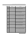
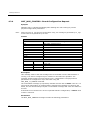
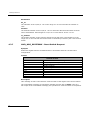
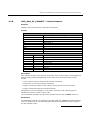
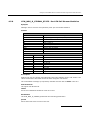
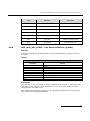
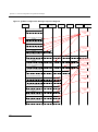
The following table lists, by message type, the messages described in this manual.
Table 6. Message Summary
Message
Type
24
Mnemonic
Description
0x0008
MGT_MSG_EVENT_IND
Error Indication
0x0201
MGT_MSG_SS7_STATE
Link State Indication
0x0202
MGT_MSG_SS7_EVENT
MTP2 Q.791 Event Indication
0x026a
ATM_MSG_STREAM_STATE
ATM Stream Status Indication
0x026b
ATM_MSG_LINK_STATE
AAL Link Status Indication
0x026c
MGT_MSG_QSL_EVENT
Q.SAAL "Q.791 style" Event Indication
0x06a0
SSD_MSG_STATE_IND
Board Status Indication
0x0e01
MVD_MSG_LIU_STATUS
LIU Status Indication
0x0f09
API_MSG_CNF_IND
Configuration Completion Status Indication
Dialogic® DSI SS7MD Network Interface Boards Programmer's Manual Issue 4
Message
Type
Mnemonic
Description
0x1213
Confirmation of SS7_MSG_TRACE_MASK
0x126d
Confirmation of ATM_MSG_TRACE_MASK
0x1e36
Confirmation of LIU_MSG_R_STATS
0x1e37
Confirmation of LIU_MSG_R_CONFIG
0x1e38
Confirmation of LIU_MSG_R_CONTROL
0x1e39
Confirmation of LIU_MSG_R_STATE
0x2214
Confirmation of SS7_MSG_R_STATS
0x2215
Confirmation of SS7_MSG_R_STATE
0x2263
Confirmation of ATM_MSG_R_STREAM_STATS
0x2266
Confirmation of ATM_MSG_R_AAL_LINK_STATS
0x2f0d
Confirmation of MGT_MSG_R_BRDINFO
0x3260
Confirmation of ATM_MSG_CONFIG
0x3261
Confirmation of ATM_MSG_CFG_STREAM
0x3262
Confirmation of ATM_MSG_END_STREAM
0x3264
Confirmation of ATM_MSG_AAL_CFG_MON_LINK
0x3265
Confirmation of ATM_MSG_AAL_END_LINK
0x3267
Confirmation of QSL_MSG_CFG_LINK
0x3268
Confirmation of QSL_MSG_CFG_TIMERS
0x3269
Confirmation of QSL_MSG_END_LINK
0x3680
Confirmation of SSD_MSG_RESET
0x3681
Confirmation of SSD_MSG_RST_BOARD
0x3689
Confirmation of SSD_MSG_BOARD_INFO
0x3e00
Confirmation of MVD_MSG_RESETSWX
0x3e17
Confirmation of MVD_MSG_SC_LISTEN
0x3e19
Confirmation of MVD_MSG_SC_MULTI_CONNECT
0x3e1f
Confirmation of MVD_MSG_SC_CONNECT
0x3e34
Confirmation of LIU_MSG_CONFIG
0x3e35
Confirmation of LIU_MSG_CONTROL
0x3f10
Confirmation of MGT_MSG_CONFIG0
25
4 Message Reference
Message
Type
26
Mnemonic
Description
0x3f17
Confirmation of MGT_MSG_L1_CONFIG
0x3f18
Confirmation of MGT_MSG_L1_END
0x5213
SS7_MSG_TRACE_MASK
Set Trace Mask Request
0x526d
ATM_MSG_TRACE_MASK
Set ATM Trace Mask Request
0x5e36
LIU_MSG_R_STATS
LIU Read Statistics Request
0x5e37
LIU_MSG_R_CONFIG
LIU Read Configuration Request
0x5e38
LIU_MSG_R_CONTROL
LIU Read Control Request
0x5e39
LIU_MSG_R_STATE
LIU Read State Request
0x6136
DVR_MSG_R_L1_STATS
Link Statistics Request
0x6214
SS7_MSG_R_STATS
Read Link Statistics Request
0x6215
SS7_MSG_R_STATE
Read Link State Request
0x6263
ATM_MSG_R_STREAM_STATS
Per ATM Cell Stream Statistics
0x6266
ATM_MSG_R_AAL_LINK_STAT
S
Per Monitored Link Statistics
0x6f0d
MGT_MSG_R_BRDINFO
Read Board Info Request
0x7260
ATM_MSG_CONFIG
Configure ATM
0x7261
ATM_MSG_CFG_STREAM
ATM Cell Stream Configuration
0x7262
ATM_MSG_END_STREAM
Remove ATM Cell Stream Configuration
0x7264
ATM_MSG_AAL_CFG_MON_LI
NK
Configure AAL Monitor Link
0x7265
ATM_MSG_AAL_END_LINK
Remove AAL Link
0x7267
QSL_MSG_CFG_LINK
Configure Q.SAAL Link
0x7268
QSL_MSG_CFG_TIMERS
Configure Timers per Q.SAAL Link
0x7269
QSL_MSG_END_LINK
Remove Q.SAAL Link
0x7680
SSD_MSG_RESET
SSD Reset Request
0x7681
SSD_MSG_RST_BOARD
Board Reset Request
0x7689
SSD_MSG_BOARD_INFO
Board Information Request
0x7e00
MVD_MSG_RESETSWX
Reset Switch Request
0x7e17
MVD_MSG_SC_LISTEN
Cross Connect Switch Listen Request
0x7e19
MVD_MSG_SC_MULTI_CONNE
CT
Multiple Connect Request
Dialogic® DSI SS7MD Network Interface Boards Programmer's Manual Issue 4
Message
Type
4.1.2
Mnemonic
Description
0x7e1f
MVD_MSG_SC_CONNECT
Connect Request
0x7e34
LIU_MSG_CONFIG
LIU Configuration Request
0x7e35
LIU_MSG_CONTROL
LIU Control Request
0x7f10
MGT_MSG_CONFIG0
Board Configuration Request
0x7f17
MGT_MSG_L1_CONFIG
Layer 1 Configuration Request
0x7f18
MGT_MSG_L1_END
Layer 1 Configuration End
0x8f01
API_MSG_RX_IND (LSL/HSL)
API_MSG_RX_IND (ATM)
Received Data Indication
0x8f06
API_MSG_RX_ERR
Received AAL5 Monitoring Error
0xcf00
API_MSG_TX_REQ
MTP2 Transmission Request
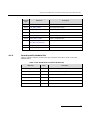
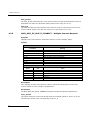
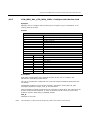
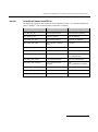
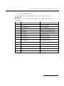
Board-specific Module IDs
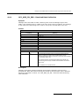
Table 7 lists the software modules IDs (by mnemonic and value) used on the DSI
SS7MD Board.
Table 7. DSI SS7MD Board Software Module IDs
Mnemonic
Value
Description
MGMT_TASK_ID
0x8e
SS7MD Board Management Module
MVD_TASK_ID
0x10
SS7MD LIU and Switch Management Module
SS7_TASK_ID
0x71
MTP2 Module
DVR_ALT_TASK_ID
0x61
Signaling Driver Module
ATM_TASK_ID
0x31
ATM Module
QSL_TASK_ID
0x41
Q.SAAL Module
27
4 Message Reference
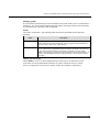
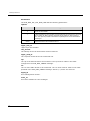
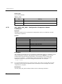
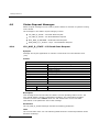
4.1.3
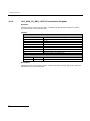
Message Status Summary
The following table shows the valid responses when a response request (rsp_req) is
requested in a message.
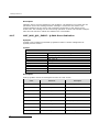
Table 8. Message Status Responses
Value
28
Mnemonic
Description
0x00
SDE_MSG_OK
Success
0x01
SDE_BAD_ID
Inappropriate or invalid id in request message
0x02
SDE_BAD_STATE
Message received in wrong state
0x03
SDE_BAD_SIG
Bad signal received
0x04
SDE_UNEX_SIG
Unexpected signal received
0x05
SDE_BAD_MSG
Unsupported message received
0x06
SDE_BAD_PARAM
Invalid parameters contained in message
0x07
SDE_NO_RESOURCES
Insufficient internal message resources
0x08
SDE_INVALID_NC
Invalid Network Context
0x09
SDE_INVALID_VERSION
Message version is invalid
0x0e
SDE_LICENCE_ERR
Failure due to a licensing restriction
0x0f
SDE_INTERNAL_ERR
Failure due to an internal error
Dialogic® DSI SS7MD Network Interface Boards Programmer's Manual Issue 4
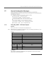
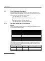
4.2
General Configuration Messages
General configuration messages are typically issued by the s7_mgt protocol
configuration utility, in which case they need not, and should not, be generated by any
user application software.
The messages in the general configuration category include:
SSD_MSG_RESET - SSD Reset Request
SSD_MSG_RST_BOARD - Board Reset Request
SSD_MSG_BOARD_INFO - Board Information Request
MGT_MSG_CONFIG0 - Board Configuration Request
MGT_MSG_L1_CONFIG - Layer 1 Configuration Request
MGT_MSG_L1_END - Layer 1 Configuration End
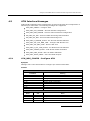
4.2.1
SSD_MSG_RESET - SSD Reset Request
Synopsis
Sets up ssd module run-time options at initialization time.
Note:
When using the s7_mgt protocol configuration utility, this message is generated by s7_mgt
and should not be generated by the user.
Format
MESSAGE HEADER
Field Name
Meaning
type
id
src
dst
rsp_req
hclass
status
err_info
len
SSD_MSG_RESET (0x7680)
0
Sending module ID
SSD_module_ID
Used to request a confirmation.
0
0
0
24
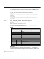
PARAMETER AREA
Offset
0
3
4
22
Size
3
1
18
2
Name
Reserved. Set to 0.
mgmt_id
Reserved. Set to 0.
num_boards
Description
This message is used during initialization by the application to reset the ssd module
and set up its run-time parameters.
29
4 Message Reference
The confirmation message (if requested) indicates success with a status value of 0.
Parameters
The SSD_MSG_RESET message includes the following parameters:
mgmt_id
The module ID of the management module to which SSD should send board status
indications.
num_boards
The maximum number of boards that ssd is required to manage. This should not
exceed eight.
4.2.2
SSD_MSG_RST_BOARD - Board Reset Request
Synopsis
Reset a single board and download a code file.
Note:
When using the s7_mgt protocol configuration utility, this message is generated by
s7_mgt and should not be generated by the user.
Format
MESSAGE HEADER
Field Name
Meaning
type
id
src
dst
rsp_req
hclass
status
err_info
len
SSD_MSG_RST_BOARD (0x7681)
board_id
Sending module ID
SSD_module_ID
Used to request a confirmation.
0
0
0
78
PARAMETER AREA
Offset
0
2
6
24
26
28
Size
2
4
18
2
2
50
Name
board_type
Reserved. Must be set to 0.
code_file
run_mode
options
code_file_ext
Description
This message is used by the application during initialization (or reconfiguration) to
reset a board and download the code file that contains the operating software for the
board. The download operation is supervised by the device driver that reads the binary
format code file and transfers it to the board.
30
Dialogic® DSI SS7MD Network Interface Boards Programmer's Manual Issue 4
The confirmation message (if requested) indicates success with a status value of 0.
This implies that the reset operation has commenced, but does not imply completion.
The application should then wait until a Board Status Indication message is received
that indicates either successful completion of the reset and download operation or
failure during the procedure.
Parameters
The SSD_MSG_RST_BOARD message includes the following parameters:
board_type
The type of board to be reset. This must be set to 16 for DSI SS7MD Boards.
code_file
Null terminated string giving the filename of the code file to be downloaded to the
board.
run_mode
The run_mode parameter determines which protocols will be permitted to run on the
board. Several modes permit multiple types of link to be used at the same time. The
following table shows the permitted values and their meaning:
Value
Run Mode
Protocols Selected to Run on the Board
34
LSL
MTP2 Low Speed Links
35
HSL
MTP2 High Speed Links and/or MTP2 Low Speed Links
36
ATM
ATM links and/or MTP2 High Speed Links and/or MTP2 Low Speed Links
37
IMA
Inverse Multiplexed ATM links
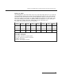
The following combinations of link types are available to the user:
Run Mode
LSL Links
HSL Links
LSL
Y
HSL
Y
Y
ATM
Y
Y
IMA
ATM Links
IMA Links
Y
Y
Y
The number of links that can be run on a board is controlled by the host-based runtime license.
options
-
Bit 0 set to 1 to enable SNMP for Board/PCM status
-
Other bits reserved for future use, set to 0.
31
4 Message Reference
code_file_ext
This parameter contains a string definition of a code file path and name, including a
null terminating character.
If the code_file parameter is set to a null value, the code_file_ext parameter will be
used. If the code_file parameter is set to a value other than null, this will take
precedence and the data in the code_file_ext parameter will be discarded.
4.2.3
SSD_MSG_BOARD_INFO - Board Information Request
Synopsis
Message used to retrieve information about the DSI SS7MD Board.
Format
MESSAGE HEADER
Field Name
Meaning
type
id
src
dst
rsp_req
hclass
status
err_info
len
SSD_MSG_BOARD_INFO (0x7689)
board_id
Sending module ID
SSD_module_ID
Used to request a confirmation.
0
0
0
38
PARAMETER AREA
Offset
0
4
6
16
36
37
Size
4
2
10
20
1
1
Name
ssdmode
btype
Reserved. Must be set to 0.
sernum
cur_temp
max_temp
Description
This message is used when a user application wants to obtain information about a DSI
SS7MD Board. This can happen at any time after the board has been reported as being
present in the system. Typically, in PCI address mode (see ssdmode below), this
message may be sent by the user application to the ssdm module at system startup to
determine the serial numbers of boards present within the system.
In the Serial number address mode (see ssdmode below) this message may be sent by
the user application to determine the serial numbers of boards present in the system
either via their logical geographic address or their physical address (see Dialogic®
Distributed Signaling Interface Components - Software Environment Programmer’s
Manual).
32
Dialogic® DSI SS7MD Network Interface Boards Programmer's Manual Issue 4
Parameters
The SSD_MSG_BOARD_INFO message includes the following parameters:
board_id
The board_id should be set to the logical board number or alternatively, if geographic
addressing is enabled, to the board’s physical address.
ssdmode
Returns the geographic address mode in which the ssdm module is running. This was
specified at system start-up in the system.txt file, for details refer to Dialogic®
Distributed Signaling Interface Components - Software Environment Programmer’s
Manual .
The geographic address modes values are:
— 1: PCI address mode
— 2: Serial number address mode
btype
The board type. For DSI SS7MD Boards, this parameter is set to 16.
sernum
The serial number of the board.
cur_temp
Signed 8-bit value containing the current temperature of the board within the range 128 to 127 degrees Celsius.
max_temp
Signed 8-bit value containing the maximum temperature the board has reached since
SSDM was last started. Value is within the range -128 to 127 degrees Celsius.
33
4 Message Reference
4.2.4
MGT_MSG_CONFIG0 - Board Configuration Request
Synopsis
Message sent to a board immediately after starting the code running to provide
physical configuration parameters.
Note:
When using the s7_mgt protocol configuration utility, this message is generated by s7_mgt
and should not be generated by the user.
Format
MESSAGE HEADER
Field Name
Meaning
type
id
src
dst
rsp_req
hclass
status
err_info
len
MGT_MSG_CONFIG0 (0x7f10)
0
Sending module ID
MGMT_module_ID
Used to request a confirmation.
0
0
0
68
PARAMETER AREA
Offset
0
2
4
6
Size
2
2
2
62
Name
config_type
flags
l1_flags
Reserved. Must be set to 0.
Description
This message must be the first message sent to the board once the SS7 software is
running. It is used to configure layer1 modules on the board for operation. The
message contains flags to permit various level 1 configurations. The physical link
parameters are configured on a per link basis using the
MGT_MSG_L1_CONFIG command.
The confirmation message (if requested) indicates success with a status value of 0. To
ensure that configuration is complete before subsequent messages are issued to the
board, the user should always request a confirmation message and check the status for
success.
If the board is not licensed to run the requested software configuration, a status value
of 0xfe is returned.
Parameters
The MGT_MSG_CONFIG0 message includes the following parameters:
34
Dialogic® DSI SS7MD Network Interface Boards Programmer's Manual Issue 4
config_type
Set to 3 when using a DSI SS7MD Board. A separate link layer configuration message
should be sent for each link using the MGT_MSG_L1_CONFIG message.
flags
Global flags with the following bit significance:
— Bit 15 is set to 1 for diagnostics purposes to cause the results of board configuration
to be passed to the host. When set, all confirmation messages generated internally on
the board during the configuration sequence are sent to the 0xdf module ID on the
host.
— All other bits are reserved for future use and should be set to 0.
l1_flags
Level 1 flags with the following bit significance:
— Bit 0 controls the layer 1 clock reference source. If set to 0, the clock is recovered
from the onboard oscillator. If set to 1, the clock is recovered from one of the line
interfaces. Line interfaces can be individually configured with the LIU_MSG_CONFIG
message to explicitly be excluded from recovering the clock from the interface.
— All other bits are reserved and should be set to 0.
35
4 Message Reference
4.2.5
MGT_MSG_L1_CONFIG - Layer 1 Configuration Request
Synopsis
Message sent to a board after successful processing of the MGT_MSG_CONFIG0
message to configure the layer 1 links.
Note:
When using the s7_mgt protocol configuration utility, this message is generated by s7_mgt
and should not be generated by the user.
Format
MESSAGE HEADER
Field Name
Meaning
type
id
src
dst
rsp_req
hclass
status
err_info
len
MGT_MSG_L1_CONFIG (0x7f17)
0
Sending module's module ID
MGMT_module_ID
Used to request a confirmation.
0
0
0
40
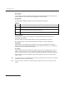
PARAMETER AREA
Offset
0
2
4
6
8
12
14
16
20
24
28
Size
2
2
2
2
4
2
2
4
4
4
12
Name
Reserved. Set to 0.
l1_resource_id
data_rate
link_source
Reserved. Set to 0.
link_stream
link_timeslot
Reserved. Set to 0.
options
timeslot_mask
Reserved. Set to 0.
Description
This message is used after successful processing of the MGT_MSG_CONFIG0 message
to configure physical signaling links. It should only be sent after the
MGT_MSG_CONFIG0 message has been sent. The message should be sent once for
each signaling link to be configured.
Parameters
The MGT_MSG_L1_CONFIG message includes the following parameters:
36
Dialogic® DSI SS7MD Network Interface Boards Programmer's Manual Issue 4
l1_resource_id
The logical identity of the link set, in the range 0 to one less than the number of link
sets supported, The linkset_id is used in other commands for reference
data_rate
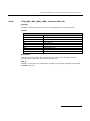
Used for setting the link operation. The following table shows the permitted values and
their meaning.
Value
Data Rate
0
64 kbits/s
1
56 kbits/s
2
48 kbits/s
link_source
Configure the signaling source.
Set to 0 for DSI SS7MD Board.
link_stream
Signaling stream. This parameter is the physical identity of the T1/E1/J1 line interface
containing the signaling link. The value range is 0 to one less than the number of LIUs.
link_timeslot
Signaling timeslot. This field is used to configure conventional SS7 links. The value
ranges for link_timeslot are 1 to 24 for a T1/J1 interface and 1 to 31 for an E1
interface.
options
A 32-bit value containing run-time options as follows:
— Bit 0 - Set to 1 to disable automatic FISU generation. This is normally required for
Japanese MTP operation only.
— Bit 1 - Set to 1 to enable onboard time stamping on monitored links. Setting this
bit changes the MSG type of the monitor message from API_MSG_RX_IND to
API_MSG_RX_INDT. This option is provided for backwards compatibility only.
— Bit 4 – This bit is used to select the size of the sequence number field. This is
necessary in addition to appropriate configuration of the MTP2 layer. The bit is only
applicable for HSL operation and should otherwise be set to zero. For HSL operation
the bit should be set to 0 for 7-bit sequence numbers or set to 1 for 12-bit sequence
numbers.
— Bit 6 – This bit is used to configure the layer 1 functionality to select between LSL
and HSL operation to ensure the appropriate error rate monitoring mechanism is
selected. This is necessary in addition to appropriate configuration of the MTP2 layer.
The value should be set to 0 for LSL operation and 1 for HSL operation.
— All Other Bits - Must be set to 0.
37
4 Message Reference
timeslot_mask
Signaling timeslot mask. This field is used to configure HSL links. Bits 0 to 31 of the
mask correspond to timeslots 0 to 31 of the signaling stream identified by the
link_stream parameter. The recommended bits masks values are:
Value
4.2.6
Description
0xfffffffe
structured E1 HSL, 31 slots (1 to 31)
0x01fffffe
structured T1 HSL, 24 slots (1 to 24)
0xfffefffe
structured E1 HSL, 30 slots (1 to 15,17 to 31)
MGT_MSG_L1_END - Layer 1 Configuration End
Synopsis
Message sent to a board to remove an existing layer 1 link that was previously
configured by sending an MGT_MSG_L1_CONFIG message.
Format
MESSAGE HEADER
Field Name
Meaning
type
id
src
dst
rsp_req
hclass
status
err_info
len
MGT_MSG_L1_END (0x7f18)
0
Sending module's module ID
MGMT_module_ID
Used to request a confirmation.
0
0
0
4
PARAMETER AREA
Offset
0
2
Size
2
2
Name
Reserved. Must be set to 0.
l1_resource_id
Parameters
The MGT_MSG_L1_END message includes the following parameters:
l1_resource_id
Layer 1 (logical) resource identifier.
38
Dialogic® DSI SS7MD Network Interface Boards Programmer's Manual Issue 4
4.3
Hardware Control Messages
Hardware control messages are used to control various hardware devices on the
board, including the T1/E1/J1 Line Interface Units (LIUs), the digital cross connect
switches and the clocking mode for the board.
In a static configuration, these hardware blocks can be set up using the s7_mgt protocol
configuration utility along with the appropriate commands in the config.txt protocol
configuration file.
If dynamic control of the hardware is required (or the user has elected not to use
s7_mgt), the user application must build and send at least some of the hardware
control messages.
The messages in the hardware control category include:
LIU_MSG_CONFIG - LIU Configuration Request
LIU_MSG_CONTROL - LIU Control Request
LIU_MSG_R_CONFIG - LIU Read Configuration Request
LIU_MSG_R_CONTROL - LIU Read Control Request
MVD_MSG_SC_DRIVE_LIU - LIU Switch Initialization
MVD_MSG_SC_LISTEN - Cross Connect Switch Listen Request
MVD_MSG_RESETSWX - Reset Switch Request
MVD_MSG_SC_CONNECT - Connect Request
MVD_MSG_SC_MULTI_CONNECT - Multiple Connect Request
39
4 Message Reference
4.3.1
LIU_MSG_CONFIG - LIU Configuration Request
Synopsis
Message sent by the application to establish the operating mode for a Line Interface
Unit (LIU).
Note:
When using the s7_mgt protocol configuration utility, this message is generated by s7_mgt
as a result of the LIU_CONFIG command. It therefore need not be generated by the user.
Format
MESSAGE HEADER
Field Name
Meaning
type
id
src
dst
rsp_req
hclass
status
err_info
len
LIU_MSG_CONFIG (0x7e34)
liu_id (in the range 0 to one less than the number of LIUs)
Sending module ID
MVD_module_ID
Used to request a confirmation.
0
0
0
40
PARAMETER AREA
Offset
0
1
2
3
4
5
11
12
18
19
21
Size
1
1
1
1
1
6
1
6
1
2
19
Name
liu_type
line_code
frame_format
crc_mode
build_out
Reserved. Must be set to 0.
ais_gen
Reserved. Must be set to 0.
sensitivity
clk_options
Reserved. Must be set to 0.
Description
This message is sent to the board to configure the operating mode of a Line Interface
Unit (LIU). All configuration parameters must be supplied in the message, that is, it is
not possible to modify individual operating parameters in isolation. On receipt of the
message, the board first verifies that the fitted hardware options support the
requested operating mode and then initializes (or reinitializes) the LIU.
The confirmation message (if requested) indicates success with a status value of 0.
40
Dialogic® DSI SS7MD Network Interface Boards Programmer's Manual Issue 4
Parameters
A description of the permitted parameter values are given below. When the board is
initially configured, the LIUs are initialized to a disabled condition. The message
includes the following parameters:
liu_type
The physical interface type according to the following table. The preferred method for
configuring an E1 interface is to set a value of 5.
Value
Description
1
Disabled (used to deactivate a LIU). In this mode, the LIU does not produce an output
signal.
3
E1 120 ohm balanced interface
4
T1 (including J1)
5
E1 120 ohm balanced interface
line_code
The line coding technique. The following table shows the permitted values and their
meanings.
Value
Description
1
HDB3 (E1 only)
2
AMI
4
B8ZS (T1/J1)
frame_format
The frame format. The following table shows the permitted values and their meanings.
Value
Description
1
E1 double frame (E1 only)
2
E1 CRC4 multiframe (E1 only)
3
F4 4-frame multiframe (T1 only)
4
D3/D4 (Yellow alarm = bit 2 in each channel (T1 only)
7
ESF (Yellow alarm in data link channel) (T1 only)
8
F72/SLC96 (72-frame multiframe) (T1 only)
9
J1 frame format (liu_type must be 4 [T1])
41
4 Message Reference
crc_mode
The CRC mode. The following table shows the permitted values and their meanings.
Value
Description
1
CRC generation disabled
2
CRC4 enabled (frame_format must be set to 2)
4
CRC6 enabled (frame_format must be set to 7)
build_out
The following table shows the permitted values and their meanings.
Value
42
Description
0
Setting for E1 devices
1
T1 default (T1 short haul)
2
T1 short haul 0 - 133 ft
3
T1 short haul 133 - 266 ft
4
T1 short haul 266 - 399 ft
5
T1 short haul 399 - 533 ft
6
T1 short haul 533 - 655 ft
7
Not supported.
8
T1 long haul LB0 (-0dB)
9
T1 long haul LB0 (-7.5dB)
10
T1 long haul LB0 (-15dB)
11
Not supported.
12
T1 long haul LBO (-22.5dB)
Dialogic® DSI SS7MD Network Interface Boards Programmer's Manual Issue 4
ais_gen
The (initial) mode used to generate the Alarm Indication Signal (Blue alarm). The user
may subsequently modify the setting of the outgoing signal using the
LIU_MSG_CONTROL message. The following table shows the permitted values and
their meanings.
Value
Description
1
Disabled; do not generate AIS/Blue alarm
2
Enabled; generate AIS/Blue alarm
sensitivity
The mode settings to configure interface sensitivity for monitoring purposes. The
following table shows the permitted values and their meanings.
Value
Description
1
Terminated; normal impedance presented on the line
2
High Impedance; set the LIU to high impedance for monitoring (not recommended for
new deployments, this mode is provided for backwards compatibility).
4
PMP mode; set the LIU sensitivity to operate with a Protected Monitoring Point.
clk_options
A 16-bit value containing clocking options for the LIU. This value provides the ability to
override default LIU clocking options for each LIU. Default options are specified per
board within the MGT_MSG_CONFIG0 message.
— Bit 0 - Disable LIU clock recovery for this interface.
— All other bits set to 0.
43
4 Message Reference
4.3.2
LIU_MSG_CONTROL - LIU Control Request
Synopsis
Message sent by the application to dynamically control operation for a Line Interface
Unit (LIU). Allows setting of outgoing alarms and diagnostic loopbacks.
Format
MESSAGE HEADER
Field Name
Meaning
type
id
src
dst
rsp_req
hclass
status
err_info
len
LIU_MSG_CONTROL (0x7e35)
liu_id (in the range 0 to one less than the number of LIUs)
Sending module ID
MVD_module_ID
Used to request a confirmation.
0
0
0
16
PARAMETER AREA
Offset
0
1
2
3
4
5
Size
1
1
1
1
1
11
Name
ais_gen
Reserved for future use, must be set to 0.
loop_mode
Reserved for future use, must be set to 0.
prbs_gen
Reserved for future use, must be set to 0.
Description
This message is sent to the board to perform dynamic changes to the operation of the
Line Interface Unit (LIU). It allows the user to control the generation of AIS (Blue
alarm) and to activate various diagnostic loopback modes. It also allows the
configuration of PRBS test sequences.
The confirmation message (if requested) indicates success with a status value of 0.
Parameters
The LIU_MSG_CONTROL message includes the following parameters:
ais_gen
The mode used to generate the Alarm Indication Signal (Blue alarm). The following
table shows the permitted values and their meanings.
44
Dialogic® DSI SS7MD Network Interface Boards Programmer's Manual Issue 4
Value
Description
0
Do not change AIS/Blue alarm generation mode
1
Disabled; do not generate AIS/Blue alarm
2
Enabled; generate AIS/Blue alarm
loop_mode
The diagnostic loopback mode. The following table shows the permitted values and
their meanings.
Value
Description
0
Do not change diagnostic loopback mode
1
Disabled - remove any diagnostic loop
2
Payload loopback
3
Remote loopback
4
Local loopback
prbs_gen
The Pseudo Random Bit Sequence (PRBS) generation mode. The following table shows
the permitted values and their meanings.
Value
Description
0
Do not change PRBS generation mode
1
Disabled - remove any PRBS generation
3
Generate PRBS pattern QRSS 20
45
4 Message Reference
4.3.3
LIU_MSG_R_CONFIG - LIU Read Configuration Request
Synopsis
Message sent by the application to read back the current Line Interface Unit (LIU)
configuration from the board.
Format
MESSAGE HEADER
Field Name
Meaning
type
id
src
dst
rsp_req
hclass
status
err_info
len
LIU_MSG_R_CONFIG (0x5e37)
liu_id (in the range 0 to one less than the number of LIUs)
Sending module ID
MVD_module_ID
Used to request a confirmation.
0
0
0
40
PARAMETER AREA
Offset
0
Size
40
Name
Parameter area formatted in the same manner as the
LIU_MSG_CONFIG message. All fields should be set to 0.
The confirmation message contains the board configuration details.
The user should set the fields to 0 and the module writes the current
configuration parameters in the confirmation message.
Description
This message is sent to the board to read back the current operating configuration of
the LIU. The user should always request a confirmation message. The confirmation
message indicates success with a status value of 0 and contains the current
configuration parameters in the parameter area of the message.
46
Dialogic® DSI SS7MD Network Interface Boards Programmer's Manual Issue 4
4.3.4
LIU_MSG_R_CONTROL - LIU Read Control Request
Synopsis
Message sent by the application to read back the current Line Interface Unit
(LIU) control options from the board.
Format
MESSAGE HEADER
Field Name
Meaning
type
id
src
dst
rsp_req
hclass
status
err_info
len
LIU_MSG_R_CONTROL (0x5e38)
liu_id (in the range 0 to one less than the number of LIUs)
Sending module ID
MVD_module_ID
Used to request a confirmation.
0
0
0
16
PARAMETER AREA
Offset
0
Size
16
Name
Parameter area formatted in the same manner as the
LIU_MSG_CONTROL message. All fields should be set to 0.
The confirmation message contains LIU control options.
The user should set the fields to 0 and the module writes the current
control parameters in the confirmation message.
Description
This message is sent to the board to read back the current control parameters selected
for a LIU. The user should always request a confirmation message. The confirmation
message indicates success when the status value of 0 and contains the current control
parameters in the parameter area of the message.
47
4 Message Reference
4.3.5
MVD_MSG_SC_DRIVE_LIU - LIU Switch Initialization
Synopsis
Sets up a static switch path through the board between a CPU local bus timeslot and a
switching channel.
Format
MESSAGE HEADER
Field Name
Meaning
type
id
src
dst
rsp_req
hclass
status
err_info
len
MVD_MSG_SC_DRIVE_LIU (0x7e18)
0
Sending module's Id
MVD_TASK_ID
Used to request a confirmation
0
0
0
10
PARAMETER AREA
Offset
0
2
4
8
Size
2
2
4
2
Name
liu_id
sc_channel
ts_mask
mode
Description
This message is sent to connect selected CPU local bus timeslots from an T1/E1/J1 Line
Interface Unit (LIU) or CPU stream to a block of cross connect switch channels. Upon
receiving this message, switch channels are prepared to make a cross connect switch
connection to outgoing CPU local bus timeslots upon receiving subsequent
MVD_MSG_SC_LISTEN messages.
The confirmation message (if requested) indicates success with a status value of 0.
Parameters
liu_id
The identifier of the T1/E1/J1 LIU in the range 0 to one less than the number of LIUs.
This parameter can be set to a value of a CPU local bus streams in the range of 0x90
upwards, where the number of CPU local bus streams equals one less than the number
of LIUs. The timeslot value 0 to 31 in the ts_mask parameter correspond to the
signalling processors signaling links.
sc_channel
The logical value of the first switch channel to be used. This should be in the range of 0
to the total number of channels available on the board.
48
Dialogic® DSI SS7MD Network Interface Boards Programmer's Manual Issue 4
ts_mask
A 32-bit timeslot mask where each bit position represents a local stream timeslot to be
connected to the cross connect switch. The least significant bit (bit 0) represents
timeslot 0. The arrangement of CPU local bus stream timeslot connections to cross
connect switch channels is controlled by the mode parameter.
mode
The mode of operation that controls how the switch channels are allocated. Typically,
when mode is set to 1, the first timeslot connected to the switch is connected to the
timeslot indicated by sc_channel and each subsequent timeslot that is connected will
be connected to the next switch channel. This allows maximum utilization of channels
on the switch.
An alternative, with mode set to 2, which should only be used if there is a specific
requirement for it, associates (but does not necessarily connect) timeslot 0 on the LIU
with the switch timeslot specified by sc_channel and subsequent timeslots on the LIU
with subsequent switch channels. Connections are only made when the corresponding
bit in the timeslot mask is set to 1. This mode of operation preserves the spacing
between timeslots that was originally found on the T1/E1/J1 interface, but does result
in a number of switch channels not being used.
4.3.6
MVD_MSG_SC_LISTEN - Cross Connect Switch Listen Request
Synopsis
Establish a connection from an cross connect switch channel to an outgoing timeslot on
an T1/E1/J1 Line Interface Unit (LIU).
Format
MESSAGE HEADER
Field Name
Meaning
type
id
src
dst
rsp_req
hclass
status
err_info
len
MVD_MSG_SC_LISTEN (0x7e17)
0
Sending module's Id
MVD_TASK_ID
Used to request a confirmation
0
0
0
6
PARAMETER AREA
Offset
0
2
4
Size
2
2
4
Name
liu_id
timeslot
sc_channel
Description
This message is sent to the board to establish a connection between a switch channel
to an outgoing timeslot on the T1/E1/J1 LIU.
49
4 Message Reference
Parameters
liu_id
The identifier of the T1/E1/J1 LIU in the range of 0 to one less than the number of
LIUs.
timeslot
The timeslot number of the T1/E1/J1 LIU on which the data from the switch channel
will be transmitted. Valid ranges for T1/J1 are 1 to 24 and for E1 are 1 to 31.
sc_channel
The channel number on the switch to which the LIU will listen. This should be in the
range of 0 to one less than the total number of channels provided by the cross connect
switch.
4.3.7
MVD_MSG_RESETSWX - Reset Switch Request
Synopsis
Resets the digital switch to its default state in accordance with the current board
configuration.
Format
MESSAGE HEADER
Field Name
type
id
src
dst
rsp_req
hclass
status
err_info
len
Meaning
MVD_MSG_RESETSWX (0x7e00)
0
Sending module ID
MVD_module_ID
Used to request a confirmation.
0
0
0
0
Description
This message is sent to the board to reset the state of the digital cross connect switch.
The confirmation message (if requested) indicates success with a status value of 0.
On receipt of the confirmation message, the operation to reset the switch is completed.
50
Dialogic® DSI SS7MD Network Interface Boards Programmer's Manual Issue 4
4.3.8
MVD_MSG_SC_CONNECT - Connect Request
Synopsis
Message sent to the board to control the switch path.
Format
MESSAGE HEADER
Field Name
Meaning
type
id
src
dst
rsp_req
hclass
status
err_info
len
MVD_MSG_SC_CONNECT (0x7e1f)
0
Sending module ID
MVD_module_ID
Used to request a confirmation.
0
0
0
16
PARAMETER AREA
Offset
0
2
4
6
8
10
12
14
Size
2
2
2
2
2
2
2
2
Name
local_stream
local_slot
mode
source_stream
source_slot
dest_stream
dest_slot
Reserved. Must be set to 0.
Description
This message is sent to the board to control the cross connect switch. Several different
actions can be performed depending on the value of the mode parameter. These
include:
• Cross connect switch to CPU local bus stream connection
• Local bus to cross connect switch connection
• Duplex connection between cross connect switch and CPU local bus stream
• Duplex connection between local bus timeslots
Attempting to use this message in a run mode where the cross connect switch is
disabled will result in a failure return code.
The confirmation message (if requested) indicates success with a status value of 0.
Parameters
The parameters that can be included in the MVD_MSG_SC_CONNECT message depend
on the requested mode. The following table depicts the parameters that are required
for each possible mode:
51
4 Message Reference
Mode
Required Parameters
local_
stream
local_slot
source_
stream
source_
timeslot
dest_
stream
dest_
timeslot
pattern
1
*1
*1
*
*
0
0
0
2
*
*
0
0
*
*
0
3
*1
*1
*
*
*
*
0
4
*1
*1
0
0
0
0
0
5
*
*
0
0
0
0
0
6
*1
*1
0
0
0
0
0
8
*1
*1
*
*
0
0
0
11
*1
*1
*
*
0
0
0
12
*1
*1
*1
*1
0
0
0
13
*1
*1
*1
*1
0
0
0
* indicates that the parameter is required,
1
indicates that CPU local bus stream values are invalid.
local_stream
Defines which local stream to use for all the modes of operation. The local_stream
parameter specifies either a T1/E1/J1 Line Interface Unit (LIU) or CPU local bus
stream. Values for the LIU are in the range 0 to one less than the number of LIUs
supported. CPU local bus stream values are in the range 0x90 upwards, the number of
CPU local bus streams are one less than the number of LIUs supported.
local_slot
Defines which timeslot on the local stream to use for all the modes of operation. The
local slot value has different valid ranges depending on the local stream type. The
following table shows the permitted values and their meanings.
Local Stream Type
Local Slot Range
Local stream to E1 LIU
1 to 31
Local stream to T1 LIU
1 to 24
Local stream to CPU
1 to 31
mode
Determines the operating mode. The following table shows the permitted values and
their meanings.
52
Dialogic® DSI SS7MD Network Interface Boards Programmer's Manual Issue 4
Value
Meaning
1
Make a simplex connection from a timeslot on the cross connect switch to a timeslot
on the local bus. Use the local_stream, local_slot, source_stream, and source_slot
parameters to specify the local and switch timeslots, respectively.
2
Make a simplex connection from a timeslot on the CPU local bus stream to a
timeslot on the cross connect switch. Use the local_stream, local_slot, dest_stream,
and dest_slot parameters to specify the local and switch timeslots, respectively.
3
Make a duplex connection between a CPU local bus stream timeslot and two cross
connect switch timeslots. Use the local_stream, local_slot, source_stream, and
source_slot parameters to specify one simplex connection; and the local_stream,
local_slot, dest_stream, and dest_slot parameters to specify the other simplex
connection.
4
Remove a simplex connection from a timeslot on the cross connect switch to a
timeslot on the CPU local bus. Use the local_stream and local_slot parameters to
specify the timeslot for disconnection.
5
Remove a simplex connection from a timeslot on the CPU local bus to a timeslot on
the cross connect. Use the local_stream and local_slot parameters to specify the
timeslot for disconnection.
6
Remove a duplex connection between two timeslots on the cross connect switch
and one timeslot on the CPU local bus. Use the local_stream and local_slot
parameters to specify both timeslots for disconnection.
8
Remove a connection between a switch timeslot and a CPU local bus timeslot.
Then create a simplex connection between the same CPU local bus timeslot back to
the switch timeslot. Use the local_stream and local_slot parameters to specify the
CPU local bus timeslot, and the source_stream and source_timeslot to specify the
switch timeslot.
11
Make a simplex connection between two CPU local bus timeslots. The
source_stream and source_slot parameters specify the source of the signal in terms
of liu_id and timeslot, respectively. The local_stream and local_slot parameters
specify the outgoing lLIU or CPU stream and timeslot, respectively.
12
Make a duplex connection between two CPU local bus timeslots. The
source_stream and source_slot parameters specify the source of the signal in terms
of liu_id and timeslot, respectively. The local_stream and local_slot parameters
specify the outgoing liu_id and timeslot, respectively
13
Remove a duplex connection between two CPU local bus timeslots. Use the
local_stream and local_slot parameters to specify one timeslot and the
source_stream and source_slot parameters to specify the other.
source_stream
The source_stream references the cross connect switch streams that should be used as
a source for data. The parameter takes values in the range of 0 to 31. For some modes
(for example, 11 and 12), this field is used to specify a local stream instead of a switch
stream.
source_slot
The source slot references the timeslot from which to connect or disconnect to
the cross connect switch stream. The source slot values are in the range 0 to 127.
53
4 Message Reference
dest_stream
The dest_stream references the cross connect switch streams that should be used as a
destination for data. The parameter takes values in the range of 0 to 31.
dest_slot
The dest slot references the timeslot from which to connect or disconnect to the cross
connect switch stream. The dest slot values are in the range of 0 to 127.
4.3.9
MVD_MSG_SC_MULTI_CONNECT - Multiple Connect Request
Synopsis
Message sent to the board to control the switch to connect multiple paths.
Format
MESSAGE HEADER
Field Name
Meaning
type
id
src
dst
rsp_req
hclass
status
err_info
len
MVD_MSG_SC_MULTI_CONNECT (0x7e19)
0
Sending module ID
MVD_module_ID
May be used to request a confirmation.
0
0
0
18
PARAMETER AREA
Offset
0
2
6
8
10
12
Size
2
4
2
2
2
6
Name
local_stream
timeslot_mask
mode
source_st
source_ts
Reserved. Must be set to 0.
Description
This message is sent to the board in order to control the configuration of the cross
connect switch for more complex configurations.
Parameters
The MVD_MSG_SC_MULTI_CONNECT message includes the following parameters:
local_stream
The logical reference of the local stream that the message relates to, that is, 0 to one
less than the number LIUs corresponding to the liu_id.
54
Dialogic® DSI SS7MD Network Interface Boards Programmer's Manual Issue 4
timeslot_mask
A 32-bit mask representing up to 32 timeslots on the local stream. Bit 0 corresponds to
timeslot 0. A 1 in the mask indicates that the pattern should be output on this timeslot,
a 0 indicates that it should be left unchanged.
mode
The mode of operation. The following table shows the permitted values and their
meaning.
Value
Description
1
Make a simplex connection between an cross connect switch timeslot and a local LIU
stream. Use the local_stream and timeslot_mask to specify the target destination on
the CPU local bus. The source_st and source_ts.
11
Make a simplex connection between two CPU local bus stream timeslots. The
source_st and source_ts parameters specify the source of the signal in terms of liu_id
or CPU local bus stream reference and timeslots, respectively. The local_stream
relates to the outgoing liu_id stream and cannot reference a CPU local bus stream. The
timeslot_mask parameters specify the outgoing timeslots to which the source will be
connected.
source_st, source_ts
When mode is set to 11, these parameters give the source_st and source_ts for
connection to the specified local timeslots. For other modes the source_st and
source_ts specify the cross connect switch stream and timeslot, respectively.
55
4 Message Reference
4.4
Signaling Interface Messages
Signaling interface messages allow signaling links to be activated and deactivated by
the user and provide a mechanism for communication between the MTP3 module and
the user part module (for example, ISUP or SCCP). In many cases, the user part
module is an Dialogic® DSI Protocol Stack so the user does not need to handle the MTP
primitives as they pass directly between MTP3 and the user part module.
In the case that the user application is implementing the user part functionality, the
MTP primitives are applicable. See the MTP2 Programmer’s Manual and the MTP3
Programmer’s Manual for more information.
The messages in the Signaling interface category include:
API_MSG_RX_IND - Received Data Indication
API_MSG_TX_REQ - MTP2 Transmission Request
56
Dialogic® DSI SS7MD Network Interface Boards Programmer's Manual Issue 4
4.4.1
API_MSG_RX_IND - Received Data Indication
Synopsis
Message sent from MTP2 to MTP3 containing valid received Message Signal Units
(MSU). This message may be visible to the user when tracing is enabled. The message
is also used when monitoring LSL or HSL to convey the received MSU to the user.
Format
MESSAGE HEADER
Field Name
Meaning
API_MSG_RX_IND (0x8f01)
type
id
src
dst
rsp_req
hclass
status
err_info
next
len
l3_link_id
MTP2 module ID/
Links upper module ID
0
0
0
0
0
Number of octets in the received frame
PARAMETER AREA
Offset
0
Size
len
Name
For terminated operation when the message is passed between
MTP2 and MTP3 this field contains the MSU data in binary
commencing with the Service Information Octet (SIO) and formatted
in accordance with Q.703.
For monitored LSL & HSL this field contains the full Signal Unit
commencing with the layer 2 header and formatted in accordance
with Q.703.
This field does not include the CRC.
Description
Message generated by MTP2 containing the Signaling Unit data received on the
specified link. Note that ATM monitoring the format of the parameter area is different
and this is described in section 4.5.4 API_MSG_RX_IND - Received AAL5 Monitoring
Data Indication
57
4 Message Reference
4.4.2
API_MSG_TX_REQ - MTP2 Transmission Request
Synopsis
Message issued to the board by MTP3, containing an SS7 Message Signal Unit (MSU)
for transmission on the specified link.
Format
MESSAGE HEADER
Field Name
Meaning
type
id
src
dst
rsp_req
hclass
status
err_info
len
API_MSG_TX_REQ (0xcf00)
l2_llid
Sending module ID
MTP2 module ID
Sending layers bit set if response is required.
0
0
0
Number of octets in the Signaling Unit.
PARAMETER AREA
Offset
0
Size
len
Name
Signaling Unit (SU) data in binary format commencing with the SIO.
Description
Message issued to the board by MTP3 containing an SS7 Message Signal Unit (MSU) for
transmission on the specified link.
58
Dialogic® DSI SS7MD Network Interface Boards Programmer's Manual Issue 4
4.5
ATM Interface Messages
ATM Interface Messages allow management of ATM Cell Streams and configuration of
Monitoring for AAL5 links. The following messages are supported:
ATM_MSG_CONFIG - Configure ATM
ATM_MSG_CFG_STREAM - ATM Cell Stream Configuration
ATM_MSG_END_STREAM - Remove ATM Cell Stream Configuration
API_MSG_RX_IND - Received AAL5 Monitoring Data Indication
API_MSG_RX_ERR - Received AAL5 Monitoring Error
ATM_MSG_R_STREAM_STATS - Per ATM Cell Stream Statistics
ATM_MSG_AAL_CFG_MON_LINK - Configure AAL Monitor Link
ATM_MSG_AAL_END_LINK - Remove AAL Link
ATM_MSG_R_AAL_LINK_STATS - Per Monitored Link Statistics
ATM_MSG_STREAM_STATE - ATM Stream Status Indication
ATM_MSG_LINK_STATE –AAL Link Status Indication
ATM_MSG_TRACE_MASK - Set Trace Mask Request
4.5.1
ATM_MSG_CONFIG - Configure ATM
Synopsis
Message sent to the ATM module to configure per module information.
Format
MESSAGE HEADER
Field Name
Meaning
type
id
src
dst
rsp_req
hclass
status
err_info
len
ATM_MSG_CONFIG (0x7260)
0
Management module ID
ATM_module_ID
Used to request a confirmation.
0
Message status code
0
38
PARAMETER AREA
Offset
0
2
4
6
Size
2
2
2
32
Name
options
num_streams
vpi_mask
vci_mask
59
4 Message Reference
Description
This message is sent to each board that needs to run ATM protocols to initialize all per
module options. It must be the first message sent to the module.
Parameters
The ATM_MSG_CONFIG message includes the following parameters:
options
Bit
Description
0
Use ATM Forum Idle cell format rather than ITU.
1
Use vpi and vci masks supplied rather than default masks of 0x00f (vpi) and 0x01ff 01ff 01ff 01ff
01ff 01ff 01ff 01ff 01ff 01ff 01ff 01ff 01ff 01ff 01ff 01ff (vci)
Others
Reserved for future use. Must be set to 0.
num_streams
The maximum number of cell streams the on-board ATM module is required to
simultaneously support.
Each cell stream is treated independently of the link bandwidth it consumes.
For an IMA bundle, each TDM stream within the bundle is counted separately.
vpi_mask
This bitmask is required when the option bit is set for full configuration via masks,
rather than use the default mask (0x000f), which allows vpi values 0 to 15 inclusive to
be used. The vpi and vci cannot both be 0.
vci_mask
These bitmasks are required when the option bit is set for full configuration via 16 vci
mask - one for each (of up to 16) vpi values configured. The default mask (0x01ff)
allows vci values from 0 to 511 inclusive to be used, although 0, 3, and 4 are reserved.
If fewer ports are being configured, then masks allowing more vpi/vci combinations
may be used.
60
Note:
The number of vpi/vci combinations per cell stream multiplied by the number of cell streams
configured must not exceed 64 kbits/s.
Note:
The vpi/vci mask is selected on a per board basis. Different masks may be used for each
board.
Dialogic® DSI SS7MD Network Interface Boards Programmer's Manual Issue 4
4.5.2
ATM_MSG_CFG_STREAM - ATM Cell Stream Configuration
Synopsis
Message used to configure an ATM cell stream.
Format
MESSAGE HEADER
Field Name
Meaning
type
id
src
dst
rsp_req
hclass
status
err_info
len
ATM_MSG_CFG_STREAM (0x7261)
Cell Stream ID
Management module ID
ATM_module_ID
Used to request a confirmation.
0
Message status code
0
22
PARAMETER AREA
Offset
0
2
4
6
8
10
12
16
17
19
Size
2
2
2
2
2
2
4
1
2
3
Name
options
ima_frame_len
max_frame_len
default_vpi
default_vci
tdm_stream
tdm_timeslots
mgmt_id
upper_stream_id
Reserved. Set to 0.
Description
Processed by the module (once a module configuration message has been correctly
processed) to configure and activate an ATM cell stream (whether single TDM or IMA
bundle).
For the configuration of IMA bundles, TDM resources cannot be dynamically added or
removed from an active IMA bundle. To increase the bandwidth available via an IMA
bundle, the bundle should be be removed and re-added.
The confirmation message (if requested) indicates success with a status value of 0.
Cell Stream ID
The logical Cell Stream ID from the ATM module's perspective
Parameters
The ATM_MSG_CFG_STREAM message includes the following parameters:
61
4 Message Reference
options
Bit
Note:
Mnemonic
Description
0
ATM_CFG_OPTIONS_SCRAMBLE
Enable payload scrambling
1
ATM_CFG_OPTIONS_COSET
Use ATM coset in HEC calculation
2
ATM_CFG_OPTIONS_AUTOCORRECT
Autocorrect invalid cells if possible
3
ATM_CFG_OPTIONS_IMA_BUNDLE
Configuration describes an IMA bundle
Either Payload Scrambling or ATM Coset mode, or both, must be enabled for correct
operation. Configurations which disable both options will be rejected.
ima_frame_len
The length of the IMA frame.
Value
Note:
Mnemonic
Description
1
ATM_CFG_IMA_FRAME_32
32 cells per IMA frame
2
ATM_CFG_IMA_FRAME_64
64 cells per IMA frame
3
ATM_CFG_IMA_FRAME_128
128 cells per IMA frame
4
ATM_CFG_IMA_FRAME_256
256 cells per IMA frame
For non IMA streams this field is reserved and should be set to zero.
max_frame_len
The maximum length of a reassembled (AAL) frame. Frames longer than this will be
discarded by the ATM layer.
Note:
The maximum AAL frame length accepted at the ATM layer is determined by the
requirements of the full protocol stack. At present, the requirements of the MTP3 layer and
above are support for signaling units with a SIF length of less than or equal to 272 octets.
MTP3-b (and subsequently Q.2140 / Q.2110) allow frames of up to 4K octets. If a peer
sends a data frame longer than the maximum frame length parameter, the ATM layer will
discard the frame and all retransmissions resulting in the Q.SAAL link being taken out of
service.
default_vpi
A default AAL5 link will be configured for the cell stream to signal incoming active
connections. This is the vpi that will be used for this connection. The vpi must be
available in the mask configured in the ATM_MSG_CONFIG message.
default_vci
A default AAL5 link will be configured for the cell stream to signal incoming active
connections. This is the vci that will be used for this connection. Values 0, 3, and 4 are
reserved and should not be used and the vci value must be viable in the mask
specified in the ATM_MSG_CONFIG message.
62
Dialogic® DSI SS7MD Network Interface Boards Programmer's Manual Issue 4
Note:
The default vpi/vci combination configured here must not be specified for any AAL5 link on
this cell stream.
tdm_stream
TDM streams to be used by the cell stream.
If IMA is active, the parameter is a bitmap of the TDMs to be used by the bundle (bit 0
= TDM 0, etc.).
If IMA is not active, the parameter identifies the TDM to be used.
tdm_timeslot
Bitmap of active timeslots within the above TDM streams.
The timeslots are dependent on the LIU configuration. Typically, the timeslot bitmap
for E1 will be 0xfffefffe and for T1/J1 will be 0x01fffffe.
mgmt_id
ID of management module for status updates.
upper_stream_id
Upper layer (layer 3) stream identifier – this is a logical identifier from the upper layer
for the cell stream and is not board specific.
4.5.3
ATM_MSG_END_STREAM - Remove ATM Cell Stream
Configuration
Synopsis
Message used to remove an active ATM cell stream.
Format
MESSAGE HEADER
Field Name
type
id
src
dst
rsp_req
hclass
status
err_info
len
Meaning
ATM_MSG_END_STREAM (0x7262)
Cell Stream ID
Sending module ID
ATM_module_ID
Used to request a confirmation.
0
Message status code
0
0
Description
Sent by the user to stop processing on a previously configured ATM cell stream.
Once successfully processed, the link may be reconfigured. The confirmation message
(if requested) indicates success with a status value of 0.
63
4 Message Reference
4.5.4
API_MSG_RX_IND - Received AAL5 Monitoring Data Indication
Synopsis
Message generated by ATM module when operating in AAL5 monitoring mode to
convey received frames to the user.
Format
MESSAGE HEADER
Field Name
Meaning
API_MSG_RX_IND (0x8f01)
type
id
src
dst
rsp_req
hclass
status
err_info
next
len
upper_id
ATM module ID
user module ID
0
0
0
0
0
Length of SU data plus 2.
PARAMETER AREA
Offset
Size
0
len - 2
len - 2
len - 1
1
1
Name
SU Data - Received MSU data in binary format commencing with the
Service Information Octet (SIO) and formatted as defined in Q.2110.
UUI - User to User Indication
CPI - Common Part Indicator
Description
Message generated by ATM containing the Signaling Unit data received on the specified
link.
64
Dialogic® DSI SS7MD Network Interface Boards Programmer's Manual Issue 4
4.5.5
API_MSG_RX_ERR - Received AAL5 Monitoring Error
Synopsis
Message generated by ATM module (when operating in AAL5 monitoring mode and
tracing is enabled) on receipt of an errored frame. The Status field indicates the error
type.
Format
MESSAGE HEADER
Field Name
Meaning
RX_ERR (0x8f06)
type
id
src
dst
rsp_req
hclass
status
err_info
next
len
upper_id
ATM module ID
user module ID
0
0
See description below
0
0
Length of the received data plus 2.
PARAMETER AREA
Offset
Size
0
len - 2
len - 2
len - 1
1
1
Name
Received data formatted in the same manner as for the
API_MSG_RX_IND message.
UUI - User to User Indication
CPI - Common Part Indicator
Description
Message generated by ATM, if tracing is enabled, indicating that an errored frame has
been received.
65
4 Message Reference
Status
Error code returned in the status field.
Value
Mnemonic
Description
0x00
ATM_RX_ERR_UNDEFINED
Frame error detected which is not specified below
0x01
ATM_RX_ERR_INTERNAL
Frame errored due to internal resources
0x02
ATM_RX_ERR_TRUNC
Frame larger than can be handled internally
0x03
ATM_RX_ERR_CRC
Frame fails AAL5 trailer CRC32 check
0x04
ATM_RX_ERR_LENGTH
Frame length differs from that indicated by the AAL5 trailer
0x05
ATM_RX_ERR_ABORT
Frame was aborted during transmission (AAL5 trailer length
equal to zero)
Parameters
The parameter area for the RX_ERR message is formatted exactly as for the
API_MSG_RX_IND message.
66
Dialogic® DSI SS7MD Network Interface Boards Programmer's Manual Issue 4
4.5.6
ATM_MSG_R_STREAM_STATS - Per ATM Cell Stream Statistics
Synopsis
Message used to retrieve and optionally reset per cell stream statistics.
Format
MESSAGE HEADER
Field Name
Meaning
type
id
src
dst
rsp_req
hclass
status
err_info
len
ATM_MSG_R_STREAM_STATS (0x6263)
Cell Stream ID
Sending module ID
ATM_module_ID
Used to request a confirmation.
0
Used to reset the statistics
0
36
PARAMETER AREA
Offset
0
4
8
12
16
20
24
28
32
Size
4
4
4
4
4
4
4
4
4
Name
period
rx_frames
rx_octets
rx_discards
rx_errors
tx_frames
tx_octets
tx_discards
tx_errors
Description
Sent by the user to request (and optionally reset) the statistics for the cell stream. The
values returned are the totals for all the links using this cell stream.
The confirmation message (if requested) indicates success with a status value of 0.
Cell Stream ID
The logical Cell Stream ID.
status
Set to one if statistics should be reset once read.
Parameters
The ATM_MSG_R_STREAM_STATS has the following parameters:
period
Period since last reset in units of 100 ms.
67
4 Message Reference
rx_frames
Number of valid AAL5 frames received.
rx_octets
Number of data octets received.
rx_discards
Number of received AAL5 frames discarded.
rx_errors
Number of frames with errors received.
tx_frames
Number of valid AAL5 frames sent.
tx_octets
Number of data octets sent.
tx_discards
Number of sent AAL5 frames discarded.
tx_errors
Number of transmit errors.
68
Dialogic® DSI SS7MD Network Interface Boards Programmer's Manual Issue 4
4.5.7
ATM_MSG_AAL_CFG_MON_LINK - Configure AAL Monitor Link
Synopsis
Message used to configure AAL5 monitoring for a specific vpi/vci combination on an
existing ATM cell stream.
Format
MESSAGE HEADER
Field Name
Meaning
type
id
src
dst
rsp_req
hclass
status
err_info
len
ATM_MSG_AAL_CFG_MON_LINK (0x7264)
link_id
Sending module ID
ATM_module_ID
Used to request a confirmation.
0
Message status code
0
16
PARAMETER AREA
Offset
0
2
4
6
7
9
11
12
13
Size
2
2
2
1
2
2
1
1
3
Name
options
upper_link_id
cell_stream
upper_mod_id
vpi
vci
mgmt_id
trace_id
Reserved. Set to 0.
Description
Sent (after configuration of the ATM cell stream) by the user to configure the
parameters of an AAL5 monitored link.
The vpi/vci combination configured here must not match the default specified for the
cell stream.
Immediately following receipt of this message, generation of API_MSG_RX_IND
messages towards the ‘upper_mod_id’ will commence.
AAL5 messages of length greater than the maximum configured for the underlying cell
stream will be silently discarded. A count of discards may be retrieved via an ATM
statistics request: ATM_MSG_R_STREAM_STATS.
link_id
Identifier for this link.
Note:
This identifier is required to be unique only within the context of the board.
69
4 Message Reference
Parameters
The ATM_MSG_AAL_CFG_MON_LINK has the following parameters:
options
Bit
Meaning
0
Monitor an AAL5 stream
1
Enable timestamping. When enabled, received messages are passed to the user using
the API_MSG_RX_INDT message. Otherwise the API_MSG_RX_IND message is
used. This option is provided for backwards compatibility and is not recommended for
new designs.
Others
Reserved for future use and must be set to 0.
upper_link_id
Upper layer link identifier
cell_stream
The identity of the cell stream that will be monitored.
upper_mod_id
The recipient module ID for the monitored link.
vpi
The vpi of the AAL5 stream to be monitored. The vpi must be viable in the mask
configured in the ATM_MSG_CONFIG message.
vci
The vci of the AAL5 stream to be monitored. The vci value must be viable in the mask
specified in the ATM_MSG_CONFIG message. Values 0, 3, and 4 are reserved.
mgmt_id
ID of management module .
trace_id
ID of trace module for trace messages.
70
Dialogic® DSI SS7MD Network Interface Boards Programmer's Manual Issue 4
4.5.8
ATM_MSG_AAL_END_LINK - Remove AAL Link
Synopsis
Message used to terminate and remove the configuration of a monitoring link.
Format
MESSAGE HEADER
Field Name
type
id
src
dst
rsp_req
hclass
status
err_info
len
Meaning
ATM_MSG_AAL_END_LINK (0x7265)
link_id
Sending module ID
ATM_module_ID
Used to request a confirmation.
0
Message status code
0
0
Description
Sent by the user to deactivate a monitoring link, remove its connection from the
underling ATM cell stream, and release its resources.
link_id
Identifier for this link. The confirmation message (if requested) indicates success with
a status value of 0.
71
4 Message Reference
4.5.9
ATM_MSG_R_AAL_LINK_STATS - Per Monitored Link Statistics
Synopsis
Message used to retrieve (and reset) per monitored link statistics.
Format
MESSAGE HEADER
Field Name
Meaning
type
id
src
dst
rsp_req
hclass
status
err_info
len
ATM_MSG_R_AAL_LINK_STATS (0x6266)
link_id
Sending module ID
ATM_module_ID
Used to request a confirmation.
0
Used to reset statistics
0
16
PARAMETER AREA
Offset
0
4
8
12
Size
4
4
4
4
Name
period
rx_frames
CRC_errors
oversized_SDUs
Description
Sent by the user to request (and optionally reset) the statistics for the specified AAL
link. The confirmation message (if requested) indicates success with a status value of
0.
link_id
Identifier for this link.
status
Set to one if statistics should be reset once read.
Parameters
The ATM_MSG_R_AAL_LINK_STATS has the following parameters:
period
Period since last reset in units of 100 ms.
rx_frames
Total number of valid frames received on the link.
CRC_errors
Total number of CRC errors that have occurred on the link
72
Dialogic® DSI SS7MD Network Interface Boards Programmer's Manual Issue 4
oversized_SDUs
Total number of oversized SDU errors that have occurred.
4.5.10
ATM_MSG_STREAM_STATE - ATM Stream Status Indication
Synopsis
Primitive generated by ATM to advise management of changes to the stream state.
Format
MESSAGE HEADER
Field Name
type
id
src
dst
rsp_req
hclass
status
err_info
len
Meaning
ATM_MSG_STREAM_STATE (0x026a)
Cell Stream ID
ATM_Task_ID
Management Module ID
0
0
Stream state (see table below)
Timestamp
0
Description
Sent by the ATM module when a stream becomes active or inactive
Value
Mnemonic
State
1
CELL_STREAM_IN_SERVICE
Entered IN SERVICE state
2
CELL_STREAM_OUT_SERVICE
Entered OUT OF SERVICE state
73
4 Message Reference
4.5.11
ATM_MSG_LINK_STATE –AAL Link Status Indication
Synopsis
Primitive generated by AAL to advise management of changes to the link state.
Format
MESSAGE HEADER
Field Name
type
id
src
dst
rsp_req
hclass
status
err_info
len
Meaning
ATM_MSG_LINK_STATE (0x026b)
link_id
ATM Module ID
Management Module ID
0
0
Stream state (see table below)
Timestamp
0
Description
Sent by the ATM module when an AAL link becomes active or inactive. If the rate of
received messages falls below a fixed threshold of 10 messages per second the link is
deemed to be out of service. Under normal operating conditions the link management
messages will ensure that traffic exceeds this rate.
Value
74
Mnemonic
State
1
AAL_IN_SERVICE
Entered IN SERVICE state
2
AAL_OUT_SERVICE
Entered OUT OF SERVICE state
Dialogic® DSI SS7MD Network Interface Boards Programmer's Manual Issue 4
4.5.12
ATM_MSG_TRACE_MASK - Set Trace Mask Request
Synopsis
Message issued to ATM module to set the mask on which messages should be traced
Format
MESSAGE HEADER
Field Name
Meaning
type
id
src
dst
rsp_req
hclass
status
err_info
len
ATM_MSG_TRACE_MASK (0x526d)
Link ID
User Module ID
ATM_TASK_ID
Used to request a confirmation
0
0
0
6
PARAMETER AREA
Offset
0
2
4
Size
2
2
2
Name
op_evt_mask
ip_evt_mask
Reserved. Set to 0.
Description
The ATM module supports comprehensive tracing options when monitoring links on a
per-link and per-primitive basis. The module can be configured to trace any message
received or transmitted and a number of management events. This message is used to
selectively enable tracing of events. It can be used at any time during operation and
continues to be effective until the next Trace Mask Set Request is received for the
same link.
Traced events are indicated to the management module using the Trace Event
Indication (MGT_MSG_TRACE_EV).
Parameters
The ATM_MSG_TRACE_MASK message includes the following parameters:
75
4 Message Reference
op_evt_mask
The output event trace mask. This is a 16-bit value with bits set to 1 to cause a trace
message to be sent to the management module whenever a message is issued by
ATM. Care should be taken when tracing messages because the system throughput
may be reduced. The fields in the trace mask cause the events indicated in the table
below to be traced..
Bit 15
0
Bit 14
0
Bit 7
0
Bit 13
0
Bit 6
0
Bit 12
0
Bit 5
0
Bit 11
0
Bit 4
0
Bit 10
0
Bit 3
0
Bit 9
0
Bit 2
0
Bit 8
0
Bit 1
0
Bit 0
RXD_MSG
Key:
o RXD_MSG – ATM Received message indication
ip_evt_mask
The input event trace mask. This is a 16-bit value with bits set to 1 to cause a trace
message to be sent to the management module whenever a message is received by
ATM. Care should be taken when tracing messages, as system throughput may be
reduced. The fields in the trace mask cause the events indicated in the table below to
be traced.
Bit 15
0
Bit 14
0
Bit 7
0
Bit 13
0
Bit 6
RX_ERR
Bit 12
0
Bit 5
0
0
Bit 4
0
Key:
o RX_IND - ATM Received message indication
o TM_EXP - ATM Timer Expired indication
o RX_ERR - ATM Receiver Error
76
Bit 11
0
Bit 3
0
Bit 10
Bit 9
0
Bit 2
TM_EXP
Bit 8
0
Bit 1
RX_IND
Bit 0
0
Dialogic® DSI SS7MD Network Interface Boards Programmer's Manual Issue 4
4.6
Q.SAAL Interface Messages
Q.SAAL Interface Messages allow Q.SAAL links to be configured, activated, and
deactivated by the user.
The list of management requests sent to Q.SAAL includes:
QSL_MSG_CFG_LINK - Configure Q.SAAL Link
QSL_MSG_CFG_TIMERS - Configure Timers per Q.SAAL Link
QSL_MSG_END_LINK - Remove Q.SAAL Link
SS7_MSG_TRACE_MASK - Set Trace Mask Request (Q.SAAL)
SS7_MSG_R_STATE - Read Link State Request (Q.SAAL)
SS7_MSG_R_STATS - Read Link Statistics Request (Q.SAAL)
MGT_MSG_QSL_EVENT - Q.SAAL Event Indication
MGT_MSG_SS7_STATE - Link State Indication (Q.SAAL)
4.6.1
QSL_MSG_CFG_LINK - Configure Q.SAAL Link
Synopsis
Message issued by management to configure an individual Q.SAAL link for operation.
Format
MESSAGE HEADER
Field Name
Meaning
type
id
src
dst
rsp_req
hclass
status
err_info
len
QSL_MSG_CFG_LINK (0x7267)
Link ID
User Module ID
QSL_TASK_ID
Used to request a confirmation
0
0
0
46
PARAMETER AREA
Offset
0
2
4
6
7
9
11
12
13
Size
2
2
2
1
2
2
1
1
2
Name
options
upper_link_id
cell_stream
upper_mod_id
vpi
vci
mgmt_id
lower_mod_id
max_SIF_len
77
4 Message Reference
15
17
19
21
23
25
27
29
31
33
35
37
39
41
43
45
2
2
2
2
2
2
2
2
2
2
2
2
2
2
2
1
cong_onset
cong_abate
cong_discard
MaxCC
MaxPD
n1
co1
co2
co3
ca1
ca2
ca3
cd1
cd2
cd3
trace_id
Description
This message is used to configure the operational parameters for an individual Q.SAAL
link and to cause the power up action defined in Q.2140/Q.2110 to be executed. One
such message must be issued to Q.SAAL for each link to be used. The
QSAAL_MSG_TIMERS message can be used to modify timer values.
The vpi/vci combination configured here must not match the default specified for the
cell stream.
Once the message has been received and processed by the Q.SAAL module,
API_MSG_RX_IND messages will immediately get sent to the module ID indicated
(with the ID field set to the upper_link_id).
Messages of length greater than the maximum configured for the underlying cell
stream will be silently discarded. A count of discards may be retrieved via an ATM
stats request ATM_MSG_R_STREAM_STATS.
link_id
Identifier for this link.
Note:
This identifier is required to be unique only within the context of the board.
Options
Bit
1
Others
Options
Set to 1 to enable multiple congestion states and multiple message priority option. This
option should always be enabled when running in ANSI mode.
Reserved for future use and must be set to 0.
upper_link_id
Upper layer link identifier
cell_stream
The identity of the cell stream over which this link will run.
78
Dialogic® DSI SS7MD Network Interface Boards Programmer's Manual Issue 4
upper_mod_id
The recipient module ID for the link.
vpi
The vpi of the AAL5 stream to use. The vpi must be viable in the mask configured in
the ATM_MSG_CONFIG message.
vci
The vci of the AAL5 stream to use. The vci value must be viable in the mask specified
in the ATM_MSG_CONFIG message. Values 0, 3 and 4 are reserved.
mgmt_id
Id of Management module for status updates
lower_mod_id
The module ID for the lower level ATM module
max_SIF_len
The maximum length of Signaling Information Field (SIF) to support. This should be
set typically to 272 but may be set lower if required.
cong_onset
The congestion onset threshold for use with the single congestion threshold mode of
operation. Congestion is indicated when the total number of messages in the transmit
and retransmit buffers rises to this value.
cong_abate
The congestion abatement threshold for use with the single congestion threshold mode
of operation. Link uncongested is indicated when the total number of messages in the
transmit and retransmit buffers falls below this value.
cong_discard
The congestion discard threshold for use with the single message priority mode of
operation. When the combined number of messages in the transmit and retransmit
buffers reaches this threshold, further messages are discarded. The congestion discard
threshold cannot be set to a value greater than 4095.
MaxCC
Number of retransmissions on connection establishment and release request. Typically
this should be set to Q.2140 default value 4.
MaxPD
Maximum number of SD PDUs sent between polls. Typically this should be set to
Q.2140 default value 500.
n1
Number of proving PDUs sent during proving.
co1, co2, co3, ca1, ca2, ca3, cd1, cd2, cd3
Congestion onset, abatement and discard thresholds for use when the Multiple
Congestion Thresholds mode of operation is selected.
The following relationships must be true:
79
4 Message Reference
ca1 <= co1 <= ca2 <= co2 <= ca3 <= co3
and
co1 <= cd1 <= co2 <= cd2 <= co3 <= cd3.
trace_id
ID of trace module for trace messages. If the trace_id field is zero, then all trace
messages, for that link, are sent to the management ,module
4.6.2
QSL_MSG_CFG_TIMERS - Configure Timers per Q.SAAL Link
Synopsis
Configure timers for an individual Q.SAAL Link - otherwise default timer values will be
used
Format
MESSAGE HEADER
Field Name
Meaning
type
id
src
dst
rsp_req
hclass
status
err_info
len
QSL_MSG_CFG_TIMERS (0x7268)
Link ID
User Module ID
QSL_TASK_ID
Used to request a confirmation
0
0
0
32
PARAMETER AREA
Offset
0
4
8
12
16
20
24
28
80
Size
4
4
4
4
4
4
4
4
Name
cc
keep_alive
no_resp
poll
idle
t1
t2
t3
Dialogic® DSI SS7MD Network Interface Boards Programmer's Manual Issue 4
Description
QSAAL_MSG_CFG_LINK messages may be issued to the Q.SAAL module to modify
timer configuration parameters. Otherwise default timer values will be used.
Timer ID
Default Value (ms)
Range (min - max)
cc
1500
15 - 2,500
keep_alive
300
15 - 2,500
no_resp
1500
100 - 10,000
poll
100
20 - 600
idle
100
20 - 600
t1
5000
1,000 - 20,000
t2
120000
10,000 - 300,000
t3
10
1 - 30
cc
Time between transmission of un-ack'ed BGN, END, ER, RS PDUs
keep_alive
Time between keep alive messages.
no_resp
Time interval during which a STAT PDU must be received, otherwise the link has failed
poll
Poll timer interval
idle
Maximum Idle phase time of an SSCOP connection
t1
Time between link release and link re-establishment during alignment.
t2
Maximum time to attempt link alignment.
t3
Time between proving PDUs.
Note:
The timers are specified in milliseconds.
81
4 Message Reference
4.6.3
QSL_MSG_END_LINK - Remove Q.SAAL Link
Synopsis
Remove a Q.SAAL Link - only allowed when the link is in the inactive state.
Format
MESSAGE HEADER
Field Name
type
id
src
dst
rsp_req
hclass
status
err_info
len
Meaning
QSL_MSG_END_LINK (0x7269)
Link ID
User Module ID
QSL_TASK_ID
Used to request a confirmation
0
0
0
0
Description
Sent by the user to deactivate a link, remove its connection from the underling ATM
cell stream and release its resources.
link_id
Identifier for this link.
82
Dialogic® DSI SS7MD Network Interface Boards Programmer's Manual Issue 4
4.6.4
SS7_MSG_TRACE_MASK - Set Trace Mask Request (Q.SAAL)
Synopsis
Message issued to Q.SAAL module to set the mask of which messages should be
traced
Format
MESSAGE HEADER
Field Name
Meaning
type
id
src
dst
rsp_req
hclass
status
err_info
len
SS7_MSG_TRACE_MASK (0x5213)
Link ID
User Module ID
QSL_TASK_ID
Used to request a confirmation
0
0
0
6
PARAMETER AREA
Offset
0
2
4
Size
2
2
2
Name
op_evt_mask
ip_evt_mask
mgmt_evt_mask
Description
The Q.SAAL module supports comprehensive tracing options on a per-link and perprimitive basis. The module can be configured to trace any message received or
transmitted and a number of management events. This message is used to selectively
enable tracing of events. It can be used at any time during operation and continues to
be effective until the next Trace Mask Set Request is received for the same link.
Traced events are indicated to the management module using the Trace Event
Indication (MGT_MSG_TRACE_EV).
Parameters
The SS7_MSG_TRACE_MASK message includes the following parameters:
83
4 Message Reference
op_evt_mask
The output event trace mask. This is a 16-bit value with bits set to 1 to cause a trace
message to be sent to the management module whenever a message is issued by
Q.SAAL. Care should be taken when tracing messages because the system throughput
may be reduced. The fields in the trace mask cause the events indicated in the table
below to be traced.
Bit 15
RTVL
FAIL
Bit 14
0
Bit 7
RTVL
COMPL
Bit 13
LINK
UNCONG
Bit 6
RTVD
MSG
Bit 12
LINK
CONG
Bit 5
RXD
BSNT
Bit 11
0
Bit 4
0
Bit 10
0
Bit 3
0
Bit 9
0
Bit 2
OUT SVC
Bit 8
0
Bit 1
IN SVC
Bit 0
RXD MSG
Key:
o RTVL_COMPL - Retrieval Complete indication
o RTVL_FAIL - Retrieval not possible indication
o RTVD_MSG - Retrieved message indication
o LINK_UNCONG - Link uncongested indication
o RXD_BSNT - Received BSNT indication
o LINK_CONG - Link congested indication
o OUT_SVC - Out of service indication
o IN_SVC - In service indication
o RXD_MSG - Received message indication
ip_evt_mask
The input event trace mask. This is a 16-bit value with bits set to 1 to cause a trace
message to be sent to the management module whenever a message is received by
Q.SAAL. Care should be taken when tracing messages, as system throughput may be
reduced. The fields in the trace mask cause the events indicated in the table below to
be traced.
Bit 15
0
Bit 14
0
Bit 7
EMGCY
FLUSH
Bit 6
0
Bit 13
Bit 5
STOP
Bit 12
LPO
CLRD
LPO
Bit 4
START
Bit 10
RTVL
REQ
Bit 3
0
Bit 9
RTV
BSNT
Bit 2
0
Bit 1
0
Key:
o EMGCY - Emergency indication
o FLUSH - Continue request and Flush request
o STOP - Stop request
o LPO CLRD - Local processor outage ceases
indication
o START - Start request
o LPO - Local processor outage indication
o RTVL_REQ - Retrieval request
o RTV_BSNT - Retrieve BSNT request
o EMGCY_CLRD - Emergency cleared indication
84
Bit 11
Bit 8
EMGCY
CLRD
Bit 0
MSG FOR
TX
o MSG_FOR_TX - Message for transmission request
Dialogic® DSI SS7MD Network Interface Boards Programmer's Manual Issue 4
mgmt_evt_mask
The management event trace mask. This is a 16-bit value with bits set to 1 to cause an
event indication message to be sent to the management module for the events shown.
The fields in the trace mask cause the events indicated in Figure 4 on page 110 to be
traced. By default, the SL_FAIL, SL_CONG, ERROR and STATE bits are set. Note: Take
care when sending trace mask set requests. Failure to set bits 0, 1 2 and 3 prevents
the generation of MGT_MSG_SS7_STATE state change indications and
MGT_MSG_SS7_EVENT Q.791 event indications.
Bit 15
0
Bit 14
0
Bit 7
0
Bit 13
0
Bit 6
0
Bit 12
0
Bit 11
0
Bit 10
0
Bit 5
Bit 4
Bit 3
SL_PROV
SL_TEXP
SL_CONG
Bit 9
0
Bit 2
SL_FAIL
Bit 8
0
Bit 1
Bit 0
ERROR
STATE
Key:
o SL_PROV - Proving errors
o SL_TEXP - Timer expired
o SL_CONG - Report Q.791 congestion events
o SL_FAIL - Report Q.791 reasons for link failure
o ERROR - Report errors
o STATE - Trace changes of link state
85
4 Message Reference
4.6.5
SS7_MSG_R_STATE - Read Link State Request (Q.SAAL)
Synopsis
Message sent to Q.SAAL to retrieve current per link state in the same format as MTP2
Format
MESSAGE HEADER
Field Name
Meaning
type
id
src
dst
rsp_req
hclass
status
err_info
len
SS7_MSG_R_STATE (0x6215)
Link ID
User Module ID
QSL_TASK_ID
Used to request a confirmation
0
0
0
6
PARAMETER AREA
Offset
0
1
2
4
Size
1
1
2
2
Name
lsc_state
cong_status
num_msgs
num_rtx_msgs
Description
This message is issued to the Q.SAAL module to read the current internal state of the
link and the number of MSU's currently buffered. The results are written into the
parameter area of the message and the message is returned to the sender.
Parameters
lsc_state
Current Link State control state
cong_status
Current congestion status
Value
Mnemonic
1
IN_SERVICE
IN SERVICE state
2
OUT_SERVICE
OUT OF SERVICE state
3
INIT_ALIGN
INITIAL ALIGNMENT state
num_msgs
Total number of buffered MSU's
86
Description
Dialogic® DSI SS7MD Network Interface Boards Programmer's Manual Issue 4
num_rtx_msgs
Number of MSU's in retransmit buffer. Unused - always zero.
4.6.6
SS7_MSG_R_STATS - Read Link Statistics Request (Q.SAAL)
Synopsis
Message sent to Q.SAAL module to retrieve per link statistics in same format as MTP2.
Format
MESSAGE HEADER
Field Name
Meaning
type
id
src
dst
rsp_req
hclass
status
SS7_MSG_R_STATS (0x6214)
Link ID
User Module ID
QSL_TASK_ID
0
0
0 = leave stats unchanged
1 = reset stats after reading
0
58
err_info
len
PARAMETER AREA
Offset
Size
0
4
6
10
14
18
22
26
30
34
38
42
46
50
4
2
4
4
4
4
4
4
4
4
4
4
4
4
54
4
Name
insvc_duration - Duration of link in service state.
align_failures - Number of failed alignment attempts.
SU_err_count - unused, always 0.
NACK_count - unused, always 0.
busy_duration - unused, always 0.
txd_octets - Number of SIF and SIO octets transmitted.
rtx_octets - unused, always 0.
tx_msu_count - Number of MSU's transmitted.
rxd_octets - Number of SIF and SIO octets received.
rx_msu_count - Number of MSU's received.
cong_count - Number of congestion events.
cong_duration - Duration of link congestion.
discard_count - Number of MSU's discarded due to congestion.
discard_events - Number of congestion events leading to MSU
discard.
period - Period during which the measurements have been collected
(in multiples of 100ms).
87
4 Message Reference
Description
Message used to retrieve Q.SAAL per-link statistics. The statistics are written into the
parameter area of the message and the message is returned to the sender. The
internal statistics can be reset or left unchanged, depending on the setting of the
status field. The message can be used during operation or when link has been stopped.
Once the link has been 'ended' the statistics are not available.
4.6.7
MGT_MSG_QSL_EVENT - Q.SAAL Event Indication
Synopsis
Q.SAAL event indication generated by Q.SAAL module to advise management of
Q.SAAL protocol events.
Format
MESSAGE HEADER
Field Name
type
id
src
dst
rsp_req
hclass
status
err_info
len
Meaning
MGT_MSG_QSL_EVENT (0x026c)
Link ID
QSL_TASK_ID
Management module ID
0
0
As detailed in the table below
Timestamp
0
Description
Sent by Q.SAAL module to management when an event occurs.
88
Value
Mnemonic
Description
0x00
SCF_STOP
User requested disconnect
0x01
SCF_PROF
Incompatible profile parameter
0x02
SCF_SESA
Session is already active
0x03
SCF_DUP
Session ID already used
0x04
SCF_PORT
Underlying module failure
0x05
SCF_ALIGN
Ling alignment procedure failed
0x06
SCF_RSD
Remote site initiated disconnect
0x07
SCF_PROT
SSCF protocol error
0x10
S7G_CONG
Congestion onset
Dialogic® DSI SS7MD Network Interface Boards Programmer's Manual Issue 4
4.6.8
Value
Mnemonic
Description
0x11
S7G_CONG_CLR
Congestion abatement
0x12
S7G_CONG_DIS
Congestion discard
0x20
SCO_RESP
Response time out / link failure
0x21
SCO_BGN
BGN PDU unacked
0x22
SCO_ER
ER PDU unacked
0x23
SCO_BEJ
Initialize connection rejected
0x24
SCO_PROT
SSCOP Protocol error
MGT_MSG_SS7_STATE - Link State Indication (Q.SAAL)
Synopsis
Indication generated by Q.SAAL module to advise management of changes to the perlink state
Format
MESSAGE HEADER
Field Name
type
id
src
dst
rsp_req
hclass
status
err_info
len
Meaning
MGT_MSG_SS7_STATE (0x0201)
Link ID
QSL_TASK_ID
Management module ID
0
0
Link State (see below)
Timestamp
0
Description
This primitive is used by Q.SAAL to advise management of changes of state within the
Link State Control function. These indications are only given if the STATE bit of the
management event mask is set.
This message is intended for diagnostic and maintenance purposes and does not form
part of the protocol specified primitives.
89
4 Message Reference
The LINK STATE is coded as shown in the following table:
Value
4.6.9
Mnemonic
Description
1
IN_SERVICE
Entered IN SERVICE state
2
OUT_SERVICE
Entered OUT OF SERVICE state
3
INIT_ALIGN
Entered INITIAL ALIGNMENT state
Primitives issued from MTP3-b
The following primitives are supported by the Q.SAAL module. For message definitions
refer to Dialogic® SS7 Protocols MTP2 Programmer's Manual.
MTP2 Primitive
90
Description
NNI Primitive Equivalent
API_MSG_TX_REQ
Transmission Request
AALMESSAGE_FOR_TRANSMISSIO
N
SS7_MSG_START
Start Link Request
AAL-START
SS7_MSG_STOP
Stop Link Request
AAL-STOP
SS7_MSG_EMGCY
Set Emergency Request
AAL-EMERGENCY
SS7_MSG_EMGCY_CLRD
Clear Emergency Request
AAL-EMERGENCY_CEASES
SS7_MSG_RTV_BSNT
BSNT Retrieval Request extended version
AAL-RETRIEVE_BSNT
SS7_MSG_RTVL_REQ
Retrieval Request
AALRETRIEVAL_REQUEST_AND_F
SNC
SS7_MSG_CONTINUE
Continue Request
AAL-CONTINUE (ignored)
SS7_MSG_FLUSH
Flush Request
AAL-FLUSH_BUFFERS
SS7_MSG_LOC_PR_OUT
LPO Request
N/A
SS7_MSG_LOC_PR_OK
LPO Recovered Request
N/A
SS7_MSG_L3_FAIL
Level 3 Failure Request
N/A
Dialogic® DSI SS7MD Network Interface Boards Programmer's Manual Issue 4
4.6.10
Primitives issued to MTP3-b
The following primitives are supported by the Q.SAAL module. For message definitions
refer to Dialogic® SS7 Protocols MTP2 Programmer's Manual.
MTP2 Primitive
Description
NNI Primitive Equivalent
API_MSG_RX_IND
Received Data Indication
AAL-RECEIVED_MESSAGE
SS7_MSG_IN_SVC
In Service Indication
AAL-IN_SERVICE
SS7_MSG_OUT_SVC
Out of Service Indication
AAL-OUT_OF_SERVICE
SS7_MSG_RXD_BSNT
BSNT Indication - extended
version
AAL-BSNT
API_MSG_RTVD_MSG
Retrieved Message Indication
AAL-RETRIEVED_MESSAGES
SS7_MSG_RTVL_COMPL
Retrieval Complete Indication
AAL-RETRIEVAL_COMPLETE
SS7_MSG_RTVL_NOT_POS
Retrieval Failure Indication
AAL-BSNT_
NOT_RETRIEVABLE
SS7_MSG_LINK_CONG
Link Congested Indication
AAL-LINK_CONGESTED
SS7_MSG_LINK_UNCONG
Link Congestion Cleared
Indication
AALLINK_CONGESTION_CEASED
SS7_MSG_FLUSH_ACK
Flush Acknowledgement
N/A
SS7_MSG_REM_PR_OUT
RPO Indication
N/A
SS7_MSG_REM_PR_OK
RPO Cleared Indication
N/A
91
4 Message Reference
4.7
Event Indication Messages
Event indication messages are the mechanism by which protocol and software error
events are reported to the application. These messages are generated asynchronously
by different modules within the stack.
The messages in the event indication category include:
MGT_MSG_EVENT_IND – Error Indication
SSD_MSG_STATE_IND - Board Status Indication
API_MSG_CNF_IND - Configuration Completion Status Indication
MVD_MSG_LIU_STATUS - LIU Status Indication
MGT_MSG_SS7_EVENT - MTP2 Q.791 Event Indication
4.7.1
MGT_MSG_EVENT_IND – Error Indication
Synopsis
Generic event indication message issues my a module to advise management of errors
or events occurring within the module.
Format
MESSAGE HEADER
Field Name
Meaning
type
id
src
dst
rsp_req
hclass
status
err_info
len
MGT_MSG_EVENT_IND (0x0008)
See table below
Sending module id
Management module id
0
0
ERROR CODE (see below)
Timestamp
0
Description
This message is sent to the management event module to advise of events or errors.
For error codes specific to the SS7MD board the ERROR_CODE and id field are coded
as shown in the following table:
Value
92
Mnemonic
Id
Description
0xc0
HW_THERMAL
board_id
Exceeded thermal threshold
0xd7
SSD_OVRHEAT
board_id
Shutdown due to thermal issues
Dialogic® DSI SS7MD Network Interface Boards Programmer's Manual Issue 4
4.7.2
SSD_MSG_STATE_IND - Board Status Indication
Synopsis
Message sent to the application on completion of the reset and download sequence or
on detection of a board status event.
Note:
This message is not required when using the s7_mgt protocol configuration utility.
Format
MESSAGE HEADER
Field Name
Meaning
type
id
src
dst
rsp_req
hclass
status
err_info
len
SSD_MSG_STATE_IND (0x06a0)
board_id
SSD_module_ID (0x20)
mgmt_id for SSD
Used to request a confirmation
0
event_type (see below)
0
4
PARAMETER AREA
Offset
0
2
Size
2
2
Name
board_type
failure_code
Description
This message is used to convey the status of a board reset operation (success of
failure) to the user. The status is indicated in the status field of the message header.
The following table shows the possible event_type values:
event_type
Value
Meaning
0x60
Reset successful
0x62
Board failure
0x66
License validation failure
0x67
License appears corrupt
0x70
Message congestion toward board cleared
0x71
Message congestion toward board onset
Parameter
The message parameters are:
93
4 Message Reference
board_type
Set to 16 for SS7MD.
failure_code
Value
4.7.3
Meaning
0x0000
undefined
0x00d7
Thermal failure
API_MSG_CNF_IND - Configuration Completion Status
Indication
Synopsis
Message issued by the s7_mgt protocol configuration utility on completion of initial
configuration sequence.
Format
MESSAGE HEADER
Field Name
type
id
src
dst
rsp_req
hclass
status
err_info
len
Meaning
API_MSG_CNF_IND (0x0f09)
0
0xcf
Notification module (see below)
0
0
completion_status (see below)
Reserved for future use.
0
Description
This message is issued by the s7_mgt protocol configuration utility on completion of the
initial configuration sequence and indicates either success (status=0) or an error
condition that occurred during configuration. The message is only issued when
s7_mgt is run with the –i command line option specifying the module ID of the
Notification Module to which the message should be sent. For example:
s7_mgt –i0x2d
Note:
It is recommended that the user invoke this option, then wait for an API_MSG_CNF_IND
message to ensure that the application does not attempt to send messages until initial
configuration is complete.
Parameters
The API_MSG_CNF_IND message header uses the following parameter:
94
Dialogic® DSI SS7MD Network Interface Boards Programmer's Manual Issue 4
completion_status
The result of initial configuration. The following table shows the possible values and
their meanings.
Value
4.7.4
Meaning
0
Success
1
Error opening the config.txt protocol configuration file
2
Syntax or value error in the config.txt protocol configuration file
3
Error during configuration (invalid parameters)
4
Error during configuration (no response)
MVD_MSG_LIU_STATUS - LIU Status Indication
Synopsis
Message issued by the board to provide notification of changes in LIU status.
Format
MESSAGE HEADER
Field Name
type
id
src
dst
rsp_req
hclass
status
err_info
len
Meaning
MVD_MSG_LIU_STATUS (0x0e01)
liu_id (in the range 0 to one less than the number of LIUs)
MVD_module_ID
MGMT_module_ID
0
0
liu_status (see below)
Reserved for future use.
0
Description
This message is issued by the board for every change of state on the trunk interface.
The MVD_MSG_LIU_STATUS message header uses the following parameters:
liu_id
The identity of the Line Interface Unit (LIU) to which the status indication applies.
95
4 Message Reference
liu_status
The LIU status. The following table shows the possible values and their meanings.
Value
4.7.5
Mnemonic
State
10
LIUS_SYNC_LOSS
Frame Sync Loss
11
LIUS_IN_SYNC
Frame Sync OK
12
LIUS_AIS
AIS Detected
13
LIUS_AIS_CLRD
AIS Cleared
14
LIUS_REM_ALARM
Remote Alarm
15
LIUS_REM_ALM_CLRD
Remote Alarm Cleared
20
LIUS_PCM_LOSS
PCM Loss
21
LIUS_PCM_OK
PCM Restored
MGT_MSG_SS7_EVENT - MTP2 Q.791 Event Indication
Synopsis
Message issued by the MTP2 module to advise management of protocol events in
accordance with Q.791.
Format
MESSAGE HEADER
Field Name
type
id
src
dst
rsp_req
hclass
status
err_info
next
len
Meaning
MGT_MSG_SS7_EVENT (0x0202)
l2_llid
MTP2_module_ID
Management module ID
0
0
EVENT CODE (see below)
Timestamp
0
0
Description
This primitive is used by MTP2 to advise system management of the occurrence of
protocol related events in accordance with Q.791. Currently, these events relate to the
following:
96
•
the reason for a signaling link (previously in service) going out of service (events
prefixed S7F_)
•
a timer expired (prefixed S7T_)
Dialogic® DSI SS7MD Network Interface Boards Programmer's Manual Issue 4
•
a proving failure (prefixed S7P_)
The MGT_MSG_SS7_EVENT message header includes the following field:
Event Code
The type of event. The following table indicates the possible values and their
meanings.
Value
Mnemonic
Description
0
S7F_STOP
Stop request received
1
S7F_FIBR_BSNR
Abnormal FIBR/BSNR
2
S7F_EDA
Excessive delay of acknowledgement
3
S7F_SUERM
Excessive error rate (SUERM or EIM)
4
S7F_ECONG
Excessive congestion
5
S7F_SIO_RXD
Unexpected SIO received
6
S7F_SIN_RXD
Unexpected SIN received
7
S7F_SIE_RXD
Unexpected SIE received
8
S7F_SIOS_RXD
SIOS received
32
S7T_T1_EXP
Timer T1 expiry
33
S7T_T2_EXP
Timer T2 expiry
34
S7T_T3_EXP
Timer T3 expiry
48
S7P_AERM
Failed proving attempt
97
4 Message Reference
4.8
Status Request Messages
Status request messages can be used to poll the status of modules or systems running
on the board.
The messages in the status request category include:
LIU_MSG_R_STATE - LIU Read State Request
LIU_MSG_R_STATS - LIU Read Statistics Request
MGT_MSG_R_BRDINFO - Read Board Info Request
DVR_MSG_R_L1_STATS – Layer 1 Link Statistics Request
4.8.1
LIU_MSG_R_STATE - LIU Read State Request
Synopsis
Message sent by the application to read the current state of a Line Interface Unit
(LIU).
Format
MESSAGE HEADER
Field Name
Meaning
type
id
src
dst
rsp_req
hclass
status
err_info
len
LIU_MSG_R_STATE (0x5e39)
liu_id (in the range 0 to one less than the number of LIUs)
Sending module ID
MVD_module_ID
Used to request a confirmation.
0
0
0
1
PARAMETER AREA
Offset
1
Size
1
Name
state
Description
This message is sent to the board to read the current operating state of a LIU. The
user should always request a confirmation message. The confirmation message
indicates success with a status value of 0 and contains the current LIU state
information in the parameter area of the message.
Parameters
The LIU_MSG_R_STATE message includes the following parameter:
state
The current state of the LIU. The following table shows the returned permitted values
and their meanings.
98
Dialogic® DSI SS7MD Network Interface Boards Programmer's Manual Issue 4
Value
4.8.2
Description
0
OK
1
PCM Loss
2
AIS
3
Sync Loss
4
Remote Alarm
LIU_MSG_R_STATS - LIU Read Statistics Request
Synopsis
Message used to read back performance statistics associated with a Line Interface Unit
(LIU).
Format
MESSAGE HEADER
Field Name
Meaning
type
id
src
dst
rsp_req
hclass
status
LIU_MSG_R_STATS (0x5e36)
liu_id (in the range 0 to one less than the number of LIUs)
Sending module ID
MVD_module_ID
Used to request a confirmation.
0
0 to read statistics
1 to read statistics and reset counters
0
42
err_info
len
PARAMETER AREA
Offset
0
2
4
8
12
16
20
24
28
32
34
Size
2
2
4
4
4
4
4
4
4
2
8
Name
Reserved. Must be set to 0.
Reserved. Must be set to 0.
duration
bit_errors
code_violations
frame_slips
oos_transitions
errored_seconds
severely_errored_seconds
prbs_status
Reserved. Must be set to 0.
99
4 Message Reference
Description
This message is used to collect performance statistics for a given Line Interface Unit
(LIU). A module requesting LIU statistics information is required to complete the
version parameter of the message, request a response, and set all additional
parameter values to zero.
The confirmation message contains a non-zero status in the event of an error. The
statistics can either be read and left unchanged, or read and reset in a single operation
depending on the setting of the status field in the request message.
Parameters
The LIU_MSG_R_STATE message includes the following parameters:
duration
The duration (in seconds) since the statistics were last reset.
bit_errors
A count of the actual number of bit errors detected by the framer device for the LIU.
The precise meaning of this parameter varies depending on the operating mode of the
framer:
— For E1 operating modes, it is the number of errors detected in the frame alignment
word.
— For T1 interfaces operating in D3/D4 frame format, it is the number of framing bit
errors.
— For T1 interfaces operating in ESF format, it is the number of CRC6 errors.
Note:
In general, the user should use the errored_seconds and severely_errored_seconds
parameters instead since these parameters provide normalized values that have the same
meaning for all modes of operation.
code_violations
A count of all the line code violations detected on the interface.
frame_slips
A count of the number of frame slips that have occurred on the interface.
oos_transitions
A count of the number of transitions from the in synchronization state to the out of
synchronization state.
errored_seconds
The number of seconds since the statistics were last reset during which the interface
contained errors. An errored second is any second during which the interface is out of
synchronization, or there are frame slips or bit errors.
If the liu frame format is configured as either D4 or E1, with CRC generation disabled,
then line code violations are also included in the errored second count..
severely_errored_seconds
The number of severely errored seconds since the statistics were last reset. A severely
errored second is a second during which the interface is out of synchronization or the
bit error rate exceeds 1 in 1,000.
100
Dialogic® DSI SS7MD Network Interface Boards Programmer's Manual Issue 4
prbs_status
The status of Pseudo Random Bit Sequence (PRBS) indications.
- 1 = PRBS is valid, the counts are correct.
- 3 = PRBS sequence is not synchronized.
4.8.3
MGT_MSG_R_BRDINFO - Read Board Info Request
Synopsis
Message used to request basic board information.
Format
MESSAGE HEADER
Field Name
Meaning
type
id
src
dst
rsp_req
hclass
status
err_info
len
MGT_MSG_R_BRDINFO (0x6f0d)
0
Sending module ID
MGMT_module_ID (0xef)
Used to request a confirmation
0
0
0
60
PARAMETER AREA
Offset
0
1
2
30
50
54
55
56
Size
1
1
28
20
4
1
1
4
Name
board_type
board_rev
Reserved
bsn
Reserved
cur_temp
max_temp
Reserved
Description
This message is provided to request a reply indicating the values of a number of
attributes associated with the board. On receipt of this request, the module returns the
message with the status "SUCCESS - 0" to the sender and includes the information
requested.
Parameters
The MGT_MSG_R_BRDINFO message includes the following parameters:
board_type
The board type. Board type. 16 for DSI SS7MD Board.
101
4 Message Reference
board_rev
The board revision number. Currently 0.
bsn
The board’s production serial number (ASCII characters, null terminated)
cur_temp
Signed 8-bit value containing the current temperature of the board within the range 128 to 127 degrees Celsius.
max_temp
Signed 8-bit value containing the maximum temperature the board has reached since
SSDM was last started. Value is within the range -128 to 127 degrees Celsius.
4.8.4
DVR_MSG_R_L1_STATS – Layer 1 Link Statistics Request
Synopsis
Message issued to driver layer to read per-link layer 1 statistics.
Format
MESSAGE HEADER
Field Name
Meaning
DVR_MSG_R_L1_STATS (0x6136)
type
id
src
dst
rsp_req
hclass
status
l1_llid
Sending module ID
module ID of onboard HDLC/SS7 driver (0x80)
Used to request a confirmation, sending layer’s bit must be set.
0
0 – Read statistics
1 – Read statistics and reset
0
48
err_info
len
PARAMETER AREA
Offset
0
4
8
12
16
20
24
28
32
36
40
44
102
Size
4
4
4
4
4
4
4
4
4
4
4
4
Name
duration
abort_cnt
CRC_errs
Reserved.
length_errs
rx_overrun
receiver_busy_cnt
rx_frame_cnt
Reserved.
tx_frame_cnt
Reserved.
rx_busy_status
Dialogic® DSI SS7MD Network Interface Boards Programmer's Manual Issue 4
Description
This message provides the user with a number of statistics on a per link basis. If the
user sends the message status set to 1 the statistics are reset after being read.
Parameters
The DVR_MSG_R_L1_STATS message includes the following parameters:
duration
Duration in tenths of a second since the statistic counters were last reset.
abort_cnt
The number of aborts received on the link.
CRC_errs
Number of CRC errors received on the link.
length_errs
The number of received frames that were designated as either too long or too short for
a configured protocol.
rx_overrun
The number of times that the receiver was forced to discard incoming frames as a
result of there being no internal buffers available to receive the incoming data. This is
a count of the number of events rather than a count of the number of frames
discarded.
receiver_busy_cnt
The number of times the receiver has entered the busy state as a result of the number
of internal buffers falling below a set threshold.
rx_frame_cnt
The number of (error-free) frames received on the link, excluding any duplicate frames
that are discarded as a result of the internal filtering mechanism.
tx_frame_cnt
The number of frames transmitted on the link excluding any repeated frames that are
generated automatically (for example, repeated FISUs or LSSUs).
rx_busy_status
Normally set to 0, but in the event of the receiver being in the a “busy” state (where
the number of internal buffers falls below a fixed internal threshold), this field is set to
1.
103
Appendix A - Protocol Configuration Using Discrete Messages
Appendix A - Protocol Configuration Using Discrete
Messages
This appendix provides guidelines for protocol configuration using individual messages.
A.1
Protocol Configuration Using Individual Messages
As an alternative to using the s7_mgt protocol configuration utility it is possible to
perform protocol configuration by building and sending messages directly to the board.
This approach means that it is necessary to write some application code to handle
configuration, but has the advantage that the application can, if required, reconfigure
the board without restarting the application.
Communication with the board is achieved by sending and receiving messages. The
configuration sequence is described below. The application should allocate a message
structure using the getm( ) library function and send it to the board using the
GCT_send( ) library function. The application should periodically call the GCT_receive(
) or GCT_grab( ) library functions to receive messages from the board. The
GCT_receive( ) function blocks until a message is available, while the GCT_grab( )
function returns immediately. Once the application has finished processing the received
message, it should release the message structure back to the system by calling the
relm( ) library function. The library functions are described in the Software
Environment Programmer's Manual.
To configure the board using individual messages, the following sequence should be
used. The message sequence is shown diagrammatically in Figure 3. Protocol
Configuration Message Sequence Diagram.
1. Build and send an SSD Reset Request (SSD_MSG_RESET) to the SSD module. This
message contains the parameters required to initialize the SSD module.
2. Then build and send a Board Reset Request (SSD_MSG_RST_BOARD) for each
board in the system. This message contains the address (or identifier) of the board
and the name of the code file. It causes the board to be reset and the code file
downloaded. For each board, the application should wait until a Board Status
Indication (SSD_MSG_STATE_IND) is received and inspect the status field to
determine if the reset operation was successful. On failure, the user should check
carefully the ssdm parameters and try again.
3. Build and send a Board Configuration Request (MGT_MSG_CONFIG0) to the
onboard management task (MGMT_TASK_ID) to configure the basic board
parameters. When using Dialogic® DSI SS7MD Boards, the value of the config_type
parameter in the Board Configuration Request must be set to 3. For this version of
the message, the automatic configuration of MTP parameters is not supported.
Wait for the confirmation message and check the status.
4. To set up the LIU and port for the T1/E1 ports, the LIU Configuration Request
should be used. Wait for the confirmation message for each LIU and check the
status.
For each link in the system:
5. Build and send a Layer 1 Configuration Request (MGT_MSG_L1_CONFIG) to set up
the physical configuration parameters for the link. This message should be sent to
the onboard management module. Wait for the confirmation message and check
the status.
104
Dialogic® DSI SS7MD Network Interface Boards Programmer's Manual Issue 4
6. Build and send an MTP2 Link Configuration Request (SS7_MSG_CONFIG) to set up
the MTP2 configuration parameters. See the MTP2 Programmer’s Manual for the
message definition. Wait for the confirmation message and check the status.
7. Build and send an MTP3 Module Reset Message (MTP_MSG_RESET) to reset the
MTP3 module. See the MTP3 Programmer’s Manual for the message definition. Wait
for the confirmation message and check the status.
8. Build and send an MTP3 Module Configuration Request (MTP_MSG_CONFIG) to set
up configuration parameters that relate to the MTP3 environment (number of link
sets and links to support, module_ids for user part modules etc.). See the MTP3
Programmer’s Manual for the message definition. Wait for the confirmation
message and check the status.
For each link set perform the following:
9. Build and send an MTP3 Link Set Configuration Request (MTP_MSG_CNF_LINKSET)
to set up configuration parameters for the individual link set (for example, local
and adjacent point codes and the number of links in the link set). See the MTP3
Programmer’s Manual for the message definition. Wait for the confirmation
message and check the status.
For each link in the link set perform the following:
10. Build and send an MTP3 Signaling Link Configuration Request
(MTP_MSG_CNF_LINK) to set up configuration parameters for the individual link.
See the MTP3 Programmer’s Manual for the message definition. Wait for the
confirmation message and check the status.
11. For each destination that needs to be accessed (including all adjacent signaling
points), build and send an MTP Route Configuration Request
(MTP_MSG_CNF_ROUTE) to set up configuration parameters for the route. See the
MTP3 Programmer’s Manual for the message definition. Wait for the confirmation
message and check the status.
12. Proceed now with the User Part configuration procedure. Once this is complete,
issue an MTP Link Activation Request (MTP_MSG_ACT_SL) for each link in the
system as required to bring the link into service.
Further links, link sets and routes may be dynamically added at runtime using the
same message sequences.
105
Appendix A - Protocol Configuration Using Discrete Messages
Figure 3. Protocol Configuration Message Sequence Diagram
MTP2
USER_MGT
SSD
SSD_MSG_RESET (0x7680)
On-Board
MGT
MTP3
MTP2
CTSWX
Repeated per
board
(0x3680)
Geographic
Addressing
only
SSD_MSG_BOARD_INFO (0x7689)
(0x3689)
SSD_MSG_RST_BOARD (0x7681)
Repeated per LIU
(0x3681)
SSD_MSG_STATE_IND (0x06a0)
MGT_MSG_CONFIG0 (0x7f10)
(0x3f10)
Repeated per Link
LIU_MSG_CONFIG (0x7e34)
(0x3e34)
MGT_MSG_L1_CONFIG (0x7f17)
(0x3f17)
SS7_MSG_CONFIG (0x7203)
Per System
(0x3203)
MTP_MSG_RESET (0x7300)
(0x3300)
MTP_MSG_CONFIG (0x7303)
(0x3303)
Repeated per
Linkset
MTP_MSG_CNF_LINKSET (0x7310)
(0x3310)
MTP_MSG_CNF_LINK (0x7311)
(0x3311)
MTP_MSG_CNF_ROUTE (0x7312)
(0x3312)
MTP_MSG_SL_ACT (0xc30a)
(0x830a)
106
Repeated per
Route
Dialogic® DSI SS7MD Network Interface Boards Programmer's Manual Issue 4
A.2
Monitoring Configuration Using Individual Messages
To configure the board for monitoring it using individual messages, proceed as follows:
1. Build and send an SSD Reset Request to the SSD module. This contains the
parameters to initialize the SSD module.
2. Build and send a Board Reset Request for each board in the system. This message
contains the address (or identifier) of the board and the name of the code file. It
causes the board to be reset and the code file downloaded. For each board, the
application should wait until a Board Status Indication is received and inspect the
status field to determine if the reset operation was successful. On failure, the user
should check carefully the parameters and try again.
3. Build and send a Board Configuration Request (MGT_MSG_CONFIG0) to the
onboard management task (MGMT_TASK_ID) to configure the basic board
parameters. When using DSI SS7MD Boards, the value of the config_type
parameter in the Board Configuration Request must be set to 3. For this version of
the message, the automatic configuration of MTP parameters is not supported.
Wait for the confirmation message and check the status.
4. To set up the LIU and port for the T1/E1 ports, the LIU Configuration Request
should be used. For monitoring, the sensitivity parameter should be set to either 2
for high impedance operation, or 4, for operation with a Protected Monitoring Point.
Wait for the confirmation message for each LIU and check the status.
For each link in the system:
5. Build and send a Layer 1 Configuration Request (MGT_MSG_L1_CONFIG) to set up
the physical configuration parameters for the link. This message should be sent to
the onboard management module. Wait for the confirmation message and check
the status.
6. Build and send an MTP2 Link Configuration Request (SS7_MSG_CONFIG) to set up
the MTP2 configuration parameters for monitoring operation. See the MTP2
Programmer’s Manual for the message definition. Wait for the confirmation
message and check the status.
107
Appendix A - Protocol Configuration Using Discrete Messages
A.3
Q.SAAL Protocol Configuration Using Individual
Messages
The process to configure the board for Q.SAAL links using individual messages is
closely related to section A.1 on page 104. The full message sequence is shown
diagrammatically in Figure 4. Q.SAAL Configuration Message Sequence Diagram.
1. Build and send an SSD Reset Request (SSD_MSG_RESET) to the SSD module. This
message contains the parameters required to initialize the SSD module.
For each board in the system:
2. Build and send a Board Reset Request (SSD_MSG_RST_BOARD). This message
contains the address (or identifier) of the board and the name of the code file. It
causes the board to be reset and the code file downloaded. For each board, the
application should wait until a Board Status Indication (SSD_MSG_STATE_IND) is
received and inspect the status field to determine if the reset operation was
successful. On failure, the user should check carefully the event and failure codes
as defined in the SSD_MSG_STATE_INDSSD_MSG_STATE_IND message and try
again.
3. Build and send a Board Configuration Request (MGT_MSG_CONFIG0) to the
onboard management task (MGMT_TASK_ID) to configure the basic board
parameters. When using Dialogic® DSI SS7MD Boards, the value of the config_type
parameter in the Board Configuration Request must be set to 3. Wait for the
confirmation message and check the status.
4. To set up the LIU and port for the T1/E1/J1 ports, the LIU Configuration Request
(LIU_MSG_CONFIG) should be used. Wait for the confirmation message for each
LIU and check the status.
For each board running ATM links:
5. Configure the ATM module using a ATM_MSG_CONFIG message to configure the
ATM per board options and vpi/vci masks. Wait for the confirmation message from
each ATM module and check the status.
For each ATM cell stream in the system:
6. Build and send an ATM cell stream configuration request
(ATM_MSG_CFG_STREAM) to set up the parameters of the ATM link. Wait for the
confirmation message and check the status.
For each Q.SAAL link in the system:
7. Build and send a Q.SAAL Link Configuration Request (QSL_MSG_CFG_LINK) to set
up the per link configuration parameters. Wait for the confirmation message and
check the status.
8. If the required per link timer values are different from the defaults, build and send
a per Q.SAAL link timer configuration (QSL_MSG_CFG_TIMERS). Wait for the
confirmation message and check the status.
Once per system:
9. Build and send an MTP3 Module Reset Message (MTP_MSG_RESET) to reset the
MTP3 module. See the MTP3 Programmer's Manual for the message definition. Wait
for the confirmation message and check the status.
10. Build and send an MTP3 Module Configuration Request (MTP_MSG_CONFIG) to set
up configuration parameters that relate to the MTP3 environment (number of link
108
Dialogic® DSI SS7MD Network Interface Boards Programmer's Manual Issue 4
sets and links to support, module_ids for user part modules etc.). See the MTP3
Programmer's Manual for the message definition. Wait for the confirmation
message and check the status.
For each link in the link set, perform the following:
11. Build and send an MTP3 Link Set Configuration Request (MTP_MSG_CNF_LINKSET)
to set up configuration parameters for the individual link set (for example, local
and adjacent point codes and the number of links in the link set). See the MTP3
Programmer's Manual for the message definition. Wait for the confirmation
message and check the status.
12. Build and send an MTP3 Signaling Link Configuration Request
(MTP_MSG_CNF_LINK) to set up configuration parameters for the individual link.
See the MTP3 Programmer's Manual for the message definition. Wait for the
confirmation message and check the status.
For each link set in the system, perform the following:
13. For each destination that needs to be accessed (including all adjacent signaling
points), build and send an MTP Route Configuration Request
(MTP_MSG_CNF_ROUTE) to set up configuration parameters for the route. See the
MTP3 Programmer's Manual for the message definition. Wait for the confirmation
message and check the status.
14. Proceed now with the User Part configuration procedure. Once this is complete,
issue an MTP Link Activation Request (MTP_MSG_ACT_SL) for each link in the
system as required to bring the link into service.
Further links, link sets and routes may be dynamically added at runtime using the
same message sequences.
109
Appendix A - Protocol Configuration Using Discrete Messages
Figure 4. Q.SAAL Configuration Message Sequence Diagram
USER_MGT
SSD
On-Board
MGT
MTP3
Q.SAAL
ATM
SWX
SSD_MSG_RESET (0x7680)
(0x3680)
Repeated per
board
Geographic
Addressing
only
SSD_MSG_BOARD_INFO (0x7689)
(0x3689)
SSD_MSG_RST_BOARD (0x7681)
(0x3681)
SSD_MSG_STATE_IND (0x06a0)
Repeated per LIU
per Board
MGT_MSG_CONFIG0 (0x7f10)
(0x3f10)
LIU_MSG_CONFIG (0x7e34)
(0x3e34)
ATM_MSG_CONFiG (0x7260)
Repeated per Cell
Stream per Board
(0x3260)
ATM_MSG_CFG_STREAM (0x7261)
(0x3261)
Repeated per Link
per Board
QSL_MSG_CFG_LINK (0x7267)
(0x3267)
Per System
MTP_MSG_RESET (0x7300)
(0x3300)
MTP_MSG_CONFIG (0x7303)
Repeated per
Linkset
(0x3303)
MTP_MSG_CNF_LINKSET (0x7310)
(0x3310)
MTP_MSG_CNF_LINK (0x7311)
(0x3311)
MTP_MSG_CNF_ROUTE (0x7312)
(0x3312)
MTP_MSG_SL_ACT (0xc30a)
(0x830a)
110
Repeated per
Route
Dialogic® DSI SS7MD Network Interface Boards Programmer's Manual Issue 4
Appendix B - Thermal guidelines for server selection
The Dialogic® DSI SS7MDL4 Network Interface Board is a high performance SS7 board
capable of delivering over 30,000 MTP2 packets per second. To achieve such levels of
performance, state of the art processors operating at high clock frequencies are used.
At the same time, to address the requirements of current server designs, the DSI
SS7MDL4 board is presented in a low profile, PCI Express form factor, with less than
one third (1/3) of the surface area of a full PCI or PCI Express board.
When high power components are combined in a board with a small area, heat
dissipation becomes an important design consideration. It is essential that the chassis
provides sufficient cooling to remove the heat dissipated by the board.
Cooling is achieved in two ways:
1) operating the server in an environment where the ambient temperature is lower
than the temperature of the components being cooled,
2) airflow that moves cooler ambient air into the server, and moves hot air away from
the heat generating components. When designing a solution that utilizes a DSI
SS7MDL4 board, proper airflow is a critical factor.
B.1
Chassis Selection
The SS7MDL4 board is designed for use in servers that provide an airflow rate of 300
linear feet per minute (1.5 m/s) across the board. However, it is possible that the
airflow reaching the expansion slots may not be known or otherwise specified. To help
determine if your chassis provides sufficient airflow to accommodate an SS7MDL4
board, please confirm that:
• Exterior inspection reveals visible air vents in-front and at the back of the chassis
• There are at least two cooling fans inside the chassis
• Clear airflow paths exist across the proposed location for the SS7MDL4 board
• Fans are positioned to cool the area occupied by the SS7MDL4 board
If the proposed location for the SS7MDL4 board lies within the airflow for cooling the
main CPUs, then the cooling is likely to be adequate. However, if the board will be
placed outside of the main CPU cooling airflow, it may be necessary to investigate (via
further testing) the thermal performance in more detail to determine whether
temperature issues could arise. See the example diagrams below:
111
SS7MDL4
SS7MDL4
Appendix B - Thermal guidelines for server selection
CPU CPU
FAN
FAN
Likely to be Adequate
SS7MDL4 board is in line with the
airflow created by the main fans as
they cool the CPUs. In this
scenario, the cooling is likely to be
adequate to prevent the occurrence
of temperature issues.
CPU CPU
FAN
FAN
Further tests required
SS7MDL4 board is not in line with
the airflow created by the main
fans. In this scenario, the cooling
(which may be generated by
secondary fans) is likely to be less
powerful and may be insufficient to
adequately cool the board to an
extent to reliably avoid temperature
issues.
Users seeking to confirm proper operational cooling should measure the temperature
of the boards in their system using the on board thermal sensor. The Dialogic ® DSI
Development Package includes the tempmon utility, which enables the user to
periodically read back the temperature of all the SS7MD boards in the system.
112
Dialogic® DSI SS7MD Network Interface Boards Programmer's Manual Issue 4
Glossary of Terms
AAL5 ATM Adaptive Layer part 5
AIS Alarm Indication Signal (Blue alarm).
ATM Asynchronous Transfer Mode
config.txt A text file used for protocol configuration.
ctu An example program that demonstrates how a user application can interface with
telephony user parts, such as ISUP.
DPC Destination Point Code. Identifies the address (point code) of the SS7 network
node to which a Message Signal Unit (MSU) should be directed.
DSI Distributed Signaling Interface
gctload A program that handles the initialization sequence and creates inter-process
communication.
HSL High Speed Link conforming to the Q.703 Annex A specification.
IMA Inverse Multiplexed ATM
ISUP ISDN User Part. A SS7 stack layer that defines the messages and protocol used
in the establishment and tear down of voice and data calls over the public switched
network, and to manage the trunk network on which they rely.
Link A physical and logical connection between two signaling points.
Link Set One or more signaling links connected between the same pair of signaling
points.
LIU Line Interface Unit.
LSL Low Speed Link conforming to the specification in Q.703.
MSU Message Signal Unit. A data unit that carries signaling information for call control,
transaction processing, network management and maintenance. Typically, the MSU is
carried in the Signaling Information Field (SIF) of SS7 messages.
MTP Message Transfer Part. Layers 1 to 3 of the SS7 protocol stack broadly equivalent
to the Physical, Data Link and Network layers in the OSI protocol stack. See also MTP1,
MTP2, and MTP3.
MTP1 Message Transfer Part Level 1. An SS7 stack layer that defines the physical and
electrical characteristics of the signaling links of the SS7 network. Signaling links use
DS0 channels and carry raw signaling data at a rate of 48, 56 or 64 kbps.
MTP2 Message Transfer Part Level 2. An SS7 stack layer that provides link-layer
functionality. Ensures that two end points of a signaling link can reliably exchange
signaling messages. It provides error checking, flow control and sequence checking.
MTP3 Message Transfer Part Level 3. An SS7 stack layer that provides network-layer
functionality. Ensures that messages can be delivered between signaling points across
the SS7 network regardless of whether the signaling points are directly connected. It
provides node addressing, routing, alternate routing and congestion control.
mtpsl An example utility that can also be used to activate and deactivate signaling
links.
PRBS Pseudo Random Bit Sequence. A technique used for bit error rate testing on
T1/E1/J1 trunks.
113
Glossary of Terms
Q.SAAL Link conforming to Q.2140/Q.2110/GR-2878.
RAI Remote Alarm Indication (Yellow alarm).
route An MTP3 concept that determines how signaling is distributed over linksets. A
route consists of a destination point code and the linkset ID of one or two linksets over
which traffic to the destination node should be routed. When two linksets are provided,
the user can choose to load share traffic or treat the linksets as primary and
secondary.
s7_log A utility that enables messages received from the protocol stack to be logged in
a text file. Typically used for diagnostic purposes.
s7_mgt A utility that performs one time protocol configuration of all protocol modules
using configuration parameters from the config.txt file.
s7_play A utility used to read messages from a text file and send them to the system.
Typically used for diagnostic purposes.
SLS Signaling Link Selection field. A field in the MTP3 routing label used to determine
the selection of an outgoing link for messages being routed to another point code.
SS7 Signaling System Number 7
SS7 Protocol Stack A set of software modules that implement the various layers of the
SS7 protocol stack.
SS7MD An identifier for the family of Dialogic® Multi Dimension Network Interface
Boards.
ssdm A process that runs on the host interfacing with the device driver to download
software to the board and enable message passing to and from the board.
STP Signaling Transfer Point.
system.txt A text file used for system configuration.
upe A worked user part example which exchanges messages with the MTP3 module.
vci Virtual Channel Indicator
vpi Virtual Path Indicator
114