1
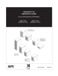
®
Symmetra LX
200/208/230 V, 4–16 kVA
Operations Manual
®
Symmetra LX
Rack-mount UPS
Symmetra® LX
Rack-mount
Extended Run
®
Symmetra LX
Tower UPS
®
Symmetra LX
Tower
Extended Run
®
®
990-1546, English, January 2004
TABLE OF CONTENTS
Chapter 1: Overview................................................................................................................. 1
PowerView................................................................................................................................................................. 1
Navigation ............................................................................................................................................................. 1
Functions............................................................................................................................................................... 2
Chapter 2: Getting Started....................................................................................................... 3
Turning on the UPS ................................................................................................................................................... 3
Powering Up the Load Equipment ............................................................................................................................. 4
Powering Down the Load Equipment ........................................................................................................................ 5
Bypass Operation ...................................................................................................................................................... 6
Language Setting ...................................................................................................................................................... 7
Chapter 3: Menu Commands ................................................................................................... 9
Command Reference ................................................................................................................................................ 9
Accessories Menu ................................................................................................................................................. 9
Control Menu......................................................................................................................................................... 9
Display Menu....................................................................................................................................................... 10
Diagnostics Menu ................................................................................................................................................ 11
Help Menu ........................................................................................................................................................... 11
Logging Menu...................................................................................................................................................... 11
Status Menu ........................................................................................................................................................ 12
Setup Menu ......................................................................................................................................................... 13
Chapter 4: Messages ............................................................................................................. 15
Troubleshooting....................................................................................................................................................... 15
Chapter 5: Maintenance ......................................................................................................... 21
Service .................................................................................................................................................................... 21
Copyright and Trademark Information
Entire contents copyright © 2004 by APC Corporation. All rights reserved. Reproduction in
whole or in part without permission is prohibited.
APC, Symmetra, and InfraStruXure are registered trademarks of APC Corporation.
All other trademarks are the property of their respective owners.
CHAPTER 1: OVERVIEW
PowerView
This manual contains information on how
to operate the UPS using the PowerView
user interface.
PowerView provides the ability to control,
configure, and monitor the UPS.
Figure 1: Typical PowerView Display
Navigation
Eight (8) PowerView Display menus allow you to perform functions and commands.
Menu
Description
Control
Provides power control commands, such as Load ON and Load OFF.
Status
Displays information regarding load, battery and power modules, voltage and
electrical current.
Setup
Allows the user to customize the UPS functionality.
Accessories
Allows monitoring of installed APC accessories, if they are present.
Logging
Provides ability to log system events.
Display
Allows configuration of PowerView display settings.
Diagnostics
Provides detailed information useful in troubleshooting the system.
Help
Provides access to help information.
1
CHAPTER 1: OVERVIEW
Functions
PowerView includes an alphanumeric
display, navigation keys, status
indicators, and an audible alarm.
The tables below describe the status
indicators and how to navigate between
PowerView menus.
Figure 2: Display Panel
Status Indicator
Color
Status
LOAD ON
Green
The UPS is supplying power to the load. It may be operating in any
one of the following modes: On-Line, On-Battery, Command-Bypass,
or Maintenance.
ON BATT
Yellow
A mains power failure has occurred, and the battery modules are
supplying power to the load equipment.
BYPASS
Yellow
Power to the load is being supplied directly by the mains power
source. The UPS is removed from the circuit.
FAULT
Red
The UPS has detected an internal fault condition. An alarm message
will appear on the PowerView display.
Navigation
Keys
ESC
Name
Sound
Function
Up
Short beep
Moves the selection arrow upward.
Down
Short beep
Moves the selection arrow downward.
Escape
Short beep
Exits the current screen and returns to the previous
screen.
Programming mode only: when pressed until a
short beep (up to one second) occurs, it exits the
programming mode.
?
ESC + ?
+
Help
Short beep
Opens context-sensitive help.
Enter
Short beep
Opens the selected menu item or setting.
Escape +
Two short
beeps
When pressed simultaneously for about 1 second,
resets the PowerView RM interface.
One long beep
When pressed simultaneously for about 3 seconds,
puts the interface in programming mode for
installing new language program files.
Help + Enter
2
CHAPTER 3: MENU COMMANDS
Turning on the UPS
Follow the steps below to turn ON the UPS.
1.
Turn ON AC utility power to the UPS.
2.
Perform this step if your configuration has
loads.
a)
If load(s) are hardwired , ensure that
each output circuit breaker in distribution
panels are turned ON.
or
b)
3.
Turn ON the UPS input circuit breaker .
4.
Turn ON the UPS System Enable switch .
5.
After initialization, the Monitoring Screen appears, providing a concise view of key
operating parameters.
Chg100%
▌▌▌▌▌▌▌▌▌
Load 000% --------220 Vin 000 Vout 60Hz
Runtime: 00hr 30min
• The factory default
Monitoring screen is
shown. Your actual screen
may vary.
• After the PowerView has
been inactive for 10
minutes (user settable), the
display will revert to the
Monitoring screen.
>Control
Logging
Status
Display
Setup
Diags
Accessories
Help
3
If load(s) are plugged into the UPS ,
ensure that each UPS PDU output circuit
breaker is turned ON.
Chg
Percentage of battery capacity
available
Load
Percentage of power capacity
used
Vin
Input voltage
Vout
Output Voltage
Hz
Output Frequency
Runtime
Runtime expected based on
battery capacity and connected
load
6.
At the Monitoring screen, press any navigation
key to open the Main Menu . This menu
provides access to various submenus.
7.
To open a submenu, move the selection arrow
to its item and press the ENTER key.
CHAPTER 3: MENU COMMANDS
Powering Up the Load Equipment
Follow the steps below to turn ON the output of the UPS and power the load equipment.
>Control
Logging
Status
Display
Setup
Diags
1.
Use ‘ESC’ to view to Main Menu , and then
select CONTROL.
2.
Scroll down and select the TURN UPS
OUTPUT ON command.
3.
Confirm choice by selecting YES .
4.
You will hear some clicking sounds and see
message .
Accessories Help
Graceful Turn Off
Start Runtime Cal
In approximately 90 seconds, you will see
message , and the green LOAD ON status
indicator will be ON.
>Turn UPS Output On
Confirm:
Turn UPS ON
CANCEL
> YES, Turn UPS ON
UPS HAS BEEN
COMMANDED TO TURN
LOAD POWER ON
UPS LOAD IS ON
Press any key...
4
CHAPTER 3: MENU COMMANDS
Powering Down the Load Equipment
Follow the steps below to turn OFF the output of the UPS and power down the load equipment.
>Control
Logging
Status
Display
Setup
Diags
1.
Use ‘ESC’ to view to Main Menu , and then
select CONTROL.
2.
Scroll down and select the TURN UPS
OUTPUT OFF command.
3.
Confirm choice by selecting YES .
4.
You will hear some clicking sounds and see
message .
5.
In approximately 90 seconds, you will see
message , and the green LOAD ON status
indicator will be OFF.
The output is now OFF.
6.
To fully power down the UPS, turn OFF the
System Enable switch, and open the input
circuit breaker.
Accessories Help
Graceful Turn Off
Start Runtime Cal
>Turn UPS Output Off
Confirm:
Turn UPS OFF
NO, ABORT
> YES, Turn UPS OFF
UPS HAS BEEN
COMMANDED TO TURN
LOAD POWER OFF
UPS LOAD IS OFF
Press any key...
5
CHAPTER 3: MENU COMMANDS
Bypass Operation
The bypass operation can be performed manually using the Maintenance Bypass Switch, or automatically using
the PowerView to issue Commands.
Command Bypass Procedure:
The Command Bypass operation is done using commands on the PowerView display.
This procedure is done when you want to bypass the UPS to directly supply power to the load while the
UPS and input circuit breaker are turned ON.
Follow the steps below to directly connect the output of the UPS to the branch circuit (mains) using the command
bypass operation.
1.
Ensure that the input circuit breaker is
turned ON.
2.
Ensure that the System Enable switch is
turned ON.
3.
Use ‘ESC’ to view to Main Menu , and then
select CONTROL.
4.
Scroll down and select the UPS INTO
BYPASS command.
5.
Confirm choice by selecting YES .
6.
You will see message . In addition, the
green LOAD ON and yellow BYPASS status
indicators will be ON.
>Control
Logging
Status
Display
Setup
Diags
Accessories
Help
>UPS into Bypass
Do Self Test
Simulate Power Fail
Graceful Reboot Confirm:
UPS into Bypass
NO, ABORT
> YES, UPS into Bypass
UPS IS BYPASSED
Press any key...
6
CHAPTER 3: MENU COMMANDS
Bypass Operation (continued)
Maintenance Bypass Procedure:
The UPS Maintenance Bypass switch is also used to supply power to the load.
This procedure is done when you want to manually bypass the UPS to directly supply power to the load
while the input circuit breaker is turned ON
Follow the steps below to directly connect the output of the UPS to the branch circuit (mains) using the
maintenance bypass operation.
1.
Ensure that the input circuit breaker is
turned ON.
2.
Turn ON the maintenance bypass switch .
Language Setting
The factory default language of the user interface is English. You can change the language by downloading new
firmware into the PowerView. French, German, Italian, and Spanish are available on the enclosed CD.
Illustrations are representative. Your configuration may be different from the models shown in this procedure.
To change the user interface language, perform the following steps.
1.
Grab onto the door tabs and gently pull forward and then up to remove the door.
2.
To remove the PowerView display; remove the screws and display from the frame.
7
CHAPTER 3: MENU COMMANDS
3.
Remove the screws securing the display bracket to the PowerView.
4.
Disconnect the UPS cable from the RJ-45 port on the PowerView.
5.
Connect the programming cable (included) between the PowerView and the UPS cable.
• Attach the RJ-45 connector to the port on the rear of the PowerView.
• Connect the female DB-9 connector of the programming cable to a serial port on the computer.
• Attach the UPS cable to the female RJ-45 connector on the programming cable.
6.
Locate the language program file to be downloaded into the UPS.
Each language program file appears on the CD under the folder of its language (françois, español, etc.)
with a .bin extension. Program files for additional language support or code updates may be available
on the APC Web site.
7.
Place the PowerView in programming mode by pressing simultaneously the three keys on the right
(ESCAPE, HELP, and ENTER) for about three seconds, until the PowerView emits a long beep.
• The LCD will display the Programming screen.
• To leave the Programming screen before starting a file transfer (step 6), press ESC until it beeps
(about one second).
8.
Start HyperTerminal or another terminal emulation program on the computer.
• Set the communication parameters to 8 bits, no parity, no flow control, 1 stop bit, and 19,200 bps.
• After establishing a connection, use the Xmodem protocol to transfer the language program file from
the CD or your download folder to PowerView.
• When the file transfer is complete, the PowerView will reset itself and display the Startup screen in
the new language.
9.
If the file transfer fails, PowerView will reset itself. Retry the file transfer by repeating steps 6 and7.
10. Quit the terminal session.
11. Disconnect the programming cable on the RJ-45 port on the PowerView.
12. Connect the UPS cable to the RJ-45 port on the PowerView
13. Install the display bracket to the rear of the PowerView by securing the two screws to the display.
14. With two hands, grip the display and gently snap the tabs onto the frame.
15. .Secure the PowerView display by tightening the two screws to the UPS frame.
8
CHAPTER 3: MENU COMMANDS
Command Reference
The following sections describe the details of each command. Commands are organized according to the menu
hierarchy in the PowerView.
Accessories Menu
The Accessories menu allows you to monitor APC accessories if they are installed. Note that the PowerView
must be connected to the computer interface port at the back of the UPS frame in order to monitor internal
accessories.
Control Menu
Use the Control menu and its submenus to control how power flows to and from the UPS.
Menu Item
Function
Turn UPS Output
On/Off
Controls the delivery of output power to connected equipment.
Do Self Test
Initiates a system of self-testing and diagnostics. An error message is displayed when
a problem is detected.
Simulate Power
Fail(ure)
Simulates a power failure/return to test server’s recognition of failure event.
Graceful Reboot
Initiates a signal for the server to shutdown. After user-defined “Low-Battery Duration”
plus “Shutdown Delay,” the output power is switched off for the duration of the userdefined “Return Delay.” Then the output power is switched on again. See SetupShutdown to set these time delays.
PowerChute software must be used on the server for it to be properly shutdown.
Graceful Turn Off
Initiates a signal for the server to shut down. After the user-defined “Low-Battery
Duration” plus “Shutdown Delay,” the output power is switched off. Use the SetupShutdown menu to set these times.
PowerChute software must be used on the server for it to be properly shutdown.
Start/Stop
Runtime
Cal(ibration)
Calculates an accurate battery runtime measurement. Delivers load output power from
battery source. Discharges battery to 25% of capacity. Battery capacity must be at
100% to execute this test.
UPS into/out of
Bypass
Controls the bypass function. When in the bypass mode, power is delivered directly
from utility source to load equipment.
9
CHAPTER 3: MENU COMMANDS
Display Menu
The Display menu lets the user customize the PowerView display.
Display
Date/Time
Function
Sets the correct date and time.
Options
Date: dd-mmm-yyyy
EX:11-Aug-2003
Time: hh:mm:ss
EX: 21:36:10
Password
Protects against unauthorized
configuration changes.
Password
Sets a password.
Valid characters include:
A–Z, or 0–9;
type ‘_’ to complete.
Timeout
Sets the inactivity timer.
1, 2, 5, 10(default); 30 minutes;
1, 2, or 4 Hours;
or Forever
Invalidate
Puts password into effect. Prevents
unauthorized changes to the UPS
configuration.
Information
Displays PowerView model number,
serial number, date of manufacture,
and revision information.
Beeper
Sets audible alarm (beeper) criteria.
At UPS
Not used with the UPS.
At Display
Sets parameters for the audible alarm
in the PowerView.
Power Failure,
Power Failure +30 seconds,
Low Battery, or Never
Volume
Sets audible alarm volume.
Off, Low(default), Medium,
or High
Click
Sets sound when pressing display
buttons.
On(default), Off
Contrast
Sets LCD screen contrast.
0,1,2,3,4,5,6, or 7
Config
Customizes the information displayed
on the Startup screen.
Use factory defaults when
possible.
10
CHAPTER 3: MENU COMMANDS
Diagnostics Menu
The Diagnostics menu provides information for use in troubleshooting.
Menu Item
Function
Fault and Diagnostics
Displays current system fault and diagnostic information of that fault.
(Main) Intelligence Module
Displays detailed intelligence module status and information.
Redundant Intelligence
Module
Displays detailed redundant intelligence module status and information.
Power Modules
Displays detailed power module status and information.
Batteries
Displays detailed battery module status and information.
Help Menu
To access PowerView online help screens, press the SCROLL UP and SCROLL DOWN keys simultaneously to access
context sensitive help.
Logging Menu
The Logging menu lets you customize the UPS log.
Menu Item
Function
View Log
Logs the most recent 64 events. Point to an entry and press the ENTER
key for more information on that event.
View Statistics
Records the total number of transfers to battery, low battery, faults, and
on-battery runtime events.
Configure Logging
Allows different types of events to be included or excluded from the log.
Event types include Power Events, UPS Controls, UPS Faults, and
User Activity.
Power Events
On (default), Off
UPS Control
UPS Faults
User Activity
Measure UPS Events
11
CHAPTER 3: MENU COMMANDS
Logging Menu (continued)
Menu Item
List Event Groups
Function
Lists the specific events in each group.
Power Events
UPS Control Events
User Activities
UPS Fault Events
Measure UPS Events
Clear Log
Clears the view log. Does not clear the active event lists.
Status Menu
The Status menu displays information regarding load, battery and power modules, voltage, and electrical current.
Menu Item
Function
Ø Vin Vout Iout
Displays input voltage(s), output voltage(s), and output current information.
% load assuming
no redundancy
Compares the current load to the total capacity of all power modules.
% load allowing
for n+ redundancy
Compares the current load to the total capacity of all power modules except the power
modules that are set aside by the “Fault Tolerance” alarm threshold. For example, if
there are four power modules installed, and the fault tolerance alarm threshold is set
to “1,” this percentage of load uses only 3 power modules for the calculation. See
Setup-Alarms to set the redundancy level.
Frequencies
Displays the measured input and output frequencies.
Battery Status
Screen
Displays battery module capacity, runtime, and status information.
Power Module
Status Screen
Displays power module capacity, fault tolerance, and status information.
Alarm Thresholds
Status Screen
Displays the user-defined alarm settings. See Setup-Alarms to set these alarm
thresholds.
Miscellaneous
Status Screen
Displays the summary result Self Test, Last System Transfer, Operating Mode, and
status of Intelligence and redundant intelligence modules.
12
CHAPTER 3: MENU COMMANDS
Setup Menu
The Setup menu lets the user customize the UPS functionality.
Menu Item
Function
Options
Sets the shutdown parameters in the event of a
utility power failure.
None
Low Batt(ery)
Dur(ation)
Sets the number of minutes an audible alarm
sounds before the UPS shuts down due to
battery exhaustion.
2(default), 5, 7, 10, 12, 15,
18, or 20 minutes
Shutdown Delay
Sets the additional runtime for computer issuing
shutdown command if it needs additional time to
shut itself down.
0, 20(default), 60, 120,
240, 480, 720, or 960
seconds
Return Delay
Sets the delay interval that allows utility power to
stabilize before the system goes back online
after a utility power failure.
0(default), 20, 60, 120,
240, 480, 720, or 960
seconds
Return Battery
Capacity
Sets the minimum battery capacity necessary
before repowering the load when returning from
an extended utility power failure.
0(default), 15, 25, 35, 50,
60, 75, or 90 seconds
Shutdown
Defaults
Sets all settings to factory defaults.
Output Freq(uency)
The UPS output will phase lock to the input
within this range.
13
50 ±3 Hz, 50 ± 0.1 Hz, 60 ±
3 Hz, 60 ± 0.1 Hz, Full
range tracking
CHAPTER 3: MENU COMMANDS
Setup Menu (continued)
Menu Item
Alarms
Function
Options
Sets the alarm thresholds.
None
Redundancy
An audible alarm sounds if the redundancy falls
below this level.
0(default), 1, or 2
Load
An audible alarm sounds when the load exceeds
this limit. (Upper value is limited by the maximum
power of the UPS.)
Never(default), 1, 2, 3, 4, 5,
6, 7, 8, 9, 10, or 12 kVA
Runtime
An audible alarm sounds if the available runtime
falls below this level (Hours:min).
0:0(default),5m, 10m, 15m,
30m, 45m,1h, 2h, 3h, 4h,
5h, 6h, 7h, or 8h
In the unlikely event that both the UPS fails and
the input voltage or line frequency is outside of
normal range, this option lets you choose to go
into Bypass mode or drop the load.
Go to Bypass or
Select the configuration that you wish to move
UPS data into or out of, and t hen select the
direction that you wish to move the data.
Options include:
Configuration Number,
from UPS to Display, and
from Display to UPS.
Bypass
Copy
Note: Copying data between different voltage
versions may not yield optimum results; in
particular, the output voltage selection should be
reviewed by the user. Copying between different
product lines may leave some parameters in the
target UPS set to factory defaults, especially
when copying from a product with less capability
to one with more capability.
Other
Drop Load
Copy command definition
found in Powerview
manual, 990-0142, page
11.
Remaining user-defined settings.
Self Test
The UPS can automatically test itself at this
user-specified interval.
UPS ID
Assigns an eight-character text string to a
system.
Output
Sets output voltage. Selection depends upon
system configuration.
At Power On, 7 days,
14 days(default) , or
Disabled
US/JAPAN:
200V, 208V, 240V
INTERNATIONAL:
220V, 230V, 240V
Vout Reporting
Reports the most significant output voltage.
14
Auto
CHAPTER 4: MESSAGES
Troubleshooting
The PowerView reports various messages on the display, including alarm status and changes in system
configuration. This section lists all the PowerView display messages, what each means, and an appropriate
corrective action.
More than one of these messages may occur at one time. If this happens, be sure to review all of the messages
for a better understanding of the system condition.
PowerView Message
Start-Up
Meaning
#Pwr modules changed
since last ON.
At least one power module has
been added or removed from
the UPS since the last time the
Pwr ON command was issued.
#Batteries changed
since last ON.
At least one battery module has
been added or removed from
the UPS since the last time the
Pwr ON command was issued.
No Redundant
Intelligence Module
(IM).
There is no redundant
intelligence module installed and
working.
Corrective Action
No corrective action
necessary. Proceed with the
startup.
Proceed with the startup or
abort the startup and install
anew IM.
Note: Without two
functioning IMs, there is no
redundancy in the event of
an IM failure.
Batt capacity less than
Return Batt Cap.
Input Freq outside
configured range.
The battery capacity of the UPS
is less than the user specified
minimum battery capacity
required to turn on the load.
Option 1: Abort the startup
and allow batteries to
recharge.
The input frequency to the UPS
is outside the configured range.
The output frequency will not
synchronize with the input
frequency. Normal bypass is not
available. The system will start
on-battery.
Option 1: Improve the
frequency of the incoming
voltage.
Option 2: Continue startup,
with less than minimum
battery capacity.
Option 2: Widen the range
of the acceptable incoming
frequency with the
PowerView.
(Startup>Setup>OuputFreq)
Option 3: Proceed with
startup. Normal bypass is
not available and system
may start on battery power.
15
CHAPTER 4: MESSAGES
PowerView
Message
Start-Up
(continued)
AC adequate for UPS
but not for bypass.
Low/No AC input,
startup on battery.
Meaning
Corrective Action
The UPS will function on-line with
the input voltage, but in the event
that bypass is required, the input
voltage is not adequate to power
the load equipment.
Option 1: Improve the
incoming voltage.
Input voltage is not adequate to
start the UPS. If startup proceeds,
the UPS will function from battery.
Option 1: Abort startup until
acceptable input voltage is
present.
Option 2: Proceed with
startup. Normal bypass is
not available.
Option 2: Proceed with
startup. Battery will be
discharged.
General
Status
# of batteries
increased.
At least one battery module has
been added to the system.
# of batteries
decreased.
At least one battery has been
removed from the system.
# of Pwr Modules
increased.
At least one power module has
been added from the system.
Intelligence Module
inserted.
An intelligence module has been
installed in the lower IM slot.
Intelligence Module
removed.
An intelligence module has been
removed in the lower IM slot
Redundant
Intelligence Module
inserted.
An intelligence module has been
installed in the upper IM slot.
Redundant
Intelligence Module
removed.
An intelligence module has been
removed in the upper IM slot.
# of External Battery
Cabinets increased.
At least one external battery
cabinet has been connected to the
frame.
# of External Battery
Cabinets decreased.
At least one external battery
cabinet has been disconnected
from the UPS.
16
No corrective action
necessary.
CHAPTER 4: MESSAGES
PowerView
Message
General
Status
(continued)
Meaning
Redundancy
Restored.
Power module redundancy loss occurred
and was restored. Either additional
modules have been installed or the load
has been reduced.
Load is No
Longer above
Alarm
Threshold.
The load exceeded the load alarm
threshold. The situation has been
corrected because either the load
decreased or the threshold was
increased.
Min Runtime
restored.
The system runtime dropped below the
configured minimum runtime and was
restored.
Corrective Action
No corrective action
necessary.
Either additional battery modules were
installed, the existing battery modules
were recharged, the load was reduced,
or the threshold was raised.
Module
Failure
Threshold
Alarm
Bad Battery
Module.
A battery module failed and requires
replacement.
Bad Power
Module.
A power module failed and requires
replacement.
Intelligence
Module is
installed and
failed.
The intelligence module in the lower IM
slot has failed.
Redundant
Intelligence
Module is
installed and
failed.
The intelligence in the upper IM slot has
failed.
Load is above
kVA alarm
threshold.
The load has exceeded the user
specified load alarm threshold.
Option 1: Reduce the load.
Redundancy
has been lost.
The UPS no longer detects redundant
power modules. Either power module(s)
failed or the load increased.
Option 1: If possible, install
additional power modules.
Refer to installing modules in
the Physical Installation or
Service Manual.
Option 2: Use the PowerView
interface to raise the alarm
threshold.
Option 2: Decrease the load.
Option 3: Disable the
redundancy alarm by setting
redundancy to zero.
(Startup>Setup>Alarms>
Redundancy>Zero)
17
CHAPTER 4: MESSAGES
PowerView
Message
Threshold
Alarm
(continued)
Redundancy is
below alarm
threshold.
Runtime is below
alarm threshold.
Meaning
Corrective Action
Actual power module redundancy has
fallen below the user specified
redundancy alarm threshold. Either
power module(s) failed or the load has
increased.
Option 1: If possible, install
additional power modules.
The predicted runtime is lower than
the user specified for the minimum
runtime alarm threshold. Either the
battery capacity has decreased or the
load increased.
Option 1: Allow the battery
modules to recharge.
Option 2: Decrease the load.
Option 3: Use the
PowerView to decrease the
redundancy alarm threshold.
(Startup>Setup>Alarms>
Redundancy)
Option 2: If possible,
increase the number of
battery modules.
Option 3: Decrease the load.
Option 4: Use the
PowerView to decrease the
minimum runtime alarm
threshold.
(Startup>Setup>Alarms>
Runtime)
Bypass
Bypass is not in
range (either freq
or voltage).
The frequency and/or voltage are out
of acceptable range for bypass. This
message occurs when the UPS is
online and indicates that the bypass
mode may not be available if required.
The system may start
on-battery.
Option 1: Decrease the
sensitivity to input frequency.
(Startup>Setup>OutputFreq)
Bypass contactor
stuck in bypass
position.
The UPS is positioned in the bypass
position and cannot go on-line.
Call your contract service
provider or APC Technical
Support.
Bypass contactor
stuck in on-line
position.
The UPS is positioned in the on-line
position and cannot go to bypass.
UPS in bypass
due to internal
fault.
The UPS has transferred to bypass
mode because a fault has occurred.
UPS in bypass
due to overload.
The load exceeded the system power
capacity. The UPS has switched to
bypass mode.
Option 1: Decrease the load.
System is in
Maintenance
Bypass.
The UPS is in bypass because the
maintenance bypass switch is in the
On position.
No corrective action
necessary.
18
Option 2: Correct input
voltage to provide
acceptable voltage and/or
frequency.
Option 2: If possible, add
power modules to the
system.
CHAPTER 4: MESSAGES
PowerView
Message
General
Fault
On Battery.
Meaning
Corrective Action
The UPS is in the on-battery mode.
The battery modules are being
discharged.
No corrective action is
necessary.
Need Bat
Replacement.
One or more battery modules are in
need of replacement.
Refer to module
replacement procedure.
UPS Fault.
A fault occurred in a power module.
The UPS Fault message always
occurs when there is a bad power
module failure message.
Call your contract service
provider or APC Technical
Support.
Shutdown or unable
to transfer to Batt due
to overload.
The UPS has shutdown because
an overload occurred and bypass is
not available.
Option 1: Reduce the load
to eliminate overload.
Note: Runtime is limited in
duration. Prepare to
shutdown the UPS and the
load equipment, or restore
incoming voltage.
Option 2: If possible, add
power modules to eliminate
overload.
Option 3: Replace failed
power modules to eliminate
overload.
Note: If bypass is not
available because of a
power failure, wait for power
to be restored. If there is a
utility problem, have it
corrected.
Load Shutdown from
Bypass. Input
Freq/Volts outside
limits.
The UPS shut the load down while
it was on bypass, because the input
power went out of acceptable
range.
Correct the input voltage
problem.
Fault, Battery Charger
Failure.
The battery charger in one or more
power module(s) failed.
Refer to module
replacement procedure.
Fault, Bypass Relay
Malfunction.
The bypass relay has
malfunctioned.
Call your contract service
provider or APC Technical
Support.
Fault, Internal Temp
exceeded normal
limits.
The temperature of one or more
battery modules is too hot.
Replace overheated
module. Refer to module
replacement procedure.
19
CHAPTER 4: MESSAGES
PowerView
Message
General
Fault
(continued)
Input circuit breaker
tripped open.
Meaning
The input circuit breaker on the
UPS tripped open. Input voltage is
disconnected to the UPS.
Corrective Action
Option 1: If this occurs in
conjunction with an overload
condition, decrease the load
and reset the breaker.
Option 2: If no overload
condition exists, reset
breaker. If it trips open
again, call your contract
service provider or APC
Technical Support.
System level fan
failed.
A cooling fan in the UPS frame
failed.
Call your contract service
provider or APC Technical
Support.
The Redundant
Intelligence Module
(IM) is in control.
The intelligence module in the
lower IM slot has failed or is not
installed. The intelligence module in
the upper IM slot is managing all
activity.
Replace the intelligence
module. Refer to module
replacement procedure.
IIC inter-module
communications
failed.
The communications between the
MIM and at least one other module
failed.
Call your contract service
provider or APC Technical
Support.
20
CHAPTER 5: MAINTENANCE
Service
If the UPS requires service, do not return it to the dealer! Follow these steps:
1.
Review the problems discussed in the Messages chapter to eliminate common problems.
2.
Verify that no circuit breakers are tripped. A tripped circuit breaker is the most common UPS problem!
3.
If the problem persists, call customer service.
• If the UPS is under warranty, repairs are free. If not, there is a repair charge.
4.
Pack the UPS in its original packaging. If the original packing is not available, ask customer service
about obtaining a new set.
5.
Pack the UPS properly to avoid damage in transit. Never use polystyrene beads for packaging.
Damage sustained in transit is not covered under warranty.
6.
Mark the RMA# on the outside of the package.
www.APCturkey.com
21