1
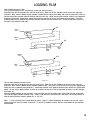
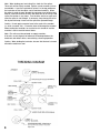
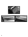
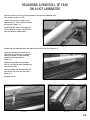
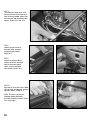
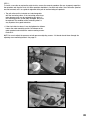
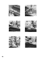
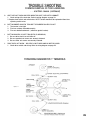
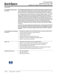
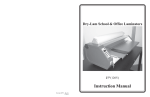
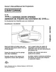
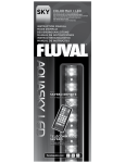
Thread the top roll of film under the idler roller as shown in the
threading diagram on previous page (see Figure 9-4). Pull the
film down so that the films lead edge is below the lower heat
shoe. Next thread the bottom roll of film under the lower idler
bar pulling film upward until it is even with the top heat shoe
(the film will overlap). Tape it to the top film edge. This creates
a film “Web” (Photo 10-1 & 10-2).
Photo 10-1
Using Tension Adjustment knobs, loosen tension on both rolls
of laminating film. Turn on the “Drive” switch and using the
threading board—push the film web into the laminating rollers.
This process will push the web into the pull rollers and exit.
Ensure that the threading board and film exit between the rear
pull rollers (Photo 10-3 & 10-4).
Photo 10-2: Creating Film Web
NOTE: If you lose your threading board or if it becomes damaged, you can make your own with a piece of poster board.
Cut poster board 12” wide by
the length of the laminator (27”).
Your laminator is now loaded and ready to be heated. Remove
the threading board and save for your next use.
Photo 10-3: Threading board and film web entering.
Photo 10-4: Threading board and film web exiting pull rollers.
10