1
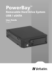
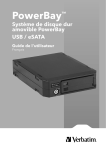
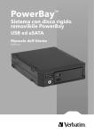
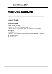
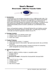
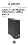
Verbatim PowerBay™ 4-Bay RAID
Multi-Interface Drive
Version 1.00
User Manual
Table of Contents
Introduction.......................................................................................................................... 2
Package Contents. ............................................................................................................ 2
Controls, Connectors and Indicators..................................................................... 2
About the Hard Drive...................................................................................................... 4
Locating the Drive on Your Desk. ............................................................................ 4
Bundled Software............................................................................................................. 4
Acronis Backup Software (Windows)............................................................................ 4
MachUSB Handler (Windows and Macintosh).............................................................. 4
RAID Monitor (Windows). ............................................................................................ 4
FAT32 Formatting Utility (Windows)............................................................................. 5
Configuring the RAID Mode....................................................................................... 5
RAID 0......................................................................................................................... 5
RAID 1+0 (RAID 10)..................................................................................................... 5
RAID 5......................................................................................................................... 5
RAID Setting Steps....................................................................................................... 5
Connecting To Your Computer.................................................................................. 6
Disconnecting Your Hard Drive................................................................................ 6
For Windows Users...................................................................................................... 6
For Mac OS Users. ....................................................................................................... 7
Replacing a Failed Cartridge...................................................................................... 7
Rebuilding the Array....................................................................................................... 8
Rebuilding RAID 5 and RAID 1+0. ............................................................................... 8
Rebuilding RAID 0....................................................................................................... 8
Getting Help......................................................................................................................... 8
Limited Warranty Terms. ............................................................................................... 8
Return Procedures. ...................................................................................................... 9
Rights........................................................................................................................................ 9
FCC Compliance................................................................................................................. 9
Introduction
Thank you for purchasing this Verbatim PowerBay™ 4-Bay RAID multi-interface drive. “RAID” is short for
“Redundant Array of Independent Disks” and is a standard method of combining two or more hard disk drives to
achieve higher levels of performance, reliability and capacity. Before you begin to use the drive, there are a few
important things to learn about your new product.
Package Contents
• PowerBay 4-Bay RAID multi-interface drive • Front Panel Lock Key (2 each)
• AC Power Cord
• USB 2.0 Cable
• User Guide
• CD-ROM containing software and documentation
• FireWire 9-pin to 9-pin cable (1394b Beta)
• FireWire 9-pin to 6-pin cable (1394b Bilingual)
• eSATA Cable
Controls, Connectors and Indicators
First familiarize yourself with the features of the unit.
Front Panel Area
The front panel contains various LEDs and several important buttons and locks. Refer to the diagram below.
5
6
7
8
1
9
2
3
4
1. Status LED. This LED will change color to indicate one for four different device states:
a)Red: The unit is in standby state. In this state, the power cable is plugged into a power source although
the main device power remains off.
b)White: The unit is powered on and configured in RAID 5 mode.
c)Purple: The unit is powered on and configured in RAID 1+0 mode.
d)Blue: The unit is powered on and configured in RAID 0 mode.
2. Power Button. To turn on the product, press and hold the Power Button for at least 3 seconds. To turn off
the product, press and hold again for at least 3 seconds. For further information, read below to see how the
Auto Power Mode can be used to turn power on and off automatically.
2
Product Overview
3. Function Button. The Function Button is used for two purposes:
a)Use this button to cycle through RAID options when setting the RAID mode (see Configuring the RAID
Mode below).
b)Use this button to initiate rebuilding the array after replacing a failed cartridge (see Rebuilding RAID 5
and RAID 1+0 below).
4. Cartridge Key Lock. Turn key counterclockwise to the Lock position to lock all cartridges in place. Turn
key clockwise to the Unlock position to unlock all cartridges.
5. Cartridge Slide Lock. Slide locking button to the left to lock the cartridge in place. Slide locking button to the right
to unlock the cartridge.
6. Cartridge Status LED. The LED indicates the operational state as follows:
Blue On: Disk is ready.
Blue Flashing: Disk is being accessed.
Red: Disk not formatted or disk error.
7. Disk Label. This area is reserved for applying an optional label.
8. Handle. To slide out a cartridge, please grab this area of the cartridge.
9. Cartridge Slots. This product accepts 4 disk cartridges.
Rear Panel Area
The rear panel contains the data and power connectors, as well as a few important switches.
10. Product Label. This label contains your product model number.
11. Main Fan. This is one of two fans used for cooling.
12. FireWire 800 Connectors (two provided). Use either of these two connectors to attach the drive to
your computer via FireWire 800 or FireWire 400. One of the two connectors may be used to daisy-chain to
another FireWire device.
13. USB Port (B type). Use this connector to attach the drive to your computer via USB.
14. eSATA Port. Use this connector to attach the drive to your computer via eSATA. Alternatively, you may connect
to a PowerBay NAS array product over eSATA as a high speed means of backing up your NAS array.
3
Product Overview
15. RAID Setup Button. This recessed button is used to initiate reconfiguration of the RAID mode. To access and depress the button, use a pointed tool or pen point. See Configuring the RAID Mode below for a
description of how to use this button.
WARNING: Changing RAID mode will delete all data on the drive. Do not press this button to change
RAID mode unless you have first saved all of the data from the drive to another storage location.
16. AUTO Power Switch. This switch is used to enable the Auto Power Mode feature. Use a pointed tool
or pen point to change the slide switch position. The two switch settings are:
• POWER MODE ON: (Default) In this setting, the device power is controlled fully by the front Power Button.
• POWER MODE AUTO: In this setting, the device power will follow the power state of the connected host
computer. When the computer is powered on, the drive will power on. When the computer is powered
off, the drive will power off.
17. Security Hook. The unit can be physically secured by attaching a strong cable to this hook.
18. Kensington Slot. Use this slot with a compatible Kensington Lock as an anti-theft measure.
19. Secondary Fan. This is one of two fans used for cooling.
20. Power Connector. Connect the supplied power cord to this connector.
About the Hard Drive
The hard drive comes pre-formatted in FAT32 format. This format allows for operation with either Windows or Mac OS.
Note: Capacity dependent on model. 1 MB = 1,000,000 bytes/1 GB = 1,000,000,000
bytes/1 TB = 1,000,000,000,000 bytes. Some capacity used for pre-loaded software,
formatting and other functions and thus is not available for data storage. As a result,
and due to differing calculation methods, your operating systems may report as
fewer megabytes/gigabytes/terabytes.
Locating the Drive on your Desk
Place the drive on a sturdy desk or table that is free from clutter that could block airflow around the unit. The drive
can be used in either the horizontal or vertical position. Please install the attachable rubber feet as shown below
depending on which orientation you prefer. In either orientation, take care not to block any air vents.
Bundled Software
The included CD-ROM contains copies of the User Guide, as well as four optional software utilities: (1) Acronis
backup software, (2) MachUSB handler to improve USB transfer speed, (3) RAID Monitor to display current RAID
configuration parameters, and (4) FAT32tool, which may be used to format the array to FAT32.
Acronis Backup Software (Windows)
Acronis backup software is included on CD-ROM. To install this application on your Windows computer, open the Acronis folder on the CD and then double click the setup file to start installation. The Acronis installation window will appear.
Follow the setup wizard to install the software. User documentation can also be found on the CD.
MachUSB Handler (Windows and Macintosh)
To install this application on your Windows or Macintosh computer, open the MacUSB folder on the CD and double click
the installation file. The handler will remain active in the background and will accelerate USB data transfers whenever
your PowerBay single bay drive is attached.
RAID Monitor (Windows)
To install this application on your Windows computer, open the RAIDMon folder on the CD and then double click the
setup.exe file to start installation. The application can be launched from its icon in the system tray.
4
Product Overview
FAT32 Formatting Utility (Windows)
To install this application on your Windows computer, open the FAT32tool folder on the CD and then double click the fat32tool.exe file to run the FAT32 formatting utility.
Configuring the RAID Mode
This Verbatim 4-bay RAID drive can be configured to one of three RAID modes. The factory default setting is RAID 5. If RAID
5 is your desired mode, then you can jump to the next section of the manual since no further configuration is required.
WARNING: Changing RAID mode will delete all data on the drive. Do not press the RAID Setup button to
change RAID mode unless you have first saved all of the data from the drive to another storage location.
RAID 0
RAID 0 (also called Striping) distributes data across both disks in a way which can improve throughput, while retaining
full capacity. However, in case of possible failure of any disk, all data will be lost and the array will no longer mount to
your computer. Available capacity is the combined capacity of all four drive cartridges.
If any disk fails in RAID 0 then the LED of the failed drive will change to RED.
RAID 1+0 (RAID 10)
Commonly referred to as RAID 10, RAID 1+0 (striping of mirror pairs) provides fault tolerance and improved performance. This mode creates a striped set from two sets of mirrored drives. If a disk fails all the remaining disks continue to
be used. The array can sustain multiple drive losses so long as neither mirrored pair loses both of its drives.
Available capacity is equal to that of only two of the four included cartridges.
If a disk cartridge fails, then the LED corresponding to the failed disk will change to RED.
RAID 5
RAID 5 (Striping with distributed parity) combines four disks in a way that protects data against loss of any one disk. The
storage capacity of the array is reduced by one disk.
RAID Setting Steps
To change RAID mode, follow these steps:
1. If you have any important data stored on the drive, first save the data to another storage location.
2. While power is ON, use a pointed tool or pen point to depress and hold the RAID Setup button for at least 3 seconds.
3. Note the color of the front panel status LED. Press the front panel Function Button one or more times to
cycle to the LED color corresponding to the desired RAID mode:
Blue = RAID 0
Purple = RAID 1+0
White = RAID 5
4. Again, depress and hold the RAID Setup button for at least 3 seconds. The cartridge LEDs will begin flashing
blue to indicate that the array is being rebuilt to the new RAID mode. When flashing turns to solid blue the drive
has successfully reconfigured, though remains uninitialized, unpartitioned and unformatted.
5. You must now initialize, partition and format the drive array. Attach the drive to your host computer using
either USB, eSATA or FireWire. Your computer may show it as an unknown device, which confirms that the
drive remains uninitialized, un-partitioned and unformatted.
6. Partition and format the drive using the appropriate tools:
• For NTFS, use Windows tools (right-click on My Computer and select Manage / Storage / Disk Management).
• For HFS+, use Mac OS tools (Disk Utility). Note: For Intel-based Macs select GUID Partition Table for array sizes
larger that 750GB.
• For FAT32, use the FAT32 formatting utility supplied on the included CD-ROM.
You can find more information on formatting from the support web site listed under Getting Help.
7. When formatting is complete, confirm that the drive has mounted properly and a new drive icon appears in
My Computer (Windows) or a new icon appears on the desktop (Mac).
5
Product Overview
Connecting to your Computer
This Verbatim external hard drive provides four available connection protocols: eSATA, USB, FireWire 400 or
FireWire 800. You can attach your drive to a computer with any of these connections, but do not attempt to use
more than one connection type at the same time.
Connecting your drive to a computer is extremely simple. Follow the steps below.
1. Connect the included AC Adapter to the drive and then to a wall outlet.
2. Next, press and hold the Power Button for at least 3 seconds to turn on the drive.
3. Finally, connect one, and only one, of the following data cables.
• USB: Connect the included USB cable from the USB port on the drive to an available USB port on your
computer.
• FireWire 400: Connect the included 6-pin-to-6-pin FireWire cable from the FireWire 400 port on the drive to
an available FireWire 400 port on your computer.
• FireWire 800: Connect the included 9-pin-to-9-pin beta cable from one of the FireWire 800 ports on the
drive to an available FireWire 800 port on your computer.
• eSATA: Connect the included eSATA cable from the eSATA port on the drive to an available eSATA port on
your computer.
4. The hard drive will mount automatically, and a new icon will appear in My Computer (Windows) or a new icon
will appear on the desktop (Mac).
Depending on your computer’s operating system and the interface type you are using, the following special notes may apply:
Note 1: USB under Windows. If you are using a USB 1.1 port on your Windows computer, the following
cautionary note may appear on your display: Hi-Speed USB Device plugged into non-Hi-Speed USB hub. This
does not indicate a problem because the drive is compatible with both USB 1.1 and USB 2.0 ports. Simply close
the message and proceed. However, in this case the drive will operate only at USB 1.1 speeds.
Note 2: USB or FireWire or eSATA under Mac OS X 10.2. Mac OS X version 10.2 will not mount any single
FAT32-formatted (MS-DOS) partition greater than 128GB. To work around this OS limitation, you may partition the drive
into smaller FAT32 partitions, or you may reformat the drive to HFS+ format.
Note 3: eSATA. Though the eSATA interface standard provides for “hot-plugging” of the drive, some computers
may not follow the standard precisely. If you find that your drive does not mount after attaching to a computer that is
powered on, shut down the computer, attach and power on the drive; then boot up your computer.
Disconnecting your Hard Drive
Your external hard drive is hot-swappable. It can be connected and disconnected without restarting your computer.
To disconnect your drive at any time, perform the following steps below. You can also disconnect your hard drive at
any time while your computer is powered off.
Note: Please be careful to follow the correct procedure when disconnecting your unit. Simply unplugging the unit
without first following the instructions below may result in damage to your unit and/or loss of data.
For Windows Users:
1. If you have files located on your drive open in any applications, close them.
2. Click the Unplug or Eject Hardware button in the System Tray.
3. Select your drive from the menu that appears.
4. After a moment, Windows will display a message that your hardware can be safely removed.
6
Product Overview
For Mac OS Users:
1. If you have files located on your drive open in any applications, close them.
2. Locate the icon for your drive on the desktop, and drag it to the trash.
Replacing a Failed Cartridge
When the system detects a failed cartridge, the Cartridge Status LED of the failed cartridge will turn Red. Note
the position of the failed cartridge and replace it with a good cartridge of the same capacity. The cartridge may
be replaced either with power on or power off.
To replace the cartridge, follow these steps:
1
Use the supplied key to unlock the
primary locking mechanism of the
four disk array.
2
Slide the Cartridge
Slide Lock of the failed
cartridge to the right to
unlock that cartridge.
3
Grasp the cartridge handle and
carefully slide the cartridge out
of the array housing.
4
Insert the replacement cartridge
and reverse the steps to secure the
Cartridge Slide Lock and Key Lock.
7
Product Overview
Rebuilding the Array
After replacing a cartridge, the unit will attempt to rebuild the array. How this proceeds depends on the RAID mode
as described below.
Rebuilding RAID 5 and RAID 1+0
If a single cartridge has failed and has been replaced and the unit is set to either RAID5 or RAID1+0 mode, the unit
will initiate a rebuild without data loss. After the failed drive has been replaced with a new cartridge, the LED of the
new cartridge will begin flashing purple. Upon seeing this signal, press and hold the Function Button for at least 3
seconds to continue with the rebuild process. While the rebuild is in process, the Cartridge Status LEDs will flash.
Please allow the rebuild to proceed to completion, at which point the Cartridge Status LEDs will turn solid blue. The
rebuild process can take a long time to complete.
Rebuilding RAID 0
If one or more cartridges fail in RAID0 mode, then all data is lost. You must replace the failed cartridge(s) and follow
the steps above (RAID Setting Steps 5-7) to initialize, partition and format the array.
Getting Help
If you are experiencing difficulty installing or using your Verbatim product, please visit the main Technical Support website at www.verbatim.com/support.
Limited Warranty Terms
The Verbatim Americas, LLC warranty obligations for this hardware product are limited to the terms set forth below:
Verbatim warrants its products to be free of defects in material and workmanship under normal use and service for
a period of 3 years from the date of purchase. Verbatim’s sole obligation with respect to claims of non-conformance
made within the warranty period described above shall be, at its option, to repair or replace any item of Equipment
that Verbatim, in its sole discretion, determines to be defective, subject to the procedure set forth below.
Verbatim’s warranty obligations hereunder are expressly conditioned upon:
• the Products being properly installed, used and maintained at all times by Customer;
• the Products not being subject to unusual mechanical stress or unusual electrical or environmental
conditions or other acts of God;
• the Products not being subjected to misuse, accident or any unauthorized installation/deinstallation by
Customer or other third party;
• the Products not being altered or modified in an unauthorized manner, unless approved in writing or
otherwise performed by Verbatim and
• Customer promptly installing all Product revisions that have been released for such Products by Verbatim
throughout the warranty term.
Verbatim does not warrant that the Products will operate in any specific combination that may be selected for use
by Customer or that the operation of the Products will be uninterrupted or error free, or that all non-conformance or
defects will be remedied. Additionally, Verbatim shall have no warranty obligations for any failure of the Products
to conform to the applicable product specifications resulting from the combination of any Product(s) with hardware
and/or software not supplied by Verbatim. If it is determined that any Product(s) reported as defective or nonconforming by Customer during the warranty period is not defective or non-conforming, Verbatim may, at its option,
charge Customer for any labor provided and expenses incurred by Verbatim in connection with such determination,
at Verbatim’s then current rates. Verbatim is not liable for any damage to or loss of any programs, data, or other
information stored on any media contained within the Verbatim hardware product, or any non-Verbatim product or
part not covered by this warranty. Recovery or reinstallation of programs, data or other information is not covered under this Limited Warranty. Verbatim shall not be responsible for unauthorized sale or misrepresentation by
unauthorized third party resellers. Verbatim warranties are not transferable with ownership. Products purchased by
auction, yard sale, flea market or purchased as demo units may not be covered under Verbatim’s warranty.
8
Warranty
THE WARRANTIES OF VERBATIM AND REMEDIES OF CUSTOMER SET FORTH IN THIS SECTION ARE EXCLUSIVE
AND ARE GIVEN BY VERBATIM AND ACCEPTED BY CUSTOMER IN LIEU OF ANY AND ALL OTHER WARRANTIES,
WHETHER EXPRESSED OR IMPLIED, INCLUDING WITHOUT LIMITATION, ALL WARRANTIES OF MERCHANTABILITY AND FITNESS FOR A PARTICULAR PURPOSE, ALL SUCH OTHER WARRANTIES BEING HEREBY EXPRESSLY
AND UNEQUIVOCALLY DISCLAIMED BY VERBATIM AND WAIVED BY CUSTOMER TO THE EXTENT ALLOWED BY
LAW (AND TO THE EXTENT NOT WAIVABLE BY LAW, ARE LIMITED TO THE TERM OF THE EXPRESS WARRANTY
SET FORTH HEREIN). VERBATIM IS NOT RESPONSIBLE FOR DIRECT, SPECIAL, INCIDENTAL OR CONSEQUENTIAL
DAMAGES RESULTING FROM ANY BREACH OF WARRANTY OR CONDITION, INCLUDING ANY COSTS OF RECOVERING OR REPRODUCING ANY PROGRAM OR DATA STORED IN OR USED WITH THE VERBATIM PRODUCT.
VERBATIM SPECIFICALLY DOES NOT REPRESENT THAT IT WILL BE ABLE TO REPAIR ANY PRODUCT UNDER THIS
LIMITED WARRANTY OR MAKE A PRODUCT EXCHANGE WITHOUT RISK TO OR LOSS OF PROGRAMS OR DATA.
THIS WARRANTY GIVES YOU SPECIFIC LEGAL RIGHTS, AND YOU MAY ALSO HAVE OTHER RIGHTS WHICH VARY
FROM STATE TO STATE. FOR EXAMPLE, SOME STATES DO NOT ALLOW LIMITATIONS ON HOW LONG AN IMPLIED
WARRANTY LASTS, OR THE EXCLUSION OR LIMITATION OF INCIDENTAL OR CONSEQUENTIAL DAMAGES, SO
THESE RESTRICTIONS MAY NOT APPLY TO YOU.
Return Procedure:
The Customer shall obtain a Return Merchandise Authorization (RMA) number from Verbatim prior to returning any
Equipment to Verbatim under this warranty by contacting Technical Support (see www.verbatim.com/support). The
Customer shall prepay shipping charges for Equipment returned to Verbatim for warranty service, and Verbatim shall
pay freight charges for the return of the Equipment to the Customer, excluding customs duties or taxes, if any. All returns
require a dated original proof of purchase and a letter explaining the problem. Before you deliver your product for
warranty service it is your responsibility to backup all data, including all software programs. You will be responsible for
reinstalling all data. Data recovery is not included in the warranty service and Verbatim is not responsible for data that
may be lost or damaged during transit or a repair.
Verbatim will not be responsible for items returned without an RMA or improperly packaged. Replacement
Equipment shall be new or like new in performance and shall be warranted for the remaining duration of the
warranty term of the non-conforming Equipment. All replaced Equipment shall become the property of Verbatim.
Any claims of defects not made within the warranty period shall be deemed waived by Customer
Rights
Copyright ©2010 Verbatim Americas, LLC. No part of this document may be reproduced in any form or by any
means, for any purpose, without the express written permission of Verbatim Americas, LLC. All rights reserved.
All other brands and product names referenced herein are property of their respective owners.
FCC Compliance
This equipment has been tested and found to comply with the limits for a Class B digital device, pursuant to Part
15 of the FCC Rules. These limits are designed to provide reasonable protection against harmful interference in
a residential installation. This equipment generates, uses and can radiate radio frequency energy and, if not installed and used in accordance with the instructions, may cause harmful interference to radio communications.
However, there is no guarantee that interference will not occur in a particular installation. If this equipment does
cause harmful interference to radio or television reception, which can be determined by turning the equipment
off and on, the user is encouraged to try to correct the interference by one or more of the following measures:
• Reorient or relocate the receiving antenna.
• Increase the separation between the equipment and receiver.
• Connect the equipment into an outlet on a circuit different from that to which the receiver is connected.
• Consult the dealer or an experienced radio/TV technician for help.
9
© Verbatim Americas, LLC, 2010
Verbatim and the V logo are registered trademarks of
Verbatim Americas, LLC.