1
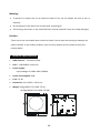
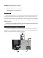
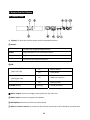
BLED‐7TC BLED‐7TC‐A BLED‐7TC‐B BLED‐7TC‐AB User Guide Please read the instruction carefully before use
Contents 1. Safety Instructions....................................................................................................2 2. Technical Specifications ............................................................................................3 3. Installation................................................................................................................4 3.1 The Method of Connecting Wireless modules ...................................................4 4. How to Set the Fixture..............................................................................................5 4.1 Control Panel ......................................................................................................5 4.2 The Battery Indicator & Charge ..........................................................................6 4.3 Change angle ......................................................................................................6 4.4 Main Function ....................................................................................................7 5. How to Control the Unit .........................................................................................13 5.1 Universal DMX controller .................................................................................14 5.2 Master/Slave operation ....................................................................................14 5.3 Easy Controller (by CA‐8) ..................................................................................14 6. DMX 512 Configuration ..........................................................................................15 7. DMX 512 Connection..............................................................................................16 8. Troubleshooting......................................................................................................17 9. Cleaning And Maintenance ....................................................................................18 1A
1. Safety Instructions Please read the instructions carefully which includes important information about the installation, operation and maintenance. WARNING
y Please keep this User Manual for future consultation. If you sell the fixture to another user, be sure that they also receive this instruction booklet. y Unpack and check carefully there is no transportation damage before using the fixture. y Before operating, ensure that the voltage and frequency of power supply match the power requirements of the fixture. y It’s important to ground the yellow/green conductor to earth in order to avoid electric shock. y Disconnect main power before servicing and maintenance. y Use safety chain when fixes this fixture. Don’t handle the fixture by taking its head only, but always by taking its base. y Maximum ambient temperature is Ta : 40℃. Don’t operate it where the temperature is higher than this. y Unit’s surface temperature may reach up to 85℃. Don’t touch the housing bare‐handed during its operation, and allow about 15 minutes for cooling the unit down before replacing bulb or maintenance as it could be very hot. y In the event of serious operating problem, stop using the fixture immediately. Never try to repair the fixture by yourself. Repairs carried out by unskilled people can lead to damage or malfunction. Please contact the nearest authorized technical assistance center. Always use the same type spare parts. y Do not connect the device to any dimmer pack. y Do not touch any wire during operation and there might be a hazard of electric shock. y To prevent or reduce the risk of electrical shock or fire, do not expose the fixture to rain or moisture. y The housing must be replaced if they are visibly damaged. y Do not look directly at the LED light beam while the fixture is on. 2A
Warning: y To prevent or reduce the risk of electrical shock or fire, do not expose the unit to rain or moisture. y Do not open the unit within five minutes after switching off. y The housing, the lenses, or the ultraviolet filter must be replaced if they are visibly damaged. Caution: There are no user serviceable parts inside the fixture. Do not open the housing or attempt any repairs yourself. In the unlikely situation, your unit may require service, please contact your nearest dealer. 2. Technical Specifications •
DMX Channel:4 channel modes •
LED: 7 x 3W RGB(Tri‐color) LED •
Power Supply: Input Voltage: AC 100V~240V, 50/60Hz •
Power Consumption: 34W •
Fuse: T 6.3A •
Dimension: 243 x 228.5 x 233.5 mm •
Weight: 5.6kgs (BLED‐7TC, BLED‐7TC‐A) 13.6kgs (BLED‐7TC‐B, BLED‐7TC‐AB) 3A
Note: BLED‐7TC (Without Antenna and Battery) BLED‐7TC‐A (With Antenna, without Battery) BLED‐7TC‐B (With Battery, without Antenna) BLED‐7TC‐AB (With Antenna and Battery) 3. Installation The unit should be mounted via its screw holes on the bracket. Always ensure that the unit is firmly fixed to avoid vibration and slipping while operating. Always ensure that the structure to which you are attaching the unit is secure and is able to support a weight of 10 times of the unit’s weight. Also always use a safety cable that can hold 12 times of the weight of the unit when installing the fixture. The equipment must be fixed by professionals. And it must be fixed at a place where is out of the touch of people and has no one pass by or under it. 3.1 The Method of Connecting Wireless modules If you want to insure that the unit has wireless function, you should connect the wireless modules (A) to the motherboard (B) as following ways. The only thing that you should pay more attention is just the red line. Please position it at right place. 4A
4. How to Set the Fixture 4.1 Control Panel ①
Display: To show the various menus and the selected functions. ② Button: MENU To select the programming functions DOWN To go backward in the selected functions UP To go forward in the selected functions ENTER To confirm the selected functions ③LED: MASTER/SLAVE (Red, Left side) On Master Mode Off Slave Mode DMX (Red, Right side) On DMX input present BATTERY (Orange) On Battery status SOUND (Green) Flashing Sound activation ④ Mains output: Connect to supply mains power for the next unit. ⑤ Mains input: Connect to supply mains power. ⑥ Microphone: Receive music for the sound active. ⑦ Only for remote control: By connect to the CA‐8 to control the unit for Stand by, Function and 5A
Mode function. ⑧ DMX output: For DMX512 link, use 3/5‐pin XLR plug cable to link the next unit. ⑨ DMX input: For DMX512 link, use 3/5‐pin XLR plug cable to input DMX signal. ⑩ Power Switch: Turns On/Off the power. 4.2 The Battery Indicator & Charge Battery Indicator:
The LED (Battery indicator) on the front of unit lets you know the current status of the battery: -
When the Orange LED is fully lit the fixture is fully charged. -
When the Orange LED begins flash slowly, the charge is getting low. -
When the Orange LED begins to flash rapidly, it means that the Battery is going to die soon and needs to charge. Note: When the LED indicator starts flashing fast, indicating the battery is about to die, it is the best to stop using the unit, and start charging it. If you let the battery die completely, recharging a completely dead battery is very hard on the unit and will take some time. Battery Recharge: To recharge the battery, plug the charger into the front of the unit and plug the other end into a matching power supply. It takes about 3 hours to reach full charge. 4.3 Change angle For creating a different light show, you can change the angle between the A and B as following: 6A
1, A and B are closed (1); 2, To rotate C button, and change the angle as you required like (2), (3). 4.4 Main Function To select any of the given functions, press the MENU button to show the required option on the display. Select the function with the ENTER button and the display will blink. Use the DOWN and UP buttons to change the mode. Once the required mode has been selected, Press the ENTER button to store. To go back to the main menu without any changes press the MENU button. Hold and press the MENU button about one second or wait for one minute to exit the menu mode. The main functions are shown below: 7A
8A
Color Mode. Press the MENU button up to when the is shown on the display. Pressing ENTER button and the display will blink. Use DOWN and UP button to select the (show 16) or you select (color 1) or … or (manual setting). Once select, press the ENTER button to confirm, if (manual setting), you can press DOWN and UP button to select (green) or (red) or (blue), press ENTER button to confirm, then use DOWN and UP button to adjust the value (0‐255) and press ENTER button to store, automatically return to the main functions without any change after 8 seconds. To go back to the functions without any change press the MENU button again. Dimmer Mode Press the MENU button to show on the display. Press the ENTER button and the display will blink. Use the DOWN and UP buttons to adjust the value from 0%‐100% of the unit. Once selected, press the ENTER button to store. To return to the main menu without any changes press the MENU button. Hold and press the MENU button about one second or wait for one minute to exit the menu mode. Show Mode Press the MENU button up to when the is shown on the display. Pressing ENTER (auto show) or button and the display will blink. Use DOWN and UP button to select the (show 1) or (show 2) or … (show 12). Once the show has been selected, press the ENTER button to confirm, if you select (show 1) or (show 12), you can press DOWN and UP button to select (show 2) or … (slowest) or … (fastest), press ENTER button to store or automatically return to the main functions without any change after 8 seconds. To go back to the functions without any change press the MENU button again. Chase Mode Press the MENU button up to when the is shown on the display. Pressing ENTER 9A
button and the display will blink. Use DOWN and UP button to select the (chase 16) or (chase 1) or … or (fade). Once the chase has been selected, press the ENTER button to confirm, then press DOWN and UP button to select (slowest) or … (fastest), press ENTER button to store or automatically return to the main functions without any change after 8 seconds. To go back to the functions without any change press the MENU button again. Sound Mode Press the MENU button up to when the is shown on the display. Pressing ENTER button and the display will blink. Use DOWN and UP button to select the on) or (sound control (sound control off). Once the mode has been selected, press the ENTER button to setup or automatically return to the main functions without any change after 8 seconds. To go back to the functions without any change press the MENU button again. Sound Sensitivity Press the MENU button to show on the display. Press the ENTER button and the display will blink. Use the DOWN and UP buttons to change the sound sensitivity (0‐100) of the unit. Once selected, press the ENTER button to store. To return to the main menu without any changes press the MENU button. Hold and press the MENU button about one second or wait for one minute to exit the menu mode. DMX 512 Address Setting is shown on the display. Press ENTER button Press the MENU button up to when the and the display will blink. Use DOWN and UP button to change the DMX512 Address (1‐512) or select (auto setting DMX512 address). Once selected, press the ENTER button to store or automatically return to the main functions without any changes after 8 seconds. To go back to the functions without any change press the MENU button again. 10A
Channel mode Press the MENU button up to when the is shown on the display. Pressing the ENTER button and the display will blink. Use the DOWN and UP button to select the mode) or (4 channel mode) or (4 channel mode) or (4 channel (4 channel mode) or (6 channel mode). Once the mode has been selected, press the ENTER button to setup or automatically return to the main functions without any change after 8 seconds. To go back to the functions without any change press the MENU button again. Slave Mode Press the MENU button up to when the is shown on the display. Pressing ENTER button and the display will blink. Use DOWN and UP button to select the (normal) or … or (Mater) or (16 light show) mode. Once the mode has been selected, press the ENTER button to setup or automatically return to the main functions without any change after 8 seconds. To go back to the functions without any change press the MENU button again. White balance Press the MENU button up to when the is shown on the display. Pressing ENTER button and the display will blink. Use DOWN and UP button to select the (green) or (red) or (blue), press ENTER button to confirm, then use DOWN and UP button to adjust the value (125‐255) and press ENTER button to store, automatically return to the main functions without any change after 8 seconds. To go back to the functions without any change press the MENU button again. WDMX Settings The Wireless Transmitter is very important for WDMX settings. At first, you must connect the wireless transmitter to the unit. is blinking on the display. Immediately after Press the MENU button up to when the you have pressed the ENTER button, then press the FUNCTION button on the Wireless Transmitter, 11A
the indicator on the unit will blink which means the unit is connecting the Wireless Transmitter, the indicator stops blinking after 6 seconds, the unit has connected the DMX transmitter successfully. Now both the LED on the unit and the status LED on the Wireless Transmitter will begin to flash, indicating that they are both searching for a signal. If the signal connection is successful, the status LED on the transmitter will grow green, and unit will display the DMX address that you set before. To go back to the functions without any change press the MENU button again. Hold and press the MENU button about one second or wait for 8 seconds to exit the menu mode. NOTE: Once the connection is successful, the wireless connection will be available at all times. To clear/stop the signal, enter the menu again and press ENTER. Battery Status Press the MENU button up to when the is blinking on the display. Pressing ENTER button and the display will show the status of battery of the unit. To go back to the functions press the MENU button again. Blackout Mode Press the MENU button up to when the is shown on the display. Pressing ENTER button and the display will blink. Use DOWN and UP button to select the
(no blackout) or (yes blackout) mode. Once the mode has been selected, press the ENTER button to setup or automatically return to the main functions without any change after 8 seconds. To go back to the functions without any change press the MENU button again. LED Display Press the MENU button up to when the is shown on the display. Pressing ENTER button and the display will blink. Use DOWN and UP button to select the (Led on) or (Led off) mode. Once the mode has been selected, press the ENTER button to setup or automatically return to the main functions without any change after 8 seconds. To go back to the functions without any change press the MENU button again. 12A
Display Inversion It is good for you to install the unit on the floor or under ceiling. Press the MENU button up to when the is shown on the display. Pressing ENTER button and the display will blink. Use DOWN and UP button to select the (display inversion) or (display normal). Once select, press the ENTER button to setup or automatically return to the main functions without any change after 8 seconds. To go back to the functions without any change press the MENU button again. Fixture Temperature Press the MENU button up to when the is blinking on the display. Pressing ENTER button and the display will show the temperature of the unit. To go back to the functions press the MENU button again. Fixture Hours Press the MENU button up to when the is blinking on the display. Pressing ENTER button and the display will show the number of working hours of the unit. To go back to the functions press the MENU button again. Software version Press the MENU button up to when the is blinking on the display. Pressing ENTER button and the display will show the version of software of the unit. To go back to the functions press the MENU button again. 5. How to Control the Unit There are three ways to control the fixture A. Universal DMX controller B. Master/Slave operation C. Easy controller (by CA‐8) 13A
5.1 Universal DMX controller The fixture can be set the DMX address remotely by universal DMX controller. First, you need to programming two scenes into a chase, and then link the fixtures to the universal DMX controller. When you run the chase, all the fixtures of the chain will be set the series DMX address automatically. The fixture uses four channels. Please refer to the following diagram to set the address for the first four units. 5.2 Master/Slave operation The fixture will allow you to link 16 fixtures together and operate without a controller. In Master/Slave mode, the first fixture will control the others to give an automatic, sound activated, synchronized light show. This function is good when you want an instant show. The first fixture it’s DMX input cable will have nothing connect it, and the other fixtures will be set in slave mode automatically. Their DMX input cables connect the last fixture DMX output cable (daisy chain). Any fixture can act as a Master or as a Slave 5.3 Easy Controller (by CA‐8) The easy remote control is used only in master/slave mode. There is a terminator for connect the easy controller inside the fixture. By connecting the cable into DMX IN waterproof cable entry gland to the CA‐8 terminator of the first fixture, you will find that the remote control on the first fixture will control all the other fixtures for Stand by, Function and Mode functions. Blackout To blackout all the fixture Function Strobe 1. Synchronous strobe in white color 2. The same color chase 3. Different color strobe Mode Sound 1 (LED OFF) Select Color Color 1~16 or manual setting color Manual (LED ON) 14A
Select show Select Show1~12 Sound 2 (LED slow blinking) Select Chase Select Chase1~16 or fade Chase (LED fast blinking) 6. DMX 512 Configuration Mode 1&2&3&4&5: 15A
7. DMX 512 Connection The DMX512 is widely used in intelligent lighting control, with a maximum of 512 channels. 1. If you using a controller with 5 pins DMX output, you need to use a 5 to 3 pin adapter‐cable. 2. Connect the fixture together in a “daisy chain” by XLR plug cable from the output of the fixture to the input of the next fixture. The cable cannot be branched or split to a “Y” cable. Inadequate or damaged cables, soldered joints or corroded connectors can easily distort the signal and shut down the system 3. The DMX output and input connectors are pass‐through to maintain the DMX circuit when one of the units’ power is disconnected. 4. At last fixture, the DMX cable has to be terminated with a terminator to reduce signal errors. Solder a 120‐ohm 1/4W resistor between pin 2(DMX‐) and pin 3(DMX+) into a 3‐pin XLR‐plug and plug it in the DMX‐output of the last fixture. 5. Each lighting fixture needs to have an address set to receive the data sent by the controller. The address number is between 0‐511 (usually 0 & 1 are equal to 1). 6. 3 pin XLR connectors are more popular than 5 pin XLR. 3 pin XLR: Pin1: GND, Pin2: Negative signal (‐), Pin3: Positive signal (+) 5 pin XLR: Pin1: GND, Pin2: Negative signal (‐), Pin3: Positive signal (+) Pin4/5: Not Used. 16A
8. Troubleshooting Following are a few common problems that may occur during operation. Here are some suggestions for easy troubleshooting: A. The fixture does not work, no light 1. Check the connection of power and main fuse. 2. Measure the mains voltage on the main connector. B. Not responding to DMX controller 1. DMX LED should be on. If not, check DMX connectors, cables to see if link properly. 2. If the DMX LED is on and no response to the channel, check the address settings and DMX polarity. 3. If you have intermittent DMX signal problems, check the pins on connectors or on PCB of the fixture or the previous one. 4. Try to use another DMX controller. 5. Check if the DMX cables run near or run alongside to high voltage cables that may cause damage or interference to DMX interface circuit. C. Some fixtures don’t respond to the easy controller 1. You may have a break in the DMX cabling. Check the LED for the response of the master/ slave mode signal. 2. Wrong DMX address in the fixture. Set the proper address. D. No response to the sound 1. Make sure the fixture does not receive DMX signal. 2. Check microphone to see if it is good by tapping the microphone. E. One of the channels is not working well 1. The stepper motor might be damaged or the cable connected to the PCB is broken. 2. The motor’s drive IC on the PCB might be out of condition. 17A
9. Cleaning And Maintenance The cleaning of internal must be carried out periodically to optimize light output. Cleaning frequency depends on the environment in which the fixture operates: damp, smoky or particularly dirty surrounding can cause greater accumulation of dirt on the fixture’s optics. y Clean with soft cloth using normal glass cleaning fluid. y Always dry the parts carefully. y Clean the external optics at least every 20 days. Clean the internal optics at least every 30/60 days. 18A
Declaration of Conformity
We declare that our products (lighting equipments) comply with the
following specification and bears CE mark in accordance with the
provision of the Electromagnetic Compatibility (EMC) Directive
2004/108/EC.
EN55103-1: 2009 ; EN55103-2: 2009;
EN61000-3-2: 2006 + A1:2009 + A2:2009; EN61000-3-3: 2008.
&
Harmonized Standard
EN 60598-1:2008 + All:2009; EN 60598-2-17:1989 + A2:1991;
EN 62471:2008; EN 62493: 2010
Safety of household and similar electrical appliances
Part 1: General requirements
Innovation, Quality, Performance