1
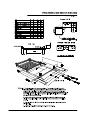
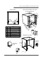
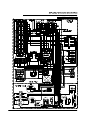
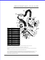
DRAIN PUMP KIT 0440031 - XP/AL3/AL8/PW1
400 90144 19/11/2013 REV 1-G
3
4
23
2
17
TO SELECTOR
SWITCH
14
10
16
15
22
20
17
9
21
17
8
2
17
1
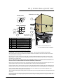
DRAIN PUMP KIT 0440031
ITEM
PART NUMBER
DESCRIPTION
1
600 30102
SWITCH C/RINSE ROLD SPCO
1
2
ASS16
HOSE CLAMP
4
3
600 30173
P CLIP
1
4
600 60105
HOSE DRAIN 2.5M
1
5
600 60102
DRAIN PUMP
1
6
88461
MS HX SS 304 M6 x 12
1
7
8566-1
WASHER SPRING SS 304 M6
1
8
600 90074
UD UHB25 HOSE BEND
1
9
38823
DRAIN PUMP UNION
1
10
38824
GASKET DRAIN PUMP UNION
1
11
400 900144
RETROFIT DIAGRAM
1
12
600 30032
WIRE 0.75 YELLOW/BROWN
0.7m
13
600 30016
WIRE 0.75 BLACK
1.5m
14
600 30015
WIRE 0.75 RED
0.5m
15
600 30033
WIRE 0.75 WHITE/BLUE
0.2m
16
600 30023
WIRE 0.75 BROWN
0.2m
17
H3560
TERMINAL RED SPADE
7
18
H4207
TERMINAL RED FLAT
2
19
600 30297
BUTTON WITH DRAIN SYMBOL
1
20
600 30081
BASE 2 POLE RELAY
1
21
600 30080
RELAY 2 POLE (240VAC)
22
REF
3M VHB TAPE
23
400 10021
ASSY DRAIN PUMP FILTER
19
13
QTY
TO POWER
18 TERMINAL
2
13
12
2
17
5
6
7
1
40mm
1
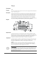
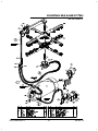
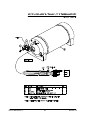
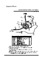
1. Pre-assemble the drain pump with the flexible outlet hose #4, the inlet hose #8, the drain pump union #9.
Secure the hoses with the supplied hose clamps #2.
2. Secure drain pump to base with M6 bolt #6 and the spring washer #7, provided in the kit.
3. Fit the drain union gasket #10 into the drain pump union #9. and screw the drain pump union #9 on to the drain waste of the
machine.
4. Secure drain outlet hose above the water level using P clip #3 supplied in the kit.
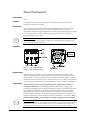
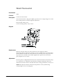
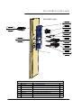
5. Cut out the right side hole below the wash temperature gauge in the control panel label (if see from the front). and fit the drain
switch #1. Fit the base and the relay #20 & 21 at the back of control panel using double-sided adhesive tape provided.
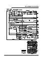
6. Wire the drain pump, the drain switch and the drain relay according to electrical diagrams, provided in service manual or
schematic diagram, supplied with the machine.
Service Manual XP-2
38
Revision 1C