1
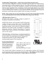
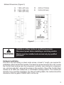
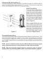
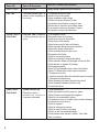
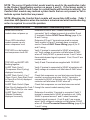
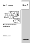
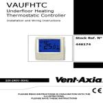
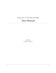
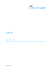
543-0032-00, 943-0032-00
User’s Manual
1
Comfort Alert™ Diagnostics – Faster Service And Improved Accuracy
The Comfort Alert diagnostics module is a breakthrough innovation for troubleshooting
heat pump and air conditioning system failures. The module installs easily in the electrical
box of the outdoor unit near the compressor contactor. By monitoring and analyzing
data from the Copeland Scroll® compressor and the thermostat demand, the module
can accurately detect the cause of electrical and system related failures without any
sensors. A flashing LED indicator communicates the ALERT code and guides the service
technician more quickly and accurately to the root cause of a problem.
NOTE: This module does not provide safety protection! The Comfort Alert module
is a monitoring device and cannot shut down the compressor directly.
LED Description (Figure 1)
POWER LED (Green): indicates voltage is present at
the power connection of the module.
ALERT LED (Yellow): communicates an abnormal system
condition through a unique flash code. The ALERT LED
will flash a number of times consecutively, pause and then
repeat the process. The number of consecutive flashes,
defined as the Flash Code, correlates to a particular
abnormal condition. Detailed descriptions of specific
ALERT Flash Codes are shown in two tables on pages 8
and 9 of this manual.
TRIP LED (Red): indicates there is a demand signal from
the thermostat but no current to the compressor is detected
by the module. The TRIP LED typically indicates the
compressor protector is open or may indicate
missing supply power to the compressor.
Product Specifications
Operating Temperature:
Storage Temperature:
Power Supply Range:
Power Requirement:
UL Restrictions:
-40° to 150° F (-40° to 65° C)
-40° to 175° F (-40° to 80° C)
18-30VAC, 48-62 Hz
1.5 VA nominal
Use only with Class 2 circuits.
Figure 1
UL File #SA8958
This Comfort Alert module is designed only for single-phase systems with Copeland
scroll compressors that have internal overload protection. The software in this Comfort
Alert module has been optimized for single stage scroll systems.
2
Module Dimensions (Figure 2):
A.
B.
C.
1.85 in (47 mm)
2.44 in (62 mm)
1.46 in (37 mm)
D.
E.
4.40 in (112mm)
2.44 in (62 mm)
Figure 2
Hazardous voltage inside air conditioning system.
Disconnect power before installing or servicing module.
WARNING
Module must be installed and serviced only by qualified
personnel.
Hardware Installation
Four #8 or #10 self drilling or sheet metal screws, at least ½” length, are required for
installation of the Comfort Alert module. The maximum screw torque is 20 in.-lbs. Locate
the Comfort Alert module near the compressor contactor (wire routing for compressor
run, common and start wires will be easier in this position). Mount the Comfort Alert
module so all LEDs are visible from a comfortable viewing position. The module will
operate in any mounting orientation. For ease of reading labels, the module should be
oriented so that the green POWER LED is at the top.
3
Compressor Wire Routing (Figure 3)
The scroll compressor’s run (R), common (C) and start (S) wires are routed through the
holes in the Comfort Alert module marked “R,” “C” and “S.” The common (C) wire need
not be routed through the module for it to operate properly.
24VAC Power Wiring
The Comfort Alert module requires
a constant nominal 24VAC power
supply. The wiring to the module’s
R and C terminals must be directly
from the indoor unit or thermostat.
The module cannot be powered by
the C terminal on a defrost board
or other control board without
experiencing nuisance alerts.
Refer to Figure 5.
Figure 3
When constant 24VAC (R wire)
is not present in the outdoor unit,
use one of the spare wires in the
thermostat cable to bring power to
the module. Connect the other end
of the spare wire to R at the indoor
unit or thermostat. Refer to wiring
schematic in Figure 4 and 5.
Thermostat Demand Wiring
The Comfort Alert module requires a thermostat demand signal to operate properly. The
thermostat demand signal input, labeled Y on the module, should always be connected
to the compressor contactor coil so that when the coil is energized, the demand signal
input is 24VAC. When the coil is not energized, the demand signal input should be less
than 0.5VAC.
NOTE: Factory installed modules may have different thermostat demand signal
wiring. Follow manufacturer’s wiring instructions when replacing module.
NOTE: After the thermostat demand signal is connected, verify Y is phased
properly with C by measuring 24VAC across Y and C when demand is present.
4
CC
HPCO
HTCO
R
L
Y1
L
Y1
LPCO
Y
Comfort Alert
Diagnostics
Module
543-0032-00
L
R
C
Indoor Unit
Terminal Block
C
C
R
Single Stage Indoor Thermostat
Figure 4 Air Conditioning Schematic
Schematic Abbrevation Descriptions
HTCO High Temperature Cut Out Switch
HPCO High Pressure Cut Out Switch
CC Compressor Contactor
LPCO Low Pressure Cut Out Switch
CC
HPCO
HTCO
LPCO
Y
Comfort Alert
Diagnostics
Module
543-0032-00
L
Defrost
Board
R
C
Indoor Unit
Terminal Block
C
C
R
R
L
Y1
L
Y1
Single Stage Indoor Thermostat
Figure 5 Heat Pump Schematic
5
L Terminal Wiring
The L connection is used to communicate Alert codes to compatible White-Rodgers
thermostats. The L terminal of the thermostat should be connected directly to the Comfort
Alert L terminal.
On select White-Rodgers thermostats, an icon on the thermostat display will flash at
the same rate as the Comfort Alert yellow Alert LED. An advanced option on these
thermostats is to lock out the compressor when certain Alert codes are detected indicating
impending compressor damage. Refer to White-Rodgers thermostat manuals for more
information.
6
Interpreting The Diagnostic LEDs
When an abnormal system condition occurs, the Comfort Alert module displays the
appropriate ALERT and/or TRIP LED. The yellow ALERT LED will flash a number of
times consecutively, pause and then repeat the process. To identify a Flash Code
number, count the number of consecutive flashes. Every time the module powers
up, the last ALERT Flash Code that occurred prior to shut down is displayed for one
minute.
Installation Verification
To verify the installation of Comfort Alert is correct, two functional tests can be performed.
Disconnect power from the compressor and force a thermostat call for cooling. The red
Trip LED should turn on indicating a compressor trip as long as 24VAC is measured at
the Y terminal. If the red LED does not function as described, refer to Table 1 to verify
the wiring.
Disconnect power from the compressor and 24VAC from Comfort Alert. Remove the
wire from the Y terminal of Comfort Alert, reapply 24VAC power to Comfort Alert and
reconnect power to the compressor. Force a thermostat call for cooling and when the
Compressor starts to run, the yellow Alert LED will begin flashing a Code 8 indicating
a Welded Contactor. Disconnect power from the compressor and 24VAC from Comfort
Alert. While Comfort Alert is off, reattach the wire to the Y terminal. Reapply power to
compressor and 24VAC to Comfort Alert, the yellow Alert LED will flash the previous
code 8 for 1 minute and then turn off. If the yellow LED does not function as described,
refer to Table 1 to verify the wiring.
Troubleshooting The Installation
Depending on the system configuration, some ALERT Flash codes may not be active.
The presence of safety switches affects how the system alerts are displayed by this
module. Refer to Figures 4 & 5 for safety switch wiring.
Resetting Alert Codes
Alert codes can be reset manually and automatically. The manual method to reset an Alert
code is to cycle the power to Comfort Alert off and on. For automatic reset, Comfort Alert
continues to monitor the compressor and system after an Alert is detected. If conditions
return to normal, the Alert code is turned off automatically.
Comfort Alert Part Numbers
OEM P/N
Service P/N
Copeland Scroll Compressor Application
543-0010-00
943-0010-00
Single Stage Air Conditioning
543-0012-00
943-0012-00
All Heat Pump and Two Stage A/C
543-0032-00
943-0032-00
Single Stage A/C & Heat Pump
543-0033-00
943-0033-00
Two Stage A/C & Heat Pump
7
8
Status LED
Status LED Description
Status LED Troubleshooting Information
Green “POWER”
Module has power
Supply voltage is present at module terminals
Red “TRIP”
Thermostat demand signal Y is
present, but the compressor is
not running
1.Compressor protector is open
•Check for high head pressure
•Check compressor supply voltage
2.Outdoor unit power disconnect is open
3.Compressor circuit breaker or fuse(s) is open
4.Broken wire or connector is not making contact
5.Low pressure switch open if present in system
6.Compressor contactor has failed open
Yellow “ALERT”
Flash Code 1
Long Run Time Compressor
is running extremely long run
cycles
1.Low refrigerant charge
2.Evaporator blower is not running
•Check blower relay coil and contacts
•Check blower motor capacitor
•Check blower motor for failure or blockage
•Check evaporator blower wiring and connectors
•Check indoor blower control board
•Check thermostat wiring for open circuit
3.Evaporator coil is frozen
•Check for low suction pressure
•Check for excessively low thermostat setting
•Check evaporator airflow (coil blockages or return air filter)
•Check ductwork or registers for blockage
4.Faulty metering device
•Check TXV bulb installation (size, location and contact)
•Check if TXV/fixed orifice is stuck closed or defective
5. Condenser coil is dirty
6. Liquid line restriction (filter drier blocked if present in system)
8. Thermostat is malfunctioning
•Check thermostat sub-base or wiring for short circuit
•Check thermostat installation (location, level)
9.Comfort Alert failure
Yellow “ALERT”
Flash Code 2
System Pressure Trip
Discharge or suction
pressure out of limits or
compressor overloaded
1. High head pressure
•Check high pressure switch if present in system
•Check if system is overcharged with refrigerant
•Check for non-condensable in system
2. Condenser coil poor air circulation (dirty, blocked, damaged)
3.Condenser fan is not running
•Check fan capacitor
•Check fan wiring and connectors
•Check fan motor for failure or blockage
4.Return air duct has substantial leakage
5.If low pressure switch present in system, check Flash
Code 1 information
Status LED
Status LED Description
Status LED Troubleshooting Information
Yellow “ALERT”
Flash Code 3
Short Cycling
Compressor is running
only briefly
1. Thermostat demand signal is intermittent
2. Time delay relay or control board defective
3. If high pressure switch present go to Flash Code 2 information
4. If low pressure switch present go to Flash Code 1 information
Yellow “ALERT”
Flash Code 4
Locked Rotor
1.Run capacitor has failed
2.Low line voltage (contact utility if voltage at disconnect is low)
•Check wiring connections
3.Excessive liquid refrigerant in compressor
4.Compressor bearings are seized
•Measure compressor oil level
Yellow “ALERT”
Flash Code 5
Open Circuit
1.Outdoor unit power disconnect is open
2.Compressor circuit breaker or fuse(s) is open
3.Compressor contactor has failed open
•Check compressor contactor wiring and connectors
•Check for compressor contactor failure (burned, pitted or open)
•Check wiring and connectors between supply and compressor
•Check for low pilot voltage at compressor contactor coil
4.High pressure switch is open and requires manual reset
5.Open circuit in compressor supply wiring or connections
6.Unusually long compressor protector reset time due to
extreme ambient temperature
7.Compressor windings are damaged
•Check compressor motor winding resistance
Yellow “ALERT”
Flash Code 6
Open Start Circuit
Current only in run circuit
1.Run capacitor has failed
2.Open circuit in compressor start wiring or connections
•Check wiring and connectors between supply and the
compressor “S” terminal
3.Compressor start winding is damaged
•Check compressor motor winding resistance
Yellow “ALERT”
Flash Code 7
Open Run Circuit
Current only in start circuit
1.Open circuit in compressor run wiring or connections
•Check wiring and connectors between supply and the
compressor “R” terminal
2.Compressor run winding is damaged
•Check compressor motor winding resistance
Yellow “ALERT”
Flash Code 8
Welded Contactor
Compressor always runs
1.Compressor contactor has failed closed
2.Thermostat demand signal not connected to module
Yellow “ALERT”
Flash Code 9
Low Voltage
Control circuit < 17VAC
1.Control circuit transformer is overloaded
2.Low line voltage (contact utility if voltage at disconnect is low)
•Check wiring connections
Flash Code number corresponds to a number of LED flashes, followed by a pause and then repeated.
TRIP and ALERT LEDs flashing at same time means control circuit voltage is too low for operation.
9
NOTE: The correct Comfort Alert model must be used for the application (refer
to the Product Specification section on pages 2 and 3). If the wrong model is
installed, the ALERT Flash Codes for system faults will function incorrectly: the
Comfort Alert module may indicate system faults that are not present or fail to
indicate system faults that are present.
NOTE: Miswiring the Comfort Alert module will cause false LED codes. Table 1
describes LED operation when the module is miswired and what troubleshooting
action is required to correct the problem.
Miswired Module Indication
Recommended Troubleshooting Action
Green LED is not on,
module does not power up
Determine if both R and C module terminals are
connected. Verify voltage is present at module’s R and
C terminals. Review 24VAC Power Wiring (page 4) for
R and C wiring.
Determine if R and Y terminals are wired in reverse.
Verify module’s R and C terminals have a constant
source. Review 24VAC Power Wiring (page 4) for R
and C wiring.
Green LED intermittent,
module powers up only
when compressor runs
TRIP LED is on but system
and compressor check OK
Verify Y terminal is connected to 24VAC at contactor
coil. Verify voltage at contactor coil falls below 0.5VAC
when off. Verify 24VAC is present across Y and C when
thermostat demand signal is present. If not, R and C are
reverse wired.
TRIP LED and ALERT LED
flashing together
ALERT Flash Code 3
(Compressor Short Cycling)
displayed incorrectly
ALERT Flash Code 5, 6 or 7
(Open Circuit, Open Start Circuit
or Open Run Circuit) displayed
incorrectly
ALERT Flash Code 6 (Open
Start Circuit) displayed for Code 7
(Open Run Circuit) or vice versa
ALERT Flash Code 8
(Welded Contactor)
displayed incorrectly
Verify R and C terminals are supplied with 19-28VAC.
Verify Y terminal is connected to 24VAC at contactor coil.
Verify voltage at contactor coil falls below 0.5VAC when
off.
Check that compressor run and start wires are through
module’s current sensing holes. Verify Y terminal is
connected to 24VAC at contactor coil. Verify voltage at
contactor coil falls below 0.5VAC when off.
Check that compressor run and start wires are routed
through the correct module sensing holes.
Determine if module’s Y terminal is connected. Verify Y
terminal is connected to 24VAC at contactor coil. Verify
24VAC is present across Y and C when thermostat
demand signal is present. If not, R and C are reverse
wired. Verify voltage at contactor coil falls below 0.5VAC
when off. ReviewThermostat Demand Wiring (page 4) for
Y and C wiring.
Table 1
10
Warranty Information
Copeland Corporation warrants its enclosed diagnostic module to be free from defects in
materials and workmanship under normal use for a period of one year from the date of
purchase or twenty months from manufacture whichever comes first. During this period,
Copeland Corporation will replace any defective diagnostic module without charge.
This warranty is valid for the original purchaser from the date of initial purchase and is
not transferable. Keep the original sales receipt. Proof of purchase is required to obtain
warranty replacement. Dealers or service centers selling this product do not have the
right to alter, modify or in any way change the terms and conditions of this warranty.
This warranty does not cover normal wear of parts or damage resulting from any of the
following: negligent use or misuse of the product, use on improper voltage or current,
use contrary to the operating instructions, disassembly, repair or alteration by anyone
other than Copeland Corporation. Further, the warranty does not cover acts of God,
such as fire, flood, hurricanes and tornadoes.
COPELAND CORPORATION MAKES NO IMPLIED WARRANTIES OF
MERCHANTABILITY OR FITNESS FOR PARTICULAR PURPOSE WITH RESPECT
TO THE COMFORT ALERT MODULE.
Copeland Corporation shall not be liable for any incidental or consequential damages
caused by the breach of any express or implied warranty. Some states, provinces,
or jurisdictions do not allow the exclusion or limitation of incidental or consequential
damages or limitations on how long an implied warranty lasts, so the above limitations
or exclusions may not apply to you. This warranty gives you specific legal rights, and
you may also have other rights that vary from state to state, or province to province.
Units under warranty and in need of repair should be returned to an authorized wholesaler
or original equipment manufacturer.
11
Patent 6, 615, 594 and Additional Patents Pending
Form No. 2005ECT-25 Issued 3/05
Emerson Climate Technologies is a service mark and a trademark
of Emerson Electric Co. Comfort Alert is a trademark of Copeland
Corporation. Printed in the U.S.A. © 2005 Copeland Corporation.
12