1
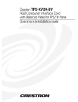
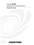
Crestron CPC-2000A Touchpanel with Dual Joysticks Contents Touchpanel with Dual Joysticks: CPC-2000A 1 Description................................................................................................................................. 1 Functional Description ................................................................................................ 1 Software ...................................................................................................................... 1 Physical Description.................................................................................................... 1 Leading Specifications............................................................................................................... 3 Setup .......................................................................................................................................... 4 Recommended Cleaning.............................................................................................. 4 Network Wiring........................................................................................................... 5 Hardware Hookup ....................................................................................................... 5 Identity Code ............................................................................................................... 6 Configuring the Touchpanel........................................................................................ 7 Programming ........................................................................................................................... 10 Reserved Join Numbers............................................................................................. 10 Sample Program ........................................................................................................ 11 Problem Solving ...................................................................................................................... 11 Troubleshooting ........................................................................................................ 11 Further Inquiries........................................................................................................ 13 Software License Agreement................................................................................................... 14 Return and Warranty Policies.................................................................................................. 16 Merchandise Returns / Repair Service ...................................................................... 16 CRESTRON Limited Warranty ................................................................................ 16 Operations Guide - DOC. 5801A Contents • i Crestron CPC-2000A Touchpanel with Dual Joysticks Touchpanel with Dual Joysticks: CPC-2000A Description Functional Description The CPC-2000A is a 5.7 inch (14.5 cm) passive matrix color LCD touchscreen control panel with dual joystick control and adjustable speed knobs for the remote control system (herein referred to as the control system). As part of the Crestron ProCam family which includes pan/tilt heads, a camera control network is formed. The network can accept up to 250 separate cameras - or other controlled devices - at distances up to 5000 feet without expansion modules. This unique camera control network also allows the option of additional or alternative controllers, such as Crestron touchpanels, PC-based control software, and button panel consolettes. When included in a camera control network with proper programming, the CPC-2000A permits control of camera pan/tilt and lens zoom/focus with speed adjustments. Presets that store the pan/tilt/zoom/focus positions are allowed. Software The CPC-2000A has one 256-color palette. Therefore, all custom colors are mapped to the nearest color in that palette, such that colors from the custom color dialog box may not be exactly represented. If the precise shade is not immediately achieved, the solution is to experiment with a slightly different color from the custom color dialog box in VT Pro-e. VisionTools™ Pro-e (VT Pro-e), a Windows-based design software, permits the creation of unlimited control screen variations incorporating two and threedimensional graphics and text. A set of pages which make up a project can be designed for each CPC-2000A application. Each page contains objects such as custom control graphics, two and three-dimensional buttons, sliders, and digital readouts which allow the user to interface with the control system. The project is uploaded to the touchpanel and programmed into the flash PROM. The touchpanel uses the programmed project until another set is uploaded from the PC. The PC may be disconnected from the rack or panel, except during reprogramming. VT Pro-e also allows users the option to generate projects destined for web browsers rather than for physical touchpanels. For additional software information, consult the VT Pro-e help file. Physical Description The 5.7 inch (14.5 cm) touch sensitive viewing screen is located on the large angled portion of the top face of the CPC-2000A. The touchscreen is identical to the Operations Guide - DOC. 5801A Touchpanel with Dual Joysticks: CPC-2000A • 1 Touchpanel with Dual Joysticks Crestron CPC-2000A Crestron CT-1600 with respect to programming and configuration. The electronic hardware is housed in a black metal enclosure with silk-screened labels, shown below. Four speed adjustment knobs are located below the touchsceen area. Two joysticks are located on the horizontally level area of the top face. A RJ-type network connector is available from the back panel of the unit. There are four rubber feet on the base of the unit for stability and to prevent slippage. CPC-2000A Physical Views 9.00 in (22.86 cm) 4.09 in (10.40 cm) BACK PANEL TOP FACE SIDE VIEW 10.07 in (25.59 cm) Sensitivity Adjustment Knobs Four sensitivity adjustment knobs, located beneath the touchscreen, are used to regulate pan, tilt, focus, and zoom speeds. Turning the knobs clockwise maximizes 2 • Touchpanel with Dual Joysticks: CPC-2000A Operations Guide - DOC. 5801A Crestron CPC-2000A Touchpanel with Dual Joysticks the speed. Speed can be adjusted while using the joysticks. The knobs are panel mounted single-turn potentiometers. Joysticks Two 2-axis, spring centering joysticks, located beneath the sensitivity adjustment knobs, are used to control pan, tilt, focus, and zoom movement of a network camera/lens assembly. Vertical movement of the right-most joystick (when viewing the touchscreen) tilts the head. Horizontal movement of the right-most joystick pans the head. Vertical movement of the left-most joystick zooms the lens. Horizontal movement of the left-most joystick focuses the lens. Network Connector This 6-pin, 6-position RJ11 modular jack, located on the back panel of the CPC-2000A, is used to receive power and to communicate with the control system. Use the cable assembly (supplied) to connect the CPC-2000A to the CN-RJ11 (supplied) and, in turn, connect the CN-RJ11 to the control system per the latest revision of the network interconnection diagram (Doc. 5411). If connecting the CPC-2000A to a CNX-series control system, the CN-RJ11 is not required. Make connections per the latest revision of the modular cable requirements (Doc. 5682). Leading Specifications The two tables, shown after this paragraph, provides a summary of leading specifications for the CPC-2000A and joystick particulars. Dimensions and weight are rounded to the nearest hundredth unit. Leading Specifications of the CPC-2000A SPECIFICATION Power Requirements Default Network ID SIMPL™ Windows® CNX Operating System CNX Monitor CNMS, CNRACK, CNLCOMP Operating System ST-CP Operating System ST-CP Monitor VisionTools™ Pro Crestron Database Memory Dimensions Weight (without CN-RJ11) * DETAILS 12 Watts, 24 VDC 0.5 Amp 03 (touchpanel) & 30H (joystick) Version 1.22 or later* Version 5.01.09x or later Version 2.00 or later Version 3.16.08 or later Version 4.00.29 or later Version 1.29 or later Version 1.2.1 or later* Version 11.7.209 or later* 768 Kbytes flash memory for display Height: 4.09 in (10.40 cm) Width: 9.00 in (22.86 cm) Depth: 10.07 in (25.59 cm) 3.60 lb (1.63 Kg) The latest software versions can be obtained from the Downloads page (SIMPLWIN, TOUCHPNL, and CRESDB Libraries) on the Crestron website (www.crestron.com). New users are required to register in order to obtain access to the FTP site. NOTE: In order to have CPC-2000A available from the Device Library when programming in SIMPL Windows, use the latest version of SIMPL Windows available from Crestron’s website or use an earlier version with library update file smwlib58.exe and library update document smwlib58.txt or later. These update files are available from the Downloads page (SIMPLWIN Library) of Crestron’s website. Operations Guide - DOC. 5801A Touchpanel with Dual Joysticks: CPC-2000A • 3 Touchpanel with Dual Joysticks Crestron CPC-2000A Leading Specifications of the CPC-2000A (Continued) SPECIFICATION View Screen Dimensions View Screen Resolution View Screen Display View Screen Illumination View Screen Touch Screen DETAILS Height: 3.50 in (8.89 cm) Width: 4.70 in (11.94 cm) 320 x 240 pixels Passive Matrix Color LCD Edgelit Fluorescent Resistive Membrane Leading Specifications of the CPC-2000A Joysticks SPECIFICATION Number of Axes Mounting Bezel Centering DETAILS 2-Axis Rubber Boot Seal Spring Centering As of the date of manufacture, the CPC-2000A has been tested and found to comply with specifications for CE marking. NOTE: This device complies with part 15 of the FCC rules. Operation is subject to the following two conditions: (1) these devices may not cause harmful interference, and (2) these devices must accept any interference received, including interference that may cause undesired operation. Setup Recommended Cleaning Keep the surface of the touchscreen free of dirt, dust, or other materials that could degrade optical properties. Long term contact with abrasive materials can scratch the surface which may detrimentally affect image quality. For best cleaning results, use a clean, damp, non-abrasive cloth with any commercially available non-ammonia glass cleaner. The surrounding plastic enclosure may not provide a complete water-tight seal, therefore, apply cleaning solution to the cloth rather than the surface of the touchscreen. Wipe touchscreen clean and avoid ingress of moisture beneath panels. 4 • Touchpanel with Dual Joysticks: CPC-2000A Operations Guide - DOC. 5801A Crestron CPC-2000A Touchpanel with Dual Joysticks Network Wiring NOTE: This section only applies to those applications using 4-wire Cresnet wiring. When calculating the wire gauge for a particular network run, the length of the run and the power factor of each network unit to be connected must be taken into consideration. If network units are to be daisy-chained on the run, the power factor of each network unit to be daisy-chained must be added together to determine the power factor of the entire chain. If the network unit is a home-run from a Crestron system power supply network port, the power factor of that network unit is the power factor of the entire run. The length of the run in feet and the power factor of the run should be used in the resistance equation, shown below, to calculate the value on the right side of the equation. Resistance Equation R < 40,000 L x PF Where: R = Resistance (refer to table below) L = Length of run (or chain) in feet PF = Power factor of entire run (or chain) The required wire gauge should be chosen such that the resistance value is less than the value calculated in the resistance equation. Refer to the table below. Wire Gauge Values RESISTANCE (R) WIRE GAUGE 4 16 6 18 10 20 15 22 13 Doubled CAT5 8.7 Tripled CAT5 NOTE: All Cresnet wiring must consist of two twisted-pairs. One twisted pair is the +24V conductor and the GND conductor and the other twisted pair is the Y conductor and the Z conductor. NOTE: When daisy-chaining Cresnet units, strip the ends of the wires carefully to avoid nicking the conductors. Twist together the ends of the wires that share a pin on the network connector, and tin the twisted connection. Apply solder only to the ends of the twisted wires. Avoid tinning too far up the wires or the end becomes brittle. Insert the tinned connection into the Cresnet connector and tighten the retaining screw. Repeat the procedure for the other three conductors. Hardware Hookup WARNING: To avoid shock hazard and possible damage to the unit, do not use touchpanel in rain or expose it to unnecessary moisture. NOTE: The CN-RJ11 is not necessary if the CPC-2000A is connected directly to a CNX-series control system. NOTE: Before making any connections, review the latest revisions of the network interconnection drawing (Doc. 5411) and the network modular cable requirements Operations Guide - DOC. 5801A Touchpanel with Dual Joysticks: CPC-2000A • 5 Touchpanel with Dual Joysticks Crestron CPC-2000A (Doc. 5682). Pinout notations are provided on these documents. The wiring documents can be obtained from the Downloads page (CABLES and MANUALS Libraries) of the Crestron website (www.crestron.com). Search for the CRESNET.PDF and MODULAR.PDF files. Refer to the hookup diagram below for proper connections of the CPC-2000A to the control system. Other than making the power connection last, complete the connection in any order. Control System Hookup Connections for the CPC-2000A NOTE: UNITS IN THIS ILLUSTRATION ARE NOT DRAWN TO SCALE. CRESTRON CN-RJ11 BACK PANEL VIEW OF CPC-2000A CONTROL SYSTEM NOTE: THIS CONNECTION IS ONLY REQUIRED WHEN LOADING YOUR VT PRO-E PROJECT TO THE CPC-2000A OR WHEN SETTING THE NET ID OF THE JOYSTICK. PC SERIAL PORT Identity Code Each device and user interface within the network requires a unique identity code (NET ID). These codes are recognized by a two-digit hexadecimal number from 03 to FE. The NET ID of the unit must match an identity code specified in the SIMPL Windows program. The CPC-2000A possesses two distinct identity codes; one code is for the touchpanel and the other is for the sensitivity adjustment knobs and joysticks which are treated as a network device. The NET ID of the touchpanel component is set to 03. Refer to “Interface Menu” on page 9 for instructions on setting the touchpanel component of the unit’s identity code. For the knob/joystick component, the NET ID has been factory set to 30H, but may be changed from the PC via VT Pro-e or SIMPL Windows. The method for changing the unit’s NET ID is identical regardless of the software chosen. Attach the CPC-2000A to the control system (verify that the software is running) and complete the following steps to change the NET ID. 1. Disconnect all network devices from the control system, except for the one CPC-2000A that needs to have its NET ID changed. 6 • Touchpanel with Dual Joysticks: CPC-2000A Operations Guide - DOC. 5801A Crestron CPC-2000A Touchpanel with Dual Joysticks 2. Select Tools | ViewPort to open the “Crestron Performance Viewport” dialog box. 3. Select Functions | Set Network ID. The software checks the baud rate and then opens the “Set Network ID” dialog box. 4. Notice the list of current network devices in the dialog box. Highlight the CPC-2000A. 5. The NET ID of the CPC-2000A (default is 30H) appears in the box below the list. Use the scroll arrow to assign another NET ID. 6. When the newly assigned NET ID appears, select the Set ID button to initiate the change. 7. The software responds with a successful message to confirm the new NET ID. 8. To verify this procedure, select Diagnostics | Report Network Devices. Confirm that the CPC-2000A has a new NET ID code. 9. Reconnect other network devices that were disconnected in step 1. Configuring the Touchpanel Main Menu It may be necessary to make adjustments or configure the touchpanel due to utilization or a particular appearance chosen by the user. To configure the CPC-2000A, it may be necessary to access a series of setup screens prior to viewing run-time screens that are loaded into the touchpanel for normal operation. The Main Menu for configuring the touchpanel appears when a finger is held to the touchscreen as power is applied. Remove your finger when the message “SETUP MODE” appears on the touchscreen. Holding a finger to the touchscreen for five seconds after the “SETUP MODE” message is displayed sets the brightness to high and the contrast to a safe value. Upon entering SETUP MODE, the Main Menu, shown to the left of this paragraph, displays four buttons: TOUCH SCREEN CALIBRATION, DIAGNOSTICS, SETUP, and SAVE SETUP AND RUN PROGRAM. Calibration Menu Calibration Menu Calibration of the touchscreen is required if the active touch area of a button does not coincide with the button’s image. Select the TOUCH SCREEN CALIBRATION button on the Main Menu to display the Calibration Menu, shown to the left of this paragraph. The Calibration Menu offers the choice to initiate calibration with the Perform Calibration button or return to the previous screen with the Return to Main Menu button. Choose an option by touching the correct button. When touching the screen, be as accurate as possible. If you proceed to calibrate the touchpanel, the screen prompts you with the message “Touch Screen Calibration Menu” nearly centered on the display. Another message, “Touch Upper Left Corner”, appears in the upper left corner. Touch the corner of the screen to initiate calibration. Another message, “Touch Lower Right Corner”, appears in the lower right corner. Touch the corner of the screen to return to the Main Menu and terminate calibration. Operations Guide - DOC. 5801A Touchpanel with Dual Joysticks: CPC-2000A • 7 Touchpanel with Dual Joysticks Crestron CPC-2000A Diagnostics Menu Diagnostics Menu The DIAGNOSTICS button from the Main Menu should only be used under supervision from a Crestron technical support representative during telephone support. The options available from the Diagnostics Menu, shown to the left of this paragraph, are numeric in nature and its interpretation is beyond the scope of this manual. Select the RETURN button, located at the lower right corner, to get back to the Main Menu. Setup Menu Setup Menu To obtain the Setup Menu, shown to the left of this paragraph, select the SETUP button from the Main Menu. Many options for setting touchpanel parameters are available from the Setup Menu and are explained in the following paragraphs. After setup parameters have been set, select the RETURN button, located at the lower right corner of the Setup Menu. Brightness Screen brightness may need to be altered because of ambient light conditions or personal preference. Three brightness buttons, BRT LOW, BRT MED, and BRT HI, located in the lower left row of the Setup Menu may be selected to increment the backlight setting. Contrast Screen contrast may need to be altered because of ambient light conditions, panel temperature, or personal reference. Two contrast buttons, CONT << and CONT >>, located on the left side, center row of the Setup Menu may be held down for continuous and smooth adjustment of the screen. Timeout Menu NOTE: Display backlight requires warm-up time. A display reaches 80% of its final level in five minutes and full brightness in 20 minutes. Timeout Menu The touchpanel display hardware life can be lengthened by turning off the backlight when the touchpanel is inactive. The MANAGE POWER button is located in the top left corner of the Setup Menu. Selection of this button changes the touchpanel display to reveal the Timeout Menu, shown to the left of this paragraph. BACKLIGHT TIMEOUT is displayed on the Timeout Menu. This setting turns the backlight off when the touchpanel is inactive for a specified time frame (shown in minutes). When the touchpanel is activated, the last screen to be displayed reappears. A two minute BACKLIGHT TIMEOUT is shown in the illustration. Minutes can vary from 0 to 120, where 0 disables the timeout. DOWN and UP buttons decrease and increase the timeout, respectively. After the timeout parameter has been set, touch the SAVE TIMEOUT button in the lower left corner of the screen to save the new settings. Touch the RETURN button, located in the lower right corner of the screen, to display the Setup Menu. Panel Tracking Panel tracking is a useful communication feature between touchpanels when more than one touchpanel exists on the network. Panel tracking is enabled when the PANEL TRACKING button, located on the right side of the center row of the Setup Menu, is selected. Selection is indicated with red text. When enabled, a given touchpanel maintains communication in such a way that a page change to any 8 • Touchpanel with Dual Joysticks: CPC-2000A Operations Guide - DOC. 5801A Crestron CPC-2000A Touchpanel with Dual Joysticks touchpanel on the network forces the same page change to all enabled touchpanels. Panel tracking is disabled when the PANEL TRACKING button is deselected. When disabled a given touchpanel does not respond to page changes made to other touchpanels on the network. Panel tracking is factory set with the PANEL TRACKING button deselected. Interface Menu Interface Menu The touchpanel communicates with a control system to activate other controls or to display feedback from components within the system. The communication interface must be correctly specified or communication does not occur. To set communication parameters select the INTERFACE button located centrally in the top row of the Setup Menu and display the Interface Menu, shown to the left of this paragraph. The Cresnet network identity number (NET ID) is displayed in the top left corner of the Interface Menu. NET ID is the two-digit hexadecimal number represented by ## in the figure for illustrative purposes. The hexadecimal number can range from 03 to FE and must correspond to the NET ID set in the SIMPL Windows program. Matching NET IDs between touchpanel and the program is required if data is to be successfully transferred or new touchpanel screens are to be loaded. NET ID is factory set to 03. Two side-by-side buttons adjacent to the hexadecimal display, < CRESNET ID and CRESNET ID >, decrease and increase the NET ID by one, respectively. The touchpanel usually communicates with a control system. Occasionally the touchpanel can be used in local demo mode where it merely displays various menus, but does not communicate with the control system. In local mode, the directory buttons change pages, but buttons requiring feedback do not work. Two centrally located buttons on the Interface Menu, CRESNET II and LOCAL, determine communication mode. Select LOCAL to set the touchpanel into demo mode and CRESNET II for normal control system communication mode. Text within the selected button changes color from black to red. Communication mode is factory set to CRESNET II. Two side-by-side buttons, RS-232 ON and RS-232 OFF, are centrally located on the Interface Menu. Text within the selected button changes color from black to red. Since there is no RS-232 port on the unit, verify that the RS-232 OFF button is selected. Furthermore, there is no need to use the RS232 SETTINGS button on the Interface Menu. Sound Menu Sound Menu The SOUND button, located at the top right corner of the Setup Menu, is used to display the Sound Menu, shown to the left of this paragraph. Use this screen to activate audible key clicks. This feature is a useful feedback tool. Confirmation of a button press on a touchpanel is acknowledged by an audible click assuming this feature is enabled. To enable this feature, verify that the KEYCLICK ON button is active (red). An active KEYCLICK OFF button disables the feature. Volume of the audible click is controlled with the VOLUME UP and VOLUME DOWN buttons. The unit is factory set with the sound on. Return Select the RETURN button, located at the lower right corner of the Setup Menu, after setup parameters have been set. Operations Guide - DOC. 5801A Touchpanel with Dual Joysticks: CPC-2000A • 9 Touchpanel with Dual Joysticks Crestron CPC-2000A Save Setup and Run Program The SAVE SETUP AND RUN PROGRAM button, located at the upper right corner of the Main Menu, saves all of the setup information to EPROM and displays the main page that has been programmed into your system. Programming The touchpanel component of the CPC-2000A is programmed as if it were a CT-1600 touchpanel. Therefore, when designing projects in an earlier version of VT Pro for use with the CPC-2000A, choose CT-1600 as the touchpanel target type. The latest version of VT Pro-e has CPC-2000A available as a target type. However, instructions for screen design are not presented in this guide; refer to VT Pro-e’s help file for assistance. The software also provides a step-by-step tutorial to fully acquaint the novice programmer. Once the project has been developed, it must be uploaded to the touchpanel. Refer to the hook-up diagram illustrated in RESISTANCE (R) WIRE GAUGE “ 4 16 6 18 10 20 15 22 13 Doubled CAT5 8.7 Tripled CAT5 NOTE: All Cresnet wiring must consist of two twisted-pairs. One twisted pair is the +24V conductor and the GND conductor and the other twisted pair is the Y conductor and the Z conductor. NOTE: When daisy-chaining Cresnet units, strip the ends of the wires carefully to avoid nicking the conductors. Twist together the ends of the wires that share a pin on the network connector, and tin the twisted connection. Apply solder only to the ends of the twisted wires. Avoid tinning too far up the wires or the end becomes brittle. Insert the tinned connection into the Cresnet connector and tighten the retaining screw. Repeat the procedure for the other three conductors. Hardware Hookup” on page 5 for proper connections when uploading the project. NOTE: Do not choose CPC-2000 from the Device Library when programming in SIMPL Windows. It represents an older product that incorporates the CT-1500. Instead choose CPC-2000A which incorporates the CT-1600 or choose CT-1600. In order to have CPC-2000A available from the Device Library when programming in SIMPL Windows, use the latest version of SIMPL Windows available from Crestron’s website or use an earlier version with library update file smwlib58.exe and library update document smwlib58.txt or later. These update files are available from the Downloads page (SIMPLWIN Library) of Crestron’s website. Reserved Join Numbers A reserved join number is a feature of the software that enables a designer to create a button on a page that either calls up the Setup Menu, ramps brightness, etc. The table shown after this paragraph provides a list of reserved join numbers available within the software for the CPC-2000A. 10 • Touchpanel with Dual Joysticks: CPC-2000A Operations Guide - DOC. 5801A Crestron CPC-2000A Touchpanel with Dual Joysticks Reserved Join Numbers for the CPC-2000A JOIN NUMBER FUNCTION VALUE 1016 1017 1018 1019 1035 Backlight Brightness Brightness Brightness Call up Setup Menu Off Low Medium High N/A Sample Program NOTE: Rather than presenting an illustrative example with SIMPL Window screen shots in this documentation, please refer to the zipped file available from the Crestron website. Due to the unique combination of a user interface and additional network device properties of the CPC-2000, a complete sample program is available from the Downloads page (EXAMPLES Library) on the Crestron website (www.crestron.com). The file CPC2000A.ZIP contains the VT Pro-e touchpanel files, SIMPL Windows files, and all supporting files such as macros. There is also a text file that explains all that is to be known about the sample programs provided. The program works in conjunction with selected CPC-CAMIs in a sample application where the CPC-2000A controls the pan/tilt head and a lens with focus/zoom capabilities. The application provides 16 presets that store the pan/tilt/focus/zoom positions. Via the sample program, the speed of the pan/tilt/focus/zoom axes are finely controlled by the sensitivity adjustment knobs of the CPC-2000A. Turning the knob counterclockwise decreases the speed of axis movement. To increase the speed, turn the knob clockwise. If the knob is turned counterclockwise to a stop, the axis does not move. A page from a touchpanel project in VT Pro-e is also provided to allow an operator to set up the camera and flip any of the axes. Sometimes when a system is installed, an axis may appear backwards (i.e., the camera tilts up when it should tilt down). This project page provides easy setup without having to change wiring or modify the program. The flip states are preserved through power downs of the system. This project page is accessed by touching and holding the upper left camera icon for five seconds. A brightness and contrast control page for the touchpanel component of the CPC-2000A is accessed by touching the upper right camera icon. Problem Solving Troubleshooting The table below and on the next page provides corrective action for possible trouble situations, If further assistance is required, please contact a Crestron customer service representative. Operations Guide - DOC. 5801A Touchpanel with Dual Joysticks: CPC-2000A • 11 Touchpanel with Dual Joysticks Crestron CPC-2000A CPC-2000A Troubleshooting POSSIBLE CAUSE(S) TROUBLE Project can not be uploaded to the touchpanel. Wrong screens appear on touchpanel. CORRECTIVE ACTION Touchpanel has powered down. NET ID on touchpanel is improperly set. Power panel with power pack when programming and uploading project. Verify that NET ID match. Refer to "Interface Menu" in this Operations Guide and NET ID parameters assigned in the software program. Communication error; Verify upload preferences is set to the COM port being used to communicate to the control incorrect COM port system. specified. Verify upload preferences specifies RACK (not the PANEL) as target of the upload. Panel type error; NET Verify that panel NET ID matches the NET ID set in the VT Pro-e program. Refer to "Interface ID for panel and VT Pro-e project NET ID Menu" in this Operations Guide. do not match. Screens were not Upload screens as described in the help files uploaded. found in VT Pro-e. CPC-2000A Troubleshooting (Continued) TROUBLE POSSIBLE CAUSE(S) CORRECTIVE ACTION Touchpanel No power to the Confirm that network power is supplied. does not touchpanel. function. CPC-2000A is Select Perform Calibration button from incorrectly calibrated. Calibration Menu to enter "calibration mode". If the Perform Calibration button cannot be reached, complete the following steps. Remove network power. Reapply power while holding finger to the touchscreen for approximately 10 seconds. During this short period, the words "SETUP MODE" appear as does the Opening Screen. Touch the Opening Screen and select the Perform Calibration button from the Calibration Menu to enter "calibration mode". Poll the network (F4 in either VT Pro-e or SIMPL Touchpanel is not communicating to the Windows) to verify communication. control system. Touch screen to reactivate. Touchpanel Standby or power down timeout has display is elapsed. dark. Power is not applied Verify that power is properly applied and all to the touchpanel. connections are made. Touchpanel Screen brightness or Hold a finger to the touchscreen for more than 10 contrast is improperly seconds as power is applied. The display sets display is the brightness and contrast to a safe value. dark or too set. light. Touchpanel Compressed graphics If there are no memory problems, decompressed graphics decrease the drawing time of panel exhibits slow take time to pages. decompress. operation. 12 • Touchpanel with Dual Joysticks: CPC-2000A Operations Guide - DOC. 5801A Crestron CPC-2000A Touchpanel with Dual Joysticks Further Inquiries If after reviewing this Operations Guide for the CPC-2000A, you can not locate specific information, please take advantage of Crestron’s award winning customer service team by calling: • In the US and Canada, call Crestron’s corporate headquarters at 1-888-CRESTRON [1-888-273-7876] or 1-201-767-3400. • In Europe, call Crestron International at +32-15-50-99-50. • In Asia, call Crestron Asia at +852-2341-2016. • In Latin America, call Crestron Latin America at +5255-5093-2160. • In Australia, call Crestron Pacific at +613-9480-2999. For local support from exclusive Crestron factory-trained personnel in New Zealand call Amber Technologies at +649-410-8382. Operations Guide - DOC. 5801A Touchpanel with Dual Joysticks: CPC-2000A • 13 Touchpanel with Dual Joysticks Crestron CPC-2000A Software License Agreement This License Agreement (“Agreement”) is a legal contract between you (either an individual or a single business entity) and Crestron Electronics, Inc. (“Crestron”) for software referenced in this guide, which includes computer software and, as applicable, associated media, printed materials, and “online” or electronic documentation (the “Software”). BY INSTALLING, COPYING, OR OTHERWISE USING THE SOFTWARE, YOU REPRESENT THAT YOU ARE AN AUTHORIZED DEALER OF CRESTRON PRODUCTS OR A CRESTRON AUTHORIZED INDEPENDENT PROGRAMMER AND YOU AGREE TO BE BOUND BY THE TERMS OF THIS AGREEMENT. IF YOU DO NOT AGREE TO THE TERMS OF THIS AGREEMENT, DO NOT INSTALL OR USE THE SOFTWARE. IF YOU HAVE PAID A FEE FOR THIS LICENSE AND DO NOT ACCEPT THE TERMS OF THIS AGREEMENT, CRESTRON WILL REFUND THE FEE TO YOU PROVIDED YOU (1) CLICK THE DO NOT ACCEPT BUTTON, (2) DO NOT INSTALL THE SOFTWARE AND (3) RETURN ALL SOFTWARE, MEDIA AND OTHER DOCUMENTATION AND MATERIALS PROVIDED WITH THE SOFTWARE TO CRESTRON AT: CRESTRON ELECTRONICS, INC., 15 VOLVO DRIVE, ROCKLEIGH, NEW JERSEY 07647, WITHIN 30 DAYS OF PAYMENT. LICENSE TERMS Crestron hereby grants You and You accept a nonexclusive, nontransferable license to use the Software (a) in machine readable object code together with the related explanatory written materials provided by Creston (b) on a central processing unit (“CPU”) owned or leased or otherwise controlled exclusively by You, and (c) only as authorized in this Agreement and the related explanatory files and written materials provided by Crestron. If this software requires payment for a license, you may make one backup copy of the Software, provided Your backup copy is not installed or used on any CPU. You may not transfer the rights of this Agreement to a backup copy unless the installed copy of the Software is destroyed or otherwise inoperable and You transfer all rights in the Software. You may not transfer the license granted pursuant to this Agreement or assign this Agreement without the express written consent of Crestron. If this software requires payment for a license, the total number of CPU’s on which all versions of the Software are installed may not exceed one per license fee (1) and no concurrent, server or network use of the Software (including any permitted back-up copies) is permitted, including but not limited to using the Software (a) either directly or through commands, data or instructions from or to another computer (b) for local, campus or wide area network, internet or web hosting services; or (c) pursuant to any rental, sharing or “service bureau” arrangement. The Software is designed as a software development and customization tool. As such Crestron cannot and does not guarantee any results of use of the Software or that the Software will operate error free and You acknowledge that any development that You perform using the Software or Host Application is done entirely at Your own risk. The Software is licensed and not sold. Crestron retains ownership of the Software and all copies of the Software and reserves all rights not expressly granted in writing. OTHER LIMITATIONS You must be an Authorized Dealer of Crestron products or a Crestron Authorized Independent Programmer to install or use the Software. If Your status as a Crestron Authorized Dealer or Crestron Authorized Independent Programmer is terminated, Your license is also terminated. You may not rent, lease, lend, sublicense, distribute or otherwise transfer or assign any interest in or to the Software. You may not reverse engineer, decompile, or disassemble the Software. You agree that the Software will not be shipped, transferred or exported into any country or used in any manner prohibited by the United States Export Administration Act or any other export laws, restrictions or regulations (“Export Laws”). By downloading or installing the Software You (a) are certifying that You are not a national of Cuba, Iran, Iraq, Libya, North Korea, Sudan, or Syria or any country to which the United States embargoes goods (b) are certifying that You are not otherwise prohibited from receiving the Software and (c) You agree to comply with the Export Laws. If any part of this Agreement is found void and unenforceable, it will not affect the validity of the balance of the Agreement, which shall remain valid and enforceable according to its terms. This Agreement may only be modified by a writing signed by an authorized officer of Crestron. Updates may be licensed to You by Crestron with additional or different terms. This is the entire agreement between Crestron and You relating to the Software and it supersedes any prior representations, discussions, undertakings, communications or advertising relating to the Software. The failure of either party to enforce any right or take any action in the event of a breach hereunder shall constitute a waiver unless expressly acknowledged and set forth in writing by the party alleged to have provided such waiver. 14 • Touchpanel with Dual Joysticks: CPC-2000A Operations Guide - DOC. 5801A Crestron CPC-2000A Touchpanel with Dual Joysticks If You are a business or organization, You agree that upon request from Crestron or its authorized agent, You will within thirty (30) days fully document and certify that use of any and all Software at the time of the request is in conformity with Your valid licenses from Crestron of its authorized agent. Without prejudice to any other rights, Crestron may terminate this Agreement immediately upon notice if you fail to comply with the terms and conditions of this Agreement. In such event, you must destroy all copies of the Software and all of its component parts. PROPRIETARY RIGHTS Copyright. All title and copyrights in and to the Software (including, without limitation, any images, photographs, animations, video, audio, music, text, and “applets” incorporated into the Software), the accompanying media and printed materials, and any copies of the Software are owned by Crestron or its suppliers. The Software is protected by copyright laws and international treaty provisions. Therefore, you must treat the Software like any other copyrighted material, subject to the provisions of this Agreement. Submissions. Should you decide to transmit to Crestron’s website by any means or by any media any materials or other information (including, without limitation, ideas, concepts or techniques for new or improved services and products), whether as information, feedback, data, questions, comments, suggestions or the like, you agree such submissions are unrestricted and shall be deemed non-confidential and you automatically grant Crestron and its assigns a non-exclusive, royalty-tree, worldwide, perpetual, irrevocable license, with the right to sublicense, to use, copy, transmit, distribute, create derivative works of, display and perform the same. Trademarks. CRESTRON and the Swirl Logo are registered trademarks of Crestron Electronics, Inc. You shall not remove or conceal any trademark or proprietary notice of Crestron from the Software including any back-up copy. GOVERNING LAW This Agreement shall be governed by the laws of the State of New Jersey, without regard to conflicts of laws principles. Any disputes between the parties to the Agreement shall be brought in the state courts in Bergen County, New Jersey or the federal courts located in the District of New Jersey. The United Nations Convention on Contracts for the International Sale of Goods, shall not apply to this Agreement. CRESTRON LIMITED WARRANTY CRESTRON warrants that: (a) the Software will perform substantially in accordance with the published specifications for a period of ninety (90) days from the date of receipt, and (b) that any hardware accompanying the Software will be subject to its own limited warranty as stated in its accompanying written material. Crestron shall, at its option, repair or replace or refund the license fee for any Software found defective by Crestron if notified by you within the warranty period. The foregoing remedy shall be your exclusive remedy for any claim or loss arising from the Software. CRESTRON shall not be liable to honor warranty terms if the product has been used in any application other than that for which it was intended, or if it as been subjected to misuse, accidental damage, modification, or improper installation procedures. Furthermore, this warranty does not cover any product that has had the serial number or license code altered, defaced, improperly obtained, or removed. Notwithstanding any agreement to maintain or correct errors or defects Crestron, shall have no obligation to service or correct any error or defect that is not reproducible by Crestron or is deemed in Crestron’s reasonable discretion to have resulted from (1) accident; unusual stress; neglect; misuse; failure of electric power, operation of the Software with other media not meeting or not maintained in accordance with the manufacturer’s specifications; or causes other than ordinary use; (2) improper installation by anyone other than Crestron or its authorized agents of the Software that deviates from any operating procedures established by Crestron in the material and files provided to You by Crestron or its authorized agent; (3) use of the Software on unauthorized hardware; or (4) modification of, alteration of, or additions to the Software undertaken by persons other than Crestron or Crestron’s authorized agents. ANY LIABILITY OF CRESTRON FOR A DEFECTIVE COPY OF THE SOFTWARE WILL BE LIMITED EXCLUSIVELY TO REPAIR OR REPLACEMENT OF YOUR COPY OF THE SOFTWARE WITH ANOTHER COPY OR REFUND OF THE INITIAL LICENSE FEE CRESTRON RECEIVED FROM YOU FOR THE DEFECTIVE COPY OF THE PRODUCT. THIS WARRANTY SHALL BE THE SOLE AND EXCLUSIVE REMEDY TO YOU. IN NO EVENT SHALL CRESTRON BE LIABLE FOR INCIDENTAL, CONSEQUENTIAL, SPECIAL OR PUNITIVE DAMAGES OF ANY KIND (PROPERTY OR ECONOMIC DAMAGES INCLUSIVE), EVEN IF A CRESTRON REPRESENTATIVE HAS BEEN ADVISED OF THE POSSIBILITY OF SUCH DAMAGES OR OF ANY CLAIM BY ANY THIRD PARTY. CRESTRON MAKES NO WARRANTIES, EXPRESS OR IMPLIED, AS TO TITLE OR INFRINGEMENT OF THIRD-PARTY RIGHTS, MERCHANTABILITY OR FITNESS FOR ANY PARTICULAR PURPOSE, OR ANY OTHER WARRANTIES, NOR AUTHORIZES ANY OTHER PARTY TO OFFER ANY WARRANTIES, INCLUDING WARRANTIES OF MERCHANTABILITY FOR THIS PRODUCT. THIS WARRANTY STATEMENT SUPERSEDES ALL PREVIOUS WARRANTIES. Operations Guide - DOC. 5801A Touchpanel with Dual Joysticks: CPC-2000A • 15 Touchpanel with Dual Joysticks Crestron CPC-2000A Return and Warranty Policies Merchandise Returns / Repair Service 1. No merchandise may be returned for credit, exchange, or service without prior authorization from CRESTRON. To obtain warranty service for CRESTRON products, contact the factory and request an RMA (Return Merchandise Authorization) number. Enclose a note specifying the nature of the problem, name and phone number of contact person, RMA number, and return address. 2. Products may be returned for credit, exchange, or service with a CRESTRON Return Merchandise Authorization (RMA) number. Authorized returns must be shipped freight prepaid to CRESTRON, Cresskill, N.J., or its authorized subsidiaries, with RMA number clearly marked on the outside of all cartons. Shipments arriving freight collect or without an RMA number shall be subject to refusal. CRESTRON reserves the right in its sole and absolute discretion to charge a 15% restocking fee, plus shipping costs, on any products returned with an RMA. 3. Return freight charges following repair of items under warranty shall be paid by CRESTRON, shipping by standard ground carrier. In the event repairs are found to be nonwarranty, return freight costs shall be paid by the purchaser. CRESTRON Limited Warranty CRESTRON ELECTRONICS, Inc. warrants its products to be free from manufacturing defects in materials and workmanship under normal use for a period of three (3) years from the date of purchase from CRESTRON, with the following exceptions: disk drives and any other moving or rotating mechanical parts, pan/tilt heads and power supplies are covered for a period of one (1) year; touchscreen display and overlay components are covered for 90 days; batteries and incandescent lamps are not covered. This warranty extends to products purchased directly from CRESTRON or an authorized CRESTRON dealer. Purchasers should inquire of the dealer regarding the nature and extent of the dealer's warranty, if any. CRESTRON shall not be liable to honor the terms of this warranty if the product has been used in any application other than that for which it was intended, or if it has been subjected to misuse, accidental damage, modification, or improper installation procedures. Furthermore, this warranty does not cover any product that has had the serial number altered, defaced, or removed. This warranty shall be the sole and exclusive remedy to the original purchaser. In no event shall CRESTRON be liable for incidental or consequential damages of any kind (property or economic damages inclusive) arising from the sale or use of this equipment. CRESTRON is not liable for any claim made by a third party or made by the purchaser for a third party. CRESTRON shall, at its option, repair or replace any product found defective, without charge for parts or labor. Repaired or replaced equipment and parts supplied under this warranty shall be covered only by the unexpired portion of the warranty. Except as expressly set forth in this warranty, CRESTRON makes no other warranties, expressed or implied, nor authorizes any other party to offer any other party to offer any warranty, including any implied warranties of merchantability or fitness for a particular purpose. Any implied warranties that may be imposed by law are limited to the terms of this limited warranty. This warranty statement supercedes all previous warranties. Trademark Information All brand names, product names, and trademarks are the sole property of their respective owners. Windows is a registered trademark of Microsoft Corporation. Windows95/98/Me/XP and WindowsNT/2000 are trademarks of Microsoft Corporation. 16 • Touchpanel with Dual Joysticks: CPC-2000A Operations Guide - DOC. 5801A Crestron CPC-2000A Touchpanel with Dual Joysticks This page intentionally left blank. Operations Guide - DOC. 5801A Touchpanel with Dual Joysticks: CPC-2000A • 17 Touchpanel with Dual Joysticks Crestron CPC-2000A This page intentionally left blank. 18 • Touchpanel with Dual Joysticks: CPC-2000A Operations Guide - DOC. 5801A Crestron CPC-2000A Touchpanel with Dual Joysticks This page intentionally left blank. Operations Guide - DOC. 5801A Touchpanel with Dual Joysticks: CPC-2000A • 19