1
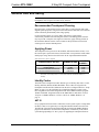
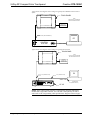
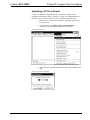
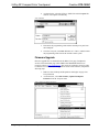
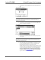
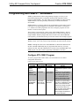
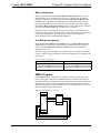
This document was prepared and written by the Technical Documentation department at:
Crestron Electronics, Inc.
15 Volvo Drive
Rockleigh, NJ 07647
1-888-CRESTRON
Crestron STX-1550C
2-Way RF Compact Color Touchpanel
Contents
2-Way RF Compact Color Touchpanel: STX-1550C
1
Description................................................................................................................................. 1
Functional Description ................................................................................................ 1
Physical Description.................................................................................................... 2
Software ...................................................................................................................... 2
Leading Specifications............................................................................................................... 3
General Use and Safety.............................................................................................................. 5
Recommended Touchpanel Cleaning .......................................................................... 5
Applying Power........................................................................................................... 5
Identity Codes.............................................................................................................. 5
Configuring the Touchpanel ...................................................................................................... 6
Touchscreen Calibration Menu ................................................................................... 6
Diagnostics Menu........................................................................................................ 7
Setup Menu.................................................................................................................. 7
Uploading and Upgrading.......................................................................................................... 9
Hookup and Preparation .............................................................................................. 9
Uploading a VT Pro-e Project ................................................................................... 13
Firmware Upgrade..................................................................................................... 14
Programming with SIMPL™ Windows® ............................................................................... 16
Configure STX-1550C Program................................................................................ 16
Example Program ...................................................................................................... 17
Reserved Join Numbers............................................................................................. 20
Problem Solving ...................................................................................................................... 21
Troubleshooting......................................................................................................... 21
Further Inquiries ........................................................................................................ 23
Future Updates .......................................................................................................... 23
Future Firmware Upgrades........................................................................................ 23
Appendix ................................................................................................................................. 24
Overview ................................................................................................................... 24
VT Pro-e Project........................................................................................................ 24
SIMPL Program ........................................................................................................ 25
Conclusion: How the Example Works ...................................................................... 26
Software License Agreement................................................................................................... 27
Return and Warranty Policies .................................................................................................. 29
Merchandise Returns / Repair Service ...................................................................... 29
CRESTRON Limited Warranty................................................................................. 29
Operations Guide - DOC. 5812A
Contents • i
Crestron STX-1550C
2-Way RF Compact Color Touchpanel
2-Way RF Compact Color
Touchpanel: STX-1550C
Description
Functional Description
The STX-1550C is a 2-way radio frequency (RF) compact color SmarTouch™
touchpanel that provides a user interface to a Crestron remote control system (herein
referred to as the Cresnet system). The touchpanel is a handheld, long range, RF,
2-way wireless transceiver that communicates through a RF gateway/transceiver,
STRFGWX (sold separately) to the Cresnet system. The 2-way communications
provide the control of the Cresnet devices and provide dynamic onscreen feedback
for real-time confirmation of commands. Up to 15 touchpanels can communicate
with one STRFGWX. The RF signals can travel from a minimum of three feet up to
a maximum of 50 - 75 feet. Additional range can be obtained by using multiple
STRFGWX units distributed throughout any particular area or installation. The
location and the antenna position of the STRFGWX are important factors in the RF
performance. The range of the touchpanel is also dependent on its placement and the
construction of the building in which it is used.
The STX-1550C touchpanel offers:
•
256 color display
•
Pop-up sub panels to reduce memory requirements, providing optimal
speed and performance
•
Multiple button, slider control, and icon configurations
•
Up to 999 functions and 96 screens
•
Imported photographs, drawings, and icons
•
Support for downloadable fonts - proportional and non-proportional
•
Foreign language text
Included with the STX-1550C is a Crestron High Performance Rechargeable Battery
Pack (ST-BTP) and a SmarTouch Docking Station (ST-DS) that docks the
touchpanel and/or recharges the ST-BTP. An external power pack (PW-1215 for
domestic use or PWI-1215 for international use) is also provided to power the
touchpanel and simultaneously trickle-charge the ST-BTP. Refer to the
documentation supplied with these items for descriptions and details.
Operations Guide - DOC. 5812A
2-Way RF Compact Color Touchpanel: STX-1550C • 1
2-Way RF Compact Color Touchpanel
Crestron STX-1550C
Physical Description
The touch-sensitive viewing screen is located on the top of each touchpanel. The
electronic hardware is housed in a high impact, black molded plastic enclosure, shown
below. Connectors to upload touchscreen projects via a personal computer (PC) and to
power the unit using the external power pack are located on the left and right sides of
the unit, respectively.
Physical Views of STX-1550C
5.01 in
(12.73 cm)
REFERENCE
3.33 in
(8.45 cm)
8.75 in
(22.23 cm)
5.70 in
(14.48 cm)
UPLOAD
CONNECTOR
CRESTRON
POWER
CONNECTOR
At the underside of the unit is the battery compartment that holds one ST-BTP.
Contacts for the ST-DS are through the ST-BTP. There are also four rubber feet on
the underside of the unit for stability and to prevent slippage.
Software
Have a comment about
Crestron software? Direct software
related suggestions and/or complaints
to Crestron via email
([email protected]).
Do not forward any queries to this
address. Instead, refer to “Further
Inquiries” on page 23 for assistance.
When part of a SmarTouch system, the STX-1550C is supported by the
VisionTools™ Pro-e (VT Pro-e) SmarTouch Wizard that automatically configures
the entire system and the touchpanel pages. VT Pro-e, a design and programming
Windows®-based software, permits the creation of unlimited control screen
variations incorporating two and three-dimensional graphics and text. A set of pages
which make up a project can be designed for each touchpanel application. Each page
contains objects such as custom control graphics, two and three-dimensional buttons,
sliders, and digital readouts which allow the user to interface with the Cresnet
system. The project is uploaded to the touchpanel and programmed into the flash
PROM. The touchpanel uses the programmed project until another set is uploaded
from the PC. The PC may be disconnected from the rack or panel except during
reprogramming. VT Pro-e also allows users the option to generate projects destined
for web browsers rather than for physical touchpanels.
For additional software information, refer to the help file provided with the software.
A copy of the software can be obtained from the What’s New page (VisionTools
Pro-e section) or Downloads page (TOUCHPNL Library) of Crestron’s website
(www.crestron.com). New users are required to register in order to obtain access to
the FTP site. A tutorial is provided as a guide for the novice programmer.
2 • 2-Way RF Compact Color Touchpanel: STX-1550C
Operations Guide - DOC. 5812A
Crestron STX-1550C
2-Way RF Compact Color Touchpanel
Leading Specifications
The table below provides a summary of leading specifications for the STX-1550C.
Dimensions and weight are rounded to the nearest hundredth unit.
Leading Specifications of the STX-1550C Touchpanel
SPECIFICATION
Power Source Options
ST-BTP
ST-DS
Domestic External Power Pack or
International External Power Pack
RF Communications
Operating Ranges
Minimum Distance
Maximum Distance Indoor
Maximum Distance Outdoor
Default NET ID
Default RF ID
SIMPL™ Windows®
VisionTools™ Pro-e (VT Pro-e)
Crestron Database
Firmware
Touchpanel
STRFGWX
CEN/CN-TVAV Update File
CNMSX-AV/Pro Update File
CNRACKX/-DP Update File
ST-CP Update File
Default Timeouts
Touchpanel Dimensions & Weight
Touchpanel Memory
View Screen Dimensions
Screen Viewing Angles
View Screen Resolution
View Screen Display
View Screen Illumination
View Screen Touchscreen
Operations Guide - DOC. 5812A
DETAILS
Rechargeable NiCad battery pack.
Docking station w/external power pack.
PW-1215 or equivalent.
PWI-1215 or equivalent.
2-Way, 418MHz, (Requires one STRFGWX
per 15 touchpanels.)
3 ft 1
50 to 75 ft 1
150 ft
03
01
Version 1.30.01 or later 2 with the addition of
smwlib70.exe and smwlib70.txt. 2
Version 2.1.8.2 or later 2 for SmarTouch
Wizard support or version 2.1.8 or later 2 for
regular support (use a CT-1600 model).
Version 12.1.4 or later 2 for SmarTouch
Wizard support or 12.1.3 later 2 for regular
support (use a CT-1600 model).
Version 5.077.0 or later. 3 & 4
Version 2.4.1 or later. 3 & 4
Version 51205V.UPZ or later. 5
Version 51020X.UPZ or later. 5
Version 51020W.UPZ or later. 5
Version 40104S.UPZ or later. 5
One (1) minute for standby, two (2) minutes
for powerdown.
Height: 5.70 in (14.48 cm)
Width: 8.75 in (22.23 cm)
Depth: 3.33 in (8.45 cm)
Weight: 1.56 lb (0.71 kg) 6
768Kb flash memory for display.
Height: 3.55 in (9.02 cm)
Width:
4.70 in (11.94 cm)
Diagonal: 5.70 in (14.50 cm)
+/-50o for X dir, +40/-50o for Y dir
320 x 240 pixels
Passive Matrix Color LCD
Backlit fluorescent
Resistive Membrane
2-Way RF Compact Color Touchpanel: STX-1550C • 3
2-Way RF Compact Color Touchpanel
1
Crestron STX-1550C
The location of the STRFGWX and the orientation of the antenna are important
factors in the RF performance. Locate the unit outside of any metal enclosures and
position the antenna horizontally, pointing straight out of the unit. Adjust the
antenna to achieve the best range. The range of the unit is also dependent on its
placement and the construction of the building in which it is used.
Installers can run multiple STRFGWX units which have built-in intelligence so that
if both (or several) gateways receive a button press from the touchpanel, only the
strongest signals produce an action in the control system. Crestron recommends that
the latest firmware be loaded into the touchpanel and STRFGWX. If the firmware of
the STX-1550C is upgraded, the associated STRFGWX(s) must also be upgraded at
the same time.
2
The latest software version can be obtained from the What’s New page (SIMPL
Windows, VisionTools Pro-e and Crestron Database sections) or Downloads page
(SIMPLWIN, VTPRO-E, and CRESDB Libraries) of Crestron’s website
(www.crestron.com). New users are required to register in order to obtain access to
the FTP site.
3
Touchpanels and STRFGWXs with later versions of firmware may include features
not mentioned in this guide. Newer versions of this guide can be obtained from the
Downloads page (MANUAL Library) of Crestron’s website.
4
Firmware upgrade files can be obtained from the What’s New page (Touchpanels
section) or the Downloads page (TOUCHPNL and UPGRADES Libraries) of
Crestron’s website. If the firmware of the STX-1550C is upgraded, the associated
STRFGWX(s) must also be upgraded at the same time.
5
CNX update files are required for either CNMSX-AV/Pro or CNRACKX/-DP.
Filenames for CNX update files have a UPZ extension and ST-CP files are in one
EXE or zipped UPZ file. All can be obtained from the What’s New page (Control
Systems Update Files section) or Downloads page (OPSYS Library) of Crestron’s
website.
6
The weight listed is for the touchpanel and does not include the ST-BTP, ST-DS, or
external power pack.
As of the date of manufacture, the unit has been tested and found to comply with
specifications for CE marking.
NOTE: Equipment has been tested and found to comply with the limits for a Class
B digital device, pursuant to part 15 of the FCC Rules. These limits are designed to
provide reasonable protection against harmful interference in a residential
installation. The equipment generates, uses and can radiate radio frequency energy
and, if not installed and used in accordance with the instructions, may cause harmful
interference to radio communications. However, there is no guarantee that
interference will not occur in a particular installation. If this equipment does cause
harmful interference to radio or television reception, which can be determined by
turning the equipment off and on, the user is encouraged to try to correct the
interference by one or more of the following measures:
Reorient or relocate the receiving antenna.
Increase the separation between the equipment and receiver.
Connect the equipment into an outlet on a circuit different from that to which the
receiver is connected.
Consult the dealer or an experienced radio/TV technician for help.
4 • 2-Way RF Compact Color Touchpanel: STX-1550C
Operations Guide - DOC. 5812A
Crestron STX-1550C
2-Way RF Compact Color Touchpanel
General Use and Safety
WARNING: To avoid shock hazard and possible damage to the unit, do not use
touchpanel in rain or expose it to unnecessary moisture.
Recommended Touchpanel Cleaning
Keep the surface of the touchscreen free of dirt, dust, or other materials that could
degrade optical properties. Long term contact with abrasive materials can scratch the
surface which may detrimentally affect image quality.
For best cleaning results, use a clean, damp, non-abrasive cloth with any
commercially available non-ammonia glass cleaner. Surrounding plastic enclosure
may not provide a complete water-tight seal. Therefore, apply cleaning solution to
the cloth rather than the surface of the touchscreen. Wipe touchscreen clean and
avoid ingress of moisture beneath panels.
Applying Power
The touchpanel can be powered via the ST-BTP, while docked in the ST-DS, or via
the external power pack. Each of these items has their own Operations Guides which
details proper usage. Refer to the table below for the required document number.
STX-1550C Power Source Options
*
POWER SOURCE OPTION
NOMENCLATURE
DOCUMENT
NUMBER *
Battery Pack
Docking Station
Domestic External Power Pack or
International External Power Pack
ST-BTP
ST-DS
PW-1215
PWI-1215
5746
5738
5762
5763
The latest revision may have a revision letter after the document number (i.e.,
5746A).
Identity Codes
The STX-1550C touchpanel uses three distinct types of identity (ID) codes: Cresnet
identity (NET ID), RF ID, and RF CHANNEL. These codes are assigned to the
touchpanel from the Interface Submenu when the unit is configured. Refer to “Setup
Menu” on page 7. For the touchpanel to be identified within the Cresnet system,
these assignments must match assignments made in the SIMPL Windows program.
The RF CHANNEL assignment made for the STRFGWX is made in the Crestron
Viewport via SIMPL Windows or VT Pro-e. Refer to “SIMPL Windows” on
page 13.
NET ID
Every equipment and user interface within the Cresnet system requires a unique NET
ID. These codes are recognized by a two-digit hexadecimal number from 03 to FE.
The NET ID of the unit must match the NET ID specified in the SIMPL Windows
program. The NET ID is used when the touchpanel is wired directly to the control
system during uploading a VT Pro-e project or upgrading the touchpanel firmware.
Operations Guide - DOC. 5812A
2-Way RF Compact Color Touchpanel: STX-1550C • 5
2-Way RF Compact Color Touchpanel
Crestron STX-1550C
RF CHANNEL
Each STX-1550C touchpanel communicating to the STRFGWX transceiver must
have a RF CHANNEL that matches the RF CHANNEL of the STRFGWX. There
are 16 possible RF CHANNELS ranging from 0 to F (hexadecimal number). The RF
CHANNEL of the touchpanel must match the RF CHANNEL assigned to the
STRFGWX.
NOTE: A single RF CHANNEL may be used by more than one STRFGWX when
multiple transceivers are used to expand the roaming capabilities of a touchpanel.
Refer to the latest revision of STRFGWX Operations Guide (Doc. 5811) for further
information. The latest version can be obtained from the Downloads page
(MANUAL Library) of Crestron’s website (www.crestron.com). New users are
required to register in order to obtain access to the FTP site.
RF ID
Every STX-1550C touchpanel communicating with a Cresnet control system via a
STRFGWX requires a unique RF ID to secure RF communications. There are 15
useable codes for multiple touchpanel(s) ranging from 01 to 0F (hexadecimal
number). The RF ID of the unit must match the RF ID specified in the SIMPL
Windows program.
NOTE: Do not set the RF ID to “0”; it is not supported in SIMPL Windows.
Configuring the Touchpanel
To configure the touchpanel, it is necessary to access a series of setup screens prior
to viewing run-time screens that are loaded into the touchpanel for normal operation.
The Main Menu for configuring the touchpanel appears when a finger is held to the
touchscreen as power is applied. Remove your finger when the message “SETUP
MODE” appears on the touchscreen. Holding a finger to the touchscreen for five
seconds after the “SETUP MODE” message is displayed sets the brightness to high.
Main Menu
Upon entering SETUP MODE, the Main Menu, shown to the left, displays four
buttons: TOUCH SCREEN CALIBRATION, DIAGNOSTICS, SETUP, and
SAVE SETUP AND RUN PROGRAM.
The Save Setup and Run Program button, located at the upper right corner of the
Main Menu, saves all of the setup information to EEPROM and displays the main
page that has been programmed into the system. The remaining buttons on the Main
Menu open other menus, which are discussed in subsequent paragraphs.
Calibration Menu
Touchscreen Calibration Menu
Calibration of the touchscreen is required if the active touch area of a button does
not coincide with the button’s image. Select the TOUCH SCREEN
CALIBRATION button on the Main Menu to display the Calibration Menu, shown
to the left. The Calibration Menu offers the choice to initiate calibration with the
Perform Calibration button or return to the previous screen with the Return to
Main Menu button. Choose an option by touching the correct button.
6 • 2-Way RF Compact Color Touchpanel: STX-1550C
Operations Guide - DOC. 5812A
Crestron STX-1550C
2-Way RF Compact Color Touchpanel
If you proceed to calibrate the touchpanel, the screen prompts you with the message
“Touch Screen Calibration Menu” nearly centered on the display. Another message,
“Touch Upper Left Corner”, appears in the upper left corner. Touch the corner of the
screen to initiate calibration. Another message, “Touch Lower Right Corner”,
appears in the lower right corner. Touch the corner of the screen to return to the
Main Menu and terminate calibration.
NOTE: When touching the screen during calibration, be as accurate as possible.
Diagnostics Menu
Diagnostics Menu
The DIAGNOSTICS button from the Main Menu should only be used under
supervision from a Crestron customer service representative during telephone
support. Most of the options available from the Diagnostics Menu, shown to the left,
are numeric in nature and their interpretation is beyond the scope of this guide.
Select the Return button to return to the Main Menu.
Setup Menu
Setup Menu
To obtain the Setup Menu, shown to the left, select the SETUP button from the
Main Menu. Many touchpanel options (i.e., contrast and brightness) are available
directly from the Setup Menu and are explained in the following paragraphs. Other
setup parameters (i.e., Manage Power, Interface, and Sound) use additional menus
and are detailed in subsequent paragraphs as well. After setup parameters have been
set, select the Return button to return to the Main Menu.
Contrast Buttons
Screen contrast may need to be altered because of ambient light conditions, panel
temperature, or personal preference. Two contrast buttons, Cont << and Cont >>, on
the Setup Menu may be held down for continuous adjustment of the screen.
Brightness Buttons
Screen brightness may need to be altered because of ambient light conditions or
personal preference. Three brightness buttons, BRT LOW, BRT MED, and BRT
HI, on the Setup Menu may be selected to assign the backlight setting.
Return Button
Select the RETURN button, located at the lower right corner of the Setup Menu,
after setup parameters have been set.
Timeout Screen
Manage Power Submenu
NOTE: Display backlight requires warm-up time. A display reaches 80% of its
final level in five minutes and full brightness in 20 minutes.
The touchpanel display hardware life can be lengthened by turning off the backlight
when the touchpanel is inactive. The MANAGE POWER button on the Setup
Menu reveals the Timeout screen, shown to the left. The length of touchpanel
inactivity can be specified to minimize power utilization.
Operations Guide - DOC. 5812A
2-Way RF Compact Color Touchpanel: STX-1550C • 7
2-Way RF Compact Color Touchpanel
Crestron STX-1550C
BACKLIGHT TIMEOUT is displayed on the Timeout screen. This setting turns
the backlight off when the touchpanel is inactive for the specified time (shown in
minutes). When the touchpanel is activated, the last screen to be displayed reappears.
A two minute BACKLIGHT TIMEOUT is shown in the diagram. Minutes can
vary from 0 to 120, where 0 disables the timeout. The DOWN and UP buttons
decrease and increase the timeout, respectively.
NOTE: Power Down Timeout should be set low to maximize battery life. However,
Power Down Timeout should be set greater than Standby Timeout. Otherwise, the
Standby Timeout is never reached.
NOTE: The purpose of the Power Down Timeout is to maximize battery life. If the
external power pack is attached to the touchpanel and plugged into an active AC
receptacle or if the touchpanel is resting in the docking station (ST-DS) and plugged
into an active AC receptacle, the panel does not power down when the power down
timeout is achieved. Standby timeout still functions.
After timeout parameters have been set, touch the SAVE TIMEOUTS button in the
lower left corner of the screen to save the new settings. Touch the RETURN button,
located in the bottom right corner of the screen, to display the Setup Menu.
Interface Screen
Interface Submenu
The touchpanel communicates with a control system to activate other controls or to
display feedback from components within the system. The communication interface
must be correctly specified or communication will not occur. To set communication
parameters select the INTERFACE button located in the upper left corner of the
Setup Menu to display the Interface Menu, shown to the left.
The NET ID is represented by # # for illustrative purposes on the Interface Menu.
NET ID is the two-digit hexadecimal number that can range from 03 to FE and must
correspond to the NET ID set in the Crestron Viewport via SIMPL Windows or VT
Pro-e software. Matching NET IDs between the STX-1550C touchpanel and a VT
Pro-e program is required if new touchpanel screens are to be loaded. Matching NET
IDs between touchpanels and a SIMPL Windows program is required if data is to be
successfully transferred. The NET ID of each STX-1550C is factory set to 03.
Two side-by-side buttons, < CRESNET ID and CRESNET ID >, decrease and
increase the NET ID by one, respectively.
The touchpanel usually communicates with a Cresnet system. Occasionally the
touchpanel can be used in a local demo mode where it merely displays various
menus, but does not communicate with the Cresnet system. In local mode, the
directory buttons change pages, but buttons requiring feedback do not work. Two
buttons on the Interface Menu, CRESNET II and LOCAL, determine
communication mode. Select CRESNET II for normal Cresnet communication
mode or LOCAL to set the touchpanel into demo mode. Text within the selected
button changes color from black to red and the communication mode is factory set to
CRESNET II.
8 • 2-Way RF Compact Color Touchpanel: STX-1550C
Operations Guide - DOC. 5812A
Crestron STX-1550C
RF Settings Screen
2-Way RF Compact Color Touchpanel
NOTE: Do not set the RF ID to “0”; it is not supported in SIMPL Windows.
The RF SETTINGS button opens the RF SETTINGS screen, shown to the left. The
RF ID is displayed in the RF SETTINGS screen. The RF ID must match the identity
code in the SIMPL Windows program and is identified by a hexadecimal number in
the range from 0 to F. In the diagram, the RF ID is shown with a setting of “01”. The
DOWN and UP buttons associated with the RF ID field decrease and increase the RF
ID by one, respectively.
NOTE: Due to network traffic, the STX-1550C may not respond to a network
upload. To compensate, access the setup screens (refer to “Configuring the
Touchpanel” on page 6) to provide exclusive upload communication between the
touchpanel and the control system.
The RF CHANNEL of the touchpanel
must be identical to the RF
CHANNEL of the STRFGWX(s) to
which it communicates. The same
channel may be used for more than
one STRFGWX when used to expand
the roaming capabilities of a
touchpanel within any particular
area(s) or installation.
The RF CHANNEL is displayed in the RF SETTINGS screen. The RF CHANNEL
is identified by a hexadecimal number in the range from 0 to F. In the diagram, the
RF CHANNEL is shown with a setting of “F”. The DOWN and UP buttons
associated with the RF ID field decrease and increase the RF ID by one,
respectively.
The TEST button should only be used under supervision from a Crestron customer
service representative during telephone support. The options available from the
TEST Menu are beyond the scope of this guide.
Select the RETURN button after interface parameters have been set.
Sound Screen
Sound Submenu
The SOUND button, located at the top right corner of the Setup Menu, is used to
display the Sound Menu, shown to the left. Use this screen to activate audible key
clicks. This feature is a useful feedback tool. Confirmation of a button press on a
touchpanel is acknowledged by an audible click assuming this feature is enabled. To
enable this feature, verify that the KEYCLICK ON button is active (red). An active
KEYCLICK OFF button disables the feature. Volume of the audible click is
controlled with the VOLUME UP and VOLUME DOWN buttons. The unit is
factory set with the sound on.
Uploading and Upgrading
To upload a VT Pro-e project or upgrade the firmware of the STX-1550C, a local PC
that contains the Crestron Viewport (available in SIMPL Windows or VT Pro-e) is
required. Refer to the following sections.
Hookup and Preparation
To prepare the STX-1550C for uploading or upgrading, refer to the figures shown on
the next page for typical connection diagrams. Complete the following steps
provided to ensure proper connection to the system.
NOTE: The components in the second figure on the next page are part of the
SmarTouch Programming Kit (ST-PK). If available, use these components.
Operations Guide - DOC. 5812A
2-Way RF Compact Color Touchpanel: STX-1550C • 9
2-Way RF Compact Color Touchpanel
Crestron STX-1550C
Typical Connection Diagram when Loading a Program from an MSX Generation Control
System
TOUCHPANEL
NOTE:
UNITS IN THIS ILLUSTRATION
ARE NOT DRAWN TO SCALE.
EXTERNAL
POWER PACK
(CRESTRON MODEL
OR EQUIVALENT)
CRESTRON
ST-CBL (SOLD SEPARATELY)
PC
COMPUTER
CONTROL
SYSTEM
NET
24 Y Z G
SERIAL PORT
Typical Connection Diagram when Loading a Program from the ST-CP
TOUCHPANEL
NOTE:
UNITS IN THIS ILLUSTRATION
ARE NOT DRAWN TO SCALE.
EXTERNAL
POWER PACK
(CRESTRON MODEL
OR EQUIVALENT)
CRESTRON
PC
15710 (PART OF ST-PK)
15717 (PART OF ST-PK)
SERIAL PORT
12VDC
.5A
NET
PC
COMA COMB
A
IR OUT
B
C
CRESTRON ELECTRONICS INC. N.J. 07626
D
USE ADAPTER
(PART OF ST-PK)
RF
ST-CP
NOTE: If the control system in use has a 4-pin network connector rather than a
modular (RJ11-type) NET connector, use a ST-CBL (sold separately) or make a
cable. Refer to the “Programming Cable Specifications” diagram on the next page.
10 • 2-Way RF Compact Color Touchpanel: STX-1550C
Operations Guide - DOC. 5812A
Crestron STX-1550C
2-Way RF Compact Color Touchpanel
Programming Cable Specifications
1.
Before making any connections to the touchpanel, verify that control
system is properly connected to the PC (using cable 15717 and adapter)
and powered on.
2.
Attach the stereo connector end of the programming cable, part number
15710, to the touchpanel.
3.
Attach the RJ11 connector end of the programming cable, part number
15710, to the connector labeled NET on the control system.
4.
Attach the appropriate external power pack or equivalent to touchpanel
and plug into outlet. At the PC, make sure that no programs accessing
the COM port of the PC are running.
5.
Start SIMPL Windows or VT Pro-e.
6.
From the SIMPL Windows or VT Pro-e menu bar, select Tools |
Viewport to open the Crestron Viewport.
NOTE: SIMPL Windows may open with an opening splash screen and may display
the “What do you want to do?” dialog box. If so, close the dialog box and continue.
7.
Operations Guide - DOC. 5812A
Refer to figure on the next page. From the Viewport menu, select
Setup | Communications settings (alternatively, depress Alt+D) to
open the Port Settings dialog box.
2-Way RF Compact Color Touchpanel: STX-1550C • 11
2-Way RF Compact Color Touchpanel
Crestron STX-1550C
Accessing the Port Settings Dialog Box
8.
Select the appropriate connection type. Verify that an available COM
port (COM 1 is shown below) is selected. Set the baud rate to 38400,
the parity to None, the data bits to Eight, and the stop bits to One.
Refer to the dialog box shown for the remaining settings and click the
OK button to save the settings and close the box.
Port Settings Dialog Box
9.
Proceed to “Uploading a VT Pro-e Project” on the next page or
“Firmware Upgrade” that begins on page 14 as appropriate.
12 • 2-Way RF Compact Color Touchpanel: STX-1550C
Operations Guide - DOC. 5812A
Crestron STX-1550C
2-Way RF Compact Color Touchpanel
Uploading a VT Pro-e Project
VT Pro-e is a Windows compatible software package for creating Crestron
touchpanel screen designs. Refer to “Software” on page 2 for additional details. To
upload a VT Pro-e project to the STX-1550C, complete the following steps.
1.
Make sure that “Hookup and Preparation” that begins on page 9 has
been performed.
2.
As shown below, select File Transfer | Send Touchpanel
(alternatively, depress Alt+T) from the Viewport menu.
Select Send Touchpanel
3.
As shown below, select the NET ID of the STX-1550C and then click
OK.
“Select Network ID” Dialog Box
Operations Guide - DOC. 5812A
2-Way RF Compact Color Touchpanel: STX-1550C • 13
2-Way RF Compact Color Touchpanel
4.
Crestron STX-1550C
As shown below, select the VT Pro-e (HEX) file and click Open. The
transfer will complete automatically.
Select HEX File
5.
Disconnect the programming cable and the external power pack from
the touchpanel.
6.
Close the Viewport, exit SIMPL Windows or VT Pro-e, and disconnect
the programming cable from the PC and the control system.
Firmware Upgrade
Firmware upgrade files are obtained from the What’s New page (Touchpanels
section) or the Downloads page (TOUCHPNL and UPGRADES Libraries) of
Crestron’s website (www.crestron.com). New users are required to register in order
to obtain access to the FTP site. To upgrade the STX-1550C firmware, complete the
following steps.
1.
Make sure that “Hookup and Preparation” that begins on page 9 has
been performed.
2.
As shown below, select File Transfer | Update Touchpanel
Firmware from the Viewport menu.
Select Update Touchpanel Firmware
14 • 2-Way RF Compact Color Touchpanel: STX-1550C
Operations Guide - DOC. 5812A
Crestron STX-1550C
2-Way RF Compact Color Touchpanel
3.
As shown below, select the NET ID of the STX-1550C and then click
OK.
“Select Network ID” Dialog Box
NOTE: Firmware upgrades for touchpanels contain two files, xc[version]a file and
xc[version]b file. When selecting a firmware file, select the a file which will
automatically execute the b file.
4.
As shown below, select the firmware (CSF) file and click Open. The
transfer will complete automatically.
Select CSF File
5.
Disconnect the programming cable and the external power pack from
the touchpanel.
NOTE: When the firmware of the STX-1550C is upgraded, the associated
STRFGWX(s) must also be upgraded. The units will not function properly if not
upgraded with compatible firmware.
6.
If the STRFGWX firmware upgrade HAS been completed, close the
Viewport, exit SIMPL Windows or VT Pro-e, and disconnect the
programming cable from the PC and the control system.
If NOT completed, perform the STRFGWX firmware upgrade utilizing
the firmware (UPG) file included with the download. Refer to the latest
revision of the Operations Guide (Doc. 5811) for the STRFGWX for
the firmware upgrade procedure. The latest version of the Operations
Guide can be obtained from the Downloads page (MANUAL Library)
of Crestron’s website (www.crestron.com). New users are required to
register in order to obtain access to the FTP site.
Operations Guide - DOC. 5812A
2-Way RF Compact Color Touchpanel: STX-1550C • 15
2-Way RF Compact Color Touchpanel
Crestron STX-1550C
Programming with SIMPL™ Windows®
SIMPL (Symbol Intensive Master Programming Language) is an easy-to-use
programming language that is completely integrated and compatible with all
Crestron system hardware. The objects that are used in SIMPL are called symbols.
SIMPL Windows offers drag and drop functionality in a familiar Windows®
environment.
SIMPL Windows is Crestron's software for programming Crestron control systems.
It provides a well-designed graphical environment with a number of workspaces
(i.e., windows) in which a programmer can select, configure, program, test, and
monitor a Crestron control system.
The next three sections describe a STX-1550C within SIMPL Windows. The first
section provides initial configuration information, the second section describes an
example SIMPL Windows program that utilizes a STX-1550C and a STRFGWX
(sold separately), and the third section provides the location of the example program.
NOTE: The following descriptions assume that the reader has knowledge of SIMPL
Windows. If not, refer to the extensive help information provided with the software.
NOTE: Although the STX-1550C and STRFGWX use RF formats different from
an STX-1600 and CNRFGWX, they are programmed the same way. You may
substitute an STX-1600 and CNRFGWX for an STX-1550C and STRFGWX in the
SMW program. The units cannot be physically substituted for each other.
Configure STX-1550C Program
To create a program with a STX-1550C, refer to the table below for initial
configuration information.
Configure STX-1550C Program
SYMBOL
FOLDER
SYMBOL
REQUIRED
DROP
WHERE
ADDITIONAL
SETUP
Device Library, Desired control System Views Refer to the documentation
system
supplied with the specific control
Control
system.
Systems
System Views, CHANGE NET ID (OPTIONAL) Device Library, STRFGWX
Cresnet Units Double-click on STRFGWX (or
Wireless
single-click then right mouseReceivers (RF)
click) on STRFGWX. Select
Configure. Select NET ID then
select desired hexidecimal ID.
Device Library, STX-1550C
System Views, CHANGE RF ID (OPTIONAL) (also used for STRFGWX
Single-click on STRFGWX. In the
Touchpanels
STX-1550CW)
System Views Detail Window,
(Wireless)
double-click (or single-click then
right mouse-click, select Configure) on name of STX-1550C in
STRF Address text window.
Select Configure. Select RF ID
then select desired ID.
16 • 2-Way RF Compact Color Touchpanel: STX-1550C
Operations Guide - DOC. 5812A
Crestron STX-1550C
2-Way RF Compact Color Touchpanel
Example Program
The STX-1550C or STX-1550CW touchpanel (sold separately) communicates to a
STRFGWX that resides on the Cresnet system. The program is available from the
Downloads page (EXAMPLES Library) of Crestron’s website (www.crestron.com).
Search for STX1550C.SMW. New users are required to register in order to obtain
access to the FTP site.
How the Example Program Works
The example STX-1550C SIMPL program is shown below in block diagram form.
(The SIMPL Windows symbol for the STRFGWX is not shown.) For this example,
the touchpanel in a volume control application where UP and DOWN presses ramp a
slider to a volume/tone control module (ST-VC), with a time interval of five seconds.
It also shows digital (signals A), analog (signals B), and serial (signal MSG$)
feedback to the panel. When the touchpanel buttons are pressed, the buttons are
highlighted and the bargraph on the touchpanel moves up or down. When MUTE is
pressed, Channel A of the ST-VC is muted and the text “MUTED” is sent to the
touchpanel. When the ST-VC is unmuted, a blank space is sent to the touchpanel.
Block Diagram of STX-1550C Program
How to Create the Example Program
Configuration Manager
Use the Configuration Manager workspace (Project | Configure System) in SIMPL
Windows to select and configure all the devices that need to be included into the
system. For this example, add a STRFGWX to the system then drop a STX-1550C
onto the STRFGWX. Verify the NET ID as shown on the next page.
CAUTION: The STX-1550C, SIMPL program, and the STRFGWX must be set to
the same NET ID. If changing the default NET ID, do NOT set the NET ID of the
STRFGWX to 1B or the unit will have to be returned to the factory.
Operations Guide - DOC. 5812A
2-Way RF Compact Color Touchpanel: STX-1550C • 17
2-Way RF Compact Color Touchpanel
Crestron STX-1550C
System View of STRFGWX NET ID Assignment in SIMPL Windows’ Configuration Manager
When the STX-1550C is dropped onto the STRFGWX, the first available RF ID
default address (01 as shown below) is automatically assigned. Verify or drag to
reassign the address in the Detail System View.
“STRF Address” Window
Next, add a ST-VC to the system and verify the NET ID as shown below.
System View of ST-VC NET ID Assignment in SIMPL Windows’ Configuration Manager
Programming Manager
Use the Programming Manager workspace (Project | Program System) in SIMPL
Windows to select symbols and assign their respective signals. For this example, a
STX-1550C touchpanel and ST-VC symbol were added automatically when the
devices were added to the system in the Configuration Manager workspace. Expand
the Network Modules folder and double-click on the STRFGWX and then on the
touchpanel for a detail view (alternatively CTRL+D or drag and drop into Detail
View). Assign digital, analog, and serial signals to the touchpanel as shown on the
next page.
18 • 2-Way RF Compact Color Touchpanel: STX-1550C
Operations Guide - DOC. 5812A
Crestron STX-1550C
2-Way RF Compact Color Touchpanel
Detail View of STX-1550C Digital Signals in SIMPL Windows’ Programming Manager
Detail View of STX-1550C Analog Signals in SIMPL Windows’ Programming Manager
Detail View of STX-1550C Serial Signals in SIMPL Windows’ Programming Manager
From the expanded Network Modules folder, double-click on the ST-VC
(alternatively CTRL+D or drag and drop into Detail View). Assign signals as shown
on the next page.
Detail View of ST-VC in SIMPL Windows’ Programming Manager
Operations Guide - DOC. 5812A
2-Way RF Compact Color Touchpanel: STX-1550C • 19
2-Way RF Compact Color Touchpanel
Crestron STX-1550C
Expand the Logic folder to display a number of symbols integrated into this
program. View each of the four symbols in detail view (alternatively CTRL+D or
drag and drop into Detail View). Assign signals as shown below.
Detail View of an Analog Ramp (S-1) in SIMPL Windows’ Programming Manager
Detail View of a Toggle (S-2) in SIMPL Windows’ Programming Manager
Detail View of Serial Sends (S-3 and S-4) in SIMPL Windows’ Programming Manager
Reserved Join Numbers
A reserved join number is a feature of the software that enables a designer to create a
button on a touchpanel page that either calls up the Preferences Menu, ramps
contrast, adjusts brightness, etc. These numbers also allow the control system to
trigger touchpanel functions (i.e., adjust brightness). The table shown on the next
page provides a list of reserved join numbers available within the software.
20 • 2-Way RF Compact Color Touchpanel: STX-1550C
Operations Guide - DOC. 5812A
Crestron STX-1550C
2-Way RF Compact Color Touchpanel
Reserve Join Numbers for STX-1550C
JOIN NUMBER
FUNCTION
VALUE
1015
1016
1017
1018
1019
1023
1024
1035
1036
1120 - 1123
Power
Stand by
Brightness
Brightness
Brightness
Contrast
Contrast
Reboots the System
Discharges ST-BTP
Digital Battery
Bargraph
Keyclick Volume
Keyclick Volume
Keyclick
Keyclick
Update Request
Out of Range *
Off
On
Low
Medium
High
Up
Down
N/A
N/A
Gauge Bottom (1120) to
Gauge Top (1123)
Up
Down
On
Off
N/A
N/A
1160
1161
1172
1173
1210
1213
*
Touchpanel RF channel no longer communicating with STRFGWX.
Problem Solving
Troubleshooting
The table below and continued on the next page provides corrective action for
possible trouble situations. If further assistance is required, please contact a Crestron
customer service representative.
STX-1550C Troubleshooting
TROUBLE
Project can
not be
uploaded to
touchpanel.
Project can
not be
uploaded:
1. Screen is
blank.
2. Checking
communications error.
Screens are
wrong.
Operations Guide - DOC. 5812A
POSSIBLE
CAUSE(S)
CORRECTIVE ACTION
Touchpanel has
powered down.
NET ID on touchpanel
is improperly set.
Power touchpanel with power pack when
programming and uploading project.
Verify that NET IDs match. Refer to the
Interface Submenu of "Setup Menu" that
begins on page 7 for details and NET ID
parameters assigned in the program.
Touchpanel is in
standby or powered
down.
Incorrect COM port
specified.
Touch the touchpanel to display a screen.
Verify that the panel has power supplied to it,
either battery or power pack.
Verify upload preferences is set to COM port
being used.
Verify upload preferences specifies RACK
(not the PANEL) as target of the upload.
Upload screens as described in the help files
found in VT Pro-e.
Screens were not
uploaded.
2-Way RF Compact Color Touchpanel: STX-1550C • 21
2-Way RF Compact Color Touchpanel
Crestron STX-1550C
STX-1550C Troubleshooting (continued)
TROUBLE
Touchpanel
exhibits slow
operation.
Touchpanel
does not
function.
POSSIBLE
CAUSE(S)
Compressed graphics
take time to
decompress.
No power to the
touchpanel.
Touchpanel is not
calibrated.
Touchpanel is not
communicating to the
control system.
Touchpanel Screen brightness or
display is too contrast is improperly
set.
dark or too
light.
Touchpanel RF signal may have
been lost.
graphics
garbled.
Touchpanel Touchpanel is out of
operation
range.
appears
unreliable.
Touchpanel
display is
blank.
Touchpanel
does not
function and
SIG LED on
STRFGWX
illuminates,
but Rx or Tx
LEDs do not.
CORRECTIVE ACTION
If there are no memory problems,
decompressed graphics decrease the
drawing time of panel pages.
Confirm that battery is installed or power
pack is attached.
Select the Calibration button from the
Preferences and Settings Menu to enter
"calibration mode". If the Calibration button
cannot be reached, complete these steps.
1. Remove power (battery and/or power
pack).
2. Reapply power while holding finger to the
touchscreen for approximately 10
(During this short period, the words
"SETUP MODE" appear as does the
Opening Screen.)
3. Touch the Opening Screen and select the
Calibration button from the Preferences
and Settings Menu to enter "calibration
mode".
Poll the network (F4 in either VT Pro-e or
SIMPL Windows) to verify communication.
Hold a finger to the touchscreen for more
than 10 seconds as power is applied. The
display sets the brightness and contrast to a
safe value.
Press "Update Request" button (designed
into users screen via VT Pro-e) to
resynchronize logic with control system.
Position touchpanel to within operating
range. Refer to "Leading Specifications" on
page 3 for details.
Use reserved join number 1213 in SIMPL
program to indicate when touchpanel
becomes out of range.
Install an additional STRFGWX near the
area of use to accommodate roaming.
Standby or power down Touch the screen to reactivate the
timeout has elapsed.
touchpanel.
Power is not applied to Verify that power is properly applied and all
the touchpanel.
connections are made.
Touchpanel RF ID is
Verify that RF IDs match. Refer to the
not set to match the RF Interface Submenu of "Setup Menu" that
ID assigned in the
begins on page 7 for details and RF ID
control system
parameters assigned in the program.
program.
22 • 2-Way RF Compact Color Touchpanel: STX-1550C
Operations Guide - DOC. 5812A
Crestron STX-1550C
2-Way RF Compact Color Touchpanel
Further Inquiries
If after reviewing this Operations Guide, you cannot locate specific information or have
questions, please take advantage of Crestron's award winning customer service team by
calling:
•
In the US and Canada, call Crestron’s corporate headquarters at
1-888-CRESTRON [1-888-273-7876] or 1-201-767-3400.
•
In Europe, call Crestron International at +32-15-50-99-50.
•
In Asia, call Crestron Asia at +852-2341-2016.
•
In Latin America, call Crestron Latin America at +5255-5093-2160.
•
In Australia, call Crestron Pacific at +613-9480-2999.
For local support from exclusive Crestron factory-trained personnel in New Zealand
call Amber Technologies at +649-410-8382.
Future Updates
As Crestron improves functions, adds new features, and extends the capabilities of the
STX-1550C, additional information and programming examples may be made available
as manual updates. These updates are solely electronic and serve as intermediary
supplements prior to the release of a complete technical documentation revision.
The Downloads page of the Crestron website (www.crestron.com) directs the reader to
the location and description of each update. Check the site periodically for update
availability and its subjective value.
Future Firmware Upgrades
As Crestron improves functions, adds new features, and extends the capabilities of the
STX-1550C, firmware upgrades may be made available. The upgrade files can be
obtained from the What’s New page (Touchpanels section) or the Downloads page
(TOUCHPNL and UPGRADES Libraries) of Crestron’s website. If the firmware of the
STX-1550C is upgraded, the associated STRFGWX(s) must also be upgraded.
Operations Guide - DOC. 5812A
2-Way RF Compact Color Touchpanel: STX-1550C • 23
2-Way RF Compact Color Touchpanel
Crestron STX-1550C
Appendix
The purpose of this Appendix is to provide a programming solution for those that
prefer the last screen to be displayed when the touchpanel turns on after encountering
a POWER DOWN TIMEOUT. Stated simply, an INTERLOCK symbol needs to be
incorporated so that the control system flips to the last page rather than the page
marked as first. The information in this Appendix is not meant for everyone; only
those who wish to adopt this feature.
Overview
This Appendix offers a simple example of a control system that has three devices to
control: TV, VCR, and projector. As such, the VT Pro-e project includes three pages,
one for each device. Particular settings must be made on each device page to ensure
proper functionality. To support the goal of having the last page appear, the program
needs to be adjusted via SIMPL Windows. This Appendix provides a SIMPL block
diagram and description to characterize the details of the adjustment.
VT Pro-e Project
NOTE: The control logic for these devices is omitted for the sake of clarity.
NOTE: It is assumed that the reader has a working knowledge of VT Pro-e. If any
of the terms in this discussion are unfamiliar, please review VT Pro-e’s on-line help
contents.
The VT Pro-e project in this example contains three device pages: TV, VCR, and
PROJECTOR, shown below.
Three Device Pages in the VT Pro-e Project
24 • 2-Way RF Compact Color Touchpanel: STX-1550C
Operations Guide - DOC. 5812A
Crestron STX-1550C
2-Way RF Compact Color Touchpanel
Button Assignment
In this system, the buttons labeled Press Here for VCR Control on the TV and
PROJECTOR pages are assigned a page flip to the VCR page and command the
projector to switch to its first video input. The buttons labeled Press Here for TV
Control on the VCR and PROJECTOR pages are assigned a page flip to the TV
page and command the projector to switch to its second video input. The buttons
labeled Press Here for Projector Control on the TV and VCR pages are assigned a
page flip to the PROJECTOR page. No other action is assigned.
All buttons on the device pages that cause page flips must be joined. This setting
permits the control system to keep track of every page flip and determine which page
is currently being displayed. That information is useful if the last page to be
displayed appears after a POWER DOWN TIMEOUT.
Join Number Assignment
In this example, Press Here for TV Control (Join # 6) and Press Here for VCR
Control (Join # 9) already have joined numbers assigned because they perform a
function. Only Press Here for Projector Control requires a new join number
assignment (Join # 22).
Each device page that is a destination of a page flip must be assigned a join number.
For this example, the page join numbers shown in the table below are assigned to the
device pages.
Page Join Number Assignments
DEVICE PAGE NAME
PAGE JOIN NUMBER
PROJECTOR
23
VCR
24
TV
25
SIMPL Program
In the SIMPL program, a signal must be assigned to Join # 22, so that the system
knows when a page is flipped to the PROJECTOR page. The name PROJ-FLIP is
assigned and placed on the button press side. There is no reason to have feedback on
the button since it flips the page immediately. For this example, assume Join # 6 is
assigned the signal name of TV-FLIP and Join # 9 has the signal name of VCR-FLIP.
Refer to the block diagram shown below.
SIMPL Block Diagram for the Example
STTW
RF ID: 0A
press6
press9
press22
INTERLOCK
TV-FLIP-F
TV-FLIP
VCR-FLIP-F
VCR-FLIP
PROJ-FLIP-F
PROJ-FLIP
S-1
fb23
fb24
fb25
STRFGWX
NET ID:03
Operations Guide - DOC. 5812A
2-Way RF Compact Color Touchpanel: STX-1550C • 25
2-Way RF Compact Color Touchpanel
Crestron STX-1550C
These three signal names should drive an INTERLOCK symbol so that the system
can “remember” which page was shown last on the touchpanel. The outputs of the
INTERLOCK are assigned unique names: TV-FLIP-F, VCR-FLIP-F, and
PROJ-FLIP-F.
Finally, the corresponding feedback signals from the INTERLOCK must match the
appropriate page join number. For this example, the page join numbers shown in the
table below correlate to the INTERLOCK output signals.
Feedback Signal Name with Join Number Assignments
FEEDBACK SIGNAL NAME
JOIN NUMBER
PROJ-FLIP-F
23
VCR-FLIP-F
24
TV-FLIP-F
25
Conclusion: How the Example Works
NOTE: Since the control system is controlling the page flips on the touchpanel, the
page flip setting on the buttons shown on the device pages can be removed via VT
Pro-e.
To illustrate how the example works, consider the following actions taken by the
user operating a STX touchpanel.
1.
While viewing the TV page of the VT Pro-e project on the touchpanel,
the user touches the Press Here for Projector Control button.
2.
Join # 22 feedback is activated which forces PROJ-FLIP to logic “1”.
3.
The INTERLOCK symbol outputs PROJ-FLIP-F as logic “1”; all other
outputs from the symbol are logic “0”.
4.
Join # 23 feedback is activated which forces the touchpanel to flip to
the PROJECTOR page of the project.
5.
Let the POWER DOWN TIMEOUT period expire so that the
touchpanel turns off (or turn off the unit) while the PROJECTOR page
is displayed.
6.
When the touchpanel is reactivated, the control system provides the
current state of all the analog and digital feedback signals. A logic “1”
for Join # 23 is one of the signals resynced and therefore, the
touchpanel flips to the PROJECTOR page rather than the page marked
as first.
26 • 2-Way RF Compact Color Touchpanel: STX-1550C
Operations Guide - DOC. 5812A
Crestron STX-1550C
2-Way RF Compact Color Touchpanel
Software License Agreement
This License Agreement (“Agreement”) is a legal contract between you (either an individual or a single business entity) and
Crestron Electronics, Inc. (“Crestron”) for software referenced in this guide, which includes computer software and, as applicable,
associated media, printed materials, and “online” or electronic documentation (the “Software”).
BY INSTALLING, COPYING, OR OTHERWISE USING THE SOFTWARE, YOU REPRESENT THAT YOU ARE AN
AUTHORIZED DEALER OF CRESTRON PRODUCTS OR A CRESTRON AUTHORIZED INDEPENDENT PROGRAMMER
AND YOU AGREE TO BE BOUND BY THE TERMS OF THIS AGREEMENT. IF YOU DO NOT AGREE TO THE TERMS OF
THIS AGREEMENT, DO NOT INSTALL OR USE THE SOFTWARE.
IF YOU HAVE PAID A FEE FOR THIS LICENSE AND DO NOT ACCEPT THE TERMS OF THIS AGREEMENT,
CRESTRON WILL REFUND THE FEE TO YOU PROVIDED YOU (1) CLICK THE DO NOT ACCEPT BUTTON, (2) DO NOT
INSTALL THE SOFTWARE AND (3) RETURN ALL SOFTWARE, MEDIA AND OTHER DOCUMENTATION AND
MATERIALS PROVIDED WITH THE SOFTWARE TO CRESTRON AT: CRESTRON ELECTRONICS, INC., 15 VOLVO
DRIVE, ROCKLEIGH, NEW JERSEY 07647, WITHIN 30 DAYS OF PAYMENT.
LICENSE TERMS
Crestron hereby grants You and You accept a nonexclusive, nontransferable license to use the Software (a) in machine
readable object code together with the related explanatory written materials provided by Creston (b) on a central processing unit
(“CPU”) owned or leased or otherwise controlled exclusively by You, and (c) only as authorized in this Agreement and the related
explanatory files and written materials provided by Crestron.
If this software requires payment for a license, you may make one backup copy of the Software, provided Your backup copy
is not installed or used on any CPU. You may not transfer the rights of this Agreement to a backup copy unless the installed copy of
the Software is destroyed or otherwise inoperable and You transfer all rights in the Software.
You may not transfer the license granted pursuant to this Agreement or assign this Agreement without the express written
consent of Crestron.
If this software requires payment for a license, the total number of CPU’s on which all versions of the Software are installed
may not exceed one per license fee (1) and no concurrent, server or network use of the Software (including any permitted back-up
copies) is permitted, including but not limited to using the Software (a) either directly or through commands, data or instructions from
or to another computer (b) for local, campus or wide area network, internet or web hosting services; or (c) pursuant to any rental,
sharing or “service bureau” arrangement.
The Software is designed as a software development and customization tool. As such Crestron cannot and does not
guarantee any results of use of the Software or that the Software will operate error free and You acknowledge that any development
that You perform using the Software or Host Application is done entirely at Your own risk.
The Software is licensed and not sold. Crestron retains ownership of the Software and all copies of the Software and
reserves all rights not expressly granted in writing.
OTHER LIMITATIONS
You must be an Authorized Dealer of Crestron products or a Crestron Authorized Independent Programmer to install or use
the Software. If Your status as a Crestron Authorized Dealer or Crestron Authorized Independent Programmer is terminated, Your
license is also terminated.
You may not rent, lease, lend, sublicense, distribute or otherwise transfer or assign any interest in or to the Software.
You may not reverse engineer, decompile, or disassemble the Software.
You agree that the Software will not be shipped, transferred or exported into any country or used in any manner prohibited
by the United States Export Administration Act or any other export laws, restrictions or regulations (“Export Laws”). By downloading
or installing the Software You (a) are certifying that You are not a national of Cuba, Iran, Iraq, Libya, North Korea, Sudan, or Syria or
any country to which the United States embargoes goods (b) are certifying that You are not otherwise prohibited from receiving the
Software and (c) You agree to comply with the Export Laws.
If any part of this Agreement is found void and unenforceable, it will not affect the validity of the balance of the Agreement,
which shall remain valid and enforceable according to its terms. This Agreement may only be modified by a writing signed by an
authorized officer of Crestron. Updates may be licensed to You by Crestron with additional or different terms. This is the entire
agreement between Crestron and You relating to the Software and it supersedes any prior representations, discussions, undertakings,
communications or advertising relating to the Software. The failure of either party to enforce any right or take any action in the event
of a breach hereunder shall constitute a waiver unless expressly acknowledged and set forth in writing by the party alleged to have
provided such waiver.
Operations Guide - DOC. 5812A
2-Way RF Compact Color Touchpanel: STX-1550C • 27
2-Way RF Compact Color Touchpanel
Crestron STX-1550C
If You are a business or organization, You agree that upon request from Crestron or its authorized agent, You will within
thirty (30) days fully document and certify that use of any and all Software at the time of the request is in conformity with Your valid
licenses from Crestron of its authorized agent.
Without prejudice to any other rights, Crestron may terminate this Agreement immediately upon notice if you fail to comply
with the terms and conditions of this Agreement. In such event, you must destroy all copies of the Software and all of its component
parts.
PROPRIETARY RIGHTS
Copyright. All title and copyrights in and to the Software (including, without limitation, any images, photographs,
animations, video, audio, music, text, and “applets” incorporated into the Software), the accompanying media and printed materials,
and any copies of the Software are owned by Crestron or its suppliers. The Software is protected by copyright laws and international
treaty provisions. Therefore, you must treat the Software like any other copyrighted material, subject to the provisions of this
Agreement.
Submissions. Should you decide to transmit to Crestron’s website by any means or by any media any materials or other
information (including, without limitation, ideas, concepts or techniques for new or improved services and products), whether as
information, feedback, data, questions, comments, suggestions or the like, you agree such submissions are unrestricted and shall be
deemed non-confidential and you automatically grant Crestron and its assigns a non-exclusive, royalty-tree, worldwide, perpetual,
irrevocable license, with the right to sublicense, to use, copy, transmit, distribute, create derivative works of, display and perform the
same.
Trademarks. CRESTRON and the Swirl Logo are registered trademarks of Crestron Electronics, Inc. You shall not remove
or conceal any trademark or proprietary notice of Crestron from the Software including any back-up copy.
GOVERNING LAW
This Agreement shall be governed by the laws of the State of New Jersey, without regard to conflicts of laws principles.
Any disputes between the parties to the Agreement shall be brought in the state courts in Bergen County, New Jersey or the federal
courts located in the District of New Jersey. The United Nations Convention on Contracts for the International Sale of Goods, shall
not apply to this Agreement.
CRESTRON LIMITED WARRANTY
CRESTRON warrants that: (a) the Software will perform substantially in accordance with the published specifications for a
period of ninety (90) days from the date of receipt, and (b) that any hardware accompanying the Software will be subject to its own
limited warranty as stated in its accompanying written material. Crestron shall, at its option, repair or replace or refund the license fee
for any Software found defective by Crestron if notified by you within the warranty period. The foregoing remedy shall be your
exclusive remedy for any claim or loss arising from the Software.
CRESTRON shall not be liable to honor warranty terms if the product has been used in any application other than that for
which it was intended, or if it as been subjected to misuse, accidental damage, modification, or improper installation procedures.
Furthermore, this warranty does not cover any product that has had the serial number or license code altered, defaced, improperly
obtained, or removed.
Notwithstanding any agreement to maintain or correct errors or defects Crestron, shall have no obligation to service or
correct any error or defect that is not reproducible by Crestron or is deemed in Crestron’s reasonable discretion to have resulted from
(1) accident; unusual stress; neglect; misuse; failure of electric power, operation of the Software with other media not meeting or not
maintained in accordance with the manufacturer’s specifications; or causes other than ordinary use; (2) improper installation by
anyone other than Crestron or its authorized agents of the Software that deviates from any operating procedures established by
Crestron in the material and files provided to You by Crestron or its authorized agent; (3) use of the Software on unauthorized
hardware; or (4) modification of, alteration of, or additions to the Software undertaken by persons other than Crestron or Crestron’s
authorized agents.
ANY LIABILITY OF CRESTRON FOR A DEFECTIVE COPY OF THE SOFTWARE WILL BE LIMITED
EXCLUSIVELY TO REPAIR OR REPLACEMENT OF YOUR COPY OF THE SOFTWARE WITH ANOTHER COPY OR
REFUND OF THE INITIAL LICENSE FEE CRESTRON RECEIVED FROM YOU FOR THE DEFECTIVE COPY OF THE
PRODUCT. THIS WARRANTY SHALL BE THE SOLE AND EXCLUSIVE REMEDY TO YOU. IN NO EVENT SHALL
CRESTRON BE LIABLE FOR INCIDENTAL, CONSEQUENTIAL, SPECIAL OR PUNITIVE DAMAGES OF ANY KIND
(PROPERTY OR ECONOMIC DAMAGES INCLUSIVE), EVEN IF A CRESTRON REPRESENTATIVE HAS BEEN ADVISED
OF THE POSSIBILITY OF SUCH DAMAGES OR OF ANY CLAIM BY ANY THIRD PARTY. CRESTRON MAKES NO
WARRANTIES, EXPRESS OR IMPLIED, AS TO TITLE OR INFRINGEMENT OF THIRD-PARTY RIGHTS,
MERCHANTABILITY OR FITNESS FOR ANY PARTICULAR PURPOSE, OR ANY OTHER WARRANTIES, NOR
AUTHORIZES ANY OTHER PARTY TO OFFER ANY WARRANTIES, INCLUDING WARRANTIES OF
MERCHANTABILITY FOR THIS PRODUCT. THIS WARRANTY STATEMENT SUPERSEDES ALL PREVIOUS
WARRANTIES.
28 • 2-Way RF Compact Color Touchpanel: STX-1550C
Operations Guide - DOC. 5812A
Crestron STX-1550C
2-Way RF Compact Color Touchpanel
Return and Warranty Policies
Merchandise Returns / Repair Service
1.
No merchandise may be returned for credit, exchange, or service without prior authorization
from CRESTRON. To obtain warranty service for CRESTRON products, contact the factory
and request an RMA (Return Merchandise Authorization) number. Enclose a note specifying
the nature of the problem, name and phone number of contact person, RMA number, and
return address.
2.
Products may be returned for credit, exchange, or service with a CRESTRON Return
Merchandise Authorization (RMA) number. Authorized returns must be shipped freight
prepaid to CRESTRON, Cresskill, N.J., or its authorized subsidiaries, with RMA number
clearly marked on the outside of all cartons. Shipments arriving freight collect or without an
RMA number shall be subject to refusal. CRESTRON reserves the right in its sole and
absolute discretion to charge a 15% restocking fee, plus shipping costs, on any products
returned with an RMA.
3.
Return freight charges following repair of items under warranty shall be paid by CRESTRON,
shipping by standard ground carrier. In the event repairs are found to be non-warranty, return
freight costs shall be paid by the purchaser.
CRESTRON Limited Warranty
CRESTRON ELECTRONICS, Inc. warrants its products to be free from manufacturing defects in
materials and workmanship under normal use for a period of three (3) years from the date of
purchase from CRESTRON, with the following exceptions: disk drives and any other moving or
rotating mechanical parts, pan/tilt heads and power supplies are covered for a period of one (1)
year; touchscreen display and overlay components are covered for 90 days; batteries and
incandescent lamps are not covered.
This warranty extends to products purchased directly from CRESTRON or an authorized
CRESTRON dealer. Purchasers should inquire of the dealer regarding the nature and extent of the
dealer's warranty, if any.
CRESTRON shall not be liable to honor the terms of this warranty if the product has been used in
any application other than that for which it was intended, or if it has been subjected to misuse,
accidental damage, modification, or improper installation procedures. Furthermore, this warranty
does not cover any product that has had the serial number altered, defaced, or removed.
This warranty shall be the sole and exclusive remedy to the original purchaser. In no event shall
CRESTRON be liable for incidental or consequential damages of any kind (property or economic
damages inclusive) arising from the sale or use of this equipment. CRESTRON is not liable for
any claim made by a third party or made by the purchaser for a third party.
CRESTRON shall, at its option, repair or replace any product found defective, without charge for
parts or labor. Repaired or replaced equipment and parts supplied under this warranty shall be
covered only by the unexpired portion of the warranty.
Except as expressly set forth in this warranty, CRESTRON makes no other warranties, expressed
or implied, nor authorizes any other party to offer any other party to offer any warranty, including
any implied warranties of merchantability or fitness for a particular purpose. Any implied
warranties that may be imposed by law are limited to the terms of this limited warranty. This
warranty statement supercedes all previous warranties.
Trademark Information
All brand names, product names, and trademarks are the sole property of their respective owners. Windows is a registered
trademark of Microsoft Corporation. Windows95/98/Me/XP and WindowsNT/2000 are trademarks of Microsoft
Corporation
Operations Guide - DOC. 5812A
2-Way RF Compact Color Touchpanel: STX-1550C • 29
2-Way RF Compact Color Touchpanel
Crestron STX-1550C
This page intentionally left blank.
30 • 2-Way RF Compact Color Touchpanel: STX-1550C
Operations Guide - DOC. 5812A
Crestron STX-1550C
2-Way RF Compact Color Touchpanel
This page intentionally left blank.
Operations Guide - DOC. 5812A
2-Way RF Compact Color Touchpanel: STX-1550C • 31
Crestron Electronics, Inc.
15 Volvo Drive Rockleigh, NJ 07647
Tel: 888.CRESTRON
Fax: 201.767.7576
www.crestron.com
Operations Guide – DOC. 5812A
04.01
Specifications subject to
change without notice.