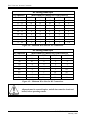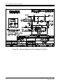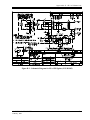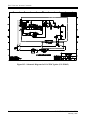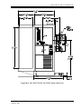
1
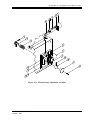
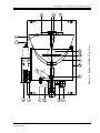
Film-Tech
The information contained in this Adobe Acrobat pdf
file is provided at your own risk and good judgment.
These manuals are designed to facilitate the
exchange of information related to cinema
projection and film handling, with no warranties nor
obligations from the authors, for qualified field
service engineers.
If you are not a qualified technician, please make no
adjustments to anything you may read about in these
Adobe manual downloads.
www.film-tech.com
CHRISTIE
INCORPORATED
INSTRUCTIONS
FOR
INSTALLATION AND OPERATION
OF
SLC SERIES
XENON CONSOLE
SLC 20/30/40/45/45R/70
TD-641 REV. D
CHRISTIE INCORPORATED
10550 Camden Drive
Cypress, CA 90630
714-236-8610 Fax: 714-229-3185
Operator’s Manual
Xenon Console, Model SLC 20/30/40/45/45R/70
TD641, Rev. D
Manufactured Under U.S. Patents 3,843,879 and 5,054,909
Other Patents Pending
The information in this document is subject to change without notice and does not represent a
commitment on the part of CHRISTIE INCORPORATED (hereinafter referred to as CHRISTIE).
CHRISTIE does not assume responsibility for errors that may appear in this document.
CHRISTIE or its subsidiaries, designated representatives, and any other vendor of the SLC
Xenon Console are not responsible in any way for any liabilities or loss resulting from the use
or misuse of this document.
Copyright © 1999 by CHRISTIE INCORPORATED
All Rights Reserved
All copyrights and trademarks are the property of their respective owners.
CHRISTIE
INCORPORATED
10550 Camden Drive
Cypress, CA 90630
Telephone 714-236-8610
FAX 714-229-3185
TABLE OF CONTENTS
TABLE OF CONTENTS ............................................................................ i
LIST OF FIGURES AND TABLES ............................................................ iii
1. Introduction ........................................................................................1-1
1.1. Contents of the Manual.................................................................................................. 1-1
1.2. Who Should Use This Manual?..................................................................................... 1-1
1.3. Special Notices .............................................................................................................. 1-2
1.3.1. Warning .................................................................................................................. 1-2
1.3.2. Caution ................................................................................................................... 1-2
1.3.3. Note ........................................................................................................................ 1-2
2. Safety Precautions.............................................................................2-1
2.1.
2.2.
2.3.
2.4.
2.5.
Wear Protective Clothing .............................................................................................. 2-1
Allow Lamp to Cool ...................................................................................................... 2-2
Disconnect AC Lines Before Entering Console ............................................................ 2-2
Do Not Look Directly at Lamp...................................................................................... 2-2
Avoid Fire Hazards........................................................................................................ 2-3
3. General Description ...........................................................................3-1
3.1. The Xenon Lamp ........................................................................................................... 3-1
4. Installation Procedures .....................................................................4-1
4.1. Unpacking...................................................................................................................... 4-1
4.2. Installation ..................................................................................................................... 4-1
4.2.1. Leveling Feet .......................................................................................................... 4-1
4.2.2. Door Panels ............................................................................................................ 4-4
4.2.3. Venting ................................................................................................................... 4-4
4.2.4. Mounting the Projector........................................................................................... 4-5
4.3. Electrical Connections ................................................................................................... 4-5
4.3.1. Verify Voltage ........................................................................................................ 4-5
4.3.2. Wiring Hook-Up..................................................................................................... 4-5
5. Alignment and Checkout Procedures ..............................................5-1
5.1. Mechanical Alignment................................................................................................... 5-1
5.2. Installation of Xenon Lamp ........................................................................................... 5-1
6. Operating the SLC..............................................................................6-1
6.1.
6.2.
6.3.
6.4.
6.5.
Safety Review................................................................................................................ 6-1
Starting and Operating the SLC..................................................................................... 6-1
Optical Alignment and Adjustment ............................................................................... 6-4
Tilt Adjustment.............................................................................................................. 6-5
Replacing the Lamp....................................................................................................... 6-5
CHRISTIE INCORPORATED
February, 1999
i
SLC Series Xenon Console
6.5.1. Removing the Lamp............................................................................................... 6-5
6.5.2. Installing a New Lamp ........................................................................................... 6-5
6.5.3. Defective Lamps .................................................................................................... 6-5
7. Maintenance and Adjustments..........................................................7-1
7.1. Before Opening the Console ......................................................................................... 7-1
7.2. Cleaning Optical Surfaces ............................................................................................. 7-1
7.2.1. Cleaning Dust......................................................................................................... 7-2
7.2.2. Cleaning Grease ..................................................................................................... 7-2
7.3. Maintaining Other Surfaces........................................................................................... 7-2
7.3.1. Blower .................................................................................................................... 7-3
7.3.2. Igniter ..................................................................................................................... 7-3
7.3.3. Air Flow Interlocks ................................................................................................ 7-3
7.4. Aligning Lamphouse Without Alignment Tools........................................................... 7-3
7.5. Xenon Lamp Autofocus Adjustments (Option ABF).................................................... 7-4
7.5.1. Autofocus Adjustment Procedures......................................................................... 7-4
7.6. Optimizer Reflector....................................................................................................... 7-6
7.7. Electrical Connections................................................................................................... 7-6
7.8. Airflow .......................................................................................................................... 7-6
7.9. Remote Lamp Adjustment Control (Option RBA) ....................................................... 7-6
8. Troubleshooting .................................................................................8-1
8.1. Malfunction: Power Supply Does Not Start.................................................................. 8-1
8.2. Malfunction: Lamp Does Not Ignite ............................................................................. 8-2
8.3. Power Supply Output Is Low Or Not Steady ................................................................ 8-2
WARRANTY .......................................................................................... W-1
Appendix A: Assembly Diagrams and Parts Lists.............................. A-1
ii
CHRISTIE INCORPORATED
February, 1999
Table of Contents
LIST OF FIGURES AND TABLES
Figure 2-1:
Figure 4-1:
Figure 4-2:
Figure 4-3:
Figure 4-4:
Figure 4-5:
Figure 5-1:
Figure 6-1:
Figure 6-2:
Table 8-1:
Table 8-2:
Table 8-3:
Figure A-1:
Table A-1:
Figure A-2:
Table A-2:
Figure A-3:
Table A-3:
Figure A-4:
Table A-4:
Figure A-5:
Table A-5:
Table A- 6:
Figure A-7:
Table A-7:
Protective Clothing Safety Kit Contents .............................................................. 2-1
SLC Xenon Lamp Console (Front View) ............................................................ 4-2
SLC Xenon Lamp Console (Rear View) ............................................................. 4-3
Minimum and Maximum Exhaust Airflow Requirements for SLC Consoles..... 4-4
Minimum Wire Sizes for AC Connections .......................................................... 4-6
Minimum Wire Sizes for DC Connections .......................................................... 4-6
Plenum, Top View ............................................................................................... 5-2
Control Panel........................................................................................................ 6-2
Optical Alignment of Xenon Lamp...................................................................... 6-4
Troubleshooting for Power Supply Does Not Start ............................................. 8-1
Troubleshooting for Lamp Does Not Ignite......................................................... 8-2
Troubleshooting for Power Supply Output Low or Not Steady .......................... 8-2
Autofocus Assembly ........................................................................................... A-2
Parts List for Autofocus Assembly ..................................................................... A-3
SLC Xenon Lamp Console (Front View) ........................................................... A-4
Parts List for SLC Xenon Lamp Console (Front View) ..................................... A-5
SLC Xenon Lamp Console (Rear View) ............................................................ A-6
Parts List for SLC Xenon Lamp Console (Rear View)....................................... A-7
Control Panel....................................................................................................... A-9
Parts List for Control Panel............................................................................... A-10
Manual Lamp Adjustment Assembly................................................................ A-11
Parts List for Manual Lamp Adjustment Assembly.......................................... A-12
Parts List for Plenum, All Models (Top View)................................................. A-14
Power Supply .................................................................................................... A-15
Power Supply .................................................................................................... A-16
CHRISTIE INCORPORATED
February, 1999
iii
1
1.
INTRODUCTION
1.1.
CONTENTS
OF THE
MANUAL
This manual contains installation, operation, and operator maintenance procedures for
CHRISTIE SLC Xenon Console. The material covered includes:
• General description
• Installation and assembly
• Alignment and checkout procedures
• Operating the SLC
• Troubleshooting.
1.2.
WHO SHOULD USE THIS MANUAL?
This manual provides information suitable for various purposes.
All users should read Section 2: Safety Precautions.
Do not install, operate, maintain, or repair the SLC Xenon Lamp
Console unless you have read Section 2, are familiar with the safety
precautions, and have followed all warnings and instructions.
WARNING
For details on operating the projector and for general information, see:
• Section 3: General Description
• Section 4: Installation Procedures
• Section 5: Alignment and Checkout Procedures
• Section 6: Operating the SLC.
Before performing adjustments and periodic maintenance during normal operation, see:
• Section 4: Installation Procedures
• Section 5: Alignment and Checkout Procedures
• Section 7: Maintenance and Adjustments
• Section 8: Troubleshooting.
If a problem occurs, see:
• Section 8: Troubleshooting.
Additional reference information is contained in the appendices.
CHRISTIE INCORPORATED
February, 1999
1-1
SLC Series Xenon Console
1.3.
SPECIAL NOTICES
Three kinds of specific notices are used within this manual to emphasize specific
information.
1.3.1.
WARNING
WARNING: Indicates the presence of a hazard that can cause personal
injury if the hazard is not avoided.
WARNING
1.3.2.
CAUTION
CAUTION: Indicates the presence of a hazard that could cause damage
to the system.
1.3.3.
NOTE
NOTE: Provides additional information.
1-2
CHRISTIE INCORPORATED
February, 1999
2
2.
SAFETY PRECAUTIONS
This section highlights the major dangers of working with the SLC Xenon Console.
Appropriate safety measures must be taken at all times.
2.1.
WEAR PROTECTIVE CLOTHING
POSSIBLE
EXPLOSION
HAZARD!
WARNING
Xenon compact arc lamps are under high pressure. The lamps must be handled with great
care. They may explode if dropped or mishandled. Whenever the protective cover is
removed from the lamp, authorized protective clothing must be worn!
Protective clothing includes, but may not be limited to, rubberized cotton gloves, doublelayer 0.040-inch acetate face shield, and quilted ballistic nylon jacket. A Protective Clothing
Safety Kit (Part Number 598900-095) is available from CHRISTIE. Figure 2-1 lists the
contents of the Safety Kit.
Wear protective clothing when protective cover is removed from lamp.
WARNING
Instructions from CHRISTIE regarding protective clothing are subject to change. Any local
or federal specifications take precedence.
Part Number
Item
598900-092
Safety Jacket
598900-093
Safety Mask
598900-094
Safety Gloves
Figure 2-1: Protective Clothing Safety Kit Contents
CHRISTIE INCORPORATED
February, 1999
2-1
SLC Series Xenon Console
2.2.
ALLOW L AMP
TO
COOL
If the lamp has been in use, wait at least ten minutes after shut-off
before opening the lamp housing.
WARNING
The ten-minute waiting period allows the internal lamp pressure to drop to a level at which it
is safe to work while wearing the authorized protective clothing. Again, always wear
protective clothing when the protective cover is removed from the lamp.
2.3.
D I S C O N N E C T AC L I N E S B E F O R E E N T E R I N G C O N S O L E
Pull the AC disconnects in the AC lines before entering the console.
WARNING
Always turn off and disconnect power lines before entering the console. This protects
against accidental electrical shock.
2.4.
DO NOT LOOK DIRECTLY
NEVER
LOOK
AT
LAMP
DIRECTLY
AT
THE
LAMP!
WARNING
Serious and permanent eye damage can be caused by the ultraviolet radiation of the lamp.
Never attempt to open the console while the lamp is on. Always follow directions for
opening console and exposing the Xenon lamp. (See Section 5.2.)
2-2
CHRISTIE INCORPORATED
February, 1999
CHAPTER NUMBER: TITLE
2.5.
AVOID FIRE H AZARDS
FIRE HAZARD: Keep hands, clothes, and combustible material away
from the concentrated light beam in front of the snood.
WARNING
Use extreme caution when working around the SLC Xenon Console. Fire danger may arise
from heat, electrical current, or the concentrated light beam emitted by the Xenon lamp.
CHRISTIE INCORPORATED
February, 1999
2-3
3
3.
GENERAL DESCRIPTION
This SLC Xenon Console is a series of projection illuminator systems that combine the
rectifier DC power supply and projector base with a Xenon lamphousing into a single,
integrated unit with a minimum of installation and wiring expense. These consoles are
designed for use with any standard 35-mm or 35/70-mm motion picture projector head.
3.1.
THE XENON LAMP
The SLC Xenon Console utilizes a highly efficient optical system to obtain maximum light
output with extreme ease of operation and high reliability. This is accomplished by using a
horizontally operated Xenon lamp within a deep, explosion-proof reflector. For maximum
efficiency, the reflector has a computer-generated, aspheric shape. The high-voltage igniter
(Item 2 in Figure A-3), required for starting the Xenon lamps, is included within the
enclosure.
Authorized protective clothing must be worn when protective cover is
removed from lamp.
WARNING
For lamp description, recommendations, and warranty information, see the CHRISTIE (or
equivalent) lamp instructions.
SLC Consoles are equipped with a double interlock system on the lamp
access doors to extinguish the lamp if the enclosure is accidentally
opened. Keyed locks are provided on all access doors.
CHRISTIE INCORPORATED
February, 1999
3-1
4
4.
INSTALLATION PROCEDURES
4.1.
UNPACKING
Follow these instructions if the unit is crated.
CHRISTIE recommends that the unit be moved to the installation site before
uncrating.
1. Be sure container is upright.
2. Open crate and remove packing.
3. Carefully remove unit from crate.
4. Thoroughly inspect unpacked unit for damage that may have occurred during shipping.
Any damage discovered should be reported to the transportation company at
once for inspection and filing of claim.
4.2.
INSTALLATION
Place console in intended operating location in projection booth.
4.2.1.
LEVELING FEET
Install four (4) leveling feet by screwing one into each of the four corners underneath base
until about 1 inch of thread remains exposed. (See Item 8 in Figure 4-1.)
CHRISTIE recommends carefully tilting the console to one side to install
the first two feet, then tilting it to the other side to install the other two
feet.
CHRISTIE INCORPORATED
February, 1999
4-1
SLC Series Xenon Console
1: Exhaust Duct Connector (195713-001)
2: Air Switch Assembly (195557-002)
3: Lamp Support, Positive (193959-001)
4: Circuit Breaker, 30 A (573303-005)
Circuit Breaker ,20 A (573102-009)
Circuit Breaker, 15 A (573101-020)
5: Circuit Breaker, 40 A (573304-001)
Circuit Breaker, 30 A (573022-022)
Circuit Breaker, 20 A (573302-003)
6: Tap Switch (111972-002)
7: Tilt Adjust Bolt (515500-177)
8: Leveling Foot (520650-003)
9: Blower (SLC 20/30) (528040-005)
Blower (SLC 40,45,70) (598931-645)
10: Reflector (SLC 20/30) (195206-003)
Reflector (SLC 40/45) (195891-001)
Reflector (SLC 45R) (195710-001)
Reflector (SLC 70) (195572-002)
11: Snood (SLC 20, 30) (195741-001)
Snood (SLC 40/45/70) (195415-001)
12: Lamp Connector (+) (193718-001)
13: Projector Mnt. (20/30) (195303-001)
Projector Mnt. (40/45/70) (195738-001)
14: Alignment Adjust (515500-141)
15: Douser Handle (192121-001)
16: Guard Air Intake (195684-001)
17: Power Supply 2kW 208/230v (195462-001)
Power Supply 2kW 380/415v (195462-004)
Power Supply 3kW 208/230v (195463-001)
Power Supply 3kW 380/415v (195463-004)
Power Supply 4kW 208/230v (195464-001)
Power Supply 4kW 380/415v (195464-004)
Power Supply 7kW 208/230v (195556-001)
Power Supply 7kW 380/415v (195556-004)
Figure 4-1: SLC Xenon Lamp Console (Front View)
4-2
CHRISTIE INCORPORATED
February, 1999
4: Installation Procedures
1: Air Switch Assy. (195557-001)
Air Switch, 2nd Blower (195557-003)
2: Igniter, IGA-10 (116715-001)
IGA-15M (117124-001)
IGA-25DC (196370-001)
3: Door Interlock (578000-034)
4: Capacitor (SLC 20, 30) (530106-302)
(SLC 40, 45, 70) (530122-009)
5: Terminal Strip (586211-001)
6: Control Assy, 60 Hz (20, 30) (114173-002)
50 Hz (SLC 20) (114173-011)
50 Hz (30, 40, 45, 70) (114173-010)
60 Hz (40, 45, 70) (114173-001)
7: Power Input Terminal (586210-601)
8: Heat Sink Assembly (20) (114109-001)
(SLC 30) (114109-002)
(SLC 40) (114099-001)
(SLC 45, 45R, 70) (195569-001)
9: Leveling Foot (520650-003)
10: Fan Guard (598931-496)
11: Transformer, 60 Hz (20) (116845P001)
50 Hz (SLC 20) (194701P001)
60 Hz (SLC 30) (115948P001)
50 Hz (SLC 30) (194702P001)
60 Hz (SLC 40) (116994P001)
50 Hz (SLC 40) (119384P001)
60 Hz (45, 45R, 70) (195775P001)
50 Hz (45, 45R, 70) (196186-001)
12: Lamp Adjustment PCB
Automotorized (195315-001)
Motorized(195315-002)
13: Lamp Adj., Manual (195800-001)
Motorized (195800-002)
Autofocus Mot. (195800-003)
Autofocus Man. (195800-004)
Motorized Man. (195800-005)
14: Lamp Current Adj. (111972-002)
15: Contactor
120v(SLC 20, 30) (571320-001)
120v,(SLC 40, 45, 70) (571340-001)
230v, (SLC 20, 30) (571320-002)
230v, (SLC 40, 45, 70) (571340-001)
16: Console Tilt Option (195535-001)
Figure 4-2: SLC Xenon Lamp Console (Rear View)
CHRISTIE INCORPORATED
February, 1999
4-3
SLC Series Xenon Console
4.2.2.
DOOR PANELS
All three door panels are removable for easier access to the interior of the console during
installation and maintenance.
To remove door panel:
1. Unlock key-lock.
2. Open door.
3. Push down on spring-loaded pin hinge.
4. Remove panel.
To install door panel, reverse the above procedure.
4.2.3.
VENTING
It is necessary to vent hot exhaust air from console to the outside of the building.
1. Connect a eight-inch inner-diameter, flexible, fireproof ducting material to exhaust duct
(Item 1 in Figure A-2) on top of lamphouse.
2. Ensure that there are no obstructions in ducting, and that air intake openings of console
are unobstructed.
If ozone-free lamps are used, a short, vertical exhaust stack may be used, provided local
codes do not require the exhaust to be vented directly outside.
Minimum and maximum exhaust airflow requirements for all SLC series models are shown
in Figure 4-3.
Model
Minimum Exhaust (ft3/min)
Maximum Exhaust (ft3/min)
SLC 20
300
400
SLC 30
350
450
SLC 40
450
550
SLC 45, SLC 45R
550
750
SLC 70
750
900
Figure 4-3: Minimum and Maximum Exhaust Airflow Requirements for SLC Consoles
4-4
CHRISTIE INCORPORATED
February, 1999
4: Installation Procedures
4.2.4.
MOUNTING
THE
PROJECTOR
The SLC Console includes a standard projector mounting bracket for CHRISTIE P35
projectors. If any other model projector is to be mounted, contact the CHRISTIE factory.
1. Mount projector on projector mounting bracket (Item 13 in Figure A-2).
2. Ensure that projector is level and in line with console before tightening mounting bolts.
3. Verify that all four (4) bolts are installed and securely tightened.
4.3.
ELECTRICAL CONNECTIONS
SLC Consoles are factory wired and tested. All functions have been carefully tested and
calibrated to prevent problems during installation and operation.
Before connecting, pull AC disconnect switch in all AC supply lines.
WARNING
4.3.1.
VERIFY VOLTAGE
Check the AC voltage shown on the console nameplates. Then measure the AC supply
voltages with a voltmeter. Verify that the measured voltages do not differ by more than 10%
from the rated nominal values of the unit.
4.3.2.
WIRING HOOK-UP
1. Pull 3-phase wires and single-phase and ground wires through one of knock-out holes
located on front of non-operating side on foot of console. Check charts in Figure 4-4 and
Figure 4-5 for correct wire size.
Grounding wire (green) must be at least as large in diameter as largest
wire used for AC power connections.
WARNING
2. Connect 3-phase wires to Terminal Board TB2–L1, TB2–L2, and TB2–L3.
3. Connect single-phase wires to TB2–L1, Neutral, marked 115V single-phase. Connect
ground wire to TB2–ground.
4. Check Schematic and/or Automation Manual for wiring hook-up to TB5. These
connections are for projector, sound, changeover douser, and auditorium functions.
5. Hook up all wires as required in above instructions.
CHRISTIE INCORPORATED
February, 1999
4-5
SLC Series Xenon Console
AC Wiring Hook-Ups
AC AMPERES
WIRE DIAMETER (AWG) PER CABLE LENGTH
PER PHASE
50 FT
100 FT
150 FT
200 FT
250 FT
0 - 10
11 - 15
16 - 20
14
14
12
14
12
10
12
10
8
10
8
8
10
6
6
21 - 25
26 - 35
36 - 45
10
8
6
10
8
6
8
6
4
6
4
4
4
4
3
46 - 60
61 - 70
71 - 80
4
3
2
4
3
2
4
3
2
3
2
1
1
1
1/0
Figure 4-4: Minimum Wire Sizes for AC Connections
DC Wiring Hook-Ups
DC AMPERES
WIRE DIAMETER (AWG) PER CABLE LENGTH
PER PHASE
25 FT
50 FT
75 FT
100 FT
20
40
10
10
10
8
8
6
6
4
60
80
100
8
4
4
6
4
3
4
2
1
2
1
1/0
125
150
200
3
3
2
1
1
1/0
1/0
2/0
3/0
2/0
3/0
4/0
Figure 4-5: Minimum Wire Sizes for DC Connections
All panels must be secured in place, and all doors must be closed and
locked, before operating console.
WARNING
4-6
CHRISTIE INCORPORATED
February, 1999
5
5.
ALIGNMENT AND CHECKOUT PROCEDURES
5.1.
M E C H A N I C A L AL I G N M E N T
When installing an SLC console equipped for 35/70 mm operation, be certain
that the optical bench assembly is in the correct sliding position: FORWARD
for 70 mm, to the REAR for 35 mm. Contact CHRISTIE for more information
or for assistance.
All SLC Consoles are optically aligned at the factory. The optical bench or plenum assembly
is aligned with an optical laser alignment tool. At installation, if not already mounted, the
projector must subsequently be mechanically aligned to the console snood. This is done by
adjusting the jackscrews on the projector mounting bracket (Up/Down, Left/Right). (See
Item 14 in Figure A-2.)
A satisfactory mechanical alignment can readily be obtained without the use of any special
tools.
5.2.
INSTALLATION
OF
XENON LAMP
Authorized protective clothing must be worn when protective cover is
removed from lamp.
WARNING
1. Turn off all AC power.
2. Open top door on the operating (right) side of console.
3. Remove plenum access cover.
4. Verify that lamp model number and rating correspond to the rating on the console
nameplate or lamp rating sticker.
5. Remove lamp from package.
Do not touch the quartz body of the lamp with bare hands at any time.
Do not apply any bending or twisting force to the quartz body of the
lamp.
WARNING
CHRISTIE INCORPORATED
February, 1999
5-1
SLC Series Xenon Console
1: Igniter, IGA-10 (116715-001)
Igniter, IGA-15M (117124-001)
Igniter, IGA-25DC (196370-001)
2: Terminal Board, TB4 (586210-602)
3: Focus Screw (195182-001)
4: Wheel, Manual Lamp Adjustment (195190-001)
5: Motor, Synchronous, Lamp Adjustment, 50 RPM (582000-002)
6: Flex Braid Negative Lamp Lead (SLC) (195224-002)
7: Negative Lamp Connector (194513-003)
8: Allen Screw, #8-32 x 0.75 in L (598931-046)
9: Reflector, 2000-3000 W Lamp (SLC 20, 30) (195206-003)
Reflector, 4500 W (SLC 45R) (195710-001)
Reflector, 4000 W (SLC 40, 45) (195891-001)
Reflector, 7000 W (SLC 70) (195572-001)
10: Cover Support, Plenum (195171P001)
Cover Front Support, Plenum (195172P001)
11: Magnet, Arc Stabilizer (515000-092)
12: Xenon Lamp, 1600 W Adapter (CXL-16S) *
Xenon Lamp, 2000 W (CXL-20) *
Xenon Lamp, 3000 W (CXL-30) *
Xenon Lamp, 4000 W (CXL-40) *
Xenon Lamp, 4500 W (CXL-45) *
Xenon Lamp, 6000 W (CXL-60) *
Xenon Lamp, 7000 W (CXL-70) *
13: Shaft Coupling (195532-001)
14: Lamp Support Arm (193959-001)
15: Insulator, Forward Lamp Support (193958-002)
16: Forward Adapter, Positive Connector (191925-002)
17: Lamp Lead, Positive Connector (SLC 20, 30) (193718-001)
Lamp Lead, Positive Connector (SLC 40) (195446-001)
Lamp Lead, Positive Connector, (SLC 45, 70) (195446-002)
* Specify SLC model when ordering.
Figure 5-1: Plenum, Top View
5-2
CHRISTIE INCORPORATED
February, 1999
4: Alignment and Checkout Procedures
6. Remove knurled nut and locking star washer (if present) from negative (cathode) base pin
of lamp.
7. Remove protective cover from lamp.
8. Insert threaded cathode end of lamp into negative lamp connector located in rear of
plenum. (See Item 7 in Figure A-6.)
9. Screw lamp in place until it bottoms out in lamp connector.
10. Rest positive (anode) end on forward wire cradle.
11. Install positive lamp connector. (See Figure 5-1.)
12. Tighten clamping screws in positive and negative lamp connectors. (See Items 7 and 17,
Figure 5-1).
Proper electrical contact is essential in order to prevent resistance in the
positive and negative lamp connectors.
13. Verify that positive lead from lamp to igniter does not touch or run close to any metal
parts of lamphouse or mirror.
Leads that are too close to any metal parts will cause arcing during starting
pulse, and lamp may not ignite.
14. If quartz body of lamp is accidentally touched with bare hands or becomes dirty, clean
quartz body of lamp with alcohol and carefully wipe with soft cloth and distilled water.
Authorized protective clothing must be worn when cleaning lamp.
WARNING
15. Replace plenum cover plate and close operating door.
Interlock switches prevent the system from operating if the top door on the
operator side and the door on the non-operating side are not closed and
locked.
CHRISTIE INCORPORATED
February, 1999
5-3
6
6. OPERATING THE SLC
6.1.
SAFETY REVIEW
Do not install, operate, maintain, or repair the SLC Xenon Lamp
Console unless you have read Section 2, are familiar with the safety
precautions, and have followed all warnings and instructions.
WARNING
•
Never look directly at the Xenon lamp.
Serious and permanent eye damage can be caused by the ultraviolet radiation of the lamp.
Under no condition should the console be opened except as described in Section 7,
below.
•
Do not open the lamp compartment for at least ten minutes after switching the lamp
off.
•
Always wear authorized protective clothing when opening the lamp compartment or
handling an unprotected lamp.
•
Pull the AC disconnects in the AC lines before entering the console.
6.2.
STARTING
AND
OPERATING
THE
SLC
Before starting the lamp, check the rated lamp operating current. The rated lamp operating
current is found on the lamp data sheet in the box in which the lamp is shipped.
1. Verify that DC Power ON/OFF Switch (Item 7 in Figure 6-1) is in OFF position.
2. Energize all AC power to console. Pilot lamp (Item 6 in Figure 6-1) will light.
The power supply should not energize until the DC Power ON/OFF Switch is
switched ON.
3. Set current adjust on power supply (Item 6 in Figure 4-1) to medium position.
4. Verify that lamphouse cooling is operating. Interlock ready light (Item 5 in Figure 6-1)
should be ON, indicating that interlock circuit is closed.
CHRISTIE INCORPORATED
February, 1999
6-1
SLC Series Xenon Console
SLC 20, 30
1: Meter, 150 Amp (535112-321)
2: Volt/Ampere PCB (195643-0010
3: Timer, 120 VAC, 60 Hz (581399-008)
Timer, ET, 120 VAC, 60 Hz (581399-015)
Timer, ET, 120 VAC, 50 Hz (581399-016)
Timer, ET, 240 VAC, 60 Hz (581399-017)
4: Rocker Switch, SPDT (578712-002)
5: Indicator, Green, 120 VAC (195138-001)
Indicator, Green, 250 VAC (546700-054)
6: Indicator, Amber, 380 VAC (195139-001)
Indicator, Amber, 440 VAC (195139-002)
Indicator, Amber, White Base (546700-038)
SLC 40, 45, 70
7:
8:
9:
10:
11:
12:
Rocker Switch, DPST, ON/OFF (578900-026)
Rocker Switch, DPST; MOM ON (578900-027)
Rocker Switch, SPDT; MOM (578900-040)
Terminal Receptacle (524310-006)
Rocker Switch, SPDT; ON/ON (578900-042)
Control Panel, Manual (195756-001)
Control Panel, Motorized, Auto-Focus (195756-002)
Control Panel, Motorizedl Manual and
Auto-Focus Manual (195756-003)
13: Meter, 200 Amp (535112-317)
Figure 6-1: Control Panel
6-2
CHRISTIE INCORPORATED
February, 1999
7: Operating the SLC Xenon Console
If the light is not on when the pilot lamp (Item 5 in Figure 6-1) is on,
check for an open switch (door switch, blower switch, or exhaust stack
switch) in the interlock circuit.
5. If Automation Control is not used, set DC Power ON/OFF switch to ON position.
If Automation Control (automatic remote control) is used, leave AC ON/OFF switch in
OFF position. Lamp operation is controlled by automation relay. If this relay
malfunctions, lamp can be ignited by setting DC Power ON/OFF Switch to ON.
6. Verify that douser handle (Item 15 in Figure 4-1) is closed (in UP position).
7. Turn DC Power ON/OFF Switch to ON position. Lamp will ignite automatically. If
lamp does not ignite, momentarily press the Manual Start Button (Item 8 in Figure A-1)
to strike lamp.
8. Check ammeter reading and verify that rated lamp current is not exceeded.
Do not allow the current to exceed the rated maximum lamp current or
drop below 10% of that value.
WARNING
9. If current is too high or too low, use tap switch to adjust power supply to proper current.
If, after ten-minute warm-up period, correct current cannot be obtained with tap switch:
a) Turn unit off.
b) Pull AC disconnect switch.
c) Open left side door of console.
d) Change Hi-Lo links (see Item 6 in Figure 2-1) as necessary.
Turn the DC Power ON/OFF Switch to OFF before rotating the tap
switch.
WARNING
10. Extinguish lamp by turning DC Power ON/OFF switch to OFF position.
Do not service the power supply until it has been turned off for at least
two (2) minutes. This allows the capacitors to discharge.
WARNING
CHRISTIE INCORPORATED
February, 1999
6-3
SLC Series Xenon Console
6.3.
O P T I C A L AL I G N M E N T
AND
AD J U S T M E N T
Repeat this procedure every time a lamp is changed. (See illustrations in Figure 6-2.)
1. After lamp has been started and operated as described in Section 6.2, open douser.
Observe dark spot projected on screen.
2. Using control panel (Figure 6-1), adjust lamp focus until dark spot is clearly defined.
3. Center dark spot using vertical and lateral adjustments (Item 9 in Figure 6-1).
4. Move lamp forward. Light intensity should be equal on both sides of dark spot. If light
intensity is not equal on both sides of dark spot, use vertical and/or lateral adjustments to
balance light intensity.
5. When light intensity is balanced, move lamp back through FOCUS. Light intensity
should again be equal on both sides of dark spot.
If light intensity is not equal on both sides of dark spot, recheck Section 5.1 (Mechanical
Alignment) and repeat Steps 1 – 5.
6. Close the douser and replace the projector lens in the projector.
7. Again open the douser and make final lamp adjustments, if necessary, to obtain
maximum and uniform light on the screen.
Correct picture
without projector lens
installed.
Lamp centering too
far to left; correct
with Left/Right lamp
adjustment.
Correctly centered
bright spot with scope
lens and aperture
plate.
Figure 6-2: Optical Alignment of Xenon Lamp
6-4
CHRISTIE INCORPORATED
February, 1999
7: Operating the SLC Xenon Console
6.4.
TILT ADJUSTMENT
The SLC Console is optionally equipped with a jackscrew for easy tilt adjustment. It is
located in the bottom rear of the console, and is accessible from either side. (See Item 16 in
Figure 4-2.)
1. Loosen all four (4) hold-down bolts. (See Item 7 in Figure 4-1.)
2. Turn jackscrew using 3/4-inch wrench or ratchet. Turn jackscrew clockwise to tilt
console downward. Turn jackscrew counterclockwise to tilt console upward.
3. After reaching correct tilt angle, securely tighten all four hold-down bolts.
6.5.
REPLACING
THE
LAMP
In accordance with safety precautions, always be certain that the lamp has cooled for at least
10 minutes before replacing it.
Authorized protective clothing must be worn when replacing lamp.
WARNING
6.5.1.
REMOVING
THE
LAMP
CHRISTIE recommends that lamps be replaced before running time exceeds 120% of
warranted lifetime. Check running time using elapsed time indicator on control panel (Item 3
in Figure 6-1).
1. Loosen set screws on positive and negative lamp connectors.
2. Unscrew lamp and remove from reflector. Immediately put protective cover on lamp.
3. Record hours that lamp has been used.
Record the elapsed time reading for the old lamp when installing a new lamp.
6.5.2.
INSTALLING
A
NEW LAMP
Install the new Xenon lamp according to the directions in Section 5.2.
6.5.3.
DEFECTIVE LAMPS
Defective lamps under warranty are to be returned to the dealer who provided the lamp in
their protective cover and proper packing. They must be returned to CHRISTIE
INCORPORATED. The Warranty Claim Forms supplied with the lamp must be filled out
CHRISTIE INCORPORATED
February, 1999
6-5
SLC Series Xenon Console
completely. All portions of the failed lamp including electrodes must accompany the lamp to
aid CHRISTIE in evaluating the defect.
6-6
CHRISTIE INCORPORATED
February, 1999
7
7.
MAINTENANCE AND ADJUSTMENTS
Wear protective clothing when protective cover is removed from lamp.
WARNING
7.1.
BEFORE OPENING
THE
CONSOLE
Perform these checks at least every 60 days or 500 hours.
Pull the AC disconnects in the AC lines before entering the console.
WARNING
1. Check contact surfaces of positive (anode) and negative (cathode) connections for
cleanliness at regular intervals. Clean electrical contact surfaces as necessary to prevent
contact resistance from scorching connectors.
2. Clean air intake openings.
3. Verify that all electrical and lamp connections are tight.
7.2.
CLEANING OPTICAL SURFACES
Repeated cleaning of optical surfaces can be more harmful than helpful.
Clean only when surfaces are excessively dirty.
The exposed optical surfaces of the lamphouse occasionally require cleaning. For
optimum system performance, inspect mirror surface for cleanliness every two weeks.
CHRISTIE INCORPORATED
February, 1999
7-1
SLC Series Xenon Console
Always remove the lamp before cleaning the reflector.
WARNING
7.2.1.
CLEANING DUST
For surfaces that are dusty but do not have smudges, fingerprints, or grease marks:
1. Brush dust from surface with camel-hair brush.
2. Blow remaining dust away with compressed air.
7.2.2.
CLEANING GREASE
For surfaces that are smudged or have oil or grease smears:
1. Moisten cotton pad with light detergent solution. Pad should be well moistened but not
dripping wet.
2. Gently swab exposed lens or mirror surface, using spiral motion and working from center
outward toward edge of surface.
3. Sponge up moisture with cheesecloth or lens tissue.
Always sponge with fresh cheesecloth or lens tissue. Do not wipe with
material that has been used before. Throw cheesecloth or lens tissue away
after one use.
4. Dampen cotton pad with methyl alcohol. Wipe surface, using spiral motion from center
to edge, in one continuous motion.
5. Dry exposed surface with dry cotton pad or with lens tissue.
6. Repeat procedure above as required.
7. When exposed lens or mirror surface is dry and clean, loosen any remaining lint with
brush and blow clean with compressed air.
7.3.
MAINTAINING OTHER SURFACES
Surfaces other than the optical surfaces require periodic maintenance to keep the lamphouse
in good operating condition. These items are:
7-2
•
Blower
•
Igniter
•
Air flow interlocks.
CHRISTIE INCORPORATED
February, 1999
7: Operating the SLC Xenon Console
These items should be cleaned approximately every six months under normal environmental
conditions. Equipment in very dusty or otherwise contaminated areas may require more
frequent maintenance.
7.3.1.
BLOWER
The blower impeller and motor should be cleaned to prevent build-up of contaminant on both
the blower impeller surfaces and on the blower motor. Proper operation of the lamp is
dependent on providing adequate cooling air flow. A dirty blower may not provide proper
air flow, causing the lamp and lamphouse to operate at temperatures that are higher than
desirable.
1. Clean loose dirt from blower impeller with vacuum cleaner.
2. Use brush with hot water and suitable detergent to remove dirt that cannot be vacuumed
off.
When cleaning the impeller, be careful not to bend the blades or to loosen the
balancing weights.
3. Every six months, lubricate blower motor by applying three to four drops of light
machine oil to oil holes in motor housing.
7.3.2.
IGNITER
Periodically clean the high voltage terminal and insulator to prevent accumulation of dust or
dirt.
7.3.3.
AIR FLOW INTERLOCKS
Periodically check and, if necessary, clean the air flow interlock vanes to remove
accumulated dirt.
7.4.
A L I G N I N G L A M P H O U S E W I T H O U T AL I G N M E N T T O O L S
1. Inspect reflector and lens and clean if necessary.
2. Inspect lamp for dirt or fingerprints. Clean if required.
3. Center lamp adjustments in rear of lamphouse to midpoint of their range.
4. Install lamp in lamphouse.
5. Use ruler to verify that positive end of lamp is centered in reflector from top to bottom
and side to side. If not centered, adjust to center position by adjusting the front lamp
support.
6. For best results: With ruler, verify that positive end of lamp is centered left to right in
reflector within 1/16 in. If not centered, adjust front lamp support to center lamp.
CHRISTIE INCORPORATED
February, 1999
7-3
SLC Series Xenon Console
The following adjustments must be made with the rear lamp adjustments
centered.
7. When all preliminary adjustments are satisfactory, connect positive connector to anode
ferrule. To prevent arcing, keep anode lead clear of any metal parts.
8. With anode centered, firmly tighten anode and cathode clamping screws.
9. Replace plenum cover and doors of lamphouse.
10. Set current control to lowest tap and start lamphouse.
11. Install scope lens and aperture.
12. Put light on screen and adjust lamp focus for maximum light.
13. Move console base sideways and adjust tilt until aperture is centered on screen.
14. Remove projector lens and adjust lamp "left and right." If bright dot does not pass
through center of dark shadow, adjust lamp "up and down" until it does. (See Figure
6-2.)
15. Adjust bright dot until it is centered behind dark shadow. (See Figure 6-2.)
16. Replace scope lens.
17. Adjust lamp focus until large bright spot with dark corners appears on screen. (See
Figure 6-2: Optical Alignment of Xenon Lamp). Spot must be centered and four corners
must be equal size. If spot is not centered, move projector left or right and up or down,
with respect to console, until spot is centered. Do not reposition lamp.
18. Repeat steps 14 through 17 until bright spot fills all four corners at same time lamp focus
control is adjusted. Barely fill corners with light and then stop. This is point of
maximum light.
19. Adjust current tap switch on rectifier for desired amount of light within current rating of
lamp.
7.5.
X E N O N L A M P A U T O F O C U S A D J U S T M E N T S (O P T I O N ABF)
The lamp autofocus is designed to give optimum light output in both scope and flat formats.
After proper settings have been established, the motorized lamp adjustment automatically
readjusts the lamp to its designated position. These adjustments are obtained by setting the
two limit switches (Items 15 and 16 in Figure A-1) to their proper positions.
7.5.1.
AU T O F O C U S AD J U S T M E N T P ROCEDURES
1. Connect signal wires.
24 VDC
Connect two signal wires (Scope/Flat) from automation programmer to TB6-1 and
TB6-2. (See Item 25 in Figure A-1.) Set switch S13 to DC mode. Provide 24 VDC
pulse (+/-) to activate latching relay for scope/flat format.
7-4
CHRISTIE INCORPORATED
February, 1999
7: Operating the SLC Xenon Console
115 VAC
Connect three signal wires (Scope/Flat) from automation programmer to TB6-1, TB6-2,
and TB6-3. (See Item 25 in Figure A-1.) Set switch S13 to AC mode. Provide 115 VAC
to TB6-1 or TB6-4 to activate latching relay for scope/flat format.
2. Turn autofocus switch (Item 11 in Figure 6-1) to ON (1).
3. Activate automation programmer for flat position. Observe that lamp focus adjustment
moves lamp forward. If the lamp adjustment moves in reverse:
24 VDC
Exchange the position of the two wires.
115 VAC
Exchange the position of the two wires of TB6-1 and TB6-3.
After correct travel has been obtained, proceed to next step.
4. Turn Autofocus switch to OFF (0).
5. Obtain desired light level on screen for flat format by adjusting up/down, left/right, and
forward/aft switches (Items 9 in Figure 6-1).
6. Adjust flat adjustment thumbscrew (Item 18A in Figure A-1): If green light (Item 26 in
Figure A-1) is ON, turn thumbscrew counterclockwise until light goes out. If green light
is not ON, turn thumbscrew clockwise until green light comes ON. Turn thumbscrew
back and forth several times to determine exact position where green light turns ON.
This position is correct setting for flat format.
7. Activate automation for scope format. Set desired light level on screen for scope format
by adjusting up/down, left/right, and forward/aft switches (Items 9 in Figure 6-1).
8. Adjust scope adjustment thumbscrew (Item 18B in Figure A-1): If red light (Item 27 in
Figure A-1) is ON, turn thumbscrew clockwise until light goes out. If red light is not
ON, turn thumbscrew counterclockwise until red light comes on. Turn thumbscrew back
and forth several times to determine exact position where red light turns ON. This
position is correct setting for scope format.
9. Turn autofocus switch to ON (1).
10. Activate automation several times between scope and flat formats to verify that autofocus
adjustment moves to scope and flat settings as required.
11. Verify that light levels on screen stay at maximum or desired level for both scope and flat
formats.
The lamp autofocus operates only when the autofocus switch is in the ON
position. Manual lamp adjustment is possible only when the autofocus switch
is in the OFF position. All autofocus adjustments must be made with the
autofocus switch in the OFF position. The red and green lights do not light
when the Autofocus switch is in the ON position.
CHRISTIE INCORPORATED
February, 1999
7-5
SLC Series Xenon Console
7.6.
OPTIMIZER REFLECTOR
The SLC OPTIMIZER reflector is designed to give maximum performance (light output)
when the Xenon lamp has reached the optimum operating temperature for arc size and
stability (two to three minutes). Ensure that the DC current setting to the lamp is correct and
the lamp temperature has stabilized before making final autofocus adjustment.
Do not allow the current to exceed the rated maximum lamp current or
drop below 10% of that value.
WARNING
7.7.
ELECTRICAL CONNECTIONS
It is very important that all electrical connections are mechanically secure or tight. The DC
connections are especially important due to their relatively high current and low voltage. A
loose lamp connection causes overheating of the lamp and premature failure. A periodic
inspection should be made regularly, at least every 60 days.
7.8.
AIRFLOW
Proper airflow for cooling the Xenon lamp is very important to sustain lamp life. Clean
blower wheels and oil blower motors at least every six months as described in Section 7.3.1.
Be careful not to disturb or remove the balance weights on the blower wheel while cleaning.
7.9.
R E M O T E L A M P A D J U S T M E N T C O N T R O L (O P T I O N RBA)
The remote lamp adjustment control unit is equipped with a six-foot umbilical cord. This
cord enables the operator to stand at the viewport while operating the lamp adjustments to
attain maximum screen illumination. The RBA is a plug-in unit, and can be moved between
SLC lamphouses.
The lamp autofocus switch must be in the OFF position to operate the remote
lamp adjustment unit.
7-6
CHRISTIE INCORPORATED
February, 1999
8
8.
TROUBLESHOOTING
This section helps the user to identify and, where possible, correct system malfunctions in
SLC Xenon Consoles. The sections below are organized by malfunction type. For each
malfunction, the manual lists symptoms associated with possible problems, and then presents
a table containing probable causes and steps to be taken to correct the problem.
Christie suggests that, when following these troubleshooting procedures to correct a
problem, users:
1. Copy the appropriate tables
2. Record observations in the rightmost column
3. Include annotated copies with maintenance and repair records for future reference.
8.1.
M ALFUNCTION: POWER SUPPLY DOES NOT START
The system does not power up.
A
B
C
Probable Cause
Corrective Action
No AC (3-phase) voltage
at TB2.
Phase voltages are not
equal at TB2.
Check disconnect switch or circuit
breaker at AC distribution panel.
Measure TB2-L1, L2, and L3 for
missing or low voltage; correct loose or
damaged wire.
Check that all switches are closing
properly. Continuity each switch if
necessary.
Ready lamp is not on,
interlock or blower
switches not functioning.
Date/Remarks
Table 8-1: Troubleshooting for Power Supply Does Not Start
CHRISTIE INCORPORATED
February, 1999
8-1
SLC Series Xenon Console
8.2.
M ALFUNCTION: LAMP DOES NOT IGNITE
The system powers up, but the lamp does not ignite.
Probable Cause
Corrective Action
Date/Remarks
A
Ready lamp is not on.
B
C
DC supply is not set to
proper value.
Failed power supply.
D
Failed igniter
E
Igniter relay has failed.
F
Lamp failed.
Check all interlock or blower switch
circuits.
Increase lamp current by adjusting
power supply tap switch.
With DC power switch ON (open
circuit), measure across igniter (+) and
(-) positions for 85VDC minimum. If
minimum voltage is not present, check
power supply output.
Listen for igniter buzz when manual
start button is pushed. If buzz is heard,
replace spark gap or AC transformer in
igniter.
Listen for relay to pull in as start button
is pushed. If relay does not activate,
measure coil voltage and/or check relay
circuit. If no output voltage, replace
defective relay.
Inspect lamp and replace.
Table 8-2: Troubleshooting for Lamp Does Not Ignite
8.3.
POWER SUPPLY OUTPUT IS LOW OR NOT STEADY
Power is erratic.
Probable Cause
Corrective Action
Date/Remarks
A
One phase open or low at
TB2 or TB1
B
Failed diode
Inspect all DC and AC connections.
Measure voltages at TB2–L1, TB2–L2,
and TB2–L3, then at TB1–HI/LO links.
Check AC source or repair circuit.
With power supply OFF, check for open
or short in diodes. Use ohmmeter and
reverse leads. If both measurements are
below 1 Ω, diode is shorted. If above
10 kΩ, diode is open. Replace diode.
Table 8-3: Troubleshooting for Power Supply Output Low or Not Steady
8-2
CHRISTIE INCORPORATED
February, 1999
WARRANTY
COVERING THEATRE PRODUCTS
MANUFACTURED BY
CHRISTIE INCORPORATED
(herein referred to as “CHRISTIE”)
CHRISTIE warrants the apparatus sold to the extent of the parts necessary to correct any defect in
workmanship or materials which may develop under proper or normal use for a period of one (1)
full year (90 days on electric motors) from date of installation (except as noted below), but not to
exceed eighteen (18) months from date of shipment from CHRISTIE INCORPORATED.
CHRISTIE reserves the right to have the apparatus returned, freight prepaid, to the CHRISTIE
factory to effect the warranty repairs.
Replacement parts for warranty repairs will be shipped promptly by CHRISTIE, FOB factory, and
invoiced to the customer. Credit will be issued upon return of the defective part or parts,
prepaid, to the CHRISTIE factory.
The above shall constitute a fulfillment of all CHRISTIE liabilities in respect to said apparatus.
This warranty does not cover the following items:
Special customer specified purchased parts or materials; also, Xenon, mercury,
and other types of lamps (lamps).
CHRISTIE shall not be liable for any consequential damages except:
CHRISTIE will replace standard CHRISTIE reflector under warranty in lamphouse
damaged by failure of CHRISTIE Xenon lamp during its warranted life and if properly
operated, under the following terms and conditions:
A. If the original reflector installed is less than one year old, full credit will be
issued.
B. If the original reflector is more than two years, but less than three years old,
one-quarter credit will be issued.
C. After three years from date of original installation, no credit will be issued.
CHRISTIE INCORPORATED
February, 1999
W-1
SLC Series Xenon Console
W-2
CHRISTIE INCORPORATED
February, 1999
Appendix A
Appendix A: Assembly Diagrams and Parts Lists
Appendix A contains diagrams and parts lists for these major components of the SLC Xenon
Lamp Console:
1. Autofocus Adjustment Assembly
2. SLC Console (Front View)
3. SLC Console (Rear View)
4. Control Panel
5. Manual Lamp Adjustment Assembly
6. Plenum (Top View)
7. Power Supply.
CHRISTIE INCORPORATED
February, 1999
A-1
SLC Series Xenon Console
Figure A-1: Autofocus Assembly
A-2
CHRISTIE INCORPORATED
February, 1999
Appendix A: Diagrams and Parts Lists
#
1
2
3
4
5
6
7
8
9
10
11
12
13
14
15
16
17
18
19
20
21
22
23
24
25
26
27
28
29
30
31
32
Description
Lamp Adjustment Screw, Long
Plate, Vertical Adjustment
Plate, Horizontal Adjustment
Lamp Adjustment Screw, Short
Spacer, 0.171 in ID x 0.4375 in OD
Box, Horizontal Adjustment
Washer, Flat, #8
ESNA Nut, 8-32, Nylon Steel
Screw, Shoulder 4-40 x 0.5 in L
Adjustment Screw, Lamp Rear Adjustment
Pivot Ball
Helical Coupling, 6.0 mm ID
Screw-Switch, Adjustment
Nut-Switch, Adjustment
Switch, Limit Assembly
Switch, Limit Assembly
Switch Mounting Plate, Right
Switch Adjustment Screw, 8-32 x 2.0 in L
Switch Adjustment Knob
Motor, Synchronous Reversible
Rear Adapter Lamp
Switch Mounting Plate, Left
Screw, Shoulder, Slotted
Pivot Switch Adjustment
Relay, Magnetic Latch, 120 VAC, 10 Amp
Relay, Magnetic Latch, 24 VDC, 10 Amp
PCB Assembly, Lamp Adjustment
PCB Assembly, Lamp Adjustment
Indicator Lamp, Green
Indicator Lamp, Red
Shunt, 200 Amp (SLC 45R, 70)
Shunt, 150 Amp (SLC 20, 30, 40)
Insulator, Shunt; 0.1875 in Thk
Insulator, Shunt; 0.125 in Thk
Flex Braid Negative Lamp Lead (CXC)
Screw, Socket Head Cap, 10-32 x 0.625 in L
Screw, Hex Head, 1/4-20 x 0.375 in, Steel
Part Number
195145-001
195758P001
195753P001
195145-002
598931-825
195752P001
515819-303
-598931-619
195182-001
194512-002
195532-001
195331-001
195329-001
195325-001
195325-002
195759-001
-598931-526
582000-002
194513-003
195579-002
195346-001
195298-001
571210-003
571210-004
195315-001
195315-002
546700-034
546700-025
111786-001
113460-001
195243-001
195243-002
195224-001
598931-049
--
Table A-1: Parts List for Autofocus Assembly
CHRISTIE INCORPORATED
February, 1999
A-3
SLC Series Xenon Console
Figure A-2: SLC Xenon Lamp Console (Front View)
A-4
CHRISTIE INCORPORATED
February, 1999
Appendix A: Diagrams and Parts Lists
#
Description
1
2
3
4
Exhaust Duct Connector, 8.0 in
Air Switch 1000 Assembly
Lamp Support Arm, Positive
Circuit Breaker, 1-Pole, 30 Amp
Circuit Breaker, 1-Pole, 20 Amp
Circuit Breaker, 1-Pole, 15 Amp
Circuit Breaker, 3-Pole, 20 Amp
Circuit Breaker, 3-Pole, 30 Amp
Circuit Breaker, 3-Pole, 40 Amp
Tap Switch Assembly, Lamp Current Adjustment
Tilt Adjustment Lock Bolt (2)
Leveling Foot (4)
Blower (SLC 20, 30)
Blower (SLC 40,45, 70)
Reflector, 2000 - 3000 W
Reflector, 4000, 4500 W
Reflector, 4500 W (Reference)
Reflector, 7000 W
Snood (SLC 20, 30)
Snood (SLC 40,45,70))
Positive Lamp Connector
Projector Bracket (SLC 20, 30)
Projector Bracket (SLC 40, 45, 70)
Projector Alignment Adjustment Screw
Douser Handle
Guard Air Intake
Power Supply CCX20-02, 208/230 VAC, 60 Hz
Power Supply CCX20-34Z, 380/415 VAC, 50 Hz
Power Supply CCX30-02, 208/230 VAC, 60 Hz
Power Supply CCX30-34Z, 380/415 VAC, 50 Hz
Power Supply CCX40-02, 208/230 VAC, 60 Hz
Power Supply CCX40-34Z, 380/415 VAC, 50 Hz
Power Supply CCX70-02, 208/230 VAC, 60 Hz
Power Supply CCX70-34Z, 380/415 VAC, 50 Hz
5
6
7
8
9
10
11
12
13
14
15
16
17
Part Number
195713-001
195557-002
193959-001
573022-022
573102-009
573101-020
573302-003
573303-005
573304-001
111972-002
515500-177
520650-003
528040-005
598931-645
195206-003
195891-001
195710-001
195572-002
195741-001
195415-001
193718-001
195303-001
195738-001
515500-141
192121-001
195684-001
195462-001
195462-004
195463-001
195463-004
195464-001
195464-004
195556-001
195556-004
Table A-2: Parts List for SLC Xenon Lamp Console (Front View)
CHRISTIE INCORPORATED
February, 1999
A-5
SLC Series Xenon Console
Figure A-3: SLC Xenon Lamp Console (Rear View)
A-6
CHRISTIE INCORPORATED
February, 1999
Appendix A: Diagrams and Parts Lists
#
Description
Part Number
1
Air Switch 1600 Assembly
Air Switch 1600 Assembly, Second Blower
Igniter, IGA-10
Igniter, IGA-15M
Igniter, IGA-25DC
Door Interlock Switch
Capacitor (SLC 20, 30)
Capacitor (SLC 40, 45, 70)
Terminal Strip, with Wire Guard
Control Assembly, 60 Hz (SLC 20, 30)
Control Assembly, 50 Hz (SLC 20)
Control Assembly, 50 Hz (SLC 30, 40, 45, 70)
Control Assembly, 60 Hz (SLC 40, 45, 70)
Power Input Terminal, 55 Amp
Heat Sink Assembly (SLC 20)
Heat Sink Assembly (SLC 30)
Heat Sink Assembly (SLC 40)
Heat Sink Assembly (SLC 45, 45R, 70)
Leveling Foot (4)
Fan Guard, 4.5 x 0.200/0.600 in DP
Transformer, 208/230 VAC, 60 Hz (SLC 20
Transformer, 380/415VAC, 50 Hz (SLC 20)
Transformer, 208/230 VAC, 60 Hz (SLC 30)
Transformer, 308/415VAC, 50 Hz (SLC 30)
Transformer, 208/230 VAC, 60 Hz (SLC 40)
Transformer, 380/415VAC, 50 Hz (SLC 40)
Transformer, 208/230VAC, 60 Hz (SLC 45, 45R, 70)
Transformer, 380/415, 50 Hz (SLC 45, 45R, 70)
PCB Assembly, Lamp Adjustment
PCB Assembly, Lamp Adjustment
Xenon Lamp Adjustment, Manual
Xenon Lamp Adjustment, Motorized
Xenon Lamp Adjustment, Auto-Focus, Motorized
Xenon Lamp Adjustment, Auto-Focus, Manual
Xenon Lamp Adjustment, Motorized, Manual
Tap Switch Assembly, Lamp Current Adjustment
Contactor, Relay (SLC 20, 30), 120V
Contactor, Relay (SLC 40, 45, 70), 120V
Contactor, Relay (SLC 20, 30), 230V
Contactor, Relay (SLC 40, 45, 70), 230V
Console Tilt Option
195557-001
195557-003
116715-001
117124-001
196370-001
578000-034
530106-302
530122-009
586211-001
114173-002
114173-011
114173-010
114173-001
586210-601
114109-001
114109-002
114099-001
195569-001
520650-003
598931-496
116845P001
194701P001
115948P001
194702P001
116994P001
119384P001
195775P001
196186-001
195315-001
195315-002
195800-001
195800-002
195800-003
195800-004
195800-005
111972-002
571320-001
571340-004
571320-002
571340-001
195535-001
2
3
4
5
6
7
8
9
10
11
12
13
14
15
16
Table A-3: Parts List for SLC Xenon Lamp Console (Rear View)
CHRISTIE INCORPORATED
February, 1999
A-7
Appendix A: Diagrams and Parts Lists
SLC 20, 30
SLC 40, 45, 70
Figure A-4: Control Panel
CHRISTIE INCORPORATED
February, 1999
A-9
SLC Series Xenon Console
#
Description
1
2
3
Meter, 150 Amp, 100 VAC
Volt/Ampere PCB, Assembly
Timer-Elect, 100 Khr, 120 VAC, 60 Hz
Timer-Elect, 100 Khr, ET, 120 VAC, 60 Hz
Timer, Electric, 100 Khr, ET, 120 VAC, 50 Hz
Timer, Electric, 100 Khr, ET, 240 VAC, 60 Hz
Switch, Rocker, SPDT, ON/MOM ON
Indicator, Green Lens, Modified, 120 VAC
Indicator, Green Lens, 250 VAC
Indicator, Amber Lens, Modified, 380 VAC
Indicator, Amber Lens, Modified, 440 VAC
Indicator, Amber Lens, White Base
Switch, Rocker, DPST ON/OFF, 125 VAC, 10 Amp
Switch, Rocker, DPST; MOM ON, 25 VAC, 10 Amp
Switch, Rocker, SPDT; MOM, Center OFF
Terminal Receptacle, with Angle Brackets
Switch, Rocker, SPDT; ON/ON, 120 VAC, 5 Amp
Control Panel, Manual
Control Panel, Motorized, Auto-Focus
Control Panel, Motorized Manual and Auto-Focus Manual
Meter, 200 Amp, 100 VAC
4
5
6
7
8
9
10
11
12
13
Part Number
535112-321
195643-001
581399-008
581399-015
581399-016
581399-017
578712-002
195138-001
546700-054
195139-001
195139-002
546700-038
578900-026
578900-027
578900-040
524310-006
578900-042
195756-001
195756-002
195756-003
535112-317
Table A-4: Parts List for Control Panel
A-10
CHRISTIE INCORPORATED
February, 1999
Appendix A: Diagrams and Parts Lists
Figure A-5: Manual Lamp Adjustment Assembly
CHRISTIE INCORPORATED
February, 1999
A-11
SLC Series Xenon Console
#
1
2
3
4
5
6
7
8
9
10
11
12
13
14
15
16
17
18
19
Description
Adjustment Guide
Standoff, Female
Lamp Adjustment Screw, 4.85 in L
Bracket Vertical Adjustment
Universal Joint
Plate, Vertical Adjustment
Compression Spring
Screw, Shoulder, 4-40 x 0.5 in L
Pivot Ball
Screw, Socket Head Cap, #8-32 x 1.25 in L
Screw, Socket Head Cap, 10-32 x 0.625 in L
Rear Adapter, Lamp
Compression Spring, Coil
Collar, Metal
Lamp Adjustment Screw, 1.73 in L
Horizontal Adjustment Plate
Box Horizontal Adjustment
Shoulder Washer
Spring Washer
Part Number
193571-001
598931-523
195145-003
195499-001
598931-554
195758P001
515610-046
598931-619
194512-002
-598931-049
194513-003
515610-047
598931-553
195145-004
195753P001
195752P001
515000-002
515801-202
Table A-5: Parts List for Manual Lamp Adjustment Assembly
A-12
CHRISTIE INCORPORATED
February, 1999
Figure A-6: Plenum , All Models (Top View)
Appendix A: Diagrams and Parts Lists
CHRISTIE INCORPORATED
February, 1999
A-13
SLC Series Xenon Console
#
Description
1
Igniter, IGA-10
Igniter, IGA-15M
Igniter, IGA-25DC
Terminal Board, TB4
Focus Screw
Wheel, Manual Lamp Adjustment
Motor, Synchronous, Lamp Adjustment, 50 RPM
Flex Braid Negative Lamp Lead (SLC)
Negative Lamp Connector
Allen Screw, #8-32 x 0.75 in L
Reflector, 2000-3000 W Lamp (SLC 20, 30)
Reflector, 4000 W (SLC 40, 45)
Reflector, 4500 W (SLC 45R)
Reflector, 7000 W (SLC 70)
Cover Support, Plenum
Front Support, Plenum
Magnet, Arc Stabilizer
Xenon Lamp, 7000 W *
Xenon Lamp, 1600 W Adapter *
Xenon Lamp, 2000 W *
Xenon Lamp, 3000 W *
Xenon Lamp, 4000 W *
Xenon Lamp, 4500 W *
Xenon Lamp, 6000 W *
Shaft Coupling
Lamp Support Arm
Insulator, Lamp Support
Forward Adapter, Positive Connector
Lamp Lead, Positive Connector (SLC 20, 30)
Lamp Lead, Positive Connector (SLC 40)
Lamp Lead, Positive Connector (SLC 45, 70)
2
3
4
5
6
7
8
9
10
11
12
13
14
15
16
17
Part Number
116715-001
117124-001
196370-001
586210-602
195182-001
195190-001
582000-002
195224-002
194513-003
598931-046
195206-003
195891-001
195710-001
195572-001
195171P001
195172P001
515000-092
CXK-70
CXL-16S
CXL-20
CXL-30
CXL-40
CXL-45
CXL-60
195532-001
193959-001
193958-002
191925-002
193718-001
195446-001
195446-002
* Specify SLC model number when ordering.
Table A- 6: Parts List for Plenum, All Models (Top View)
A-14
CHRISTIE INCORPORATED
February, 1999
Appendix A: Diagrams and Parts Lists
Figure A-7: Power Supply
CHRISTIE INCORPORATED
February, 1999
A-15
SLC Series Xenon Console
#
Description
1
Capacitor (C1) (SLC 20, 30)
Capacitor (C1) (SLC 40, 45, 70)
Blower, Fan, SLC (B1)
Contactor, Relay (K1) 120V, (SLC 20, 30)
Contactor, Relay (K1) 120V, (SLC 40,45,45R,70)
Contactor, Relay (K1) 230V, (20/30)
Contactor, Relay (K1) 230V,(SLC 40,45,45R,70)
Heat Sink Assembly (RE1) (SLC 40)
Heat Sink Assembly, (RE1) (SLC 20)
Heat Sink Assembly, (RE1) (SLC 30)
Heat Sink Assembly (RE1) (SLC 45, 45R, 70)
Tap Switch Assembly, Lamp Current Adjustment
Transformer, 208/230 VAC, 60 Hz (T1) (SLC 30)
Transformer, 208/230 VAC, 60 Hz (T1) (SLC 20)
Transformer, 208/230 VAC, 60 Hz (T1) (SLC 40)
Transformer, 380/415 VAC, 50 Hz (T1) (SLC 40)
Transformer, 380/415 VAC, 50 Hz (T1) (SLC 20)
Transformer, 380/415 VAC, 50 Hz (T1) (SLC 30)
Transformer, 380/415 VAC, 50 Hz (T1) (SLC 45, 45R, 70)
Transformer, 208/230 VAC, 60 Hz (T1) (SLC 45, 45R, 70)
Control Assembly, 60 Hz (TB1) (SLC 40, 45, 7/
Control Assembly, 60 Hz (TB1) (SLC 20, 30)
Control Assembly, 50 Hz (TB1) (SLC 30, 40, 45, 70)
Control Assembly, 50 Hz (TB1) (SLC 20)
Diode, Reverse Polarity, Negative (-), 600 VAC, 125 Amp
Diode, Reverse Polarity, Negative (-), 600 VAC, 85 Amp
Diode, Reverse Polarity, Negative (-), 1000 VAC, 100 Amp
Diode, Normal Polarity, Positive (+), 600 VAC, 125 Amp
Diode, Normal Polarity, Positive (+), 600 VAC, 85 Amp
Diode, Normal Polarity, Positive (+), 1000 VAC, 100 Amp
Surge Arrester Board Assembly
DC Cable Kit (SLC 20, 30, 40)
DC Cable Kit (SLC 45, 45R, 70)
2
3
4
5
6
7
8
9
10
11
Part Number
530106-302
530122-009
522000-001
571320-001
571340-004
571320-002
571340-001
114099-001
114109-001
114109-002
195569-001
111972-002
115948P001
116845P001
116994P001
119384P001
194701P001
194702P001
195775-004
195775P001
114173-001
114173-002
114173-010
114173-011
541108-010
541109-004
541109-006
541108-009
541109-003
541109-005
195390-001
194657-001
195549-001
Table A-7: Power Supply
A-16
CHRISTIE INCORPORATED
February, 1999
Appendix B
Appendix B: Additional Diagrams
Appendix B contains additional support information in the form of circuit diagrams for the
igniters, and front and side views of the SLC Console, including dimensions.
CHRISTIE INCORPORATED
February, 1999
B-1
SLC Series Xenon Console
Figure B-1: Schematic Diagram for IGA-10 Igniter (P/N 502519)
B-2
CHRISTIE INCORPORATED
February, 1999
Appendix C: Bill of Materials
Figure B-2: Schematic Diagram for IGA-15M Igniter (P/N 501982)
CHRISTIE INCORPORATED
February, 1999
B-3
SLC Series Xenon Console
Figure B-3: Schematic Diagram for IGA-25DC Igniter (P/N 503445)
B-4
CHRISTIE INCORPORATED
February, 1999
Appendix C: Bill of Materials
Figure B-4: SLC 20-CC20, SLC 30-CC25 Console (Side View)
CHRISTIE INCORPORATED
February, 1999
B-5
SLC Series Xenon Console
Front View
Side View
Figure B-5: Console SLC 40-CC40, SLC 45-CC70, SLC 70-CC70
B-6
CHRISTIE INCORPORATED
February, 1999