1
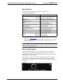
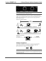
Crestron C2ENET-1/-2 2-Series Ethernet Interface Expansion Card Operations & Installation Guide This document was prepared and written by the Technical Documentation department at: Crestron Electronics, Inc. 15 Volvo Drive Rockleigh, NJ 07647 1-888-CRESTRON All brand names, product names and trademarks are the property of their respective owners. ©2004 Crestron Electronics, Inc. Crestron C2ENET-1/-2 2-Series Ethernet Interface Expansion Cards Contents 2-Series Ethernet Interface Expansion Cards: C2ENET-1 & C2ENET-2 1 Introduction ............................................................................................................................... 1 Features and Functions ................................................................................................ 1 Specifications .............................................................................................................. 2 Physical Description.................................................................................................... 2 Industry Compliance ................................................................................................... 3 Ethernet Cable Connections....................................................................................................... 4 Setup .......................................................................................................................................... 5 Installation ................................................................................................................... 5 IP Setup ....................................................................................................................... 6 Verify Communication.............................................................................................. 11 Setting a Control System Ethernet Password ............................................................ 12 Network Address Translation for Crestron 2-Series Control Systems ...................... 13 Enabling the C2ENET Card for e-Control® 2 ........................................................... 13 Programming Software ............................................................................................................ 14 Programming with SIMPL Windows ........................................................................ 14 TCP/IP Client and TCP/IP Server Symbols .............................................................. 16 Programming with VT Pro-e ..................................................................................... 18 Uploading Web pages................................................................................................ 18 Problem Solving ...................................................................................................................... 19 Troubleshooting......................................................................................................... 19 Further Inquiries ........................................................................................................ 20 Firmware Upgrades ................................................................................................... 20 Future Updates .......................................................................................................... 20 Software License Agreement................................................................................................... 21 Return and Warranty Policies .................................................................................................. 23 Merchandise Returns / Repair Service ...................................................................... 23 CRESTRON Limited Warranty................................................................................. 23 Glossary of Terms Operations & Installation Guide – DOC. 5962B 24 Contents • i Crestron C2ENET-1/-2 2-Series Ethernet Interface Expansion Cards 2-Series Ethernet Interface Expansion Cards: C2ENET-1 & C2ENET-2 Introduction Features and Functions The 2-Series Ethernet Interface Expansion Cards, C2ENET-1 and C2ENET-2, are 10/100 BaseT half/full duplex Ethernet cards designed for use in the Z-bus slot of Crestron’s AV2, PAC2, PRO2, and RACK2 2-Series control systems. The C2ENET-1 is a single-port WAN/LAN card, while the C2ENET-2 is a dual-port WAN/LAN card that, once installed, activates a control system's built-in firewall, router and network address translator (NAT). Either card allows for remote diagnostics and upgrades, access to Crestron’s network analyzer, and the ability to activate any device connected to a local control system via the Internet/Intranet. Throughout this guide, all references to C2ENET-1/-2 apply to both versions except where noted. As part of Crestron e-Control®, the C2ENET-1/-2 allows Internet communications to a control system. Web pages created in VisionTools® Pro-e (VT Pro-e) or other web page development tools can be uploaded and stored in the control system’s file system. Refer to the latest version of the 2-Series Control System Reference Guide, (Doc. 6256) for more information. The C2ENET-1/-2 allows up to 30 IP connections to simultaneously communicate with a control system. A control system can be accessed through the World Wide Web using the Microsoft® Internet Explorer browser. For a Crestron e-Control demonstration, go to www.crestron-econtrol.com. Further information and additional Crestron e-Control software can be obtained from the Software Updates section (e-Control subsection) of Crestron’s website (www.crestron.com). Functional Summary • • • • Operations & Installation Guide – DOC. 5962B 10/100 BaseT half/full duplex design High-speed Ethernet connectivity Dual LAN/WAN ports in C2ENET-2 Supports all Internet Protocols 2-Series Ethernet Interface Expansion Cards: C2ENET-1 & C2ENET-2 • 1 2-Series Ethernet Interface Expansion Cards Crestron C2ENET-1/-2 Specifications The following table provides specifications for the C2ENET-1/-2. Specifications of the C2ENET-1/-2 SPECIFICATION Power Requirements: DETAILS C2ENET-1 2 Watts (0.083 amps @ 24 VDC) C2ENET-2 3 Watts (0.125 amps @ 24 VDC) 10/100BaseT, half or full duplex TCP/IP, UDP/IP, ICMP (Ping), & HTTP Network Type Protocols SIMPL™ Windows® VT Pro-e 3 2-Series Control System Update File Internet Explorer Netscape Navigator IP Address Configuration Dimensions Weight: 1. 2. 1 Version 2.00 or later 1, 2 Version 2.3.3.1 or later 4 Version C2-1001.CUZ or later Version 4.0 or later Version 4.5 or later Static and dynamic addressing Height: 0.98 in (2.49 cm) Width: 4.28 in (10.86 cm) Depth: 4.71 in (11.95 cm) C2ENET-1 2.40 oz (0.07 kg) C2ENET-2 2.60 oz (0.08 kg) The latest software versions can be obtained from the Downloads | Software Updates section of the Crestron website (www.crestron.com). Crestron 2-Series control systems include the AV2 and PRO2. Consult the latest Crestron Product Catalog for a complete list of 2-Series control systems that are Ethernet-enabled directly or via a C2ENET-1/-2 Ethernet card. NOTE: Crestron software and any files on the website are for Authorized Crestron dealers only. New users may be required to register to obtain access to certain areas of the site (including the FTP site). Physical Description The C2ENET-1 and C2ENET-2 (refer to graphics below and on next page) are printed circuit boards (PCBs) fastened to aluminum faceplates. The cards are designed to be installed in a Z-BUS expansion slot on the 2-Series control systems. Two thumbscrews secure the cards. The C2ENET-1 contains one 8-wire RJ-45 Ethernet/LAN port. The C2ENET-2 contains two 8-wire RJ-45 ports (LAN A and LAN B). The port(s) is used for connection using an Ethernet cable (refer to cable connection example on page 4) to the Ethernet. C2ENET-1 2 • 2-Series Ethernet Interface Expansion Cards: C2ENET-1 & C2ENET-2 Operations & Installation Guide – DOC. 5962B Crestron C2ENET-1/-2 2-Series Ethernet Interface Expansion Cards C2ENET-2 NOTE: When the C2ENET-2 is used as a router, the WAN must be connected to LAN A and the LAN must be connected to LAN B. As shown in the illustration below, the port(s) contains two light-emitting diodes (LEDs). The green LED in the upper-left corner of the port(s) illuminates when it is connected to a working Ethernet. The yellow LED in the upper-right flashes to indicate Ethernet activity. C2ENET-1 & C2ENET-2 Faceplates 4.28 in (10.86 cm) LAN A 0.98 in (2.49 cm) C2ENET-1 ETHERNET INTERFACE LAN A LAN B 0.98 in (2.49 cm) C2ENET-2 ETHERNET INTERFACE C2ENET-1/-2 Port Indicators ETHERNET ACTIVITY LED (YELLOW) LINK STATUS LED (GREEN) Industry Compliance As of the date of manufacture, the C2ENET-1/-2 has been tested and found to comply with specifications for CE marking and standards per EMC and Radiocommunications Compliance Labelling (N11785). NOTE: This device complies with part 15 of the FCC rules. Operation is subject to the following two conditions: (1) this device may not cause harmful interference, and (2) this device must accept any interference received, including interference that may cause undesired operation. Operations & Installation Guide – DOC. 5962B 2-Series Ethernet Interface Expansion Cards: C2ENET-1 & C2ENET-2 • 3 2-Series Ethernet Interface Expansion Cards Crestron C2ENET-1/-2 Ethernet Cable Connections The following illustrates connection examples using a straight-through or crossover Ethernet cable. Ethernet Cable Connection Example N I C Ethernet Straight-through Cable Hub Ethernet Straight-through Cable C 2 E Crestron Control PC LAN Connection Example NIC - Network Inteface Card C2E - C2ENET-1/-2 PC N I C Ethernet Crossover Cable C 2 E Crestron Control Local Connection Example Connection to LAN If the control system is connected to a larger network via a hub, make sure that a straight (non-crossover type) Ethernet cable is used and that the cable is not connected to the UPLINK port of an Ethernet hub. Connection to PC If the system is connected directly to a personal computer (PC) Ethernet card, make sure that the cable between the C2ENET-1/-2 is a crossover type. RJ-45 Pinouts The following illustrates pinouts for a straight through and crossover RJ-45 Ethernet cables. Pins 4, 5, 7 and 8 are not used. RJ-45 Pinouts 4 • 2-Series Ethernet Interface Expansion Cards: C2ENET-1 & C2ENET-2 Operations & Installation Guide – DOC. 5962B Crestron C2ENET-1/-2 2-Series Ethernet Interface Expansion Cards Setup This section contains hardware installation and IP setup instructions for the C2ENET-1/-2. Required Tools/Hardware #1 Phillips screwdriver Grounding strap (recommended) Straight-through RS 232 cable with a male DB9 connector and a female DB9 connector PC with Viewport installed and open Crestron Control System Ethernet cable (straight thru or crossover) Installation CAUTION: The C2ENET-1/-2 and the control system contain electro-static discharge (ESD) sensitive devices. Crestron recommends that you wear a grounding strap to avoid damaging the card and/or the control system. 1. Disconnect power and Cresnet cables from the control system. 2. At the control system rear panel, remove the Z-BUS expansion slot blank faceplate. Refer to the following three examples. AV2 (AV2 with Card Cage & PRO2 Similar) Z-BUS Expansion Slot Example S8 Z-BUS PAC2 Z-BUS Expansion Slot Example S3 Z-BUS Operations & Installation Guide – DOC. 5962B 2-Series Ethernet Interface Expansion Cards: C2ENET-1 & C2ENET-2 • 5 2-Series Ethernet Interface Expansion Cards Crestron C2ENET-1/-2 RACK2 Z-BUS Expansion Slot (Slot 1 shown) Example 3. Remove the Ethernet card from its packaging. 4. On the Ethernet card, make sure the thumbscrews are extended outward, align the card with the card guides in the open Z-BUS expansion slot, and slide the card into slot. 5. Firmly press both ends of the card faceplate to seat it on the Z-BUS connector. CAUTION: DO NOT FORCE CARD IN SLOT. 6. Tighten the thumbscrews to finger-tight to secure the card. 7. Reapply power and connect the Cresnet and Ethernet cables. IP Setup This section provides step-by-step instructions to configure a control system to communicate over Ethernet using standard static IP configurations. The following illustration shows a simplified example of a possible IP setup. The control system and router are assigned IP numbers using Viewport. The external router is not configured using Viewport. IP Setup Detail of C2ENET-1 and C2ENET-2 Ethernet configuration Internet/ Intranet To/From Crestron IP Network (C2ENET-2) Hub To/From DSL Router via Hub To/From Crestron IP Network A B C2ENET2 To/From DSL Router via Hub DSL Router C2ENET-1/-2 Control System Default Router Static IP Number(s) assigned in Viewport 6 • 2-Series Ethernet Interface Expansion Cards: C2ENET-1 & C2ENET-2 A C2ENET1 Operations & Installation Guide – DOC. 5962B Crestron C2ENET-1/-2 2-Series Ethernet Interface Expansion Cards For Static IP Addressing The following instructions assume that the C2ENET-1/-2 is installed, Viewport is open on the PC, and the control system is powered up. NOTE: If the PC has a DB25 male connector, obtain a DB9 to DB25 adapter (the adapter has a DB9 male end and a DB25 female end). NOTE: For laptops and other PCs without a built-in RS-232 port, Crestron recommends the use of PCMCIA cards, rather than USB-to-serial adapters. If a USB-to-serial adapter must be used, Crestron has tested the following devices: Belkin (large model) F5U103 Belkin (small model) F5U409 I/O Gear GUC232A (discontinued) Keyspan USA-19QW (discontinued) Results may vary, depending on the computer being used. Other models, even from the same manufacturer, may not yield the same results. 1. Use the appropriate cable to connect the RS 232 COMPUTER port of the control system and the serial port of the PC. NOTE: It is assumed that your PC is communicating with the control system and the appropriate update file has been loaded. 2. Obtain appropriate control system static IP and router addresses from the/your network administrator. NOTE: The next three steps have you verify that the static IP address is not being used by another device. 3. On the PC, select Start | Run from the Taskbar to open the “Run” window. 4. Type command in the Open field and click OK. A DOS window appears. 5. At the prompt, type PING and the IP number. Press Enter. Example: PING 192.168.1.102 NOTE: Make sure you put a space between PING and the IP number. NOTE: If the system shows a “Request timed out”, go to step 6. If the system shows a “Reply from” with a time, the IP number is already in use. Obtain another IP number and repeat step 5. 6. Operations & Installation Guide – DOC. 5962B Open the Crestron Viewport and select Functions | Set Control System IP Information from the main menu. The “Ethernet Configuration” window opens (refer to following graphics). 2-Series Ethernet Interface Expansion Cards: C2ENET-1 & C2ENET-2 • 7 2-Series Ethernet Interface Expansion Cards Crestron C2ENET-1/-2 Set Control System IP Information “Ethernet Configuration” Window In the above example, the control system is set to the IP address 192.168.1.5. The subnet mask is the default for that address class (Class C), 255.255.255.0, and the default router address is set to 0.0.0.0. Static values can be set for the LAN B side of the C2ENET-2 card the same way. Simply select LAN B from the Ethernet Adapter list. The C2ENET-2 card allows you to create a sub-network within a larger corporate or residential LAN. Here, LAN A is the public side that is visible to users on the larger network, while LAN B is the internal LAN of e-Control devices. In this way, a network administrator would need to provide one static IP address for the public (LAN A) side. Alternatively, the LAN A side can be configured for dynamic IP addressing. When assigning an IP address for LAN B, it is recommended that you choose from the private IP address classes. The network addresses of LAN A and LAN B cannot be the same. For example, if the same subnet mask is applied to both IP addresses and the resulting network 8 • 2-Series Ethernet Interface Expansion Cards: C2ENET-1 & C2ENET-2 Operations & Installation Guide – DOC. 5962B Crestron C2ENET-1/-2 2-Series Ethernet Interface Expansion Cards address is 192.168.1.0, then an error message will be generated. Refer to the “eControl Hardware Configuration” section within the latest version of the Crestron e-Control® Reference Guide (Doc. 6052) for more information. For Dynamic IP Addressing 1. Select the Enable DHCP check box to enable DHCP with a Windows 2000/3000 Server; for a Windows NT 4.0 Server, select both the Enable DHCP and the Enable WINS check boxes. The IP Address and IP Mask fields will be ignored if either check box is selected. (Refer to VT Pro-e online help for more information on DHCP settings.) 2. Enter the hostname of the control system in the Hostname field. The hostname identifies the machine on the network and is automatically translated into the numerical IP address. The hostname can consist of up to 64 characters. Valid characters are 0 – 9, A – Z (not case sensitive), and the dash (hyphen character). No other characters are valid. The hostname cannot begin with a dash or number. 3. The IP address of the default router is provided by the DHCP server and thus the Default Router field should be left blank. “Ethernet Configuration” Window If applicable, enter the domain in the Domain field. This is necessary only if you are configuring DHCP on an Ethernet connection to a control system that currently has a static address. The domain name will be used to reconnect to the control system after it reboots. With a serial connection, the domain does not need to be entered. NOTE: The domain supplied by the DHCP server will overwrite the domain that is indicated in this field. Advanced Settings (optional): 1. Operations & Installation Guide – DOC. 5962B Click the Advanced button to set optional parameters. (Refer to the figure on the next page.) You can enter the IP address of the primary DNS server in the DNS Server 1 field; enter the IP address of the secondary DNS Server in field 2. 2-Series Ethernet Interface Expansion Cards: C2ENET-1 & C2ENET-2 • 9 2-Series Ethernet Interface Expansion Cards Crestron C2ENET-1/-2 If the DHCP server provides the address for the DNS server, it is not necessary to enter these values. Here the DNS server addresses will automatically be filled in. 2. You have the option to change the CIP and CTP port numbers in rare cases where a network conflict may exist with ports 41794 and 41795. The Web port can be changed for security reasons if no firewall or router is protecting the network. To prevent attacks by hackers the port can be moved to another value. Users on the LAN would then have to specify the port number in the URL, i.e., http//www.crestron.com:49153 where the value after the colon indicates the Web port. In most cases, the port numbers do not need to be changed. “Ethernet Configuration” Advanced Settings Window 3. The Enable Web Server check box turns the Web server on and off. 4. When you are satisfied with the IP settings click OK to reboot the control system. Once you have set the IP information for the control system, it becomes possible to communicate with the console via TCP/IP. Click Communication Settings on the Viewport Setup menu and choose TCP/IP as the connection type. Then enter the IP address or fully qualified domain name of the control system. 10 • 2-Series Ethernet Interface Expansion Cards: C2ENET-1 & C2ENET-2 Operations & Installation Guide – DOC. 5962B Crestron C2ENET-1/-2 2-Series Ethernet Interface Expansion Cards The Viewport title bar will display the new communication settings, e.g., “Connected to ConferenceRoom.com on Port 41795.” For information on secure sockets layer (SSL) configuration, refer to the latest versions of the Crestron 2-Series Control Systems Reference Guide (Doc. 6256), and the Crestron e-Control Reference Guide (Doc. 6052). They may be downloaded from the Downloads | Product Manuals | Software section of the Crestron website (www.crestron.com). Verify Communication 1. To verify the C2ENET card communication, open Viewport on your PC and select Remote | TCP/IP | Connect from the Taskbar. The “Crestron Viewport TCP/IP Connect” window appears. Crestron Viewport TCP/IP Connect 2. Enter the IP number you entered earlier and click Connect. The Crestron Viewport confirms the connection. Crestron Viewport TCP/IP Confirmation NOTE: If the following Error window opens, verify IP address and repeat steps 1 and 2. Operations & Installation Guide – DOC. 5962B 2-Series Ethernet Interface Expansion Cards: C2ENET-1 & C2ENET-2 • 11 2-Series Ethernet Interface Expansion Cards Crestron C2ENET-1/-2 Error Window Setting a Control System Ethernet Password After establishing communication with a control system via Ethernet, the Viewport may be used to set (or change) a password to limit access to the control system. NOTE: The Ethernet password protects console communications (file transfer, diagnostics, etc.), it does not prevent users from browsing web pages. Do the following to set a password: 1. In Viewport, select Functions | Set TCP/IP Console Password. The “Enter New Password” window opens (refer to subsequent graphic). Viewport Set TCP/IP Control Password option 2. Enter and verify a new password and click OK. “Enter New Password” Window 12 • 2-Series Ethernet Interface Expansion Cards: C2ENET-1 & C2ENET-2 Operations & Installation Guide – DOC. 5962B Crestron C2ENET-1/-2 2-Series Ethernet Interface Expansion Cards Network Address Translation for Crestron 2-Series Control Systems Network Address Translation (NAT) is a method of connecting multiple computers on an internal network to the Internet (or any other IP network) using one publicly visible IP address. Current implementation for the Crestron 2-Series control systems includes a combination of the Network Address Port Translator protocol (NAPT) and Bi-Directional NAT. NAT functionality is included in the firmware of Crestron 2-Series control processors, and enabled through a dual port Ethernet Z-bus expansion card (C2ENET-2 only). For specific details on NAT, including setup and configuration, refer to the latest version of Doc. 6001, Crestron Network Address Translator (NAT) Reference Guide. It is available from the Downloads | Product Manuals | Miscellaneous section of the Crestron website (www.crestron.com). Enabling the C2ENET Card for e-Control® 2 You must be licensed to use e-Control 2, but the process is simple. * 1. With your PC connected to the control system, open the Viewport and verify communication as described in “Verify Communication” on page 11. 2. From the Viewport menu, select Functions | e-Control 2 Activation. The system displays the “e-Control 2 Activation” window. As stated on the screen, submit the displayed Ethernet Card Code to Crestron customer service. 3. Activate e-Control 2 by entering the activation code received from customer service in the Activation Code: field and pressing Activate. “e-Control 2 Activation” Window * This applies only to e-Control projects for XPanel PPC and XPanel HPC. Operations & Installation Guide – DOC. 5962B 2-Series Ethernet Interface Expansion Cards: C2ENET-1 & C2ENET-2 • 13 2-Series Ethernet Interface Expansion Cards Crestron C2ENET-1/-2 Programming Software Have a question or comment about Crestron software? Answers to frequently asked questions (FAQs) can be viewed in the Online Help section of the Crestron website (www.crestron.com). To post your own question or view questions you have submitted to Crestron’s True Blue Support, log in at http://www.crestron.com/accounts/login.asp. First-time users will need to establish a user account. You can create a program that allows you to control a network device through a Crestron control system via a C2ENET-1/-2 card using the Crestron programming tool SIMPL Windows. The following are minimum software version requirements for the PC: • SIMPL Windows version 2.01.06, or later. Requires SIMPL+ Cross Compiler version 1.1. • VT Pro-e version 2.4 or later. • Crestron Database version 15.7.3 or later. Programming with SIMPL Windows NOTE: The following assumes that the reader has knowledge of SIMPL Windows. If not, refer to the extensive help information provided with the software. NOTE: In the following description, the PRO2 control system and the C2ENET-2 are used. SIMPL Windows is Crestron's software for programming Crestron control systems. It provides a well-designed graphical environment with a number of workspaces (i.e., windows) in which a programmer can select, configure, program, test, and monitor a Crestron control system. SIMPL Windows offers drag and drop functionality in a familiar Windows environment. This section explains how to create a SIMPL Windows program that includes a C2ENET-1/-2. Configuration Manager is where programmers “build” a Crestron control system by selecting hardware from the Device Library. In Configuration Manager, drag the PRO2 from the Control Systems folder of the Device Library and drop it in the upper pane of the System Views. The PRO2 with its associated communication ports is displayed in the System Views upper pane. PRO2 System View 14 • 2-Series Ethernet Interface Expansion Cards: C2ENET-1 & C2ENET-2 Operations & Installation Guide – DOC. 5962B Crestron C2ENET-1/-2 2-Series Ethernet Interface Expansion Cards The System Views lower pane displays the PRO2 system tree. This tree can be expanded to display and configure the various slots. Expanded PRO2 System Tree C2Z Card Slot in Configuration Manager The C2Z Card Slot can accept a C2ENET-2, which enables the PRO2 to address up to 252 Ethernet devices. Each Ethernet device is assigned a unique identifier called an IP ID, which is a hexadecimal value ranging from 03 to FE. In Configuration Manager, drag a C2ENET-2 from the Plug-in Control Cards | Cards (2-Series Z Bus) folder of the Device Library and drop it on the PRO2 C2Z Card Slot in System Views. The System Views upper pane displays the Ethernet Units icon below the PRO2 graphic. To view the list of supported devices, expand the control system in the bottom pane of System Views and double-click Slot 8: C2ENET-2. Supported devices include Ethernet control modules, PC and Web browser interfaces, and a variety of Crestron Ethernet touchpanels. To add a device to the system, expand the slot and doubleclick the desired IP ID, or right-click and select Add Item from the submenu. Then select the device you want to add. In Program Manager, the C2ENET-2 symbol contains no signals; to program a controlled Ethernet device, expand the C2ENET-2 symbol in Program View. Then drag the symbol to Detail View. (Alternatively, you can double-click the symbol.) About the IP Table For the PRO2 (or any Ethernet-enabled control system) to control devices via Ethernet, the IP ID (all Cresnet devices are assigned IP IDs) of the device must be associated with an IP address, and both the IP ID and IP address must be entered into the IP table of the control system. You can create an IP table in two ways. The first method is to double-click the device in Configuration Manager to open the “Device Settings” window. Click the IP Net Address tab and enter the IP address of the device in the IP Address field. Repeat this procedure for all Ethernet devices in your system. This creates what is referred to as a “default” IP table. When the program is compiled and ready to be uploaded to the control system, you will have the option to upload this default IP table. The second method is to use the Crestron Viewport. This method is especially useful on site if you want to change one or more IP addresses without changing the program. Alternatively, as with all 2-Series control systems, the PRO2 also has the capability to function as a peripheral device, or “slave”, in a master/slave arrangement with Operations & Installation Guide – DOC. 5962B 2-Series Ethernet Interface Expansion Cards: C2ENET-1 & C2ENET-2 • 15 2-Series Ethernet Interface Expansion Cards Crestron C2ENET-1/-2 another control system. Here the IP table of the PRO2 must contain just one entry for the master control system. Refer to the “Creating an IP Table” section within the latest version of the Crestron e-Control® Reference Guide (Doc. 6052) for more information. Example Program An example program for the C2ENET-1/2 is available from the Crestron website (www.crestron.com). Select Downloads | Example Programs | Miscellaneous | eControl 2. Uploading a Program Refer to a 2-Series control system document for uploading information. TCP/IP Client and TCP/IP Server Symbols In typical TCP/IP Terminology, a client connects to a server. Our server symbol can handle only one connection to it. Since the sockets are generic TCP/IP, the client can connect to any server (Crestron's TCP/IP Server symbol or any non-Crestron server) and the server can accept a connection from any client (Crestron's TCP/IP Client symbol or any non-Crestron client). The server symbol “listens” for a connection on a particular socket, and a client symbol is capable of connecting or disconnecting a socket. A socket is comprised of an IP address and a port number. The IP address is specified in the IP table on the IP ID where the symbol resides and the port number is specified in the symbol. For example, if the server symbol is dropped on IP ID 15, and the IP table entry for IP ID 15 is 192.168.1.1, the server will listen for a connection from a 192.168.1.1 on the port number specified in the symbol. NOTE: An IP address entry of 0.0.0.0 allows connection from any IP address. If the IP table contains valid IP addresses, connection will be allowed only from the specified addresses. The following diagrams show the TCP/IP Client and the TCP/IP Server symbols in SIMPL Windows. Detail View of the TCP/IP Client Symbol in SIMPL Windows’ Programming Manager The TCP/IP Client symbol enables TCP/IP communication between the control system and a device that has a TCP/IP port. The symbol must be assigned the IP address of the device, while the port address of the device must be entered in the <Port> parameter of the symbol. Both the IP address and port should be found in the manufacturer's documentation. The symbol initiates the connection on the rising edge of <Connect>; when communication is established, <Connect-F> goes high. Serial data can then be 16 • 2-Series Ethernet Interface Expansion Cards: C2ENET-1 & C2ENET-2 Operations & Installation Guide – DOC. 5962B Crestron C2ENET-1/-2 2-Series Ethernet Interface Expansion Cards transmitted and received via <TX$> (transmit) and <RX$> (receive) for as long as <Connect-F> remains high. The <status> output is used for diagnostics and reports the connection status. The valid values are shown in the following table: Analog Value Connection Status 0 Not connected 1 Waiting for connection 2 Connected 3 Connection failed 4 Connection broken remotely 5 Connection broken locally 6 Performing DNS lookup 7 DNS lookup failed The TCP/IP Client symbol differs from the TCP/IP Server symbol (refer to graphic below) in that the Server symbol can only listen for a connection from a device, whereas the Client symbol can initiate the connection. Detail View of the TCP/IP Server Symbol in SIMPL Windows’ Programming Manager The TCP/IP Server symbol enables TCP/IP communication between any device with a TCP/IP port and the control system. It differs from the TCP/IP Client symbol in that the latter symbol can initiate a connection with a device, whereas the TCP/IP Server symbol can only listen for a connection. The symbol must be assigned the IP address of the device, while the port address of the device must be entered in the <Port> parameter of the symbol. Both the IP address and port should be provided by the manufacturer's documentation. When the device establishes communication with the symbol, the <Connect-F> output goes high. Serial data can then be transferred via <TX$> (transmit) and <RX$> (receive) for as long as <Connect-F> remains high. The <status> output is used for diagnostics and reports the connection status. The valid values are the same as those shown in the previous table. The optional <enable> input has a default value of 1. If <enable> is defined and goes low, no connection can be established (and <status> will equal 0). Operations & Installation Guide – DOC. 5962B 2-Series Ethernet Interface Expansion Cards: C2ENET-1 & C2ENET-2 • 17 2-Series Ethernet Interface Expansion Cards Crestron C2ENET-1/-2 Programming with VT Pro-e Information on creating web pages using VT Pro-e is in the VT Pro-e help file under the section “Web Browser Projects.” For e-Control projects: When an e-Control browser project is created, VT Pro-e automatically creates a folder with the name of the project and a .web extension. This web project folder itself contains a Java subfolder, in addition to all the HTML files that are sent to the MP2E. In VT Pro-e, the target type is BROWSER. For e-Control 2 projects: When an e-Control 2 project is created, VT Pro-e automatically creates a folder with the name of the project and a .xweb extension. The web project folder contains all the necessary e-Control 2 files. In VT Pro-e, the target type is XPANEL. In designing and creating a browser project, keep in mind that you must assign an IP ID to all the project pages and specify the IP address of the control system. (For further information on this procedure, refer to the VT Pro-e online help file.) Uploading Web pages The AV2/PRO2 provides a built-in Web server for e-Control applications. The AV2/PRO2 allots 2.5 MB of memory for “user files” such as Web pages, mailbox, and the compiled SPZ file. Web pages are loaded in the AV2/PRO2 using Viewport. Refer to the “Uploading Web Pages” section within the latest version of the Crestron e-Control® Reference Guide (Doc. 6052) for more information. 18 • 2-Series Ethernet Interface Expansion Cards: C2ENET-1 & C2ENET-2 Operations & Installation Guide – DOC. 5962B Crestron C2ENET-1/-2 2-Series Ethernet Interface Expansion Cards Problem Solving Troubleshooting The table below provides corrective action for possible trouble situations. If further assistance is required, please contact a Crestron customer service representative. C2ENET-1/-2 Troubleshooting Trouble Communications via the LAN port is not functioning. Probable Cause(s) Corrective Action C2ENET-1/-2 improperly installed. Follow installation procedures in this guide. Improper Ethernet connection. Verify proper connection at Ethernet port. Damaged connector pins. Follow installation procedures in this guide and inspect connector pins. Incorrect firmware/software. Update firmware/software versions per the specifications in this guide. Another device on the LAN has the same/conflicting IP address. Disconnect NET/IP cable from the control system. Ping the IP address of the control system. If a reply occurs, obtain a new static IP address for the control system. Conflicting IP address window opens after entering IP addresses in new IP address fields. IP Subnet for LAN A and LAN B match (C2ENET2 only). Change LAN B IP address so that WAN and LAN no longer conflict. Objects on Web page do not draw correctly. File transfer error. Reload Web page project. Cannot communicate with control system through router. Appropriate port not open through router. Verify port 80 is open for Web hosting. Verify port 41795 is open for Crestron diagnostics. Verify port 41794 is open for CIP. Control system runs slow or crashes on LAN. Potential virus on Web port 80. Operations & Installation Guide – DOC. 5962B Change Web port via Viewport using console commands, or click the Advanced button in the Ethernet Configuration window. (Refer to “Advanced Settings (optional): on page 9 of this guide. 2-Series Ethernet Interface Expansion Cards: C2ENET-1 & C2ENET-2 • 19 2-Series Ethernet Interface Expansion Cards Crestron C2ENET-1/-2 Further Inquiries If after reviewing this Operations and Installation Guide, you cannot locate specific information or have questions, please take advantage of Crestron's award winning customer service team by calling: • In the US and Canada, call Crestron’s corporate headquarters at 1-888-CRESTRON [1-888-273-7876]. • In Europe, call Crestron International at +32-15-50-99-50. • In Asia, call Crestron Asia at +852-2341-2016. • In Latin America, call Crestron Latin America at +5255-5093-2160. • In Australia and New Zealand, call Crestron Control Solutions at +61-2-9737-8203. Firmware Upgrades To take advantage of all the C2ENET’s features, it is important that the unit contains the latest firmware available. Therefore, please check Crestron’s website (http://www.crestron.com/downloads/software_updates.asp) for the latest version of firmware. Not every product has a firmware upgrade, but as Crestron improves functions, adds new features, and extends the capabilities of its products, firmware upgrades are posted. If you have questions regarding upgrades procedures, contact Crestron customer service. Future Updates As Crestron improves functions, adds new features, and extends the capabilities of the C2ENET-1/-2, additional information may be made available as manual updates. These updates are solely electronic and serve as intermediary supplements prior to the release of a complete technical documentation revision. Check the Crestron website (www.crestron.com) periodically for manual update availability and its relevance. Updates are available from the Download | Product Manuals section and are identified as an “Addendum” in the Download column. 20 • 2-Series Ethernet Interface Expansion Cards: C2ENET-1 & C2ENET-2 Operations & Installation Guide – DOC. 5962B Crestron C2ENET-1/-2 2-Series Ethernet Interface Expansion Cards Software License Agreement This License Agreement (“Agreement”) is a legal contract between you (either an individual or a single business entity) and Crestron Electronics, Inc. (“Crestron”) for software referenced in this guide, which includes computer software and, as applicable, associated media, printed materials, and “online” or electronic documentation (the “Software”). BY INSTALLING, COPYING, OR OTHERWISE USING THE SOFTWARE, YOU REPRESENT THAT YOU ARE AN AUTHORIZED DEALER OF CRESTRON PRODUCTS OR A CRESTRON AUTHORIZED INDEPENDENT PROGRAMMER AND YOU AGREE TO BE BOUND BY THE TERMS OF THIS AGREEMENT. IF YOU DO NOT AGREE TO THE TERMS OF THIS AGREEMENT, DO NOT INSTALL OR USE THE SOFTWARE. IF YOU HAVE PAID A FEE FOR THIS LICENSE AND DO NOT ACCEPT THE TERMS OF THIS AGREEMENT, CRESTRON WILL REFUND THE FEE TO YOU PROVIDED YOU (1) CLICK THE DO NOT ACCEPT BUTTON, (2) DO NOT INSTALL THE SOFTWARE AND (3) RETURN ALL SOFTWARE, MEDIA AND OTHER DOCUMENTATION AND MATERIALS PROVIDED WITH THE SOFTWARE TO CRESTRON AT: CRESTRON ELECTRONICS, INC., 15 VOLVO DRIVE, ROCKLEIGH, NEW JERSEY 07647, WITHIN 30 DAYS OF PAYMENT. LICENSE TERMS Crestron hereby grants You and You accept a nonexclusive, nontransferable license to use the Software (a) in machine readable object code together with the related explanatory written materials provided by Crestron (b) on a central processing unit (“CPU”) owned or leased or otherwise controlled exclusively by You, and (c) only as authorized in this Agreement and the related explanatory files and written materials provided by Crestron. If this software requires payment for a license, you may make one backup copy of the Software, provided Your backup copy is not installed or used on any CPU. You may not transfer the rights of this Agreement to a backup copy unless the installed copy of the Software is destroyed or otherwise inoperable and You transfer all rights in the Software. You may not transfer the license granted pursuant to this Agreement or assign this Agreement without the express written consent of Crestron. If this software requires payment for a license, the total number of CPU’s on which all versions of the Software are installed may not exceed one per license fee (1) and no concurrent, server or network use of the Software (including any permitted back-up copies) is permitted, including but not limited to using the Software (a) either directly or through commands, data or instructions from or to another computer (b) for local, campus or wide area network, internet or web hosting services; or (c) pursuant to any rental, sharing or “service bureau” arrangement. The Software is designed as a software development and customization tool. As such Crestron cannot and does not guarantee any results of use of the Software or that the Software will operate error free and You acknowledge that any development that You perform using the Software or Host Application is done entirely at Your own risk. The Software is licensed and not sold. Crestron retains ownership of the Software and all copies of the Software and reserves all rights not expressly granted in writing. OTHER LIMITATIONS You must be an Authorized Dealer of Crestron products or a Crestron Authorized Independent Programmer to install or use the Software. If Your status as a Crestron Authorized Dealer or Crestron Authorized Independent Programmer is terminated, Your license is also terminated. You may not rent, lease, lend, sublicense, distribute or otherwise transfer or assign any interest in or to the Software. You may not reverse engineer, decompile, or disassemble the Software. You agree that the Software will not be shipped, transferred or exported into any country or used in any manner prohibited by the United States Export Administration Act or any other export laws, restrictions or regulations (“Export Laws”). By downloading or installing the Software You (a) are certifying that You are not a national of Cuba, Iran, Iraq, Libya, North Korea, Sudan, or Syria or any country to which the United States embargoes goods (b) are certifying that You are not otherwise prohibited from receiving the Software and (c) You agree to comply with the Export Laws. If any part of this Agreement is found void and unenforceable, it will not affect the validity of the balance of the Agreement, which shall remain valid and enforceable according to its terms. This Agreement may only be modified by a writing signed by an authorized officer of Crestron. Updates may be licensed to You by Crestron with additional or different terms. This is the entire agreement between Crestron and You relating to the Software and it supersedes any prior representations, discussions, undertakings, communications or advertising relating to the Software. The failure of either party to enforce any right or take any action in the event of a breach hereunder shall constitute a waiver unless expressly acknowledged and set forth in writing by the party alleged to have provided such waiver. Operations & Installation Guide – DOC. 5962B 2-Series Ethernet Interface Expansion Cards: C2ENET-1 & C2ENET-2 • 21 2-Series Ethernet Interface Expansion Cards Crestron C2ENET-1/-2 If You are a business or organization, You agree that upon request from Crestron or its authorized agent, You will within thirty (30) days fully document and certify that use of any and all Software at the time of the request is in conformity with Your valid licenses from Crestron of its authorized agent. Without prejudice to any other rights, Crestron may terminate this Agreement immediately upon notice if you fail to comply with the terms and conditions of this Agreement. In such event, you must destroy all copies of the Software and all of its component parts. PROPRIETARY RIGHTS Copyright. All title and copyrights in and to the Software (including, without limitation, any images, photographs, animations, video, audio, music, text, and “applets” incorporated into the Software), the accompanying media and printed materials, and any copies of the Software are owned by Crestron or its suppliers. The Software is protected by copyright laws and international treaty provisions. Therefore, you must treat the Software like any other copyrighted material, subject to the provisions of this Agreement. Submissions. Should you decide to transmit to Crestron’s website by any means or by any media any materials or other information (including, without limitation, ideas, concepts or techniques for new or improved services and products), whether as information, feedback, data, questions, comments, suggestions or the like, you agree such submissions are unrestricted and shall be deemed non-confidential and you automatically grant Crestron and its assigns a non-exclusive, royalty-tree, worldwide, perpetual, irrevocable license, with the right to sublicense, to use, copy, transmit, distribute, create derivative works of, display and perform the same. Trademarks. CRESTRON and the Swirl Logo are registered trademarks of Crestron Electronics, Inc. You shall not remove or conceal any trademark or proprietary notice of Crestron from the Software including any back-up copy. GOVERNING LAW This Agreement shall be governed by the laws of the State of New Jersey, without regard to conflicts of laws principles. Any disputes between the parties to the Agreement shall be brought in the state courts in Bergen County, New Jersey or the federal courts located in the District of New Jersey. The United Nations Convention on Contracts for the International Sale of Goods, shall not apply to this Agreement. CRESTRON LIMITED WARRANTY CRESTRON warrants that: (a) the Software will perform substantially in accordance with the published specifications for a period of ninety (90) days from the date of receipt, and (b) that any hardware accompanying the Software will be subject to its own limited warranty as stated in its accompanying written material. Crestron shall, at its option, repair or replace or refund the license fee for any Software found defective by Crestron if notified by you within the warranty period. The foregoing remedy shall be your exclusive remedy for any claim or loss arising from the Software. CRESTRON shall not be liable to honor warranty terms if the product has been used in any application other than that for which it was intended, or if it as been subjected to misuse, accidental damage, modification, or improper installation procedures. Furthermore, this warranty does not cover any product that has had the serial number or license code altered, defaced, improperly obtained, or removed. Notwithstanding any agreement to maintain or correct errors or defects Crestron, shall have no obligation to service or correct any error or defect that is not reproducible by Crestron or is deemed in Crestron’s reasonable discretion to have resulted from (1) accident; unusual stress; neglect; misuse; failure of electric power, operation of the Software with other media not meeting or not maintained in accordance with the manufacturer’s specifications; or causes other than ordinary use; (2) improper installation by anyone other than Crestron or its authorized agents of the Software that deviates from any operating procedures established by Crestron in the material and files provided to You by Crestron or its authorized agent; (3) use of the Software on unauthorized hardware; or (4) modification of, alteration of, or additions to the Software undertaken by persons other than Crestron or Crestron’s authorized agents. ANY LIABILITY OF CRESTRON FOR A DEFECTIVE COPY OF THE SOFTWARE WILL BE LIMITED EXCLUSIVELY TO REPAIR OR REPLACEMENT OF YOUR COPY OF THE SOFTWARE WITH ANOTHER COPY OR REFUND OF THE INITIAL LICENSE FEE CRESTRON RECEIVED FROM YOU FOR THE DEFECTIVE COPY OF THE PRODUCT. THIS WARRANTY SHALL BE THE SOLE AND EXCLUSIVE REMEDY TO YOU. IN NO EVENT SHALL CRESTRON BE LIABLE FOR INCIDENTAL, CONSEQUENTIAL, SPECIAL OR PUNITIVE DAMAGES OF ANY KIND (PROPERTY OR ECONOMIC DAMAGES INCLUSIVE), EVEN IF A CRESTRON REPRESENTATIVE HAS BEEN ADVISED OF THE POSSIBILITY OF SUCH DAMAGES OR OF ANY CLAIM BY ANY THIRD PARTY. CRESTRON MAKES NO WARRANTIES, EXPRESS OR IMPLIED, AS TO TITLE OR INFRINGEMENT OF THIRD-PARTY RIGHTS, MERCHANTABILITY OR FITNESS FOR ANY PARTICULAR PURPOSE, OR ANY OTHER WARRANTIES, NOR AUTHORIZES ANY OTHER PARTY TO OFFER ANY WARRANTIES, INCLUDING WARRANTIES OF MERCHANTABILITY FOR THIS PRODUCT. THIS WARRANTY STATEMENT SUPERSEDES ALL PREVIOUS WARRANTIES. 22 • 2-Series Ethernet Interface Expansion Cards: C2ENET-1 & C2ENET-2 Operations & Installation Guide – DOC. 5962B Crestron C2ENET-1/-2 2-Series Ethernet Interface Expansion Cards Return and Warranty Policies Merchandise Returns / Repair Service 1. No merchandise may be returned for credit, exchange, or service without prior authorization from CRESTRON. To obtain warranty service for CRESTRON products, contact the factory and request an RMA (Return Merchandise Authorization) number. Enclose a note specifying the nature of the problem, name and phone number of contact person, RMA number, and return address. 2. Products may be returned for credit, exchange, or service with a CRESTRON Return Merchandise Authorization (RMA) number. Authorized returns must be shipped freight prepaid to CRESTRON, 6 Volvo Drive, Rockleigh, N.J., or its authorized subsidiaries, with RMA number clearly marked on the outside of all cartons. Shipments arriving freight collect or without an RMA number shall be subject to refusal. CRESTRON reserves the right in its sole and absolute discretion to charge a 15% restocking fee, plus shipping costs, on any products returned with an RMA. 3. Return freight charges following repair of items under warranty shall be paid by CRESTRON, shipping by standard ground carrier. In the event repairs are found to be non-warranty, return freight costs shall be paid by the purchaser. CRESTRON Limited Warranty CRESTRON ELECTRONICS, Inc. warrants its products to be free from manufacturing defects in materials and workmanship under normal use for a period of three (3) years from the date of purchase from CRESTRON, with the following exceptions: disk drives and any other moving or rotating mechanical parts, pan/tilt heads and power supplies are covered for a period of one (1) year; touchscreen display and overlay components are covered for 90 days; batteries and incandescent lamps are not covered. This warranty extends to products purchased directly from CRESTRON or an authorized CRESTRON dealer. Purchasers should inquire of the dealer regarding the nature and extent of the dealer's warranty, if any. CRESTRON shall not be liable to honor the terms of this warranty if the product has been used in any application other than that for which it was intended, or if it has been subjected to misuse, accidental damage, modification, or improper installation procedures. Furthermore, this warranty does not cover any product that has had the serial number altered, defaced, or removed. This warranty shall be the sole and exclusive remedy to the original purchaser. In no event shall CRESTRON be liable for incidental or consequential damages of any kind (property or economic damages inclusive) arising from the sale or use of this equipment. CRESTRON is not liable for any claim made by a third party or made by the purchaser for a third party. CRESTRON shall, at its option, repair or replace any product found defective, without charge for parts or labor. Repaired or replaced equipment and parts supplied under this warranty shall be covered only by the unexpired portion of the warranty. Except as expressly set forth in this warranty, CRESTRON makes no other warranties, expressed or implied, nor authorizes any other party to offer any warranty, including any implied warranties of merchantability or fitness for a particular purpose. Any implied warranties that may be imposed by law are limited to the terms of this limited warranty. This warranty statement supercedes all previous warranties. Trademark Information All brand names, product names, and trademarks are the sole property of their respective owners. Windows is a registered trademark of Microsoft Corporation. Windows95/98/Me/XP and WindowsNT/2000 are trademarks of Microsoft Corporation. Operations & Installation Guide – DOC. 5962B 2-Series Ethernet Interface Expansion Cards: C2ENET-1 & C2ENET-2 • 23 2-Series Ethernet Interface Expansion Cards Crestron C2ENET-1/-2 Glossary of Terms 2-SERIES CONTROL SYSTEM Crestron 2-Series control systems include the AV2 and PRO2. Consult the latest Crestron Product Catalog for a complete list of 2-Series control systems that are Ethernet-enabled directly or via a C2ENET-1/-2 Ethernet card. CRESNET ID Cresnet ID, a unique identity code ranging from 03 to FE (in hexadecimal), is given to all devices that communicate using the Cresnet network protocol. DEFAULT ROUTER A default router is a router that sends packets within the local network to destinations outside of the local network, or receives them from outside and propagates them onto the local network. It is also referred to as a Gateway. ETHERNET HUB Inexpensive four to 16 port devices that provide a way to physically tap into an existing Ethernet connection and expand the plugs available, but do not perform any packet routing. GATEWAY See Default Router above. IP ADDRESS Internet protocol address is a unique number that is used to represent every single computer in a network. All the computers on the Internet have a unique IP address. The format of the IP address is four numbers separated by dots (e.g., 198.123.456.7). IP ID The IP ID is a two-digit hexadecimal number that is used to differentiate a given device from a group of Ethernet devices in a control system with the same IP address. Just as the Net ID is used to distinguish between identical devices within a SIMPL Windows program, the IP address for a specific IP ID in the control system’s IP table must be set to the IP address of the given device. Furthermore, the IP ID in the given device’s static master table must be set to the IP address of the control system. IP TABLE An IP table lists IP IDs and their corresponding IP addresses. This table is maintained inside each control system, though it may be generated by a SIMPL Windows program, or edited manually using the Viewport utility. 24 • Glossary of Terms Operations & Installation Guide – DOC. 5962B Crestron C2ENET-1/-2 2-Series Ethernet Interface Expansion Cards NETWORK ADDRESS A network address is a pattern of bits in IP address format that is shared by all network devices on a given local network. For example, network address 192.168.2.0 describes the local network where all devices have an IP address of 192.168.2.x, where x is any value from 1 to 254. ROUTER Router is a communications device which routes data between networks. SUBNET MASK A mask simply conceals something. With respect to an IP address, a mask is simply a screen of numbers that reveals a set of numbers on which to focus. For example, consider the IP address 150.215.017.009. Assuming this is part of a Class B network, the first two numbers (150.215) represent the Class B network address, and the second two numbers (017.009) identify a particular host on this network. Therefore, the subnet mask is the network address plus the bits reserved for identifying the sub network. (By convention, the bits for the network address are all set to 1, though it would also work if the bits were set exactly as in the network address.) In this case, therefore, the subnet mask would be 11111111.11111111.11110000.00000000. It's called a mask because it can be used to identify the subnet to which an IP address belongs by performing a bitwise AND operation on the mask and the IP address. The result is the sub network address: Subnet Mask 255.255.240.000 11111111.11111111.11110000.00000000 IP Address 150.215.017.009 10010110.11010111.00010001.00001001 Subnet Address 150.215.016.000 10010110.11010111.00010000.00000000 The subnet address, therefore, is 150.215.016.000. TCP/IP TCP/IP is the acronym for Transmission Control Protocol/Internet Protocol. It is a standard set of protocols that govern the basic workings of the Internet that was implemented in 1982. The TCP part is all about ensuring that data is transmitted correctly between two computers. If any errors occur these are detected and the data is retransmitted. The data transmitted is split up into small portions referred to as data packets. The IP part of TCP/IP is how these data packets are moved from one point to another. Each computer on the Internet has a unique IP address and the data packets are moved from the source to the destination through many different computers that are controlled via TCP/IP. This protocol is used on the Internet and also by computers that are part of a LAN. Operations & Installation Guide – DOC. 5962B Glossary of Terms • 25 2-Series Ethernet Interface Expansion Cards Crestron C2ENET-1/-2 This page intentionally left blank. 26 • Glossary of Terms Operations & Installation Guide – DOC. 5962B Crestron C2ENET-1/-2 2-Series Ethernet Interface Expansion Cards This page intentionally left blank. Operations & Installation Guide – DOC. 5962B Glossary of Terms • 27 Crestron Electronics, Inc. 15 Volvo Drive Rockleigh, NJ 07647 Tel: 888.CRESTRON Fax: 201.767.7576 www.crestron.com Operations & Installation Guide – DOC. 5962B 10.04 Specifications subject to change without notice.