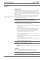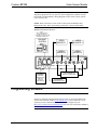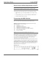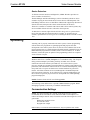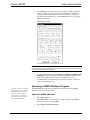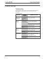
1
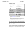
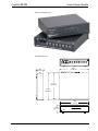
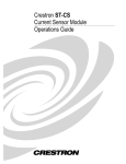
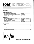
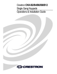
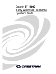
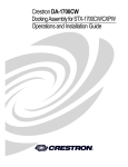
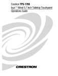
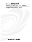
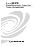
Crestron ST-VS
Video Sensor Module
Operations Guide
This document was prepared and written by the Technical Documentation department at:
Crestron Electronics, Inc.
15 Volvo Drive
Rockleigh, NJ 07647
1-888-CRESTRON
All brand names, product names and trademarks are the property of their respective owners.
© 2003 Crestron Electronics, Inc.
Crestron ST-VS
Video Sensor Module
Contents
Video Sensor Module: ST-VS
1
Introduction ............................................................................................................................... 1
Features and Functions................................................................................................ 1
Specifications .............................................................................................................. 1
Physical Description.................................................................................................... 2
Industry Compliance ................................................................................................... 5
Setup .......................................................................................................................................... 6
Identity Code ............................................................................................................... 6
Hookup ........................................................................................................................ 6
Programming Software.............................................................................................................. 7
Earliest Version Software Requirements for the PC ................................................... 8
Programming with SIMPL Windows.......................................................................... 8
Uploading ................................................................................................................................ 11
Communication Settings ........................................................................................... 11
Uploading a SIMPL Windows Program ................................................................... 13
Problem Solving ...................................................................................................................... 15
Troubleshooting ........................................................................................................ 15
Further Inquiries........................................................................................................ 16
Future Updates .......................................................................................................... 16
Return and Warranty Policies.................................................................................................. 17
Merchandise Returns / Repair Service ...................................................................... 17
CRESTRON Limited Warranty ................................................................................ 17
Operations Guide – DOC. 5767A
Contents • i
Crestron ST-VS
Video Sensor Module
Video Sensor Module: ST-VS
Introduction
Features and Functions
The Crestron® video sensor, ST-VS, is used to detect the presence of a video signal
coming out of the baseband video port (typically the yellow RCA or BNC output
jack on an A/V device) for up to four independent sources (i.e., VCRs or TVs). The
ST-VS detects video with minimum peak-to-peak amplitude of 0.5 VDC (sync to
white level). It can also accept audio signals up to 2 Vrms.
Functional Summary
•
The ST-VS is used to detect the presence of a baseband video signal
•
Senses four independent sources (ie. VCRs, DVDs, etc)
•
Provides power status information to the control system based on the
presence of a video signal from any given device
Specifications
The table below provides a summary of specifications for the ST-VS.
ST-VS Specifications
SPECIFICATION
DETAILS
Power Requirements
3 Watts (.25A @ 24VDC) - Cresnet®
or 0.5A @ 12 VDC external power supply
(PW-1205 supplied with ST-VS, PWI-1210
supplied with STI-VS)
Default Net ID
3C
Specifications continued on next page.
Operations Guide – DOC. 5767A
Video Sensor Module: ST-VS • 1
Video Sensor Module
Crestron ST-VS
ST-VS Specifications (continued)
SPECIFICATION
Control System Update Files
DETAILS
1, 2, 3
2-Series Control System
Version C2-2.000.CUZ or later
CEN/CN-TVAV
Version 5.10.13V.UPZ or later
CNMSX-AV/PRO
Version 5.01.35X.UPZ or later
CNRACKX/-DP
Version 5.01.35W.UPZ or later
ST-CP
Version 4.02.04S.UPZ or later
Ports/Connectors
NET
Two 6-pin, RJ type connectors
VIDEO 1 through 4
Four pair of RCA Type connectors
12 VDC, 0.5A
One – Male receptacle for external power pack
Rack Space
1 unit high, ½ unit wide
Environmental Temperature
Environmental Humidity
Dimensions & Weight
41° to 113°F (5° to 45°C)
10% to 90% RH (non-condensing)
Height: 1.70 in (4.32 cm)
Width:
6.94 in (17.63 cm)
Depth:
6.32 in (16.06 cm)
Weight: 1.92 lb (0.87 kg)
1.
The latest software versions can be obtained from the Downloads | Software Updates section of the
Crestron website (www.crestron.com). Refer to the note that follows.
2.
Crestron 2-Series control systems include the AV2, CP2/CP2E, MP2/MP2E, PAC2, PRO2 and
RACK2.
3.
Filenames for CNX and ST-CP update files have a UPZ extension. Files on the website may be .zip
or self-extracting .exe files containing the .cuz or .upz file. To avoid program problems, make sure
you are using the update file with the correct suffix letter (e.g., S, V, W, X).
NOTE: Crestron software and any files on the website are for Authorized Crestron
dealers and Crestron Authorized Independent Programmers (CAIP) only. New users
may be required to register to obtain access to certain areas of the site (including the
FTP site).
Physical Description
The ST-VS is housed in a black enclosure with labels on the front and rear panels.
On the front of the unit there are six LEDs for indicating the unit’s current status. All
connections are made to the back of the unit. Refer to the physical view shown after
this paragraph. There are four rubber feet on the base of the unit for stability and to
prevent slippage.
2 • Video Sensor Module: ST-VS
Operations Guide – DOC. 5767A
Crestron ST-VS
Video Sensor Module
ST-VS Front and Rear View
ST-VS Physical Views
CRESTRON ELECTRONICS INC. ROCKLEIGH, N.J. 07647
6.94 in
(17.63 cm)
1.50 in
(3.81 cm)
6.13 in
(15.58 cm)
6.32 in
(16.06 cm)
7.07 in
(17.95 cm)
VIDEO SENSOR
1.78 in
(4.52 cm)
PWR NET
CRESTRON
Operations Guide – DOC. 5767A
VIDEO
1
2
3
4
ST-VS
Video Sensor Module: ST-VS • 3
Video Sensor Module
Crestron ST-VS
Ports
A number of ports are provided on the back of the ST-VS. Each has a silk-screened
label. Refer to the illustration and descriptions below.
ST-VS Ports
CRESTRON ELECTRONICS INC. ROCKLEIGH, N.J. 07647
12 VDC .5A
NOTE: If the ST-VS is part of the Cresnet system, use of this port is optional.
This DC power socket connector is used to supply power via an external AC power
pack. Crestron recommends and supplies specific power packs for its network
devices. Available power packs include Crestron part number PW-1205 (120 VAC
USA and Canada) or PWI-1210 (230 VAC International).
AC Power Pack Specifications
CRESTRON POWER PACK
INPUT
OUTPUT
PW-1205
120 VAC 60 Hz
12 VDC 500 mA
PWI-1210
230 VAC 50 Hz
12 VDC 1000 mA
AC Power Pack Polarity
NET
These two 6-pin, RJ-12 modular jacks are used to connect the ST-VS module to a
Cresnet control system. When the module is part of the Cresnet system, power may
be supplied via NET if within system power and cable length limits; the supplied
power pack is optional and need not be attached. Two NET ports are available so
that network units can be daisy-chained together. Review the latest revision of the
Network Modular Cable Requirements (Doc. 5682).
Net Connectors
123456
4 • Video Sensor Module: ST-VS
123456
PIN
SIGNAL
1
+24
2
+24
3
Y
4
Z
5
GND
6
GND
Operations Guide – DOC. 5767A
Crestron ST-VS
Video Sensor Module
NOTE: Most 4-conductor phone cables are wired in a crisscross fashion and are not
compatible with Crestron equipment.
If the power pack is attached when the module is part of a Cresnet system, power is
drawn from the power pack. The module does not draw from the network power, but
the network power remains chained.
VIDEO 1 - 4
There are four sets of independent video pass through connectors. These eight RCA
connectors (two per video signal) connect to the (up to) four independent sources
that require sensing.
Indicators
There are six LED indicators located on the front panel of the ST-VS. Each has a
silk-screened label. Refer to the illustration and descriptions below.
ST-VS Indicators
PWR (Power)
This LED illuminates when 12 volts (from the external power pack) or 24 volts DC
(from the network) is supplied to the ST-VS.
NET
This LED illuminates when communication between Cresnet and the ST-VS is
established. Illumination indicates that the SIMPL Windows program currently
loaded has a network device defined at the same network ID as the ST-VS.
VIDEO 1 - 4
These four LEDs illuminate when a video signal on the respective VIDEO connector
exceeds the minimum requirements (threshold) for signal detection.
Industry Compliance
As of the date of manufacture, the ST-VS has been tested and found to comply with
specifications for CE marking.
NOTE: This device complies with part 15 of the FCC rules. Operation is subject to
the following two conditions: (1) these devices may not cause harmful interference,
and (2) these devices must accept any interference received, including interference
that may cause undesired operation.
Operations Guide – DOC. 5767A
Video Sensor Module: ST-VS • 5
Video Sensor Module
Crestron ST-VS
Setup
Identity Code
All equipment and user interfaces within the network require a unique identity code
(Net ID). These codes are two-digit hexadecimal numbers from 03 to FE. The Net
ID of each unit must match an ID code specified in the SIMPL Windows program.
Refer to “Setting the Net ID in Device Settings” on page 10 for details of the SIMPL
Windows procedure.
Refer to the note on page 11 for a
definition of Viewport.
The Net ID of the ST-VS has been factory set to 3C, The Net IDs of multiple STVSs in the same system must be unique. Net IDs are changed from a personal
computer (PC) via the Crestron Viewport.
NOTE: For detailed information on establishing communication between the PC
and control system, refer to “Communication Settings” on page 11. If
communication cannot be established, refer to the “Troubleshooting
Communications” section in the respective Operations Guide for the control system.
Use the following instructions to set or change the Net ID.
1.
Ensure that the device requiring a Net ID change is the only unit connected
to the control system.
2.
Open the Crestron Viewport.
3.
From the Viewport menu, select Functions | Set Network ID. The software
checks the baud rate and then opens the "Set Network ID" window.
4.
In the "Set Network ID" window, select the device requiring a Net ID
change from the Current Network Devices text window.
5.
Select the new Net ID for the device from the Choose the new network ID
for the selected device (Hex): text box.
6.
Click Set ID to initiate the change. This will display the "ID command has
been sent" window.
7.
In the "Command Complete" window, click OK.
8.
In the Current Network Devices text window, verify the new Net ID code.
9.
In the "Set Network ID" window, click Close.
NOTE: The new Net ID code may also be verified by selecting Diagnostic | Report
Network Devices in the Viewport (alternately, select F4).
10. Repeat this procedure for each additional network device requiring a Net ID
change.
Hookup
Refer to the following hookup diagram. Other than making the power connection
last, complete the connections in any order. RCA cables are not supplied.
CAUTION: Use only Crestron power supplies for Crestron equipment. Failure to do
so could cause equipment damage or void the Crestron warranty.
6 • Video Sensor Module: ST-VS
Operations Guide – DOC. 5767A
Crestron ST-VS
Video Sensor Module
NOTE: When installing network wiring, refer to the latest revision of the wiring
diagram(s) appropriate for your specific system configuration, available from the
Downloads | Product Manuals | Wiring Diagrams section of the Crestron website
(www.crestron.com).
NOTE: Refer to the latest revision of the Crestron Network Modular Cable
Requirements (Doc. 5682) when making connections to the port labeled NET.
Hookup Connections for the ST-VS
NOTE:
USE ST-CNB OR CN-RJ11
(SOLD SEPARATELY)
TO CONNECT ST-VS TO 4-WIRE
NETWORK CONNECTOR.
CRESNET
SYSTEM
VIDEO
SOURCE 1
VIDEO
SOURCE 3
VIDEO
SOURCE 2
VIDEO
SOURCE 4
CRESTRON ELECTRONICS INC. ROCKLEIGH, N.J. 07647
OPTIONAL
EXTERNAL
POWER PACK
(500 mA)
(1000 mA
International)
PASS THROUGH TO
DISPLAY or SWITCHER
DAISY CHAIN
TO ADDITIONAL
NETWORK DEVICES
Programming Software
NOTE: Have a question or comment about Crestron software?
Answers to frequently asked questions (FAQs) can be viewed in the Online Help
section of the Crestron website (www.crestron.com). To post a question or view
questions you have submitted to Crestron’s True Blue Support, log in at
http://www.crestron.com/accounts/login.asp. First-time users will need to establish a
user account.
Operations Guide – DOC. 5767A
Video Sensor Module: ST-VS • 7
Video Sensor Module
Crestron ST-VS
Earliest Version Software Requirements for the PC
NOTE: Crestron recommends that you use the latest software to take advantage of
the most recently released features. The latest software is available from the
Downloads | Software Updates section of the Crestron website (www.crestron.com).
The following are the earliest useable software version requirements for the PC:
• SIMPL Windows, any version. Requires SIMPL+ Cross Compiler version
1.1.
• Crestron Database version 15.0.0 or later. Required by SIMPL Windows.
• Crestron Viewport version 3.35 or later.
Programming with SIMPL Windows
NOTE: The following assumes that the reader has knowledge of SIMPL Windows.
If not, refer to the extensive help information provided with the software.
NOTE: The following are file extensions for programs that include an ST-VS,
developed for specific control system types:
.smw source file
.spz
compiled file for 2-series
.bin
compiled file for CNX generation
.csz
compiled file for CNX generation with SIMPL+
.ush
compiled file for CNX generation with SIMPL+ header file
.usp
source code module for SIMPL+
.umc
user macro for SIMPL
NOTE: In the following description, the PRO2 control system is used.
SIMPL Windows is Crestron’s software for programming Crestron control systems.
It provides a well designed graphical environment with a number of workspaces
(i.e., windows) in which a programmer can select, configure, program, test, and
monitor a Crestron control system. SIMPL Windows offers drag and drop
functionality in a familiar Windows® environment.
This section describes a sample SIMPL Windows program that includes an ST-VS.
Configuration Manager is where programmers “build” a Crestron control system by
selecting hardware from the Device Library. In Configuration manager, drag the
PRO2 from the Control Systems folder of the Device Library and drop it in the upper
pane of the System Views. The PRO2 with its associated communication ports is
displayed in the System Views upper pane.
PRO2 System Views
8 • Video Sensor Module: ST-VS
Operations Guide – DOC. 5767A
Crestron ST-VS
Video Sensor Module
The System Views lower pane displays the PRO2 system tree (refer to the following
graphic). This tree can be expanded to display and configure the communication
ports.
Expanded PRO2 System Tree
C2Net-Device Slot in Configuration Manager
To incorporate an ST-VS into the system, drag the ST-VS from the Cresnet Control
Modules | Cresnet Sensing Modules folder of the Device Library and drop it in
System Views. The PRO2 system tree displays the ST-VS in Slot 9, with a default
Net ID of 3C as shown in the following illustration.
NOTE: The first ST-VS in a system is preset with a Net ID of 3C when its symbol is
dragged into the upper pane of System Views. Additional ST-VS units are assigned
different Net ID numbers as they are added.
Operations Guide – DOC. 5767A
Video Sensor Module: ST-VS • 9
Video Sensor Module
Crestron ST-VS
Setting the Net ID in Device Settings
Double-click the ST-VS icon to open the “Device Settings” window. This window
displays the ST-VS device information. If necessary, select the Net ID tab to change
the Net ID as shown in the following figure.
ST-VS “Device Settings” Window
NOTE: SIMPL Windows automatically changes the Net ID values of a device
added to a program if a duplicate device or a device with the same default Net ID
already exists in the program. Always ensure that the hardware and software settings
of the Net ID match. For Net ID hardware setting details, refer to “Identity Code” on
page 6.
ST-VS Symbol in Programming Manager
Programming Manager is where programmers “program” a Crestron control system
by assigning signals to symbols. The following graphic shows the ST-VS symbol in
the SIMPL Windows’ Programming Manager.
Detail View of the ST-VS in SIMPL Windows Programming Manager
The ST-VS provides four discrete video sensors. The <sense> outputs go high
whenever the presence of a video signal is detected at the corresponding input.
10 • Video Sensor Module: ST-VS
Operations Guide – DOC. 5767A
Crestron ST-VS
Video Sensor Module
Device Extenders
To facilitate network functions and diagnostics, SIMPL Windows provides two
device extenders for the ST-VS.
The Poll Manager and The Poll Manager (2 Series Extended) symbols are device
extenders for plug-in control cards and for Cresnet devices and touchpanels. The
Poll Manager takes the device on and offline without need to physically disconnect it
from the network, and reports the current connection status of the device.
The device extenders are available with X-Series and 2-Series control systems; they
are not available with the ST-CP or CN-Series control systems.
To add a device extender, right-click the ST-VS in Program View, point to Insert
Device Extender and select the desired device extender. To program a device
extender, expand the ST-VS in Program View and drag the device extender to Detail
View.
Uploading
Assuming a PC is properly connected to the entire system, Crestron programming
software allows the programmer to upload programs and projects after their
development to the control system. However, there are times when the files for the
program and projects are compiled and not uploaded. Instead, compiled files may be
distributed from programmers to installers, from Crestron to dealers, etc. In those
instances, one has the option to upload via the programming software or to upload
via the Crestron Viewport.
NOTE: The Crestron Viewport is available as a pull-down command from SIMPL
Windows and VT Pro-e (Tools | Viewport) or as a standalone utility. The Viewport
utility performs multiple system tasks, primarily via an RS-232 or TCP/IP
connection between the control system and a PC. It is used to observe system
processes, upload new operating systems and firmware, change system and network
parameters, and communicate with network device consoles and touchpanels, among
many other tasks. Viewport can function as a terminal emulator for generic file
transfer. All of these functions are accessed through the commands and options
inViewport menus. Therefore, for its effectivness as a support and diagnostic tool,
the Crestron Viewport may be preferred over development tools when uploading
programs and projects.
NOTE: Firmware for the ST-VS is not field upgradable.
The following section defines how to upload a SIMPL Windows program. Before
attempting to upload, it is necessary to establish communications.
Communication Settings
NOTE: For laptops and other PCs without a built-in RS-232 port, Crestron
recommends the use of PCMCIA cards, rather than USB-to-serial adapters. If a
USB-to-serial adapter must be used, Crestron has tested the following devices with
good results:
Belkin (large model) F5U103
I/O Gear GUC232A
Keyspan USA-19QW
Other models, even from the same manufacturer, may not yield the same results.
Operations Guide – DOC. 5767A
Video Sensor Module: ST-VS • 11
Video Sensor Module
Crestron ST-VS
The procedure in this section provides details for RS-232 communication between
the PC and the control system. If TCP/IP communication is preferred, consult the
latest version of the Crestron e-Control Reference Guide (Doc. 6052) or the
respective Operations Guide for the control system. These documents are available
from the Downloads | Product Manuals section of the Crestron website
(www.crestron.com). Refer to the following figure for a typical connection diagram
when uploading files.
NOTE: Use a standard DB9 male to female “straight-through” cable.
Typical Connection Diagram when Uploading
Serial Port
PC
DB9 Cable
Computer Port
NET
24 Y Z G
Control
Processor
ST-CNB Cable
ST-VS
1.
Open the Crestron Viewport.
Either launch the standalone version of Viewport, or start SIMPL
Windows, and from the menu bar, select Tools | Viewport.
2.
Refer to the following illustration. From the Viewport menu, select Setup |
Communications settings (alternatively, press Alt+D) to open the “Port
Settings” window.
Setup | Communications Settings Command
12 • Video Sensor Module: ST-VS
Operations Guide – DOC. 5767A
Crestron ST-VS
Video Sensor Module
3.
Select RS-232 as the connection type. Verify that an available COM port
(COM 1 is shown after this step) is selected, and that all communication
parameters and necessary options from the “Port Settings” window are
selected as shown after this step. Click the OK button to save the settings
and close the window.
“Port Settings” Window
NOTE: The parameters shown in the illustration above are the port settings for a
2-Series control system. Consult the Operations Guide for the control system being
used for the exact parameter selection.
4.
To verify communication, select Diagnostics | Establish Communications
(Find Rack). This should display a window that gives the COM port and
baud rate. If communications cannot be established, refer to the
“Troubleshooting Communications” section in the respective Operations
Guide for the control system.
Uploading a SIMPL Windows Program
A control system source file has
the extension .smw. A compiled
SIMPL Windows file has the
extension .spz for a 2-Series
control system, .bin for CNX
generation, and .csz for CNX
generation with SIMPL+.
Operations Guide – DOC. 5767A
The SIMPL Windows file can be uploaded to the control system using SIMPL
Windows or via the Crestron Viewport.
Upload via SIMPL Windows
1.
Start SIMPL Windows.
2.
Select File | Open to view the “Open” window, navigate to the SIMPL
Window file (.smw), and click Open.
3.
Select Project | Transfer Program.
Video Sensor Module: ST-VS • 13
Video Sensor Module
Crestron ST-VS
Upload via Crestron Viewport
1.
Verify that the procedure for “Communication Settings” that begins on
page 11 has been performed.
2.
As shown after this step, select File Transfer | Send Program
(Alternatively, press Alt+P) from the Viewport menu.
File transfer | Send Program Command
3.
The “Send Program” window appears as shown after this step. Click
Browse, locate the completed file (.spz for PRO2) and click Open. This
displays the program’s header information and enables one or both of the
What to Send check boxes. If the program does not contain any SIMPL+
modules, only the SIMPL Program check box is enabled. If it does contain
SIMPL+ modules, then the SIMPL+ Program(s) check box will also be
enabled. Select one or both check boxes and then click Send Program to
begin the transfer.
NOTE: Refer to the respective Operations Guide for control system details about the
other fields in the “Send Program” window.
“Send Program” Window
4.
14 • Video Sensor Module: ST-VS
To verify that the program has been transferred successfully, select
Diagnostics | Report Program Information. This should display a
window that provides details about the current program loaded into the
control system.
Operations Guide – DOC. 5767A
Crestron ST-VS
Video Sensor Module
Problem Solving
Troubleshooting
The following table provides corrective action for possible trouble situations. If
further assistance is required, please contact a Crestron customer service
representative.
ST-VS Troubleshooting
TROUBLE
POSSIBLE
CAUSE(S)
CORRECTIVE ACTION
Unexpected
response from
control system.
Network devices are From the Viewport, poll the network (F4)
not communicating to verify communication.
to the control
system.
Green PWR LED
does not
illuminate.
ST- VS is not
receiving power.
Confirm that power pack securely
plugged into outlet and that the
connector is properly attached to the STVS.
Verify that proper cables are securely
attached to ST-VS NET connectors (for
Cresnet system only).
Yellow NET LED
does not
Illuminate.
Video 1 – 4 LEDs
do not illuminate
Incorrect power
supply.
Use a Crestron power supply, PW-1205,
PWI-1210, or Cresnet.
Improper Net ID.
Verify that ST-VS Net ID matches the
Net ID in the SIMPL Windows program.
Refer to "Identity Code".
Loose network
connection.
Verify that cables attached to ST-VS
NET connectors are proper and secure.
Video signal is
below minimum.
Video signal must have a minimum
peak-to-peak amplitude of 0.5 VDC
(Sync to White level).
Audio signals up to 2 Vrms.
ST-VS is not
receiving signal.
Operations Guide – DOC. 5767A
Ensure that the RCA cables are securely
attached to the ST-VS and the source.
Video Sensor Module: ST-VS • 15
Video Sensor Module
Crestron ST-VS
Further Inquiries
If after reviewing this Operations Guide, you cannot locate specific information or
have questions, please take advantage of the Crestron award winning customer
service team by calling:
•
In the US and Canada, call the Crestron corporate headquarters at
1-888-CRESTRON [1-888-273-7876].
•
In Europe, call Crestron International at +32-15-50-99-50.
•
In Asia, call Crestron Asia at +852-2341-2016.
•
In Latin America, call Crestron Latin America at
+5255-5093-2160.
•
In Australia and New Zealand, call Crestron Pacific at
+613-9480-2999.
You can also log onto the online help section of the Crestron website
(www.crestron.com) to ask questions about Crestron products. First-time users will
need to establish a user account to fully benefit from all available features.
Future Updates
As Crestron improves functions, adds new features, and extends the capabilities of
the ST-VS, additional information may be made available as manual updates. These
updates are solely electronic and serve as intermediary supplements prior to the
release of a complete technical documentation revision.
Check the Crestron website (www.crestron.com) periodically for manual update
availability and its relevance. Updates are available from the Downloads | Product
Manuals section and are identified as an “Addendum” in the Download column.
16 • Video Sensor Module: ST-VS
Operations Guide – DOC. 5767A
Crestron ST-VS
Video Sensor Module
Return and Warranty Policies
Merchandise Returns / Repair Service
1.
No merchandise may be returned for credit, exchange, or service without prior authorization
from CRESTRON. To obtain warranty service for CRESTRON products, contact the factory
and request an RMA (Return Merchandise Authorization) number. Enclose a note specifying
the nature of the problem, name and phone number of contact person, RMA number, and
return address.
2.
Products may be returned for credit, exchange, or service with a CRESTRON Return
Merchandise Authorization (RMA) number. Authorized returns must be shipped freight
prepaid to CRESTRON, 6 Volvo Drive, Rockleigh, N.J., or its authorized subsidiaries, with
RMA number clearly marked on the outside of all cartons. Shipments arriving freight collect
or without an RMA number shall be subject to refusal. CRESTRON reserves the right in its
sole and absolute discretion to charge a 15% restocking fee, plus shipping costs, on any
products returned with an RMA.
3.
Return freight charges following repair of items under warranty shall be paid by
CRESTRON, shipping by standard ground carrier. In the event repairs are found to be nonwarranty, return freight costs shall be paid by the purchaser.
CRESTRON Limited Warranty
CRESTRON ELECTRONICS, Inc. warrants its products to be free from manufacturing defects in materials and
workmanship under normal use for a period of three (3) years from the date of purchase from CRESTRON,
with the following exceptions: disk drives and any other moving or rotating mechanical parts, pan/tilt heads and
power supplies are covered for a period of one (1) year; touchscreen display and overlay components are
covered for 90 days; batteries and incandescent lamps are not covered.
This warranty extends to products purchased directly from CRESTRON or an authorized CRESTRON dealer.
Purchasers should inquire of the dealer regarding the nature and extent of the dealer's warranty, if any.
CRESTRON shall not be liable to honor the terms of this warranty if the product has been used in any
application other than that for which it was intended, or if it has been subjected to misuse, accidental damage,
modification, or improper installation procedures. Furthermore, this warranty does not cover any product that
has had the serial number altered, defaced, or removed.
This warranty shall be the sole and exclusive remedy to the original purchaser. In no event shall CRESTRON
be liable for incidental or consequential damages of any kind (property or economic damages inclusive) arising
from the sale or use of this equipment. CRESTRON is not liable for any claim made by a third party or made by
the purchaser for a third party.
CRESTRON shall, at its option, repair or replace any product found defective, without charge for parts or
labor. Repaired or replaced equipment and parts supplied under this warranty shall be covered only by the
unexpired portion of the warranty.
Except as expressly set forth in this warranty, CRESTRON makes no other warranties, expressed or implied,
nor authorizes any other party to offer any warranty, including any implied warranties of merchantability or
fitness for a particular purpose. Any implied warranties that may be imposed by law are limited to the terms of
this limited warranty. This warranty statement supercedes all previous warranties.
Trademark Information
All brand names, product names, and trademarks are the sole property of their respective owners. Windows is a registered trademark of
Microsoft Corporation. Windows95/98/Me/XP and WindowsNT/2000 are trademarks of Microsoft Corporation.
Operations Guide – DOC. 5767A
Video Sensor Module: ST-VS • 17
Video Sensor Module
Crestron ST-VS
This page intentionally left blank.
18 • Video Sensor Module: ST-VS
Operations Guide – DOC. 5767A
Crestron ST-VS
Video Sensor Module
This page intentionally left blank.
Operations Guide – DOC. 5767A
Video Sensor Module: ST-VS • 19
Crestron Electronics, Inc.
15 Volvo Drive Rockleigh, NJ 07647
Tel: 888.CRESTRON
Fax: 201.767.7576
www.crestron.com
Operations Guide – DOC. 5767A
12.03
Specifications subject to
change without notice.