1
MultiTRON
19’’ rack system
User Manual
MultiTRON
Disclaimer
This manual by ALLIED DATA TECHNOLOGIES B.V. (hereinafter referred to as ALLIED DATA TECHNOLOGIES)
is a reflection of the current state of the products described in it.
It has been our aim to provide a description, which would be sufficiently complete and clear to see to it that our products
would be as easy as possible to use. However, this manual may contain technical
inaccuracies and typing errors. As a result of rapid developments, we are also obliged to reserve the right to implement
technical modifications and developments without prior notice.
For this reason, ALLIED DATA TECHNOLOGIES does not warrant the contents of the manual and its permanent applicability.
Neither is ALLIED DATA TECHNOLOGIES liable for possible loss of information or any improper use of information resulting
from the consultation of this manual. In particular, ALLIED DATA TECHNOLOGIES is not liable for any direct or indirect damage
(including loss of profits and comparable losses) resulting from the use or improper use of this manual, even if ALLIED DATA
TECHNOLOGIES or a representative of ALLIED DATA TECHNOLOGIES has been informed that such damage could arise.
Of course, this does not detract from out legal liability for intentionally inflicted damage or damage on the basis of gross
negligence.
In relation to the information mentioned in this manual, ALLIED DATA TECHNOLOGIES does not warrant that there are no
industrial rights of ownership (trademarks, patents, etc.). This also applies to commonly used brand names, company names
and product names, but these are subject to the relevant trademark, patent and registered design laws.
The information is not to be copied, translated, reproduced or transferred or stored on any electronic medium or other
machine, neither wholly nor partly, without prior permission in writing from ALLIED DATA TECHNOLOGIES.
The sale and use of software is subject to the ALLIED DATA TECHNOLOGIES General Terms of Delivery and Payment as
well as its License Terms. Should any term regarding the disclaimer be or become void for legal reasons, this will not affect
the other terms.
Allied Data Technolgies bv
P.O.Box 788
NL-3200 AS SPIJKENISSE
The Netherlands
© 2003
Allied Data Technologies, CopperJet, Tornado, Trident, Tron, ADSL, Acecat, First and Teltron
are registered trademarks of ALLIED DATA TECHNOLOGIES B.V.
IBM is a registered trademark of International Business Machines Corp (IBM).
MNP is a registered trademark of Microcom Inc.
2
MultiTRON
3
MultiTRON
CONTENTS
1.
INTRODUCTION.......................................................................................... 6
2.
INSTALLING THE MMU................................................................................. 9
2.1
2.2
2.3
2.4
3.
COMMUNICATION WITH THE RACK..............................................................11
3.1
3.2
3.3
3.4
3.5
3.6
4.
T ERMINATING THE CONNECTION.................................................................. 11
MAIN MENU........................................................................................... 13
RACK MENU .......................................................................................... 14
MODEM MENU ........................................................................................ 16
GROUP MENU ......................................................................................... 19
MANAGER MENU ..................................................................................... 20
AUTO DIALBACK .......................................................................................21
4.1
4.2
4.3
4.4
5.
INSTALLING MODEMS .................................................................................9
COUPLING RACKS .....................................................................................9
CONNECTING A PC OR TERMINAL ................................................................. 10
CONNECTING A MODEM............................................................................. 10
DIALLING IN.......................................................................................... 22
PROGRAMMING THE TEXTS ......................................................................... 23
DIALLING OUT ....................................................................................... 24
AUTO DIALBACK MENU OPTION.................................................................... 25
MMU COMMANDS ......................................................................................26
5.1
5.2
5.3
5.4
5.5
5.6
COMMAND STRUCTURE ............................................................................. 27
DATABASE............................................................................................ 28
TYPE COMMAND .................................................................................... 29
GET COMMAND ...................................................................................... 30
SET COMMAND ...................................................................................... 30
ERROR MESSAGES .................................................................................. 31
6.
SNMP.......................................................................................................32
7.
LOGFILE ..................................................................................................33
7.1
7.2
7.3
8.
LOGFILE FORMAT .................................................................................... 34
T IME REGISTRATION................................................................................ 35
LOGFILE DEFINITIONS .............................................................................. 37
SOFTWARE UPGRADE .............................................................................39
8.1
8.2
8.3
8.4
UPLOADING MODEM SOFTWARE (LOCAL). ....................................................... 39
UPLOADING MODEM SOFT WARE (REMOTE)...................................................... 40
UPLOADING MMU SOFTWARE (LOCAL)........................................................... 40
UPLOADING MMU SOFTWARE (REMOTE)......................................................... 41
4
MultiTRON
APPENDIX 1: MMU COMMANDS ........................................................................ 43
APPENDIX 2: ERROR MESSAGES ....................................................................... 44
APPENDIX 3: USER AND DATACLASSES............................................................. 45
APPENDIX 4: MMU DATA STRUCTURE. ............................................................... 46
APPENDIX 5: TECHNIC AL SPECIFICATIONS. ...................................................... 49
5
INTRODUCTION
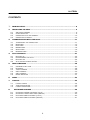
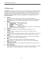
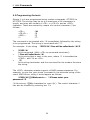
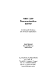
1. INTRODUCTION
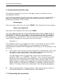
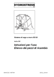
Growing interest in data communication in recent years has resulted in
an increasing demand for the required hardware. Consequently, the use
of multiple modem systems within companies is also escalating. To
facilitate the management of these modems in a simple and efficient
manner TRON supply a Modem Management System suitable for 19”
Modem Racks.
19” Modem Rack
Backplane
V
o
e
d
i
n
g
M
o
d
e
m
M
o
d
e
m
M
o
d
e
m
M
o
d
e
m
M
o
d
e
m
M
o
d
e
m
M
o
d
e
m
M
o
d
e
m
M
o
d
e
m
M
o
d
e
m
M
o
d
e
m
M
o
d
e
m
M
o
d
e
m
M
o
d
e
m
M
o
d
e
m
M
o
d
e
m
1
2
3
4
5
6
7
8
9
10
11
12
13
14
15
16
M
M
U
Terminal
Each 19” Modem Rack can accommodate 16 special card modems. To
permit central management of these modems the rack can be equipped
with a Management Module (or MMU). This module and the modems are
powered by a central, double power supply.
6
prev
rack
next
rack
INTRODUCTION
The Modem Management Unit fulfils the following functions:
• Configuration
The configuration of the modems is set in the MMU. The modems are
configured automatically when they are inserted into the rack. A total
of 10 different configurations can be defined.
• Control
Overview of the current status of the modems. Transmission of SNMP
traps to a management station.
• Security
A ‘Call-back security’ option is available. See ‘Auto dialback’ chapter.
• Logging
All connections made via the modems are logged, together with all
instances of the system being turned on and off and the installation
or removal of modems.
• Rack coupling
Racks can be coupled via the MMU. This permits a maximum of 15
MMU’s to be controlled from a single connection.
• Operation
The MMU can be coupled to a terminal or a PC via an RS232
connection, and also via a modem connection. The system can be
operated from the PC using a standard terminal program.
• Test functions (asynchronous only):
The RS232 port on the PC can be switched through to a specific
modem in order to give this modem direct commands or to make a
connection.
7
Installing the MMU
2. Installing the MMU
The modem management unit is installed in the right-hand side of the
rack. Units bearing production code MM3994 or higher may be installed
in the rack whilst the rack power supply remains on. The red error LED
on the management unit will then burn briefly. During start -up the
yellow (busy) LED will burn, and once the MMU is ready only the green
(OK) LED will continue burning.
2.1 Installing modems
A modem can be installed in the rack whilst the power supply is
switched on.
If the management unit is present the power to the modem will only be
switched on after it has been in the rack for approximately one second.
2.2 Coupling racks
It is also possible to stack multiple racks above one another in a 19”
unit. This enables multiple racks to be addressed via one connection. A
standard male-to-female cable is used to couple the racks, one of which
is supplied with each rack. The lowest D9 connector on a rack has to be
connected with the uppermost D9 connector on the rack below it. On
installation the racks are then automatically numbered from the top (1)
to the bottom (n). The rack number appears on the 7-segment display of
the management unit and is also stored in the management unit itself.
From rack number 10 the display is numbered using a letter (A for 10
etc.). Rack numbering increments automatically, but does not decrement
back. This means that if a unit is removed from the chain, all the others
units will retain their own number. If the management unit that was
removed is replaced, it must therefore be replaced in the same position
in the chain.
9
Installing the MMU
2.3 Connecting a PC or terminal
A PC or terminal can be connected to the D9 connector on the front of
the management unit. The PC or terminal must be configured to 19200
BPS, 8 databits, 1 stopbit. The PC can also be connected to the
uppermost D9 connector on the rear of the management unit. In that
case the PC has be configured to 115200 BPS. If multiple racks are
coupled the PC must be connected to the uppermost rack. The
connection is made with a cable as described in 0.
2.4 Connecting a modem
The management unit can also be operated via a modem. The modem
must then be connect to the lowest D9 connector on the rear of the
management unit. If multiple racks are connected the modem must be
connected to the lowest rack. After being connected to this connector, or
when switching it on when connected, the modem will be automatically
configured to DTE: 115K2, E0, S0=1. The connection is made with a
cable as described in 2.2
10
Communication with the rack
3. Communication with the rack
This chapter describes how you as 'manager' make a connection to the
management system.
Once a communication program has been started up on the connected PC, or
when the connected modem becomes connected to another modem, the
following will appear on the screen:
Please login:
Enter your user name (for new units: TRON). The following will then appear:
Enter your password:
Now enter your password (for new units: MMU).
You may make a maximum of three attempts before being logged off by a
hardware DTR/DSR dip, see chapter 0. The password can also be changed,
see chapter 0. Once a correct login has been performed the yellow LED on
the management unit will burn. You will now see a screen displaying the
‘main menu’. Displayed in the main menu you will see:
Selection: 1
This indicates that you are logged into rack 1. If a number of menu options
separated by dots is displayed then you are located in a submenu.
Communication between the Management Module and a PC is possible in two
manners:
1.
Menu Mode. The user can view and change the configuration of the rack
by means of menu selections. The software also permits switching
through to other racks (if other racks are coupled)
You can always return to a previous menu from the submenus by
pressing <ESC> or 0 <ENTER>. Using the + and - keys you can move
directly to the following/previous submenu, or move to the following
page when the current menu is a table. When entering data (e.g. a
group number or string) the change can be undone by pressing <ESC>.
When nothing is entered and <ENTER> is pressed, a default value is
filled in. The menu structure is described in the following paragraphs.
2.
MMU Command Mode. Communication is then performed by means of
commands based on the SNMP protocol. See chapter 0.
3.1 Terminating the connection.
11
Communication with the rack
A connection can be terminated from the main menu by selecting:
9.
logout
When logged into the MMU via a modem connected to the male connector on
the rear panel of the MMU (DTE connection), the DTR will give a dip of
approximately 1 second immediately on logging off. As a result of this the
modem will terminate the connection. When logged in via one of the other
two connectors (DCE connections), the same applies on the port concerned
for DSR and DCD (these signals are coupled in the two DCE connections).
The connection can also be terminated by the hardware. When logged into
the MMU via a modem connected to the DTE connection, the DCD must be
made inactive (a normally configured modem does this itself once the
telephone connection is terminated). A logout is then also performed at the
same time, which in turn results in a DTR dip. When logged in via one of the
other two connectors (DCE connectors) the port concerned must also be
made inactive. This of course also results in a logout, which once again
results in a DSR (+DCD) dip.
12
Communication with the rack
3.2 Main menu
The following options are available in the main menu:
1.
2.
3.
4.
5.
6.
7.
8.
9.
Rack
This option selects the submenu for rack specific matters. See
paragraph 0
Modem
This options permits the 16 modems to be addressed individually, to
establish which group they belong to for example. See further
paragraph 0
Group
This option permits mass configuration for a group of modems. A
maximum of 10 different groups can be defined. See paragraph 0
Management
This option permits manager names and passwords to be defined or
changed for a maximum of 20 managers. A class can also be set for each
manager, see paragraph 0. In coupled racks you should also ensure that
the management list in each rack is identical.
Auto dialback
This option provides you with access to the list of ADB users. See
chapter 0.
Logfile
This choice provides you with access to the logfile. See chapter 0.
Previous rack
This enables you to login to the previous rack that is coupled to the
male D-9 connector on the rear panel of the MMU. Without you noticing
anything further, the current rack will log you in to the previous rack
using your own name / password combination. If this name / password
combination is not known on the rack selected, the default name /
password combination will be used. It is also possible that another
manager may already be logged in to this rack. In that case it will not
be possible to switch through to this rack.
Next rack
The same as Previous rack, but now the following rack via the female
D-9 connector on the rear panel of the MMU.
Logout
The ‘logout' command is used to terminate a session. You will also be
logged out if the terminal DTR signal or the modem carrier detect
signal is dropped.
13
Communication with the rack
3.3 Rack menu
This submenu offers the following options:
1.
2.
3.
4.
Rack number
This field indicates the rack number and cannot be modified.
Advanced
This calls up a submenu :
1.
manager index. Indicates the number of the manager logged in.
2.
system clock. Indicates the time elapsed since the MMU was
started (in seconds).
3.
last log entry. Indicates which entry in the log was written last.
4.
screen refresh time. By setting this to a value greater than 0
the modem menu is refreshed if the status of one of the modems
changes. The value entered is the minimum number of seconds
between two refreshes (e.g. 5 seconds).
5.
renumber racks. This function can be activated if the rack
numbering is no longer correct (e.g. after changing a management
system).
6.
reset eerom strings. This function erases all data from the ADB
list.
7.
clear logfile. Only used by the manufacturer.
8.
debug info.
1.
send traps. Switch on/off sending QSNMP Traps to the
SNMP Proxy agent of the MMU.
2.
last trap number. Sequence number of the last trap
sent.
3.
upload new MMU software. See Chapter 0.
4.
upload new modem software. See Chapter 0.
5.
debug info on/off. Only used by the manufacturer.
6.
debug info modem. Only used by the manufacturer.
7.
task list. Only used by the manufacturer.
8.
watchdog timers. Only used by the manufacturer.
9.
test function. Only used by the manufacturer.
9.
rack f.busy.
1.
rack f.busy off. Switch off “forced busy” at all modem
slots.
2.
rack f.busy on. Switch on “forced busy” at all modem
slots.
3.
rack f.busy control off. Disable the use of the “forced
busy” of all modem slots. This function is only used by
the manufacturer.
4.
rack f.busy control on. Enable the use of the “forced
busy” of all modem slots. This is default behaviour.
Software version
This field indicates which software version is contained in the MMU.
Organisation name
14
Communication with the rack
5.
6.
7.
8.
9.
The text entered into this field appears automatically above every
menu screen.
Manager name.
This field is only used to record information and can be filled in as
required. It has no effect on modem functions or MMU functions.
Telephone (work).
This field is only used to record information and can be filled in as
required. It has no effect on modem functions or MMU functions.
Telephone (home).
This field is only used to record information and can be filled in as
required. It has no effect on modem functions or MMU functions.
Serial number
This is the PCB serial number and can only be filled in by the
manufacturer.
15
Communication with the rack
3.4 Modem menu
If modem is selected in the main menu, an overview of the modems present
and their status is displayed. Each modem can be addressed individually by
entering the number of the required modem (1.. 16). This number is not
coupled to an individual modem, but to the position occupied by the modem
in the rack. Once a modem has been selected you can choose from the
following options:
1.
2.
3.
4.
5.
6.
7.
8.
Group:
Here you can set the group to which the modem belongs, see
paragraph 3.5. If you change this setting the modem will immediately
be configured with the init strings belonging to the group selected.
State:
This indicates which state the modem is in:
1.
Not installed
No modem present.
2.
Available Modem present.
3.
Online
Modem online.
4.
Reserved This modem is reserved to call back a user during the
elapse of time of the ADB delay.
Power:
This can be used to turn the modem power supply on or off.
F.Busy:
If this is option is switched on, the line for this modem will be
disabled. The
modem can then no longer be used normally. ‘Forced Busy’ can be used
to disable a line if a fault is occurring in the modem or on the line.
Mode:
If a modem has a data connection the data communication standard
(e.g. V32bis, V34) will be displayed here.
BPS:
If a modem has a data connection the speed at which data
communication is taking place (e.g. 9600, 24000) will be displayed
here.
Disconnect reason:
If the data connection is terminated the disconnection reason will be
displayed here.
Error correction:
If a modem has a data connection the type of error correction and data
compression will be displayed here (e.g. None, MNP5, V42bis).
16
Communication with the rack
9.
10.
11.
12.
13.
14.
15.
Quality:
This option displays the quality of the modem connection (if
established):
1.
0..8
good
2.
9..16
reasonable
3.
16..63
poor
Signals:
Status of the modem handshake signals.
0.
dsr
1.
cts
2.
dcd
3.
dtr
4.
rts
5.
undef
6.
undef
7.
carrier detected
Bits 0 to 4 are active low. These signals are refreshed every few
seconds.
Reset:
The modem will be reset (by turning the power supply off and back on).
FactoryReset:
The modem is reset and receives the 'Factory settings'. This has the
same effect as turning on the modem with the ‘Softkey’ held in.
Initialise:
The modem first receives a 'Factory reset' and then the init strings
defined in the group are sent to the modem.
Analyse serial data:
This submenu provides a choice between TXD or RXD data.
1.
TXD: The data entering the modem via the RS232 port and also
sent to the PC or terminal.
2.
RXD: The data sent by the modem via the RS232 port and also to
the PC or terminal.
The Analyse function can be terminated by pressing <ESC>.
DirectConnect:
The PC or terminal is now connected to the modem. This will enable
you to examine and change the modem settings and enter random
commands. It is also possible to make a connection using the modem.
The function can be terminated by typing ‘%%%’.
17
Communication with the rack
The AnalyseTxd, AnalyseRxd and DirectConnect commands use the speed to
the modem that has been set in the group. This may be different to the
speed to the PC or terminal. Flowcontrol between the modem and MMU for
these functions has not yet been implemented.
The MMU can only communicate with one modem at a time. When using the
AnalyseTxd, AnalyseRxd en DirectConnect functions all modem
monitoring/operating functions will be temporarily disabled. For example: If
you were configuring modem 3 with the DirectConnect function and a modem
was changed at position 7, the MMU would not detect that change. Modem 7
would then not be configured automatically.
18
Communication with the rack
3.5 Group menu
In this menu the following options can be set for each group:
1.
Speed:
DTE speed of these modems, 300..115200 BPS. This speed is used
when transmitting the init strings and for the AnalyseTxd, AnalyseRxd
and DirectConnect functions in the modem menu. Default: 19200.
2.
Auto Config:
If this is on (default), a modem will be configured automatically with
the init strings when inserted into the rack if the power supply is
switched on and the MMU is present. If the rack power supply is
switched on the modems will not be initialised. In that case the
modems will retain the settings of the previous configuration. A
condition for this is that the last init string ends with the &W command
(store the configuration in the modem itself).
[3..12]
. Initstring A..J:
These strings contain the AT command strings sent to the modems
from the group. See 'Auto Config' and 'Initialise'.
13. Auto line busy:
If this option is on, the line for each modem in the group will be
disabled if the modem is absent or if the power supply for that modem
fails. Default is on.
14. ADB Delay:
Time between dialling in and dialling out in, seconds. This value should
never be less than 20 seconds. Default 45 Sec.
15. Initialise:
Function that sends the init strings to all modems in this group.
16. Upload new software:
This initiates the upload of new modem software. After selecting this
option the MMU expects an ASCII upload of a software file in Motorola
hex format, with which all the modems in the group will then be
programmed. Ensure that the file to be sent is the correct one, as an
erroneous upload cannot be reversed.
If the group is being used as a dial-out group for auto dial back, then the
setting for this group should basically be the same in every rack.
See the chapter concerning auto dial back.
19
Communication with the rack
3.6 Manager menu
The manager menu is a list of persons authorised to login to the MMU.
Everyone logging in as a manager has a specific user-class. The following
user-classes are available:
1.
2.
3.
4.
Supervisor:
The supervisor can do everything the manager can, the supervisor can
also enter new managers and modify manager data.
Manager:
In principle the manager can do everything described in this user
manual. A manager is however unable to modify data in the auto
dialback list and the manager table.
ADB Editor:
The ADB editor can only modify the auto dialback list. The ADB editor
can therefore enter new users, but has no access to modem and group
menus
Technician:
The technician can modify the modem and group menus, but only read
(not modify) the auto dialback list.
Data that is not visible to a manager is referred to as being ‘protected’.
Passwords are always protected and can therefore never be viewed. The data
in the ‘rack’ submenu can be viewed by everyone, but only entered by a
manager and supervisor.
20
5. MMU Commands
4. Auto dialback
The auto dialback system serves as a security measure for a public dialin point. It is based on calling back system users using a telephone
number retrieved from a system user list. If a hacker possesses a valid
name/password, access to the system will still be denied, because the
system will attempt to call back on the telephone number of the genuine
user. The auto dialback system functions as follows:
•
A user dials in on one of the modems in the dial-in group. The user
is requested to enter his name and password.
•
The name and password entered are searched for in the auto
dialback list and may be in either upper or lower case. If racks are
coupled, a search is made through all the racks present. If the
search is successful the system reads the telephone number and
the number of the dial-out group from the auto dialback list.
•
The system then determines whether a modem in the selected dial
out group is available. If that is the case the user is called back
via that modem following the elapse of the time set in the group
menu of the dial-out modem. This time must be at least 20
seconds. The dial-out modem may be located in a different rack to
the dial-in modem.
It should be noted that the auto dialback function and the identification
of a user are in no way related to logging in and being identified as
‘manager’.
The number of users in the auto dialback list is dependent on the
number of racks coupled. A single rack may contain a maximum of 2000
users, provided the average length of the user name is no longer than
24 characters. If coupled racks are used, the number of possible users
increases in proportion to the number of racks.
21
5. MMU Commands
4.1 Dialling in
To use a modem as a dial-in modem this should in principle be set in
the modem. This is set by including the following in the initialisation
string (Initstring A):
S80=129 Z
The S80 setting only becomes active following a modem rest. The Z
command is used for this purpose. The dial-in option is turned off with:
S80=1 Z
Of course the modem must also be set to auto answer: S0=1.
If nothing is connected to the RS232 port on the dial-in modem, DTR
should be disabled with &D0. The text that the modem sends to the
user has to be programmed into the modem, for example:
string
string
string
string
string
string
1:
2:
3:
4:
5:
6:
Welcome to ..... , enter your name:
Enter your password:
Identification correct, you will be called back.
Identification incorrect.
Maximum identification time elapsed.
The system is busy.
If the modem is set up as a dial-in modem, once the user has entered a
username and password an interrupt is sent is to the management
system. The management system then takes the name/password
combination from the modem and uses it as the reference for the search
in the auto dialback list (or in multiple racks: lists).
Following that, one of the following strings will be sent back:
•
•
•
•
•
If the user cannot be found, string 4 is sent.
If the user is found and a modem in the dial-out group is
available, string 3 is sent.
If no modem is available, string 6 is sent.
If the user fails to enter a name or password within the allocated
time, string 5 is sent.
If the management system is not present, or for any other reason
fails to send a message back to the modem within a specific time,
a ‘SYSTEM TIMEOUT’ is sent.
22
5. MMU Commands
4.2 Programming the texts
Strings 1 to 6 are programmed using modem commands AT*P250 to
AT*P255. The strings may be up to a maximum of 64 characters in
length, and may also contain a <CR>, a <CR-LF> and an <ESC>
character. These are entered by means of a control character (^)as
follows:.
<CR> :
<CR-LF> :
<ESC> :
^:
^M
^J
^[
^^
The command is terminated with ^M immediately followed by the string
to be programmed. The string is terminated with ^Z.
For example: In the string
•
•
•
*P253^M^JYou will be called back.^M^Z
*P253^M
Is the command. (With <CR> as command terminator)
^JYou will called back.^M
Is the string that is sent to the user, where ^J is translated as
<CRLF> and ^M as <CR>.
^Z
Is the string terminator and the command for the modem the store
the string.
The <ESC> character enables support of ANSI escape sequences. For
example, to give the ‘goto home’ command in the welcome string of the
user’s ANSI driver, string 1 would appear as follows:
*P250^M^[[HWelcome to … ^JPlease enter your
password:^Z
(In this string ^[[H is translated to <esc>[H ). The control character ^
can also be inserted by entering two ^’s.
23
5. MMU Commands
The commands can also be placed in the group menu of the modem
management system, so that the strings are programmed into the
modems automatically on initialisation, or when being plugged in. An
example of the groups settings for an auto dialback group is provided
below:
Initstring A :
Initstring B :
name: ^Z
Initstring C :
Initstring D :
Initstring E :
Initstring F :
Initstring G :
Initstring J :
S80=129 Z
*P250^M^JWelcome to .... , please enter your
*P251^M^JEnter your password: ^Z
*P252^M^JYou will be called back.^M^Z
*P253^M^JIdentification incorrect.^M^Z
*P254^M^JIdentification time elapsed.^M^Z
*P255^M^JSystem busy, try again.^M^Z
S0=1 &D0 &W
After setting these strings in the menu for the correct group(s) the
initialisation command can be given in these group(s) (menu option 15),
so that the strings are sent to the modem.
If you make use of multiple dial-in modems that are available via
different telephone numbers, it is possible to program different strings
into each modems, enabling a text to be displayed to the user in a
language that is dependent on the telephone number used.
4.3 Dialling out
Multiple dial-out groups can also be defined, so that each user,
depending on their identification, can be connected to a specific system.
The initialisation string for the dial-out modems for a specific group can
be set in the ‘group’ menu..
When using auto dialback in coupled racks the group setting for the dialout group in each rack should be the same, as it is not possible to
predict from which rack the user will be called back. If you require a
specific dial-out group to consist only of modems in a specific rack, you
should ensure that that there no modems present in other racks with
that group number. No modems that can be used to dial in may belong
to the dial-out group, as that would result in a conflict if the
management system ever wanted to dial out on a modem receiving an
incoming call at the same time.
24
5. MMU Commands
4.4 Auto dialback menu option
If you select auto dialback in the main menu, the beginning of the user
list will be displayed. Using the <Enter> key you can scroll through the
list continuously. If the user number is known the number can be typed
in followed by <Enter> to display the data for that user:
1.
2.
3.
4.
5.
Name:
Name of the user, max. 64 characters. It is assumed that average
length is somewhat shorter.
Password:
The user’s password. This is not displayed, but can however be
entered or changed if the manager has the authority to do so.
Area code:
This is the dialling code used for calling back the user. This
number may be preceded by an international dialling code plus
country code, and may also contain a comma for a fixed pause or a
“w” for waiting for a dialling tone. Maximum length is 12
characters.
Telephone:
This is the subscriber number for calling back the user. The
maximum length of this number is 9 digits, and it may begin with
zero.
Group:
The dial-out group of the modem to be used to call back this user.
25
5. MMU Commands
5. MMU Commands
The abbreviation SNMP stands for Simple Network Management Protocol,
a component of the Internet standard Network Management Framework.
This protocol formed the basis for the design of several simple
commands that enable the Management Module to exchange data with
the PC. As these commands do not correspond exactly to the SNMP
protocol we refer here to MMU commands.
The same data can be managed in the MMU Command Mode as in the
Menu Mode.
There are three MMU commands:
•
•
•
Type
This is used to request the data structure.
Get
This is used to request the content of a data element.
Set
This is used to modify the content of a data element.
The MMU commands and responses are transmitted over the serial
connection between the PC and the Management Module as strings (the
commands are not echoed). With the aid of these commands a PC
application can manage, and upload and download the data in the racks.
Each command that is transmitted receives a response. To increase
communication speed the MMU can receive multiple commands in a
single burst. It is not necessary to wait for the responses before a new
command is transmitted. The only exceptions to this are the ‘previous
rack’, ‘next rack’ and ‘logout’ commands.
A ‘{’ character (ASCII 123) is used to switch the module from the Menu
Mode into the MMU Command Mode. This character must usually be
preceded by a <CR> to terminate an unfinished menu command.
Switching back to the Menu Mode is achieved by transmitting a ‘}‘
character (ASCII 125) en <CR>, also usually preceded by a <CR>.
26
5. MMU Commands
5.1 Command structure
The command and response strings are divided into several data fields
and are terminated with a <CR>. Examples of the content of some of
these data fields are provided below:
•
•
•
Number:
Each string sent begins with a field of two numbers in which a
Message number is placed. The accompanying responses contain a
copy of this field. This enables a PC to determine which response
corresponds to which command.
Command:
The third character of a command string is the Command letter.
This letter determines the command type; ‘T’ for the Type
command, ‘G’ for the Get command and ‘S’ for the Set command.
Path:
The path points to the element in the structure or in the data on
which the command is to be executed. This path consists of Index
numbers separated by dots. These represent the choices that have
to be made in within the records and/or arrays in order to arrive at
the element. The number is the number of the rack containing the
element. If this is not the same as the current rack number it will
be necessary to first switch to the correct rack (the functions ‘To
Previous Rack’ and ‘To Next Rack’ have been included in the
structure for this purpose).
For example, to view the ‘forced busy’ status of modem 3 in rack 1 the
following path is used: 1.2.3.4
(See appendix for a detailed overview of MMU command structure and
data structure.)
27
5. MMU Commands
5.2 Database
The structure of the data in the Database is built up from several basic
structure types that couples the data together:
A: Array
R: Record.
The data can be of the following types:
C:
I:
L:
E:
D:
H:
P:
•
•
•
•
•
•
Character String
Integer
(0 - 65535)
Long Integer
(0 - 429496296)
Enumerated
(0 - 65535)
Function
Log File
(compressed to Integer)
Password
(coded to Integer)
Record:
A record also contains a list of values. Each value has a name. The
values that a record contains are described in the structure; these
can be called up using the TYPE command.
Array:
An array contains a series of values or records. Each value has its
own serial number. The number of values is contained in the
structure and can be called up using the TYPE command.
Enumerated:
A variable of the enumerated type is an Index number. This index
selects one string from the string list contained in the structure
which belongs to the enumerated type. This string can be called up
using the TYPE command.
Function:
A variable of the function type contains no relevant value. By
addressing this variable however, the corresponding function is
called up. This could be the resetting of a modem for example.
Log File:
The events logged in MMU are compressed into an integer,
following which they are stored in data elements of the Log File
type.
Password:
Passwords are coded into an inter using a special algorithm. This
integer is then stored in a Password variable.
28
5. MMU Commands
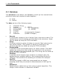
5.3 TYPE command
The type can be called up for all elements in the structure. The
command string consists of a Message Number, a ‘T’ and the path to the
element. The response contains a copy of the Message number followed
by a letter that indicates the Type of the element.
•
Record:
Multiple responses can follow the command for the type ‘Record‘.
Each response contains one string from a string table.
Furthermore, the responses also contain a Dataclass letter. There
are separate read and write authorities associated to each
Dataclass (see appendix for an overview of Dataclasses). An
asterisk (‘*’) indicates that another response is following, so only
the last response does not contain an asterisk. For example:
command: 03T1.1
response: 03*RKrack number
03*RArenumber racks
03*RAreset eerom strings
03*RJsoftware version
03*RAorganisation name
03*RAmanager name
03*RAtelephone (work)
03RAtelephone (home) ( the record fields of rack )
•
Array:
If the element is of the ‘Array’ type then a number follows in the
string that indicates the length of this array. For example:
command: 01T1.2
response: 01A16
(The modem array contains 16
elements)
•
Enumerated:
In the ‘Enumerated‘ type multiple responses can also follow the
command. Each response again contains one string from a string
table, but now indicates a value instead of a submenu. An asterisk
is also used to indicate that another response follows. For
example:
command: 02T1.2.3.3
response: 02*Eoff
02Eon
( the enumerated strings for
Power )
29
5. MMU Commands
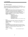
5.4
GET command
The Get command can be applied to all types with exception to Records,
Arrays and Functions.
The command string consists of a Message number, the letter ‘G’ and a
path to the data element.
The response again contains the Message number, the Type and the
content of the data element. The latter value may be an integer, long
integer or string. For Log File and Password types this value is coded
and cannot be used under normal circumstances.
For Enumerated types this is the Index to the currently selected field.
The accompanying string is stored in the structure.
Example:
command:
response:
command:
response:
command:
response:
5.5
04G1.1.5
04CTron
05G1.2.3.3
05E1
06G1.6.3000.1
06H65535
( organisation name = ‘Tron’ )
( from modem 3: power = ‘on’ )
( logfile entry 3000 = 65535 )
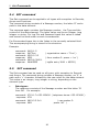
SET command
The Set command can be used on all types, with exception to Records
and Arrays. The command string contains a Message number, an ‘S’, a
path and a ‘=‘ character followed by the new value for the data element.
This value is an integer, long integer or string, depending on the
element type.
•
Data types:
The response consists of the Message number and the letter ‘O’
from OK. For example:
command: 07S1.1.7=053-123456 ( telephone home: 053-123456 )
response: 07O
command: 08S1.2.3.3=0
response: 08O
( van modem 3:
power ‘off ’ )
30
5. MMU Commands
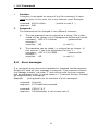
•
Function:
A function is activated by means of the Set command. A value
must be given in this case, but is not however used. Example:
command: 09S1.8=Hello
response: 09O
I.
5.6
( switch to rack 2 )
Password:
The Password can be changed in two different manners:
A.
The new password can be entered as a string; This is then
coded into an integer in the Management Module and stored.
command: 10S2.4.3.2=Secret
( password for
manager 3
response: 10O
in rack 2 )
B.
The password can be coded, i.e. entered as an integer. In
this case an ‘i’ has to be substituted for the ‘=‘.
command: 11S2.4.3.2i=53956
( password for
manager 3
response: 11O
in rack 2 )
Error messages
If a command string cannot be translated or executed the Management
Module will send an error message in response. This response contains
the Message number, the letter ‘F’ and a string with the error number
and an explanatory text. In some cases a ‘=‘ character follows, followed
by supplementary information.
Example:
(see appendix for an overview of error messages)
command: 12invalid
response: 12F7undefined command
command: 13S9.8.7.6.5
response: 13Fracknumber is not current rack=2
31
8. Software upgrade
6.
SNMP
The MMU also possesses an option for sending traps. Traps serve to
report serious errors immediately. The traps are sent to the SNMP trap
driver by means of a foreign protocol, that subsequently transmits them
to a management station using SNMP (such as HP-Openview or NetView
for example).
This SNMP trap driver has been specially written for this application. The
traps that can be sent by the MMU are:
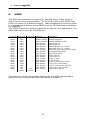
1st word
9nrXX
9nrXX
9nrXX
E0XX
E0XX
E0XX
E0XX
E0XX
E0XX
E0XX
E0XX
E0XX
E0XX
E0XX
E0XX
E0XX
E0XX
E0XX
E3XX
2nd word
0000
0001
0002
0000
0001
0002
0003
0004
0005
0006
0008
0009
000A
000B
000C
000D
000E
000F
old
rackno.
3rd word
new
rackno.
Category
Modem specific
Modem specific
Modem specific
Rack specific
Rack specific
Rack specific
Rack specific
Rack specific
Rack specific
Rack specific
Rack specific
Rack specific
Rack specific
Rack specific
Rack specific
Rack specific
Rack specific
Rack specific
Rack specific
Description
Modem out of rack.
Modem plugged in.
Modem watchdog reset.
Rack power on.
MMU plugged in
Watchdog fired, int 0 failed
Watchdog fired, int 1 failed
Watchdog fired, base context failed
Unimplemented opcode
Rack power down
Power failure 1
Power failure 2
Power 1 back
Power 2 back
Link to previous rack broken
Link to next rack broken
Link to previous rack restored
Link to next rack restored
Racknumber change
The manner in which these traps are sent by the MMU corresponds in
general to the command structure described in chapter 0.
32
8. Software upgrade
7. Logfile
The management module stores many events in memory, together with
the time at which those events occurred. As a result the following data
is stored:
•
•
•
Connection:
Information about each connection made by each modem. For each
connection the following information is stored: start time,
duration, mode (V standard), speed, error correction type and
compression, quality and reason for disconnection. In case of auto
dialback the user number is also stored.
Not installed:
Start time and duration of a modem’s removal/absence from the
rack.
Power:
Rack switching on and switching off time. Any failure of either
power supply is also recorded.
This data is recorded as micro events and can only be viewed in
compressed form using the menu option 'logfile'. This compression
format is described further in the appendix.
When the logfile becomes full the oldest data present is overwritten.
The logfile is intended to be large enough to record all the events
occurring within one day. This is of course dependent on the intensity
with which the system is used.
33
8. Software upgrade
7.1 logfile format
The logfile in the MMU currently consists of a compact list of 8000 16-bit
words (400 words in older MMU’s). Each event consists of 1 word plus 1
or more eventual extension fields. Each extension field should be
considered as a data field for the previous event. The significance of an
event can generally be read from the four highest bits:
0000xxxxxxxxxxxx extension field.
0001xxxxxxxxxxxx extension field.
001xxxxxqxxxxxxx free for future use.
01xxxxxxqxxxxxxx free for future use.
1000mmmmqddddddd disconnect reason.
1001mmmmqttttttt modem specific events.
1010mmmmqttttttt modem went online.
1011mmmmqttttttt modem went offline.
1100mmmmqsssrrrr ADB request.
1101mmmmqsssrrrr ADB dial out.
1110eeeeqttttttt rac k specific events.
1111zzzzzzzzzzzz clock event.
The letters indicate what other information the events contain.
e: event type.
d: disconnect reason.
m: modem number.
q:
indication bit for current end/start of the log file.
r: rack number.
t: time stamp.
s: status.
x: don’t care
z: bit 7 to 18 of the 32-bit system time.
A complete definition of logfile data is provided in chapter 7.3 .
34
8. Software upgrade
7.2 Time registration
Events occur in a time sequence and the MMU also stores them as such
in the list. A number of events are provided with a time stamp (bit 0 to
6). Only events that by definition are not preceded by an event with a
time stamp do not receive a time stamp. The event time of these events
is then derived from the accompanying preceding event. Example:
475:
476:
477:
478:
1011 0010 q0000101
1110 eeee q0000110
1011 0111 q0001001
1000 0010 q0001001
modem 0010 went offline at 0000101 Sec.
rack specific event at 0000110 Sec.
modem 0111 went offline at 0001001 Sec.
disconnect reason: no protocol in common.
At time 0000101 (event 475) modem 0010 went offline. A few events
later (478) a disconnect reason was received for 0010 as a direct result
of the offline report (475). The disconnect reason does not therefore
have to contain a time stamp, because 475 and 478 are related.
The system clock is a 32-bit second counter that starts running from 0
on power-on. The time stamp in the non-clock events together with the
clock event indicates the status of the system clock as it was at the
moment the event took place. Using the time stamps and the clock
events, it is left to the logfile reader to reproduce the system clock and
allocate the events. The 13 y bits, 12 z bits and 7 t bits (32 bits in
total) must be placed together in the sequence:
yyyyyyyyyyyyyzzzzzzzzzzzzttttttt
(The t bits are found in the time stamp for non-clock events, the z bits
in the clock event itself and the y bits in the extension field of the clock
event.)
In principle, a clock event is only placed in the logfile when the z bits
have changed, and furthermore, in order to save space, only when it is
really essential. When the second of two successive events has a time
stamp (the t bits) with a lower time value than the first, the t part of
the system has evidently overflowed, and the carry must obviously be
transferred to the z bits. In such a case no clock event appears in the
logfile, and the logfile reader will have to add the z part himself. The
system clock produced in this manner can then carry on without clock
events occurring. The system clock produced in this manner can then
continue without clock events occurring. Of course it is also possible
that the t part has been counted round more than once between two
events. In that case a clock event will be found between the two events
that will indicate the last (and therefore correct) value of the y and z
bits.
35
8. Software upgrade
As a result of all events being provided with a 32-bit time stamp
retrospectively, it is therefore possible to establish the time at which
each event took place (according to the MMU system clock). By relating
the actual position of the MMU clock to the real time at the moment of
downloading, the actual time of events in seconds can then be
accurately determined. The actual position of the MMU clock can be
found in the menu in the variable:
'rack.advanced.system clock'.
As stated previously, the MMU places the events into the logfile in
succession continuously. When the end of the list is reached, the list is
overwritten from the beginning. In the first instance, with exception to
the extension fields and the clock event, an 0 is written into bit 7 (bit
q).
When the list has been filled once, and writing has restarted from the
beginning of the list, a 1 is written in place of a 0. When the system has
been switched off for any length of time, this bit can be then be used to
determine which event was written last, and from which point
subsequent logging is then to continue. The number of the last written
event is also placed into the database and kept updated. It can be
found under:
'rack.advanced.last log entry'.
The system clock is not stored during power-off. This restarts from 0 on
power-on. As a result it is no longer possible to determine the actual
time of any events logged before the MMU was switched off, unless they
were downloaded before switching off and immediately related to the
actual time. A time interruption in the logfile can always be recognised
by the power-on event.
The very first word in the logfile contains the logfile number. This
number is set to 0 when the memory is initialised, and is always
incremented by 1 following a logfile overflow. With this number, the
indexes of the logfile words and the q bit, all logfile words downloaded
by the MMU are uniquely identifiable, even if the file later overflows.
(If the logfile overflows it is therefore possible that the event itself
appears in index 8000, whilst its extension field can be found in index 2.
The logfile number is however always contained in index 1.)
36
8. Software upgrade
7.3 Logfile definitions
bit field meanings:
mmmmm
sssss
ddddddd
eeee
'modem.mode'
'modem.bps'
'modem.disconnect reason'
'modem.error correction'
{ R.2.X.5 }
{ R.2.X.6 }
{ R.2.X.7 }
{ R.2.X.8 }
FEDCBA9876543210 (bit numbers)
000xxxxxxxxxxxxx
extension field
001xxxxxqxxxxxxx
free for future use
01xxxxxxqxxxxxxx
free for future use
1000mmmmqddddddd disconnect reason
1001mmmmqttttttt
modem-specific events for modem mmmm.
Is followed by one or more of the following extensions:
0000 0000 0000 0000 modem out of rack
0000 0000 0000 0001 modem plugged in
0000 0000 0000 0010 watchdog reset
0000 0000 0000 0011 configuration (future)
0000 00ss sssm mmmm speed & mode (speed<>0)
0000 01ee eeqq qqqq error correction and quality.
1010mmmmqttttttt
modem mmmm goes online
1011mmmmqttttttt
modem mmmm goes offline.
The strings corresponding to the bit combinations can be
downloaded from the MMU using the “type” command (see MMU
commands). (Type = enumerated). The can be found in the menu
under:
1100mmmmqsssrrrr
ADB request. (m: modem; r: rack of ADB user; s: status) Status:
0.
ADB user will be called back. The ADB user who attempted to
login is identified by the racknumber and the usernumber in
the following extension code. Use the extension code number
as the array index in the ADB list of the intended rack.
1.
System busy. The ADB user is identified the same way.
2.
ADB user unknown. In this case there is no extension code
and the racknumber is not applicable.
ADB dial out. (m: Modem; r: Rack of ADB user; s: Status)
All ADB dial out entries, except those with status 1 or 3, have an
extension code. When the status is 1 or 3 the racknumber is not
applicable. Together with the rack number the extension code
identifies the ADB user who requested the dial-back. Status:
0.
successful ADB.
1101mmmmqsssrrrr
37
8. Software upgrade
1.
2.
3.
4.
5.
6.
another
modem didn't go online. Retry follows.
modem didn't go online. Go to another modem.
modem went offline too quickly. Retry follows.
modem went offline too quickly. Quit.
modem went offline too quickly and was reserved by another
process immediately. Go to another modem.
modem went offline too quickly due to no dial tone. Go to
modem.
1110eeeeqttttttt
rack specific events. (e: event type).
event type:
0.
power event. The extension code can be:
0.
rack power_on
1.
mmu plugged in
2.
watchdog fired, interrupt level 0 failed
3.
watchdog fired, interrupt level 1 failed
4.
watchdog fired, base context failed
5.
an unimplemented opcode was executed.
6.
rack power down
7.
unused
8.
power 1 failure (modem 1..8)
9.
power 2 failure (modem 9..16)
10.
power 1 back
11.
power 2 back
12.
link to previous rack broken
13.
link to next rack broken
14.
link to previous rack restored
15.
link to next rack restored
1.
manager logged in. The extension code contains the manager
index.
2.
manager logged out. No extension code supplied.
3.
racknumber change. The First extension code is the old rack
number, and the second the new.
4.
Manager tried to login three times unsuccessfully.
5.
modem software uploaded. The eight extension codes
following indicate the upload result for each modem (starting
at modem 1, associated with the right part of the first word):
4.
modem not present
5.
no “initiated..” received from modem
6.
no “flash code..” received from modem
7.
upload error
8.
no “programmed..” received from modem
9.
upload OK.
F.
modem skipped
1111zzzzzzzzzzzz
clock event.
extension:
000y yyyy yyyy yyyy
38
8. Software upgrade
8. Software upgrade
Both the MMU and the rack modems can be provided with new firmware by
means of an upload, providing the hardware meets the following conditions:
To upgrade the MMU the condition is that the MMU software is contained in a
flash rom and not in an eprom.
The conditions for upgrading the rack modems are:
1. The software (in the de modem) in contained in a flash rom and not an
eprom.
2. The MMU possesses a flash eprom specially intended for this purpose (a flash
rom other than that accommodating the MMU software).
Consult your supplier to find out if your hardware meets these conditions. The
upload procedure for the management unit and for the rack modems are
different, and are therefore discussed separately.
8.1 Uploading modem software (local).
Uploading new modem software can be performed per rack and per group. To
upload to all modems in the rack the command “upload new modem software”
can be found in the menu “rack.advanced.debug info” (menu option 4). To
upgrade the software to a modem group a second upload command is included
in the menu “group”: “upload new software” (menu option 16). If only one
modem is to be upgraded it will be necessary to temporarily assign that modem
as the only modem in a group, and then perform the upgrade via that group.
Uploading the modem software is performed as follows:
Use Telix or simulair software to upload modem Loader and modem Image.
Use RS232 port at the backside of the rack (front is very slow) and login.
Telix settings:
115k2, 8N1
XON/XOFF handshake = ON
CTS/RTS handshake = OFF
DSR/DTR handshake = OFF
<-- important!
Uploads can be individual, by group or by whole rack.
1. Individual: enter in menu: 2 (modem), select desired modem (1..16), 16
(upload software)
2. Group: 3 (group), select desired group (1..10), 16 (upload new software)
3. Rack: 1 (rack), 2 (advanced), 8 (debug info), 4 (upload new modem
software)
39
8. Software upgrade
MMU starts wiping flash. After a few seconds it asks for the modem Loader
(attached in Ldr371mm.zip)
Note: The Loader is a special version for rack updates.
Use "page-up" key to initiate the upload, select ASCII transfer. Select file, press
F10
to upload file.
After the loader, the MMU asks for the modem Image. (this is a normal,
unmodified image)
Again "page-up", ASCII transfer, select modem Image, F10
The Loader and Image are checked while uploading. MMU will report detected
errors in both files. When no errors are detected, MMU will start programming
the modem(s).
Upgrading the whole rack (16 modems) can take over 1 hour in total.
During the upgrading of the modems the MMU will remain out of normal
operation (various functions such as the registration of modems on/offline, ADB,
auto configure, etc. are suspended during the upgrade, but resume normal
operation when upgrading is completed). During the upgrade a response will be
received for each modem, and following completion each modem upgrade will be
recorded in the logfile.
8.2 Uploading modem software (remote).
A remote software upload is basically the same as a local upload. The MMU
should be coupled to an external modem as described in chapter 0. In this case it
is also important that both sides of the telephone connection are configured for
modem flow control.
8.3 Uploading MMU software (local).
The uploading of new MMU software is achieved with the aid of the program
“upload.exe”, which can be run on every PC/AT or compatible machine. It can be
found on the TRON BBS in the file area “TRON MMU software” (area 32). This
area also contains the new MMU software in a binary file format (e.g.
MMXXX.BIN). To upload the MMU software the program uses the “upload new
MMU software” command in the “rack.advanced.debug info” menu. The
computer must be connected to the connector on the front of the MMU (port
speed 19200 BPS). The MMU software upload is performed as follows:
1.
Start the program from the DOS-prompt.
upload -1 MMXXX.BIN
40
8. Software upgrade
The “-1” parameter indicates that the MMU is connected to COM 1 (COM
2 may also be used). If the binary file MMXXX.BIN is not located in the
current directory the program will return an error message. In that case a
full path name can also be given in addition to the filename. The program
selects a port speed of 19200 BPS as standard.
2.
The program requests a name/password combination to log in to the
MMU. This combination can also be entered on the command line, for
example:
upload -1 - F -nTRON -pMMU MMXXX.BIN for the MMU 9 pin front
connector at 19200 BPS or:
upload -1 - I -nTRON -pMMU MMXXX.BIN for the backplane 9 pin
connector at 115200 BPS
3.
The program will now provide all coupled racks with new software in
succession (the program ensures that the rack to which it is connected is
upgraded last. If for example 6 racks are present and the PC is connected
to rack 4, the upgrade sequence would be: 1, 2, 3, 6, 5, 4).
The operational status of the upgrade is reported continuously by the program. If
the program is unable to log into a rack, check the connection with the aid of a
terminal program. Remember to log out following this check as the program
searches for the login prompt from the MMU.
8.4 Uploading MMU software (remote).
It is also possible to upload MMU software remotely. A modem should be
connected to the MMU on the remote side as described in chapter 0 for this
purpose. In case the MMU contains a software version lower than v0.87 the
modem will not be set automatically, and this will have to be performed
manually. The local modem speed should not be set too high (19200 BPS
recommended). The upload is now performed as follows:
1.
Dial out of your terminal program to the MMU and ensure that you receive
an login prompt from the MMU (do not login).
2.
Close your terminal program without disconnecting, or go to a DOS shell.
Proceed further with step 1 in chapter 0. If the upload program is unable to find
the binary file the connection will be terminated, so particular attention should be
given to spelling.
41
MMU Commands
Appendix 1: MMU Commands
MMU string send:
NR
:
NR Command Path [ Int ] [ = Value ] <CR>
A random Message Number . This number consists of two numbersand is
sent back with the accompanying response.
Command :
The MMU Command. The command is one upper or lower case letter.
(T or t = TYPE, G or g = GET and S or s = SET)
Path
:
A Path to the data element.
The path consists of a maximum of 20 integers separated by dots.
Int
:
Integer ( I , i ) indicates to the password that the value field contains an
Integer. (used for passwords only)
Value
:
In a Set command this contains the new value for the Data element.
The value can be of the type integer, long integer or string.
MMU string receive:
NR [*] Answer [ Class ] [ Value ] [ = Extra ] <CR>
NR
:
The Message Number to which this response belongs.
*
:
An asterisk means that this is not the last response in this message no.
Response :
The MMU Response. This response consists of one letter:
F = Failure, (possible for all commands)
O = OK,
(response to SET command)
R = Record, A = Array,
(response to TYPE command).
The following responses may appear for the TYPE and GET commands:
D = Function, C = Character String, I = Integer, L = Long Integer,
H = Log File Integer, P = Password .
Class
:
Dataclass consists of one letter that indicates the class of the element
(for records only).
Value
:
This contains the requested value of a data element.
The value can be of the type integer, long integer or string.
On Failure this field contains an error number and a description of the
error.
Extra
:
In some cases Extra contains supplemental information following an error
message. E.g. for error message no. 27 the current rack number is given.
43
Appendix 2: Error messages
The following errors may occur in the MMU command mode:
Error 4
“ Not a valid integer. ”
The integer value given does not fall within its defined limits.
Error 6
“ Not a valid long. ”
The long integer value given does not fall within its defined limits.
Error 7
“ Undefined command. ”
The command character given is not defined.
Error 8
“ Undefined path. ”
The path entered does not point to a valid element in the structure.
Error 9
“ Undefined data. ”
No data has been entered with the Set command.
Error 11
“ You have no right to read this data. ”
User authority is insufficient to read the entered element.
Error 12
“ You have no right to change this data. ”
User authority is insufficient to modify the entered element.
Error 15
“ GET not possible. ”
A Get has been entered for a structure element ( R or A ) instead of a Data element.
Error 18
“ SET not possible. ”
A Set has been entered for a structure element ( R or A ) instead of a Data element.
Error 25
“ STRUCTURE NOT CORRECT. ”
The structure or data composition in the Management Module is not correct.
The Extra field contains an integer value that indicates the location of the error in the
software.
Error 26
“ Not a word value. ”
The hexadecimal value entered falls outside its defined limits.
Error 27
“ Racknumber is not current rack. ”
The rack number in the path entered does not correspond with the current rack number.
The Extra field contains an integer value that indicates the current rack number.
Error 28
“ MANAGEMENT MODULE IS OUT OF MEMORY ”
There is no more space in Management Module memory to store the entered string.
44
User and Dataclasses
Appendix 3: User and Dataclasses
Dataclass
A
B
C
D
E
1
F
2
G
H
I
J
K
L
M
Userclass
Supervisor
Manager ADB
editor
R/W
R
R/W
R/W
R/W
R
-
Technic
ian
R
R/W
R/W
R/W
-
Management data W
-
-
-
ADB data 1
ADB data 2
Log data
ROM data
Read Only data
Write Only data
Common data
R
R
R
R
W
R/W
R/W
W
R
R
R/W
R
R
R
R
R/W
Rack data
Modem data 1
Modem data 2
Group data
Management data
R
W
R/W
R/W
R/W
R/W
R/W
R/W
R/W
W
R
R
R
W
R/W
No authority
Read authority
Write authority
Read and write authority
45
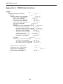
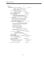
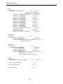
MMU Data structure
Appendix 4: MMU Data structure.
RECORD (
rack:
{ R.1
}
RECORD (racknumber: INTEGER,
{ R.1.1
}
advanced:
{ R.1.2
}
RECORD (manager index: INTEGER,
{ R.1.2.1 }
system clock: LONGINTEGER,
{ R.1.2.2 }
last log entry: INTEGER,
{ R.1.2.3 }
screen refresh time: INTEGER,
{ R.1.2.4 }
renumber racks: FUNCTION,
{ R.1.2.5 }
reset eerom strings: FUNCTION,
{ R.1.2.6 }
clear logfile: FUNCTION,
{ R.1.2.7 }
debug info:
{ R.1.2.8 }
RECORD (send traps: ENUMERATE (off,on),
{ R.1.2.8.1 }
last trap number: INTEGER,
{ R.1.2.8.2 }
upload new MMU software: INTEGER, { R.1.2.8.3 }
upload new modem software: INTEGER, { R.1.2.8.4 }
debug info on/off: INTEGER,
{ R.1.2.8.5 }
debug info modem: INTEGER,
{ R.1.2.8.6 }
task list: FUNCTION,
{ R.1.2.8.7 }
watchdog timers: FUNCTION,
{ R.1.2.8.8 }
test function.: FUNCTION
{ R.1.2.8.9 }
)
rack f.busy:
{ R.1.2.9 }
RECORD (rack f.busy off: FUNCTION,
{ R.1.2.9.1 }
rack f.busy on: FUNCTION,
{ R.1.2.9.2 }
rack f.busy control off: FUNCTION, { R.1.2.9.3 }
rack f.busy control on: FUNCTION
{ R.1.2.9.4 }
)
),
software version: CHARSTRING,
{ R.1.3
}
organisation name: CHARSTRING,
{ R.1.4
}
manager name: CHARSTRING,
{ R.1.5
telephone (home): CHARSTRING,
{ R.1.7
}
serial number: CHARSTRING,
{ R.1.8
}
),
46
}
MMU Data structure
modem:
ARRAY [16]:
{ R.2
}
RECORD (modem group: ENUMERATE
{ R.2.X.1 }
(group 1, group 2, group 3, group 4,
group 5, group 6, group 7, group 8,
group 9, group 10),
state: ENUMERATE (available,reserved,online,
online,not installed),
{ R.2.X.2 }
power: ENUMERATE (off,on),
{ R.2.X.3 }
f.busy: ENUMERATE (off,on),
{ R.2.X.4 }
mode: ENUMERATE
{ R.2.X.5 }
(-,?,Bell 103,Bell 212A, Bell 208,V21,
V22,V22bis,V23,V26A,V26bis,V27ter,V29,V17,
V32,V32bis,V32 TCM,V33,VFC,V34,V34bis),
bps: ENUMERATE
{ R.2.X.6 }
(-,?,300,600,1200,1275,2400,4800,7200,
9600,12000,14400,16800,19200,21600,
24000,26400,28800,30000,31200,32400,
33600,34800,36000,37200,38400),
disconnect reason: ENUMERATEb
{ R.2.X.7 }
(-,normal,2.,3.,carrier loss,
no EC at remote,no feature negot.response,
remote is sync only,framing incompatible,
no protocol in common,
bad feature negot.response,
no sync info from remote,
“normal, initiated by remote”,
retransmission limit reached,
protocol violation,.,.,.,.,
inactivity timeout,no dialtone,no answer,
busy,key abort,failed to connect)
error correction: ENUMERATE
{ R.2.X.8 }
(-,none,lapm,mnp4,mnp5,
V42bis lapm,V42bis mnp4),
quality: INTEGER,
{ R.2.X.9 }
signals: INTEGER,
{ R.2.X.10 }
reset: ENUMERATE (not active,resetting ...),
{ R.2.X.11 }
factory reset: ENUMERATE,
{ R.2.X.12 }
(not active,resetting ...)
initialize: FUNCTION,
{ R.2.X.13 }
analyse serial connection:
{ R.2.X.14 }
RECORD (analyse TXD: FUNCTION,
{ R.2.X.14.1}
analyse RXD: FUNCTION
{ R.2.X.14.2}
),
direct connect: FUNCTION
{ R.2.X.15 }
),
47
MMU Data structure
group:
ARRAY [10]:
RECORD (speed: ENUMERATE,
{ R.3
}
{ R.3.X.1 }
(300,1200,2400,4800,9600,
19200,38400,57600,115200)
auto config. : ENUMERATE (off,on),
{ R.3.X.2 }
initstring A: CHARSTRING,
{ R.3.X.3 }
initstring B: CHARSTRING,
{ R.3.X.4 }
initstring C: CHARSTRING,
{ R.3.X.5 }
initstring D: CHARSTRING,
{ R.3.X.6 }
initstring E: CHARSTRING,
{ R.3.X.7 }
initstring F: CHARSTRING,
{ R.3.X.8 }
initstring G: CHARSTRING,
{ R.3.X.9 }
initstring H: CHARSTRING,
{ R.3.X.10 }
initstring I: CHARSTRING,
{ R.3.X.11 }
initstring J: CHARSTRING,
{ R.3.X.12 }
auto line busy: ENUMERATE (off,on),
{ R.3.X.13 }
ADB delay: INTEGER,
{ R.3.X.14 }
initialize: FUNCTION,
{ R.3.X.15 }
upload new software: FUNCTION
{ R.3.X.16 )
),
management:
ARRAY [20]:
{ R.4
}
RECORD (name: CHARSTRING
{ R.4.X.1 }
password: PASSWORD
{ R.4.X.2 }
user class: ENUMERATE (supervisor,manager, { R.4.X.3
ADB editor,technician)
),
autodialback:
ARRAY [2000]:
{ R.5
}
RECORD (name: CHARSTRING ,
{ R.5.X.1 }
password: PASSWORD,
{ R.5.X.2 }
areacode: CHARSTRING,
{ R.5.X.3 }
telephone: LONGINTEGER,
{ R.5.X.4 }
group: ENUMERATE (group 1, group 2, group 3, { R.5.X.5
group 4, group 5, group 6,
group 7,group 8, group 9, group 10)
),
logfile:
ARRAY [8000]:
RECORD (event: LOGFILE_INTEGER ),
{ R.6
to previous rack: FUNCTION,
}
{ R.6.X.1 }
{ R.7
to next rack: FUNCTION,
}
{ R.8
logout: FUNCTION
{ R.9
).
48
}
}
}
}
Technical specifications
Appendix 5: Technical specifications.
The MultiTRON can contain a maximum of 16 modems.
A maximum of 15 racks can be coupled.
Each MMU can store 2000 auto dialback names (PCB MMU 2295).
Older MMU’s (PCB MMU 3994) can store a maximum of 1000 ADB
names.
Each MMU can store 8000 micro events in a logfile (PCB MMU 2295).
Older MMU’s (PCB MMU 3994) can store a maximum of 4000 micro
events.
Dimensions
The MultiTRON 19’’ rack system is 19’’ wide and 4 units high.
Operational reliability
Various safeguards have been included in the rack system to increase
operational reliability:
•
•
•
•
•
On the absence or non-functioning of the MMU the modems
continue to function as normal.
Each modem has its own stabilised power supply.
The power supply transformer possesses two secondary windings,
each supply power to 8 modems via two rectifiers. If a winding or
rectifier should ever fail, half of the modems will continue to
function normally.
The MMU is powered by both transformer windings, and will remain
operational providing only one of the two power supplies has
failed.
The processors in the modems and the MMU are monitored by a
watchdog system, which will reset the processor concerned if any
abnormal program results are detected.
Fuses
Two fuses (10 A, slow) are located on the rear of the backplane. Fuse 1
is for the transformer winding that supplies power to modems 1 to 8,
Fuse 2 is for the winding powering modems 9 to 16. A primary 1 A fuse
is incorporated in the mains input.
Power consumption
The power consumed by 1 rack with 16 modems in full operation
amounts to approximately 75 WATT.
49
Technical specifications
Connectors
DB9 female connector on the front of the MMU. 19200 BPS. (Terminal connection.)
CCITT No. Direction Name
102
103
104
105
106
107
108
5
3
2
7
8
6
4
109
125
1
9
IN
OUT
IN
OUT
OUT
IN
OUT
Signal Ground
Transmitted data
Received data
Request to send
Clear to send
Data set ready
Data terminal
ready
Data set ready
not connected
Abbreviatio
n
GND
TxD
RxD
RTS
CTS
DSR*
DTR
DCD*
* These two signals are coupled in this connector.
DB9 female connector on the rear of the rack (uppermost connector). 115200 BPS.
(Terminal connection)
CCITT No. Direction Name
102
103
104
105
106
107
108
5
3
2
7
8
6
4
IN
OUT
IN
OUT
OUT
IN
109
125
1
9
OUT
OUT
Signal Ground
Transmitted data
Received data
Request to send
Clear to send
Data set ready
Data terminal
ready
Data set ready
- 10 volt
Abbreviatio
n
GND
TxD
RxD
RTS
CTS
DSR*
DTR
DCD*
RI
* These two signals are coupled in this connector.
DB9 male connector on the rear of the rack (lowest connector). 115200 BPS.
(Modem connection)
CCITT No. Direction Name
102
103
104
105
106
107
108
5
3
2
7
8
6
4
OUT
IN
OUT
IN
IN
OUT
109
1
IN
125
9
IN
Signal Ground
Transmitted data
Received data
Request to send
Clear to send
+10 Volt
Data terminal
ready
Data carrier
detect
- 10 volt
Abbreviatio
n
GND
TxD
RxD
RTS
CTS
DSR
DTR
DCD
RI
50