1
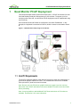
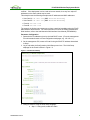
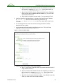
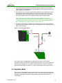
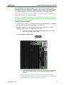
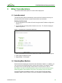
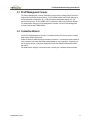
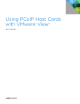
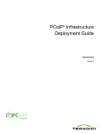
PCoIP® Multi-Monitor
Deployment Guide
TER0905009
Issue 2
PCoIP Multi-Monitor Deployment Guide
Teradici Corporation
#101-4621 Canada Way, Burnaby, BC V5G 4X8 Canada
p +1 604 451 5800 f +1 604 451 5818
www.teradici.com
The information contained in this document represents the current view of Teradici Corporation as of the date of publication.
Because Teradici must respond to changing market conditions, it should not be interpreted to be a commitment on the part of
Teradici, and Teradici cannot guarantee the accuracy of any information presented after the date of publication.
This document is for informational purposes only. TERADICI MAKES NO WARRANTIES, EXPRESS, IMPLIED OR
STATUTORY, AS TO THE INFORMATION IN THIS DOCUMENT.
Complying with all applicable copyright laws is the responsibility of the user. Without limiting the rights under copyright, no
part of this document may be reproduced, stored in or introduced into a retrieval system, or transmitted in any form or by any
means (electronic, mechanical, photocopying, recording, or otherwise), or for any purpose, without the express written
permission of Teradici Corporation.
Teradici may have patents, patent applications, trademarks, copyrights, or other intellectual property rights covering subject
matter in this document. Except as expressly provided in any written license agreement from Teradici, the furnishing of this
document does not give you any license to these patents, trademarks, copyrights, or other intellectual property.
© 2009 Teradici Corporation. All rights reserved.
Teradici, PC-over-IP, and PCoIP are registered trademarks of Teradici Corporation.
The names of actual companies and products mentioned herein may be the trademarks of their respective owners.
TER0905009 Issue 2
1
PCoIP Multi-Monitor Deployment Guide
Revision History
Version
Date
Description
1
Jul 09, 2009
Initial Release
2
Aug 24, 2009
Clarified the reason of disabling WOL on the slave
Host Card in Section 2.1
TER0905009 Issue 2
2
PCoIP Multi-Monitor Deployment Guide
Contents
REVISION HISTORY ...................................................................................................... 2
CONTENTS .................................................................................................................... 3
TABLE OF FIGURES ..................................................................................................... 4
DEFINITIONS ................................................................................................................. 5
INTRODUCTION............................................................................................................. 6
1
QUAD MONITOR PCOIP DEPLOYMENT................................................................ 7
1.1
Host PC Requirements ...................................................................................................................... 7
1.2
Host Cards Installation ....................................................................................................................... 8
1.3
Portal Installation................................................................................................................................ 8
1.4
Network Configuration and Connect .................................................................................................. 8
2
ADVANCED CONFIGURATION............................................................................. 12
2.1
Remote Power Management ........................................................................................................... 12
2.2
Standalone Mode ............................................................................................................................. 13
3
OTHER CONSIDERATIONS .................................................................................. 16
3.1
Auto-Reconnect................................................................................................................................ 16
3.2
Remoting More Monitors.................................................................................................................. 16
3.3
PCoIP Management Console........................................................................................................... 17
3.4
Connection Brokers.......................................................................................................................... 17
TER0905009 Issue 2
3
PCoIP Multi-Monitor Deployment Guide
Table of Figures
Figure 1-1 Quad Monitors Setup Using Two PCoIP Kits .................................................... 7
Figure 1-2: Portal Initial Setup ............................................................................................ 9
Figure 1-3: Host Card Initial Setup.................................................................................... 10
Figure 2-1 Disable WOL Header....................................................................................... 12
Figure 2-2: Host Card Power Button................................................................................. 13
Figure 2-3 Standalone Mode Header................................................................................ 14
Figure 2-4 Floppy Drive Power Connector ....................................................................... 15
Figure 3-1: Portal Session Configuration Web Page ........................................................ 16
TER0905009 Issue 2
4
PCoIP Multi-Monitor Deployment Guide
Definitions
AC
Alternating Current
ATX
Advanced Technology Extended
BIOS
Basic Input/Output System
DHCP
Dynamic Host Configuration Protocol
DNS
Domain Name System
DVI
Digital Visual Interface
IP
Internet Protocol
MAC
Media Access Control
NIC
Network Interface Card
OS
Operating System
OSD
On Screen Display
PC
Personal Computer
PCIe
Peripheral Component Interconnect Express
®
PC-over-IP
®
Personal Computer over Internet Protocol
PCoIP
see PC-over-IP
PCoIPMC
PCoIP Management Console
PCoIP Host
Host side of PC-over-IP system
PCoIP Portal
Portal or desktop side of PC-over-IP system
RDP
Remote Desktop Protocol
USB
Universal Serial Bus
WOL
Wake-on-LAN
TER0905009 Issue 2
5
PCoIP Multi-Monitor Deployment Guide
Introduction
This document provides step-by-step instructions on deploying a basic multi-monitor
PCoIP deployment including setting up a quad monitor system using two PCoIP Host
Cards in a host PC along with two Portals. The document also describes how users can
install more than two pairs of Host and Portal devices for a single PC to support more
than four monitors. It also describes other considerations that should be taken into
account for this deployment.
TER0905009 Issue 2
6
PCoIP Multi-Monitor Deployment Guide
1
Quad Monitor PCoIP Deployment
This section describes a basic quad monitor deployment. A PCoIP kit consists of a Host
Card and Desktop Portal pair and supports up to two monitors. To support up to four
monitors on the client side, a multi-monitor PCoIP deployment can be implemented using
two PCoIP kits.
Here the Hosts Cards and Portals are configured to use static IP addresses. In this
example, the keyboard is connected to Portal A, while the mouse is connected to Portal
B.
Figure 1-1 Quad Monitors Setup Using Two PCoIP Kits
1.1 Host PC Requirements
The host PC needs two graphics cards with two DVI ports on each card. Alternatively, a
quad monitor graphics card can be used. The motherboard must have two available
PCIe (minimum x1) slots for the two Host Cards.
Note: Be sure your host PC with two graphics cards can support up to four monitors
without the use of PCoIP and that there are two available PCIe slots for the Host Cards
before proceeding.
Note: It may be possible to add additional PCoIP Host cards when no PCIe slots are
available. See Section 2.2 for more information.
TER0905009 Issue 2
7
PCoIP Multi-Monitor Deployment Guide
1.2 Host Cards Installation
This section outlines the installation using Host Card A as the master and Host Card B as
the slave.
Host Card A, the master, can be used for remote power management. If you wish to
enable power management, refer to Section 2.1 below for more information.
Host Installation Process
1. Power down your host PC and unplug the AC power cord.
2. Install two graphics cards with two DVI ports each that support a total of up to four
monitors. (Alternatively install one quad graphics card)
3. Note down the MAC address on Host Card A and install in an available PCIe slot.
4. Note down the MAC address on Host Card B and install in an available PCIe slot.
5. Connect DVI cables from graphics card A to Host Card A, and graphics card B to Host
Card B.
6. Connect Ethernet cable from the two Host Cards to a local DHCP network. (It is
recommended to use a small DHCP router for initial configuration, as this will make
determining the DHCP IP addresses easy.)
7. Reconnect the AC power cord, and power on the host PC.
1.3 Portal Installation
This section outlines the installation using Portal A as the master and Portal B as the
slave.
Portal Installation Process
1. Connect Portal A to two monitors and connect keyboard.
2. Connect Portal B to two monitors and connect mouse.
3. Connect Ethernet cable from the two Portals to a local DHCP network. (It is
recommended to use a small DHCP router for initial configuration, as this will make
determining the DHCP IP addresses easy)
4. Connect the AC power cords, and power on the Portals.
1.4 Network Configuration and Connect
This section describes configuring the Host Cards and Portals to use static IP addresses
using the PCoIP Administrative Web Interface. Using static IP addresses is
recommended as Host Discovery mode is not intended for production deployments due
to the limitation of the Portal displaying only 10 PCoIP Host Cards.
The network parameters can be reconfigured using a management PC. Connect a
management PC to the local network of the PCoIP Hosts and Portals. Alternatively, you
can connect the quad monitor PC NIC to the same network as the Hosts and Portals and
use it as the management PC.
Before continuing, decide on four IP addresses to use for this deployment. If the
deployment is to be used on the main network, you must configure your router or switch
to reserve IP addresses in your network for the PCoIP devices to avoid IP address
TER0905009 Issue 2
8
PCoIP Multi-Monitor Deployment Guide
conflicts. If the deployment is to be used on its own network, then any four unique IP
addresses on the same subnet may be used.
This example uses the following example static IP addresses and MAC addresses:
• Host Card A: 192.168.1.200 (MAC: AA-AA-AA-AA-AA-AA)
• Host Card B: 192.168.1.201 (MAC: BB-BB-BB-BB-BB-BB)
• Portal A: 192.168.1.202
• Portal B: 192.168.1.203
The example in this document assumes you have a working knowledge using the PCoIP
Administrative Web Interface. For more information on use in the PCoIP Administrative
Web Interface, refer to the Administrative Web Interface User Manual (TER0606004).
Parameter Configuration
1. Determine the IP addresses given by the local DHCP router. (From the management
PC web browser browse to router configuration web pages, e.g. 192.168.1.1.)
2. On the management PC, browse to Portal A using the DHCP IP address determined
in Step 1.
3. Log in and select the Configuration->Initial Setup menu item. The Initial Setup
webpage for the Portal is shown in Figure 1-2
Figure 1-2: Portal Initial Setup
4. Configure Portal A using the Initial Setup webpage:
a. Step 1: If using audio, enable HD audio.
TER0905009 Issue 2
9
PCoIP Multi-Monitor Deployment Guide
b. Step 2: Uncheck Enable DHCP and enter the IP address you want to use
for Portal A, for example, 192.168.1.202. Enter Subnet Mask (e.g.
255.255.255.0) and Gateway (e.g. 192.168.1.1).
c.
Step 3: Select PCoIP for Session Type and Identify Host by IP address.
Enter Host A’s static IP address and MAC address, e.g. 192.168.1.200
and AA-AA-AA-AA-AA-AA.
d. Select Apply to accept the changes made. You can restart the Portal
5. Configure Portal B by repeating Steps 1-5 except using Portal B’s new IP address,
e.g. 192.168.1.203 and Host Card B’s networking information, e.g.
192.168.1.201 the BB-BB-BB-BB-BB-BB. Also, if you want audio, enable it only
on Portal A.
6. On the management PC, browse to Host Card A using the DHCP IP address
determined in Step 1 above.
7. Log in and select the Configuration->Initial Setup menu item. The Initial Setup
webpage for the Host Card is shown in Figure 1-3.
Figure 1-3: Host Card Initial Setup
8. Configure Host Card A using the Initial Setup webpage:
a. Step 1: If using audio, enable HD audio (only enable Vista 64-bit mode if
using Windows Vista 64.)
b. Step 2: Uncheck Enable DHCP and enter the IP address you want to use
for Host Card A, for example, 192.168.1.200. Enter Subnet Mask
(e.g. 255.255.255.0) and Gateway (e.g. 192.168.1.1).
c.
TER0905009 Issue 2
Step 3: Be sure Accept Any Portal is enabled. (If you disable Accept Any
Portal, you must enter Portal A’s MAC address.)
10
PCoIP Multi-Monitor Deployment Guide
d. Step 4: Select Apply to accept the changes made. Do not restart the
Host PC.
9. Configure Host Card B by repeating Steps 6-8 except using Host Card B’s DHCP
address to configure it to the new static IP address, e.g. 192.168.1.201.
10.Shutdown and restart the PC using the PC power.
Establish PCoIP Session
1. On Portal A, press the Enter key on the keyboard to establish a PCoIP session to
Host Card A.
2. On Portal B, click the Connect button using the mouse to establish a PCoIP session to
Host Card B.
3. Done!
TER0905009 Issue 2
11
PCoIP Multi-Monitor Deployment Guide
2
Advanced Configuration
This section outlines configuration for more advanced features of remote power
management and Standalone mode.
2.1 Remote Power Management
The PCoIP Host Card and Portal optionally enable remote power management, i.e. you
can power on/off and wake the PC using the Portal.
Enabling power management requires connecting a cable from the Host Card to the PC.
Note: Some Host PCs may not be able to support multiple PCoIP Host Cards and power
management (powering/waking from the Portal) due to standby auxiliary power. If the
Host PC does not have enough standby auxiliary power, then power management will not
be available to use at the Portal.
Configuring Power Management
1. Configure the Wake-on-LAN header on the PCoIP Host Cards.
a. By default, the Wake-on-LAN (WOL) header is enabled and a jumper is
set on pin 2-3. Since Host Card A is used for remote power
management, be sure WOL is enabled and the jumper is set on pin 2-3
on the WOL header.
b. Since Host Card B is not used for remote power management, WOL
must be disabled by setting the jumper on pin 1-2 on the Disable WOL
header. Doing so reduces its 3.3Vaux power consumption.
Note: This WOL feature is different from that available on the PC motherboard
and PC BIOS.
Figure 2-1 Disable WOL Header
TER0905009 Issue 2
12
PCoIP Multi-Monitor Deployment Guide
2. Connect the white end of the Host Card Power Button Cable to the Power Button
Cable Connector on the Host Card. The Power Button Cable Connector on the Host
card is labeled “JP5 PWR BTN”.
3. Disconnect the PC’s front-panel On/Off switch cable from the motherboard’s header,
and locate the Power On/Off signal pins. Connect the red wire on the Host Card
Power Button Cable to the positive terminal of the Power On/Off pin, and the black
wire to the negative terminal. The negative terminal is typically a ground pin.
Note: The location of the Power On/Off switch pins is different from one PC
motherboard to another. Please refer to your motherboard user manual for details. If
you have the connector inverted connected to the positive and negative terminal on
the PC motherboard, you will not be able to power up the PC.
4. If possible, connect the PC’s front-panel On/Off switch cable to the 2-pin header on
the Host Card Power Button Cable. If this is not possible, the PC’s front-panel On/Off
Switch will be disabled.
Figure 2-2: Host Card Power Button
Since Host Card A is configured as the master that provides the remote power
management feature and Portal A is connected to Host Card A, you can use Portal A for
remote power management. If you want to remotely power on the host PC, press the
Remote PC Power Button on Portal A or a key on the keyboard connected to Portal A.
2.2 Standalone Mode
If there is only one available PCIe slot for the Host Cards, reserve it for the master Host
Card and do not install Host Card B in the PCIe slot. You can configure Host Card B in
Standalone mode and do not have to install the slave Host Card into the host PC’s
motherboard.
TER0905009 Issue 2
13
PCoIP Multi-Monitor Deployment Guide
You can install the Host Card somewhere inside or outside of the host PC. The Host
Card draws power from a floppy drive connector (+5V/+12V) of your ATX power supply in
your host PC. The slave PCoIP Host Card and Portal are used for video transmission
only (USB and audio are not supported when a Host Card is in Standalone mode).
Note: If there is not a free PCIe slot available for Host Card B, although not ideal, Host
Card B can be installed in Standalone mode.
Warning: If using Standalone mode, be sure the Standalone Host Card is well secured to
avoid physical/electrical damage and safety issues. Do not use Standalone mode unless
the Host card can be secured safely!
Configuring Standalone Mode
1. The slave Host Card can be configured in Standalone mode. Standalone mode allows
the Host Card to operate without installation in a PCIe slot.
By default, Standalone mode is disabled and the jumper is set to pin 2-3 of the
Standalone Mode Header. To enable Standalone mode:
a. Set the jumper to pin 1-2 of the Standalone Mode header. See Figure
2-3 for the pin number of this header.
Figure 2-3 Standalone Mode Header
b. Connect the floppy drive power connector. Note that the Host card draws
power from an external power supply through the floppy drive power
connector.
Warning: Be sure the floppy drive connector is connected in the proper
direction as shown in Figure 2-4. Also, be sure the Host Card is properly and
safely located to prevent short circuiting the Host Card.
TER0905009 Issue 2
14
PCoIP Multi-Monitor Deployment Guide
Figure 2-4 Floppy Drive Power Connector
TER0905009 Issue 2
15
PCoIP Multi-Monitor Deployment Guide
3
Other Considerations
This section outlines other options for a multi-monitor deployment.
3.1 Auto-Reconnect
The Auto-Reconnect feature automatically reconnects PCoIP sessions when they are
disconnected by either network or power issues without user interaction.
Enabling Auto-Reconnect
1. On the management PC, browse to Portal A using the static IP address configured in
Section 1.4.
2. Log in and select the Configuration->Session menu item. The Session webpage is
shown in Figure 3-1.
Figure 3-1: Portal Session Configuration Web Page
3. Click on the Enable Auto-Reconnect check box to enable the Auto-Reconnect option.
4. Select Apply to update the Portal.
5. Repeat Steps 1-4 for Portal B.
3.2 Remoting More Monitors
Quad monitor PCoIP deployment instructions are discussed in Section 1. In addition, you
can use more PCoIP Host/Portal pairs to remote more monitors. For example, Portal A
and Host Card A; Portal B and Host Card B; Portal C and Host Card C, and etc.
Note: Before you add more Host/Portal pairs to remote more monitors, be sure that the
additional graphics cards installed to the host PC can properly drive multi-monitors.
If no free PCIe slots are available in the PC, you can use the PCoIP Host Card in
Standalone Mode. Refer to Section 2.2 for more information on Standalone Mode.
TER0905009 Issue 2
16
PCoIP Multi-Monitor Deployment Guide
3.3 PCoIP Management Console
The PCoIP Management Console (PCoIPMC) can be used to manage PCoIP devices in
larger multi-monitor PCoIP deployments. The PCoIPMC allows easy PCoIP pairings as
well as parameter configuration (e.g. USB permissions, bandwidth settings, etc.) for
various users groups. The PCoIPMC can be used with or without a Connection Broker.
For details about using the PCoIP Management Console, refer to PCoIP Management
Console User Manual (TER0812002).
3.4 Connection Brokers
Like the PCoIP Management Console, a connection broker can also be used in a larger
multi-monitor PCoIP deployment.
Unlike the static IP address pairings described in Section 1.4 connection brokers allow for
more dynamics Host Card and Portal pairings based on user credentials. Depending on
the connection broker, it may also manage the slave Host Cards/Portals sessions with
the master.
For details about using the connection broker, contact your connection broker provider.
TER0905009 Issue 2
17