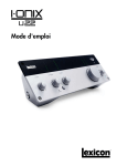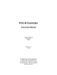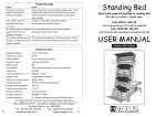
1
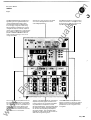
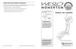
.c om ua ls tM an The Westinghouse GPC 1500A Controller is a multi-loop or unit controller that can oper ate independently or within a Distributed Control Sytstem. Whether used in a Distrib uted Control System or independently, it is an autonomous controller. Control system configurations are stored in its memory. Each GPC 1500A can control complex sys tems consisting of as many as six loops with four controlled outputs. These con trolled outputs are continuously tracked by its track and hold board, which insures safe process operation under abnormal control ler malfunction. lP ar Typical applications include entire boiler, soaking pit, reheat furnace, process heater and pipeline override control systems. Other applications include multi-probe averaging and sulfur emissions monitoring. ca This microprocessor-based system is specif ically designed to utilize a building block concept, which permits easy configuration of a wide range of complex control applica tions. A flexible set of blockware allows control systems to be designed to meet spe cific customer applications without com puter programming knowledge. External hardware is not required to enter new configurations. • tri • D o Features • • • • Blockware designed with 55 different control algorithms Scan rate of 4 times/second Six Automatic/Manual stations Four controlled outputs backed up with track and hold logic Four AIM stations with separate increase .E • lec The GPC 1500A is designed with adequate memory and programmable capability to perform as a mUlti-loop controller, as well as an integral part of a Distributed Control System. Membrane Front Panel that is Locked Closed in Lock Position decrease pushbuttons and output bar • • • • • • type O2 and SOx Analyzer packages Available with Canadian Standards Asso elimination of mechanical switches. Other benefits include highly visible bargraph indi cations for loop outputs and lower mainte nance/calibration costs due to the elimination of incandescent lamps and mechanical pushbuttons. In addition, the membrane switches are easily activated with an operating force of six to eight First out eight alarm annunciator Built in diagnostics with error display 4V2 digit display for loop and configura tion data and error message display Process variables and set-points dis played in either percent or engineering • units Configurations and tuning directly from front panel Customized labels for loop and alarm identification Optional cassette tape unit available for Membrane Front Panel configuration loading the electronic enclosure. ww • The panel utilizes highly reliable membrane • w • Key-lock protection of configuration and tuning parameters Special function blocks allow automatic recalibration of all Westinghouse probe graph indicators Four trend outputs • ciation (CSA) approval. The membrane front panel makes the GPC 1500A suited for harsh industrial environ ments since it is sealed and lockable, pre venting damage from dirt and grime buildup and prevents unauthorized entry to switch technology. This technology estab lishes more reliable electronics due to sin gle printed circuit board construction and ounces per square inch. .c om Descriptive Bulletin 106-410 Page 2 o The DISPLAY pushbutton is used to select the process vanable, local setpoint or bias, remote set point, or percent output of the loop Identified by the LOOP LEOs. ua ls An eight alarm first out annunciator panel with customized legends and an alarm acknowledge pushbutton, .E lec tri ca lP ar tM an The INCR-DECR pushbuttons under the 4% digit LED (light emitting diode) display will change the displayed variable. The key switch prevents unauthorized personnel from changing configuration and tuning data. Examples of variables which may be changed are set points and loop outputs in manual. The loop pushbutton cycles through the loop LEOs to identify the loop being dis played. The SERVICE MANUAL LED IS lit when the analog tracking circuitry is con trolling the outputs, The four controlled outputs are indicated on separate output bargraph indicators. Each primary loop has its own backlit Auto/Man ual pushbutton and separate increase The two pushbuttons with adjacent loop LEOs may also be configured to be Auto/ Manual pushbuttons, and serve as auxiliary loops internal to a control system. decrease pushbuttons. The loop LEDs above the meters are used by the LOOP pushbut ton to select the loop being displayed on ww w The four auxiliary backlift pushbuttons may be configured to select percent or engineer ing units, perform automatic oxygen calibra tion, or serve as remote/local pushbuttons. • o o The NUMBER AND VALUE pushbuttons identify configuration information and are used along with the shared INCR·DEeR pushbuttons to enter configuration and tuning data. the digital readout. The customized loop legends are used to specify the process var iable and its engineering units. Ju1V.1988 .c om Descriptive Bulletin 106-410 Page 3 The Model GPC 1500A can accept 9 contact inputs, 7 analog inputs, 8 analog outputs and 7 relay or TTL outputs. The unit can Major Electronic Subassemblies ua ls handle either current or voltage I/O. The self-contained switching power supply oper ates on line voltage. An optional 24 VDC external auxiliary power connection will (CMR-NEUTRAL-MANUAL) switch located on the track and hold circuit board. The operator retains manual control, with indica tion of the outputs through the increase decrease pushbuttons adjacent to the out put bargraph indicators. Service manual STATUS is indicated by an LED on the front panel. maintain controlled outputs (outputs 1-4) during servicing or in the event of 115 volt power loss. The control configuration is stored in bat tery backed up CMOS memory on the inter face card. The battery is trickle charged Six major electronic sub-assemblies make up the Model GPC 1500A. They are the during normal operation, and will protect the contents of CMOS memory for approxi mately 3 months in case of loss of power. A switch and an LED adjacent to the battery can be used to check the condition of the battery. The actual configuration is entered into CMOS memory from the front panel an power supply card. the analog I/O card, the processor card, the interface card, the track and hold service manual board. and the front panel assembly. tM The track-and-hold logic designed into the Model GPC 1500A eliminates the need for but can also be entered via a cassette tape or a computer station which may be part of the control system. Configuration and tun ing are under key-lock protection. ar separate analog backup stations. During serviCing, the unit can be switched to the tracking circuitry by means of the Computer Mode Request-Neutral-Service manual lP 1/0 BOARD tri ca POWER SUPPLY BOARD lec .E COMPUTER SERVICE MANUAL SWITCH �-----FRONT PANEL DRIVER BOARDS INTERFACEI MEMORY TRACK & HOlD LOGIC BOARDS ww w BOARD July, 1988 RESET BUTTON MEMORY BATTERY TEST SWITCH & LED .c om Descriptive Bulletin 106-410 Page 4 ANALOG INPUT ua ls LEAD-LAG The ALARM block interfaces the alarm status of 8 logic inputs to the front panel LEOs, DIGITAL DISPLAY INTERFACE The DISPLAY block identifies the process variable, local set point or bias, remote set point, and output of one of the six loops in the controller. This information can then be accessed by the loop and display pushbuttons on the front panel. Control Functions ar AUTO/MANUAL STATION The AIN block filters the input Signal from the rear panel and converts it to a -10% to 110% analog variable, The LED LAG block provides dynamic com pensation to an analog signal. VELOCITY LIMIT an Process and Operator Interface ALARM tM Blockware Configuration BLOCKWARE refers to the set of pre-pro grammed control algorithms in the Model GP C 1500A. Control Systems are imple mented by interconnecting the control algo rithms, or control blocks, to perform the desired control functions. Control blocks do not reside in pre-defined slots. Blocks are evaluated sequentially by block number. Within certain memory limitations which will be flagged as configuration errors, a control system may use any block in the BLOCKWARE library any number of times. Configuration information is stored in bat tery backed up CMOS memory. The VUM block limits the rate of change o f its output. TRANSFER The transfer block transfers control between two analog signals. VELOCITY LIMITED TRANSFER lP The AIM block generates the internal controlled output for one of the six loops in the unit. LOCAL SET POINT OR BIAS ca ANALOG OUTPUT The AOUT block transfers its' input variable The TUM block provides bumpless transfer between two analog inputs at independently adjustable rates. COMPARATOR The LSP/B block generates the local set point or bias to a loop controller. PIDAM CONTROLLER REMOTE CONTACT INPUT tri to an output port. The CMP block compares two analog inputs to develop the digital output. lec The PIDAM controller combines the function of PID controller and AIM station in one block, HIGH/LOW STATUS PID CONTROLLER The Rei block transfers a contact input status to the control system, The output of the H/L block is a logical value .E RELAY OUTPUT The PID controller block may be used with other control blocks to implement feed forward control, ratio control, cascade control, or standard 3-mode control. which represents the alarm status of the analog input variable. TIMER ADAPTIVE CONTROLLER w The ROUT block energizes one of the output relays. ww PUSHBUTTON The PB block develops a logic signal from one of the eight backlit pushbuttons, The PIDA controller can be configured to perform variable gain and override control. The TIMER block generates a pulse at an adjustable interval. PULSE INTEGRAL The INT block computes the integral of its' input, The PULSE block generates a variable width pulse, Julv, 1988 .c om Descriptive Bulletin 106·410 Page 5 LOW SELECT G § HIGH LIMIT Digital logic Functions OR EXCLUSIVE OR NOT LOW LIMIT § § ANALOG INVERTER GAIN 0 MULTIPLY DIVIDE ~ G DIFFERENCE SUMMATION G G LOGIC CONSTANT Autom atic Calibration lec The WSUM block computes the weighted SUM of two analog inputs. SQUARE ROOT .E The CASIFC block is used to transfer configuration data from the Model 1500 GPC to the optional ADPI cassette unit. UNACKNOWLEOGED ALARM CALIBRATE PUSHBUTTON The CALPB block is a special purpose block to interface a back lit pushbutton to the auto-calibration logic. CALOG The output of CALOG block is the slope of the logarithmic signal from an oxygen probe. tri WEIGHTED SUMMER LATCH ca 0 The output of the TREND block is equal to the output of the block number referenced. an ANALOG CONSTANT tM SAMPLE AND HOLD TREND CASSETTE INTERFACE ar B I I lP G Arithmetic Functions SCALE Miscellaneous Functions AND ua ls HIGH SELECT The output of the UNACK block is true if there are any acknowledged ala rms pending. SERVICE MANUAL The SERV block output is true if the unit is in the service manual mode. CALEX NO OPERATION The CALEX block linearizes the logarithmic signal from an oxygen probe. During auto calibration the output is held constant. CALSL The NOP block reserves space for future expansion of a control system. ENDOF FILE w FUNCTION GENERATOR FIX) block defines a four line segment function The output of the CALSL block is the slope of any oxygen probe with a linear output. CALIN The EOF block is the last block in any control implementation and Signals the end of the configuration data. ww generator. TIME FUNCTION The FIT) block can generate a four break point time ramp. July, 1988 The CALIN block scales the input signal from a linear oxgyen probe. During auto calibration the output is held constant. The GPC 1500A has extensive built-in diag nostics to identify hardware malfunctions and configuration errors. 106-410 Page 6 .c om Descriptive Bulletin How to Order Mechanical Enclosure: Type-Panel Mounting, %" thickness max. Approx. Case Size ........................... Height-7v." (19.1 cm) Depth-6%" (16.2 cm) Panel Cutout: . . . . . . . . . .. . . . ... . . . ... . . . . . . .. 79/,6"x67As" (19.2x16.1 cm) Access: ..................................... All circuit cards are accessible behind hinged front panel Weight: ..................... ....... ...... 25 Ibs. (11.4 Kg) Select the basic General Purpose Controller with desired options and accessories. Electrical Power Consumption ......................... Power ...................................... AC Line Voltage Interrupt .................... Scanning Rate .............................. Analog Signal Inputs ............... ........ Model 1500A General Purpose Digital Controller Number of VI1 Converters: Oty. o None . . . . . . . . . . . . . . . . . . . . . . • . . . . . 1 Voltage to Current Converter.... .... 2 Voltage to Current Converter. . . . . . . • 3 Voltage to Current Converter.. .. .... 4 Voltage to Current Converter.... .... an Environmental Temperature: ............................... 32-130°F (0-55°C) Relative Humidity: .......................... 0-90% non-condensing ua ls Specifications (j) 0 1 2 3 4 Cover Options: ar lP Contact Inputs .............................. Type,dry Rating 24VDC 2.5mA Maximum ................................ Nine ca Analog Signal Outputs ...................... 0-10VDC 4-20mA, 20-4mA Impedance ................................ Voltage < 10 ohms current, 4-20mA into 0 to 900 ohms, current terminates at signal common. Maximum ................. . ... .. ........ Eight 1 I I No Factory Configuration... .. .... .... 1 *Factory Configured . . 2 L ! r--- . . . . . . . . . . . . . .. Options: � � None.............................. l Cassette. ... ..... . ..... .... . .. ... .. 2 RS232 Termination Board........... " 3 ' RS422 Termination Board. ........... 4 General Purpose .................... 1 CSA Approved. . . . . . . • . . . . . . • . ...... 3 Example: Model 1500A-l1 1 1 1 This specifies a controller for enclosed panel mounting, with one 4-20 mA DC Output Module. Battery back-up for manual output, see DB 100- 5 1 3. Cable assembly for battery back-up required ... order PIN 3534B88. See PL 100-15 1. lec tri Contact or TIL Outputs ...................... 2 amps at 28VDC; 0.5 amps at 120VAC (for contact only) Maximum ................................ Seven (6 programmable, 7th indicates unit failure). Contact Style ............................. Two form C relays Four forms A or B relays . Oty: 1 Rear Terminal Cover ............... 1 1 Drip Cover and Rear Terminal Cover. . 2 tM 30VA 115 VAC ± 10%,50-60 Hz,1 amp two cycles without loss of control 4 times/second 1-5VDC,0-5VDC 2-10VDC,0-10VDC 4-20mA,0-20mA Impedance.................................. Voltage 900K ohms Current 250 ohms Accuracy ................................. 0.1% Maximum ................................ Seven .E Alarm Status................................ Eight LED Indicators front panel mounted flashing upon alarm, steady state upon acknowledge. Analog Backup .............................. Separately powered track and hold board automatically provides manual control in the event of power failure or micro processor failure for 4 primary outputs. Manual Output Battery Backup ............... Zero Drift RFI/EMI Rejection ........................... To 2000 volts with a rise time of 5ns. Memory Battery Backup... ... . ... . . ... . ........ . .. . .. (j) Equipment ordered utilizing this DB as refer ence will be supplied to the USA Standard design. Customers needing the EEC Standard design should request the EEC Standard DB and utilize its ordering data. = 3 months, provides battery backup to CMOS memory. ww w Cassette Interface An optional cassette unit is available to load and store configurations. Labels 8 alarm legends. ... ....... . ...... ........... 2 8 8 loop labels... ....... .......... .. .......... 2 14 4 pushbutton labels .... ............ ...... ... 4 lines each letters per line max. lines each letters per line max. characters max. July. 1988 : . . ' .c om Descriptive Bulletin 106-410 Page 7 The SAM A logic diag ram is representative of the control schemes that may be accopmplished with one Model GPC 1500A. The logic, as depicted, i s for a fully metered. cross-limited combustion control, with Oxygen Trim, two-element feedwater control plus furnace pressure control. Air Stea m Oil Drum Steam Furnace PT an ua ls LT Oxygen trim K I tM Oil Flow Controiler ar Fully Metered Cross Limited Combustion Control lP ;J; 2 Element Feedwater Control � ca � The BLOCKWARE diagram, illustrates the similiarity between the Westinghouse BLOCKWARE configuration scheme to the SAMA logic diagram above. To configure the GPC 1500A, computer programming knowledge is not needed. Steam Pressure Master Air Flow TG2 % 02 Furnace Pressure Steam Flow tri Oil Flow lec AIN (7) Furnace Pressure Controller MSTR-AIM Loop 6 AOUT(4 ww w .E Fully Metered Cross Limited Combustion Control Oil-AIM July, 1988 To 1.0. Fan Damper Furnace Pressure Control AOUT(3 Oxygen Trim To Feedwater Valve 2 Element Feedwater Control .c om Descriptive Bulletin 106-410 Page 8 Dimensions r -----+---16 1/121420.70 mrn! Min. tor Se rvlcmg ua ls 41.164 i16.27mml 6 1153mml 1-11-I Door I I -0 C Single Cutout \ W M ulhple Cutout Panel Cutout for Interlocking Cases Number of Cases Cutout Width W 6 7/16(163.32) 12 13/16(325.42) 3 19 118(485.78) 25 9/16(6 49.221 5 31 15/16(811.20) 6 38 5/16(973.12) 7 44 11/16(1135.05) 8 10 -- ---..- ./ /" / Panel Cutout Spacing .E 4 9 '- lec 1 2 " tri 79/16 I 1/32 1129.09) \ \ \ "- Connector s tl I I I I I : : r+---+ I 41/50 120.82mml 2x2 Angle Support Recommended ar • lP 1163.321 Max. Panel Thickness 3/4(19.05 rn m 1 ca I 67J16±1/32 • I---I I tM L.JIrFront View Trim Strips Shown in Place I --T---l an I -1--!����:To 51 1116(1296.97) 57 7/16(1458.97) 63 13/16(1620.82) DD_t DD_t C I &,. t Panel Cutout A Minimum Recommende /4(44.45) With Rigid Conduit 14(69.85) B 4 3/16(112.70) Notes: 1. Dimensions are in inches and(millimeters), for example: 6(153.0). 2. Unless otherwise specified, dimensional tolerance is ± 1/8(3.17). 3. Trim strips are supplied loose, to be used as necessary. 4. Nominal weight: 25Ibs. 8 oz. Standard W/protective covers ___ 26Ibs. 6 oz. 5. Panel cutouts shown are for standard Veritrak instruments. Additionally this in strument must have 3 inches minimum clearance top and bottom for ventilation. If microprocessors are mounted one above the another, 6 inches minimum clearance must be provided between them. w Westinghouse Electric Corporation Combustion Control Division 1201 North Main Street Orrville, Oh io , U.S,A. 44667 Toll Free: 1-800-628-1200 TELEX: 986340 Division Locations ww • Vienna - Austria • Shannon - Ireland • Villalba - Puerto Rico • Hamburg - Germany • Hitchin England • Sydney - Australia • Frankfurt - Germany • Zoetermeer - Holland • Milan -Italy • Madrid - Spain • Paris France If normal contacts with our sales and service operations fail to satisfy your needs, our representatives are available 24 hours at 1-800-433-6076, Printed in U.S.A. July. 1988