1
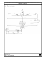
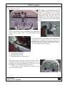
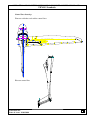
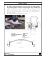
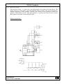
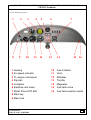
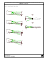
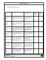
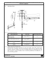
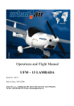
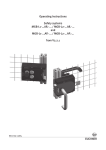
OPERATING AND MAINTENANCE MANUAL FOR ULTRALIGHT AEROPLANE
UFM-13 Lambada
1.
GENERAL
1.1.
Record of Revisions
Document No:
Date of issue: 24.09.2004
1-1
OPERATING AND MAINTENANCE MANUAL FOR ULTRALIGHT AEROPLANE
UFM-13 Lambada
1.2.
List of Effective Pages
Note
Latest issue of Maintenance Manual for ultralight airplane UFM 13 Lambada is 18.11.2003.
All pages of this document are effective.
Document No:
Date of issue: 24.09.2004
1-2
OPERATING AND MAINTENANCE MANUAL FOR ULTRALIGHT AEROPLANE
UFM-13 Lambada
1.3.
Table of contents
1. GENERAL ............................................................................... 1-1
1.1.
1.2.
1.3.
RECORD OF REVISIONS ............................................................................................................................................... 1-1
LIST OF EFFECTIVE PAGES ......................................................................................................................................... 1-2
TABLE OF CONTENTS .................................................................................................................................................. 1-3
2. TECHNICAL DATA .............................................................. 2-1
2.1. BASIC TECHNICAL DATA ............................................................................................................................................ 2-1
2.1.1.
Basic Dimensions ................................................................................................................................................. 2-1
2.1.2.
Power plant .......................................................................................................................................................... 2-2
2.2. THREE VIEW DRAWING ............................................................................................................................................... 2-4
2.3. TECHNICAL DESCRIPTION OF THE AIRPLANE............................................................................................................... 2-5
2.3.1.
Fuselage ............................................................................................................................................................... 2-5
2.3.2.
Wing..................................................................................................................................................................... 2-5
2.3.3.
Horizontal tail unit ( HTU ) ................................................................................................................................. 2-5
2.3.4.
Vertical tail unit ( VTU ) ...................................................................................................................................... 2-5
2.3.5.
Control system .................................................................................................................................................... 2-6
2.3.6.
Landing gear ........................................................................................................................................................ 2-8
2.3.7.
Power plant control ............................................................................................................................................. 2-9
2.3.8.
Fuel system .......................................................................................................................................................... 2-9
2.3.9.
Electrical system ................................................................................................................................................ 2-10
2.3.10.
Pittot-static system ............................................................................................................................................ 2-12
2.3.11.
Equipment .......................................................................................................................................................... 2-13
2.3.12.
Instrument panel ................................................................................................................................................ 2-14
2.3.13.
Interior & exterior placards .............................................................................................................................. 2-15
3. PERIODICAL INSPECTIONS AND INTERVALS ............ 3-1
3.1. PRE-FLIGHT INSPECTION............................................................................................................................................. 3-1
3.2. PERIODICAL INSPECTION INTERVALS .......................................................................................................................... 3-1
3.2.1.
Periodical inspections Sign off sheets .................................................................................................................. 3-1
3.2.2.
Periodical inspection after the first 25 hours and every 50 hours ..................................................................... 3-2
3.2.3.
Periodical inspection after every 100 flight hours ............................................................................................... 3-3
4. OPERATION AND MAINTENANCE ................................ 4-1
4.1.
4.2.
4.2.1.
4.2.2.
4.3.
4.3.1.
4.3.2.
4.4.
4.5.
4.5.1.
4.5.2.
4.6.
4.6.1.
4.6.2.
4.6.3.
4.6.4.
4.7.
4.7.1.
4.7.2.
OUTLINES ................................................................................................................................................................... 4-1
WEIGHT AND CENTER OF GRAVITY POSITION ............................................................................................................. 4-1
Empty weight determination ................................................................................................................................ 4-1
Operating C.G. range calculation ....................................................................................................................... 4-1
MECHANISM ADJUSTMENTS ....................................................................................................................................... 4-2
Torque moments ................................................................................................................................................... 4-2
Control Surface Deflections ................................................................................................................................. 4-3
PERMISSIBLE TOLERANCES ( PLAYS) .......................................................................................................................... 4-4
LUBRICATING CHART ................................................................................................................................................. 4-5
Recommended lubricants .................................................................................................................................... 4-5
Airframe lubrication fundamentals ...................................................................................................................... 4-5
BRAKE FLUID REFILLING, BRAKE SYSTEM BLEEDING, BRAKE PAD CLEARANCE ADJUSTAMENT .................................. 4-6
Brake fluid refilling .............................................................................................................................................. 4-6
Brake system bleeding .......................................................................................................................................... 4-6
Brake pad clearance adjustment .......................................................................................................................... 4-6
Brake pad replacement ........................................................................................................................................ 4-6
GROUND HANDLING ................................................................................................................................................... 4-7
Towing the airplane ............................................................................................................................................. 4-7
Parking the airplane ............................................................................................................................................ 4-7
Document No:
Date of issue: 24.09.2004
1-3
OPERATING AND MAINTENANCE MANUAL FOR ULTRALIGHT AEROPLANE
UFM-13 Lambada
4.7.3.
Tieing-down ......................................................................................................................................................... 4-7
4.7.4.
Jacking the airplane ............................................................................................................................................. 4-7
4.7.5.
Road transport ..................................................................................................................................................... 4-8
4.8. CLEANING AND CARE ................................................................................................................................................. 4-9
4.8.1.
Airplane care outlines .......................................................................................................................................... 4-9
4.8.2.
External surfaces cleaning ................................................................................................................................... 4-9
4.8.3.
Interior cleaning .................................................................................................................................................. 4-9
4.8.4.
Cockpit canopy cleaning ...................................................................................................................................... 4-9
4.9. AIRPLANE DISASSEMBLY .......................................................................................................................................... 4-10
4.9.1.
Wing disassembly ............................................................................................................................................... 4-10
4.9.2.
Wing assembly ................................................................................................................................................... 4-10
4.9.3.
HTU disassembly ............................................................................................................................................... 4-10
1.
Rematch the safety pin and unscrew the M8 screw ........................................................................................... 4-10
4.9.4.
HTU assembly .................................................................................................................................................... 4-10
5. REPAIRS.................................................................................. 5-1
5.1.
5.2.
5.3.
DAMAGE CLASSIFICATION .......................................................................................................................................... 5-1
RUDDER CONTROL CABLES REPLACEMENT................................................................................................................. 5-1
FIBREGLASS FAIRING AND COWLINGS REPAIRS........................................................................................................... 5-1
6. APPENDICES.......................................................................... 6-1
Document No:
Date of issue: 24.09.2004
1-4
OPERATING AND MAINTENANCE MANUAL FOR ULTRALIGHT AEROPLANE
UFM-13 Lambada
2.
TECHNICAL DATA
2.1.
Basic technical data
2.1.1. Basic Dimensions
UFM-13
Wing
span .............................................................. 13 m
area ............................................................... 12,16 m2
MAC ............................................................ 0,987 m
loading ......................................................... 37 kg/m2
Flaperon
area ............................................................... 0,74 m2
Fuselage
length ........................................................... 6,6 m
with .............................................................. 1,08 m
height ........................................................... 1,95 m
Horizontal Tail Unit (HTU)
span .............................................................. 2,5 m
area ............................................................... 1,3 m2
elevator area ................................................. 0,45 m2
Vertical Tail Unit (VTU)
height ........................................................... 1,2 m
area ............................................................... 1,1 m2
rudder area ................................................... 0,44 m2
Landing Gear
wheel track ................................................... 1,54 m
wheel base .................................................... 4,16 m
main wheel diam./width ............................... 0,4 m/0,1 m
tail wheel diam./width................................. 0,2 m/0,06 m
Document No:
Date of issue: 24.09.2004
2-1
OPERATING AND MAINTENANCE MANUAL FOR ULTRALIGHT AEROPLANE
UFM-13 Lambada
2.1.2. Power plant
Engine
The ROTAX 912 UL is 4-stroke, 4
cylinder, horizontally opposed, spark
ignition machine, one central camshaft –
push – rods – OHV. Liquid cooled
cylinder heats, ram air cooled cylinder.
Dry sump forced lubrication. Dual
breaker less capacitor discharge ignition.
Engine electrical system consist of 10poles single –phase generator, ignition,
electric starter, regulator and 12
V battery. The coolant is forced trough
is forced through the radiator by a water
pump, driven from the crankshaft to
cylinder heads. From the top of cylinder
heads the coolant passes on the expansion tank which allows for coolant expansion. The
expansion tank is closed by a pressure cap with excess pressure valve and return valve. When
the temperature vises the coolant creating excess pressure, a relief valve opens and the
coolant flows through a hose to the overflow bottle mounted on the firewall.
The engine is attached to the engine mount attached to the firewall with 4 bolts. The engine
mount is spring – mounted with 4 rubber shock absorber.
Engine Manufacturer……….. Bombardier – Rotax GmbH Gurnskirchen, Austria.
The TL – engine instrument displays the following parameters:
• Engine rpm
• Engine hours
• Exhaust gases temperature
• Cylinder head temperature
• Oil temperature
• Oil pressure
• Overrun of data limits
Document No:
Date of issue: 24.09.2004
2-2
OPERATING AND MAINTENANCE MANUAL FOR ULTRALIGHT AEROPLANE
UFM-13 Lambada
Engine Technical Data
Power
Max Take off power……….59.6 kw / 80 hp at 5800 rpm / min max. 5 min
Max. Continuous power……..58 kw / 78 hp at 5500 rpm / min
Cruising power……...………..53 kw / 71 hp at 4800 rpm / min
Idling rpm…………………………1400 rpm / min
Cylinder Heat Temperature
Maximum ........................................................... 150 °C
Oil Temperature
Minimum ............................................................. 50 °C
Maximum ........................................................... 140 °C
Optimum Operating ..................................... 90-110 °C
Fuel Pressure
Maximum ........................................................... 0.4 bar
Minimum ......................................................... 0.15 bar
Fuel brands
• Automotive premium grade petrol, according to DIN 516000,Ö-NORM C 1103
• EUROSUPER RON 95 unleaded accord. to DIN 51607,Ö-NORM 1100
• AVGAS 100 LL
• the BA 95 NATURAL is recommended for the Czech Republic
Oil brands
Automotive engine oil of registered brand with gear additives, but not aircraft oil API
classification “SF” or “SG”
Fuel consumption
Max. Take off power ...................................... 22.7 l / h
Cruising power 75 % ............................... 16.2 l / hours
Specific. consumption ............................... 285 g / kWh
Document No:
Date of issue: 24.09.2004
2-3
OPERATING AND MAINTENANCE MANUAL FOR ULTRALIGHT AEROPLANE
UFM-13 Lambada
2.2.
Three view drawing
Document No:
Date of issue: 24.09.2004
2-4
OPERATING AND MAINTENANCE MANUAL FOR ULTRALIGHT AEROPLANE
UFM-13 Lambada
2.3.
Technical description of the airplane
2.3.1. Fuselage
The fuselage is all – fiberglass monocoque construction with integrated seats. Safety belts are
attached to the seats and to a shelf for lightweight objects (headphones, maps, etc.) The
engine is attached to the firewall covered with the fire resistant mat. The removable engine
cowling is attached with 13 CAMLOC screws. The cockpit canopy is made of the Perspex of
3 mm thickness. The canopy may be tilted backwards. Two side sliding windows and the
windshield air window are installed on the canopy to vent the cockpit.
An instrument panel is attached to the cockpit front part. There are installed the flight, engine
instruments, switches, fuses and throttle lever on the instrument panel.
The wing center-section is formed with the two bushings for wing connecting pins.
The hand control system rods are connected by means of the automatic grips installed on the
wings center – section ribs.
The fuselage main spar is located between the seats. The nose wheel and rudder pedals are
attached to the main spar front part.
The main landing gear leg bracket is attached to the fuselage main spar rear part.
The vertical tail unit is of sandwich construction. The horizontal tail unit is attached to the
VTU front part with the two pins and the one screw.
The rudder is controlled by the two cables. The ailerons, flaps and elevator are controlled
through rods. The cockpit heating is done through the two holes located in the firewall
cower part to bring the hot to the cockpit.
2.3.2. Wing
The cantilever wing is a monospar construction with the sandwich skin consist of the two
fiberglass layers and the special foam core. The spar flanges are made from a carbon
fiber. The spar web is the sandwich construction, also. The wing root ribs are stuck between
the spar flanges. The wing pins, bushings, control system nuts and fuel level float bracket are
laminated to the root rib. The 50 liters fuel tank is an integral part of the wing.
2.3.3. Horizontal tail unit ( HTU )
The HTU is of the some construction as the wing, only the spar is made from the fiberglass.
2.3.4. Vertical tail unit ( VTU )
The VTU is of the same construction.
Document No:
Date of issue: 24.09.2004
2-5
OPERATING AND MAINTENANCE MANUAL FOR ULTRALIGHT AEROPLANE
UFM-13 Lambada
2.3.5. Control system
The airplane is equipped with a classic
dual control system. The elevator and
ailerons are controlled by a control
sticks, connecting rods and arms. The
longitudinal control system stops are
attached to the seats. The lateral control
system steps are located on the control
sticks.
There is the twisting spring controlled by lever next to the
control stick to trim a force in the longitudinal control
system.
The wing flaperons and airbrakes are controlled with
a control lever between a seats. The lever is in a
changing gate and welded to a torsion tube. There are
the levers and rods at both ends of torsion tube to
control the flaperons and airbrakes.
Lever has following positions
1) takeoff position (fixed)
2) landing position (fixed)
3) airbrake position (free movement)
The rudder control system is dual too. The rudder is
controlled by cables attached at the rudder pedals and to
the hinges on the rudder bottom rib. There are the two
turn buckles to adjust the length of the cables.
The rudder control is connected by the rods to the
nose wheel steering arms.
Document No:
Date of issue: 24.09.2004
2-6
OPERATING AND MAINTENANCE MANUAL FOR ULTRALIGHT AEROPLANE
UFM-13 Lambada
Control lines drawings
Flaperon, airbrakes and rudder control lines
Elevator control line
Document No:
Date of issue: 24.09.2004
2-7
OPERATING AND MAINTENANCE MANUAL FOR ULTRALIGHT AEROPLANE
UFM-13 Lambada
2.3.6. Landing gear
The airplane is equipped with fixed nose wheel landing gear. The nose wheel is controllable.
The main wheels on both leg are equipped with hydraulic brakes. There is the brake level on
the pilot’s control stick. The main leg are formed from fiberglass springs with foam core. The
main wheels of 400x100 mm size consists of a duralumin alloy rim, bearings and duralumin
brake disc. The brake caliper with the one hydraulic cylinder is floating. There is a brake
fluid hose connected to the brace caliper to the master cylinder on the control stick. The nose
wheel leg is formed from high quality steel tubes welded together. There is a rubber stock
absorber to spring the leg.
The tail wheel steering is connected to the rudder control.
Document No:
Date of issue: 24.09.2004
2-8
OPERATING AND MAINTENANCE MANUAL FOR ULTRALIGHT AEROPLANE
UFM-13 Lambada
2.3.7. Power plant control
The engine power is controlled by a throttle lever located on the instrument panel, in the
panel center line. There are the two bowden cables led from the throttle lever to the
carburetors.
To start could engine the carburetors are equipped with a chords controlled by a lever
located below the instrument panel. The ignition switches are located on the instrument
panel. Switch on the ignition and the turn key in the in the switch box to start the engine.
2.3.8. Fuel system
The airplane is equipped with two 50 liters ( each ) fuel tanks in both wings.
The fuel tank filler neck is placed on the wing upper surface and equipped with a cap sealed
by a packing “O” ring. A fuel tank bleeding hole is located on the wing tip. A fuel tank
draining valve is located under the wing in the lowest part of the fuel tank. Use the valve to
empty the fuel tank, also.
Fuel is pulled in the fuel tank through the fuel tank outlet coarse screen. Then through the
fuel valve and fine screen to the fuel pump and on he carburetors. Fuel quantity is indicated
by an automotive fuel gauge located on the instrument panel. There is installed a float in
the fuel tank to scan a fuel quantity. The fuel gauge displays the relative quantity of fuel
inside the fuel tank, corresponding fuel quantity liters is shown on the placard “WEIGHT”
in the cockpit.
Document No:
Date of issue: 24.09.2004
2-9
OPERATING AND MAINTENANCE MANUAL FOR ULTRALIGHT AEROPLANE
UFM-13 Lambada
2.3.9. Electrical system
The electrical system is single-wire type with negative side connected to the chassis. The
power source is a single-phase generator (250 W) with a rectifier and 12 V/14 Ah battery.
Separate appliances have separate switches. The circuits of the particular sections are
guarded individually by fuses. The dual ignition is a separate part of the electrical system.
Each ignition circuit has its own ON/OF switch.
Wiring diagram No.1
Document No:
Date of issue: 24.09.2004
2-10
OPERATING AND MAINTENANCE MANUAL FOR ULTRALIGHT AEROPLANE
UFM-13 Lambada
Intentionally left blank for optional appliances wiring diagram
Document No:
Date of issue: 24.09.2004
2-11
OPERATING AND MAINTENANCE MANUAL FOR ULTRALIGHT AEROPLANE
UFM-13 Lambada
2.3.10. Pitot-static system
The pitot tube provides the ram air pressure to the airspeed indicator. The tube is on the fin
tip. Pressure distribution to individual instruments is done through flexible plastic hoses.
Keep the system deck to assure its correct function. If water gets inside the system
disconnect hoses from the instruments and slightly blow into the system.
WARNING!
Do not blow into the system when the instruments are not disconnected - it may cause
instruments damage.
Document No:
Date of issue: 24.09.2004
2-12
OPERATING AND MAINTENANCE MANUAL FOR ULTRALIGHT AEROPLANE
UFM-13 Lambada
2.3.11. Equipment
Standard equipment
The flight and engine instruments, COMM/NAV instruments, electrical appliances, switches,
switch box, fuses, fuel valve and fuel gauge are on the instrumental panel. Optional
instruments may be installed, also.
The seats are integral part of fuselage. The seats are thin-upholstery by the soft removable
upholstery. The headphones jacks are located aside the seats
Each seat is equipped with a four-part safety belts.
Position lights, anti collision bacon and possible additional equipment optional.
The following optional equipment is installed in the UFM-13 airplane
• Cockpit heating
• Ballistic rescue system
• Radio
• Feathering prop
Document No:
Date of issue: 24.09.2004
2-13
OPERATING AND MAINTENANCE MANUAL FOR ULTRALIGHT AEROPLANE
UFM-13 Lambada
2.3.12. Instrument panel
1
8
2
9
3
4
5
6
10
11
12
13
7
14
15
16
1 Heating
10
Fuel indicator
2 Air speed indicator
11
Vario
3 TL-engine instrument
12
Altimeter
4 Slip ball
13
Throttle
5 Compass
14
Magnetos
6 Switches and fuses
15
Fuel tank valve
7 Radio Filser ATR 600
16
Fuel tank selector switch
8 Main key
9 Main fuse
Document No:
Date of issue: 24.09.2004
2-14
OPERATING AND MAINTENANCE MANUAL FOR ULTRALIGHT AEROPLANE
UFM-13 Lambada
2.3.13. Interior & exterior placards
CAUTION:
The owner (aircraft operating agency) of the airplane is responsible for placards readability
during airplane service life.
UFM 13
URBAN – AIR
Empty weight
MTOW
Min. pilot weight
Max. weight of baggage
Max. speed
Stall speed
Fuel tanks
VNE
Vso
308 kg
472,5 kg
65 kg
4 kg
200 km/h
65 km/h
2 x 50 l
Max. weight of crew if….
¼ fuel tank (25 l)
½ fuel tank (50 l)
¾ fuel tank (75 l)
full fuel tank (100 l)
half hour flight
Document No:
Date of issue: 24.09.2004
147 kg
129 kg
111 kg
93 kg
157 kg
2-15
OPERATING AND MAINTENANCE MANUAL FOR ULTRALIGHT AEROPLANE
UFM-13 Lambada
3.
PERIODICAL INSPECTIONS AND INTERVALS
3.1.
Pre-flight inspection
Refer to the flight manual
3.2.
Periodical inspection intervals
The safety of operation and airplane airworthiness depend on a through care for the all parts
of your airplane.
The periods for overall checks and contingent maintenance will depend on the conditions of
de operations and the overall conditions of the airplane.
The manufacture recommends maintenance checks and periodic inspections in the following
periods:
a) after the first 25 ± 2 flight hours
b) after every 50 ± 3 flight hours
c) after every 100 ± 5 flight hours or annual inspection at least
Refer to the Engine Manual for engine maintenance.
The propeller is maintained according to its condition. The inspection performed by the
propeller manufacturer is highly recommended after 50 hours of operation.
3.2.1. Periodical inspections Sign off sheets
The following Periodical maintenance Sign off sheets are intended for copying and serve
as the maintenance Records. It is also recommended to include small repairs, damages and
their remedy or replacement.
Document No:
Date of issue: 24.09.2004
3-1
OPERATING AND MAINTENANCE MANUAL FOR ULTRALIGHT AEROPLANE
UFM-13 Lambada
3.2.2. Periodical inspection after the first 25 hours and every 50 hours
Model :
Event
1
2
3
4
5
6
7
8
9
10
11
12
13
14
15
16
17
18
19
S/N :
Registration :
Hours flown :
No of Takeoffs :
Event description
Remark
Date of inspection :
Carried out by
Inspected by
Check control system for condition,
plays, check control cables tension.
Check control and securing of parts of
the nose wheel steering (inside the
cockpit)
Check condition and attachment of
controls inside cockpit
Check condition and attachment of the
seats back rests and safety belts incl.
upholstery
Check function of instruments
Visually check canopy conditions. Check
function of the struts of canopy
Check wing, fuselage and tail surfaces
skin
Check condition and attachment of the
canopy
Check control surfaces condition, free
movement and plays
Check condition and attachment of the
landing gear
Check of the wheel braces
Visually check condition, attachment,
security of attachment bolts: engine –
engine mount, engine mount – firewall.
Visually check condition and integrity
wires. Charge battery if needed
Visually check of carburettors, air filters.
Check engine controls adjustment
Visually check condition, integrity of the
fuel system and fuel tank draining
Visually check of exhaust system and
heating for condition, cracks
Check prop attachment, security of bolts
Check operating fluids quantity. Add if
needed
Clean the cockpit
Lubricate the airplane per lubricating
chart
Engine Test Run
Document No:
Date of issue: 24.09.2004
3-2
OPERATING AND MAINTENANCE MANUAL FOR ULTRALIGHT AEROPLANE
UFM-13 Lambada
3.2.3. Periodical inspection after every 100 flight hours
Model :
Event
1
2
3
4
5
6
7
8
9
10
11
12
13
14
15
16
17
18
19
S/N :
Registration :
Hours flown :
No. of take-offs :
Event description
Remark
Date of inspection :
Carried out by
Inspected by
Check control system for condition,
plays, check control cables tension.
Check control and securing of parts of
the nose wheel steering (inside the
cockpit)
Check condition and attachment of
controls inside cockpit
Check condition and attachment of the
seats back rests and safety belts incl.
upholstery
Check function of instruments
Visually check canopy conditions. Check
function of the struts of canopy
Check wing, fuselage and tail surfaces
skin
Check condition and attachment of the
canopy
Check control surfaces condition, free
movement and plays
Check condition and attachment of the
landing gear
Check of the wheel braces
Visually check condition, attachment,
security of attachment bolts: engine –
engine mount, engine mount – firewall.
Visually check condition and integrity
wires. Charge battery if needed
Visually check of carburettors, air filters.
Check engine controls adjustment
Visually check condition, integrity of the
fuel system and fuel tank draining
Visually check of exhaust system and
heating for condition, cracks
Check prop attachment, security of bolts
Check operating fluids quantity. Add if
needed
Clean the cockpit
Lubricate the airplane per lubricating
chart
Engine Test Run
Document No:
Date of issue: 24.09.2004
3-3
OPERATING AND MAINTENANCE MANUAL FOR ULTRALIGHT AEROPLANE
UFM-13 Lambada
Event
Event description
Document No:
Date of issue: 24.09.2004
Remark
Carried out by
Inspected by
3-4
OPERATING AND MAINTENANCE MANUAL FOR ULTRALIGHT AEROPLANE
UFM-13 Lambada
4.
OPERATION AND MAINTENANCE
4.1.
Outlines
During operation and maintenance of the UFM-13 airplane is required
instructions stated in following documents
iOperating and Maintenance Manual for Airplane UFM-13
iFlight Manual for Airplane UFM-13
iEngine Operator’s Manual
iAdditional documents supplied with instruments and equipment
to follow
the
The airworthiness and operational readiness of the airplane depends upon careful adherence
to the recommended procedures
Periodical inspection intervals should be adapted to the operational conditions of your
airplane abstractedly from the recommended intervals. Climate, manner of keeping, RWY
conditions and other factors should be considered.
The procedures given in this manual suit average operational conditions of airplane.
4.2.
Weight and Center of gravity position
Never exceed the permitted Max. Take-off weight and GG range for any configuration of
crew, fuel and baggage as shown in the Flight Manual.
4.2.1. Empty weight determination
The empty weight of on airplane includes all operating equipment that has a fixed location
and is actually installed in the airplane. It includes the weight of the painted airplane, battery,
avionics, full fluids ( oil, coolant, brake fluid ). The airplane is weighted without crew, fuel
and baggage.
The following procedure is recommended:
1. Position the airplane on the scales
2. Level the airplane using rests ( reference plane is the frame below the canopy windows )
3. Check the configuration for weighing
4. Weigh the airplane, record values in the weight and Balance record.
5. Calculate the weight and C.G. position according to formula in the Weight and Balance
Record.
6. Calculate the useful load range and vp-date the Record “Load Limits” in the cockpit.
Record the new empty weight and permitted crew weight for fuelling and baggage weight.
4.2.2. Operating C.G. range calculation
On the basis of knowledge of arms and weights of items such a crew, fuel and baggage it is
possible to calculate the operating C.G. position.
Center of Gravity Range
Operating C.G. range 20-35% MAC
bMAC=0,989 m
Empty weight C.G. range 31,2% MAC
Document No:
Date of issue: 24.09.2004
4-1
OPERATING AND MAINTENANCE MANUAL FOR ULTRALIGHT AEROPLANE
UFM-13 Lambada
4.3.
Mechanism adjustments
4.3.1. Torque moments
Maximum permitted screw and nut torque moments
strength class 5S
Metric thread
Torque moment
Torque moment
M
M max
M max
(kpm)
(Nm)
4
0,17
1,67
5
0,35
3,45
6
0,6
5,9
8
1,5
14,7
10
3
28,4
Document No:
Date of issue: 24.09.2004
4-2
OPERATING AND MAINTENANCE MANUAL FOR ULTRALIGHT AEROPLANE
UFM-13 Lambada
4.3.2. Control Surface Deflections
Document No:
Date of issue: 24.09.2004
4-3
OPERATING AND MAINTENANCE MANUAL FOR ULTRALIGHT AEROPLANE
UFM-13 Lambada
4.4.
Permissible tolerances ( plays)
System
Procedure to find a play
Procedure to
remedy a play
Max.
product.
play
Max.
operat.
play
Check condition the
Block ailerons up the wing a
Ailerons control
move the control stick to the left bearings. Replace if
systém
and right
needed
2
3
Elevator
control
system
Block the elevator up to the
stabiliser, pull and push the
control stick
2
3
Flaps control
system
Check condition the
Extend the flaps and then handle
bearings. Replace if
the flap trailing edge near the
needed the bearings and
flap root, move the trailing edge
flaps control system
up/downward
bushing
4
6
Wing-fuselage
attachment
Move the wing tip to all
Put the washers on the
directions and note play in wing rear pin to take up the
suspensions
axial clearance
0
0
Contact the airplane
manufacturer for
replacement of pins and
reaming of bushings
0,5
1
Nose wheel
landing gear
Push the rear part of fuselage
down to lift the nose wheel,
the move the nose wheel
forward/rearward. Note play
at the wheel axle
Replace sliding bearing,
check and replace the
wheel bearings if needed
1
5
Main
landing gear
Lift the wing tip to the lift
the main leg, then move the
wheel forward/rearward.
Note play of the wheel
bearings.
Check conditions of
bearings. Replace if
needed
0
0
Move the stabiliser tip in all
HTU attachment directions. Note a play of
HTU at the stabiliser tip
Document No:
Date of issue: 24.09.2004
Check condition the
bearings. Replace if
needed the bearings
4-4
OPERATING AND MAINTENANCE MANUAL FOR ULTRALIGHT AEROPLANE
UFM-13 Lambada
4.5.
Lubricating Chart
4.5.1. Recommended lubricants
Lubricating point
Control system levers, bearings,
wing suspensions,
HTU suspensions
Nose wheel fork vertical axis
Aileron, flap, elevator and ruder
hinges
Ruder pedal attachment, flaps
control
Lubricant
Off-shelf neutral greases
For example PM-LV 2-3
Lubricating point No.
1
Off-shelf neutral greases
For example PM-LV 2-3
MOLICA G plastic grease
2
Car engine oil
3
4.5.2. Airframe lubrication fundamentals
The lubrication chart supposes that there are some inaccessible joints of the control system
inside the wing and fuselage with covered ball bearings which need not be lubricated during
periodical inspection. Lubricate the swivel and sliding bearings per lubricating chart. The
joints exposed to external conditions must be checked periodically and lubricated as is
necessary during operation.
Document No:
Date of issue: 24.09.2004
4-5
OPERATING AND MAINTENANCE MANUAL FOR ULTRALIGHT AEROPLANE
UFM-13 Lambada
4.6.
Brake fluid refilling, brake system bleeding, brake pad clearance adjustment
4.6.1. Brake fluid refilling
Add the SYNTOL HD 205 (Nom. 097 403) brake fluid (or equivalent) into the brake system
master cylinder located at the pilots control stick. Remove the cap from the master cylinder
to do it.
4.6.2. Brake system bleeding
1. Fill a syringe with brake fluid
2. Put the transparent brake hose (~ 300 mm length ) on the syringe outlet
3. Put the suitable pot below the Brake system master cylinder located at the control stick
4. Unscrew the Master cylinder cap
5. Loose the bleeding screw on the left wheel brake calliper
6. Put the transparent hose on the loosen left bleeding screw
7. Push/pull repeatedly the syringe lever to add brake fluid into the hydraulic cylinder and
bleed it. Repeat until no air bubbles are drawn
8. Tighten the left bleeding screw
9. Proceed on the right wheel. Loosen the bleeding screw, put the hose on, repeatedly
push/pull the syringe lever until no air bubbles flow into the brake system master cylinder
located in the cockpit. Overflow brake fluid runs into the pot placed below the master
cylinder or may be drawn by the syringe.
10. Add the brake fluid so that the level is 2 mm below the Master cylinder upper edge
11. Screw the Master cylinder cap
12. Check the system for function and leak
4.6.3. Brake pad clearance adjustment
You should take up the clearance of worn-out brake pads because the movement of the
hydraulic cylinder is then short and brake system efficiency is going to be unsatisfactory.
Measure the clearance using the feeler gauge. Insert the a thin sheet of required thickness
between the hydraulic cylinder and brake pad to take out the clearance. Two holes for M5
screw must be drilled through that thin sheet.
4.6.4. Brake pad replacement
Unscrew the brake pads and replace by the new ones.
Do not empty the brake fluid..
Document No:
Date of issue: 24.09.2004
4-6
OPERATING AND MAINTENANCE MANUAL FOR ULTRALIGHT AEROPLANE
UFM-13 Lambada
4.7.
Ground handling
4.7.1. Towing the airplane
It is easy to tow the airplane a short distance by holding the blade root because the empty
weight of this airplane is relatively low.
Suitable surfaces to hold the airplane airframe are the rear part of the fuselage before the fin
and wings roots.
A tow bar may be used to tow the airplane for a long distance.
CAUTION
Avoid excessive pressure at the airplane airframe – especially at the wing tips, elevator, ruder,
trim etc.
CAUTION
Handle the propeller by holding the blade root – never the blade tips! If starting the engine
manually – always handle the propeller on a blade surface i.e. do not an edge.
4.7.2. Parking the airplane
It is advisable to park the airplane inside a hangar or eventually inside other weather proof
space (such as garage) with a stable temperature, good ventilation, low humidity and dust-free
Environment.
If necessary to tie-down the airplane when parking outside.
When the plane must be tied-down outdoors for extended periods, it is advisable to cover the
cockpit canopy, and if possible, the entire airplane using the a suitable cover.
4.7.3. Tying-down
The airplane is usually tied-down when parking outside a hangar. The tie-down is necessary
to protect the airplane against possible damage caused by wing gusts.
Procedure:
1. Check: Fuel valve off, Circuit breakers and Master switch off, Switch box off.
2. Block the control stick up e.g. by means of safety harness or connect the control stick with
rudder pedals by means of a suitable rope.
3. Shut all the ventilation windows
4. Close and lock cockpit
5. Tie-down the airplane to the ground by means of a mooring rope – wing tip with special
sack, the nose wheel landing gear or the tail skid to the ground
NOTE
It is advisable to cover cockpit canopy, if possible the whole airplane, by means of a suitable
covering material attached to the airframe for long term outside parking
4.7.4. Jacking the airplane
Because the empty weight of this airplane is relatively low it is easy to lift the airplane using
two persons
First prepare two suitable jacks to support the airplane.
The airplane should be lifted by the following parts:
● Press down on the rear of the fuselage in front of the fin to lift the front and then support
under the firewall
● To jack the rear of the fuselage grab the fuselage near the auxiliary tail skid, lift it upward
and support
Document No:
Date of issue: 24.09.2004
4-7
OPERATING AND MAINTENANCE MANUAL FOR ULTRALIGHT AEROPLANE
UFM-13 Lambada
● To lift the wings, push on the wings lower surface at the main spar. Do not lift by the wing
tips.
4.7.5. Road transport
The airplane may be transported in a suitable trailer. It is necessary to remove the wings
before loading. The airplane and removed wings should be fastened down to ensure against a
possible damage.
Document No:
Date of issue: 24.09.2004
4-8
OPERATING AND MAINTENANCE MANUAL FOR ULTRALIGHT AEROPLANE
UFM-13 Lambada
4.8.
Cleaning and care
4.8.1. Airplane care outlines
Use mild detergents to clean the exterior surfaces. Oil spots on the surfaces (except the
canopy!) may be cleaned with gasoline or strong detergents such as 409.
Upholstery covers can be removed from the cockpit, brushed or washed in lukewarm water
with laundry detergent. Dry the upholstery before reinstalling.
4.8.2. External surfaces cleaning
The external fiberglass surfaces of the airplane are protected with weather-proof paint. Wash
the airplane surface with lukewarm water and car wash detergents. Then wash the airplane
with water and sponge dry. It is recommended to protect painted external surfaces twice a
year by applying a automotive type polish. Use only on a clean and dry surface, and polish
with a soft flannel rag.
CAUTION
● Never wipe a dry surface – the surface may be scratched by dust and dirt
● Never apply any chemical solvents
● Repair a damaged painted surface (see par. 5.2)
4.8.3. Interior cleaning
Keep in mind the following:
● Remove any loose objects from the cockpit
● Vacuum the interior and upholstery
● Wipe the upholstery using a rag with in lukewarm water and mild laundry detergent. Then
dry or remove the seat upholstery and clean with lukewarm water upholstery cleaners. Dry
thoroughly before reinstallation
● Clean the cockpit canopy interior surface (see par.4.10.4 below)
4.8.4. Cockpit canopy cleaning
The canopy may be cleaned by washing it with lukewarm water and car or laundry type
detergents. Use a clean, soft cloth. Then use a suitable polisher on the canopy such as
Maguire’s plastic polish.
CAUTION
● Never clean dry canopy
● Never apply gasoline or chemical solvents
● Cover the canopy with a cover sheet
Document No:
Date of issue: 24.09.2004
4-9
OPERATING AND MAINTENANCE MANUAL FOR ULTRALIGHT AEROPLANE
UFM-13 Lambada
4.9.
Airplane disassembly
Note
No special qualification needed for assembling/disassembling.
4.9.1. Wing disassembly
3 persons are needed to accomplish this task
Wing disassembly procedure:
1. Unlock the rear pins – slightly pull and turn the pins /90°
2. Unlock the main pin – turn it 180° and take out
3. Pull the right wing from the fuselage (disconnect the fuel tank hose and fuel quantity load
sensor). The left wing must be held at this time!
4. Pull the left wing from fuselage (disconnect the fuel tank hose and fuel quantity load
sensor).
The position light wires must be disconnected if installed, also
4.9.2. Wing assembly
Follow the wing disassembly procedure in reverse order
CAUTION
Carefully shift the control system bells into the automatic grips of ailerons and flaps control
system
4.9.3. HTU disassembly
1. Rematch the safety pin and unscrew the M8 screw
2. Pull the HTU rearward and lifted ( disconnected the position light /anti collision bacon if
installed after HTU disassembly)
3. Remove the HTU
4.9.4. HTU assembly
Follow the HTU assembly procedure in reverse order
CAUTION
Carefully shift the elevator control bell into the groove at the automatic guiding of the HTU
control
Document No:
Date of issue: 24.09.2004
4-10
OPERATING AND MAINTENANCE MANUAL FOR ULTRALIGHT AEROPLANE
UFM-13 Lambada
5.
Repairs
5.1.
Damage classification
Various types of damage may occur during airplane operation and handling. It is important to
correctly classify damage according to its character , size and especially, which part of
airplane has been damaged.
The important parts are the engine, engine mount, propeller, wing spar center section of wing,
stabilizer, landing gear legs and parts of the primary control system.
Minor damage may be repaired by the airplane operator / owner, but major structural damage
should be repaired by replacement of damaged parts or repaired by an authorized service
center.
Any damage and its repair should be recorded in the Log Books.
5.2.
Rudder control cables replacement
Contact the airplane manufacturer for replacement procedure or an authorised Service Centre
to replace the cables.
5.3.
Fibreglass fairing and cowlings repairs
Cracks, breaks and permanent deformations are the most prevalent type of damage.
According to character of the damage the damage part should be cut out or sanded (bevel
approx. 20x material thickness ), any point of area to be repaired must be removed.
Put the first fibreglass cloth layer, then apply the resin L 285 mixed with the hardener H 286
(proportion of mixture 100:38) and continue as needed. The fibreglass cloth layers shout
have a short overlap.
After the resin has cured, sand the surface of repaired area, apply the polyester cement.
Sand the edges of repaired area (with 50-100 mm) using sand paper (grit size 400) to remove
the old paint and prepare the area for painting.
Cover the place to be not painted and spray the repaired area using T 35 two component
colour. Wet sand the area after paint curing using sand papers of 400, 800, 1200 grit size.
Apply polishing paste, use a soft cloth to polish the repaired area.
Document No:
Date of issue: 24.09.2004
5-1
OPERATING AND MAINTENANCE MANUAL FOR ULTRALIGHT AEROPLANE
UFM-13 Lambada
6.
Appendices
• Weight and balance record.
• Control surfaces deflections record
• Flight test record
• Spare parts order
Document No:
Date of issue: 24.09.2004
6-1