1
COMMISSIONING
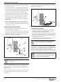
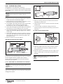
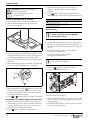
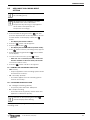
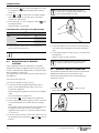
B Turning the plastic #40 Torx screw clockwise.
P2 CO2 levels will increase.
Note: This screw adjustment is very
sensitive and should be made in small
increments. It may take several minutes for
readings to stabilize.
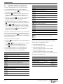
Program
CO2 values measured
P1
______________ %
P2
______________ %
Date
Tab. 19
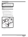
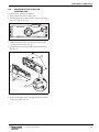
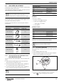
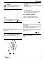
Reassemble all parts in reverse order:
B Return slotted screw cover to original position and
tighten the philips screw (Æ Fig. 58).
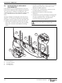
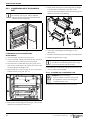
B Reinstall Torx protection cover (Æ Fig. 59).
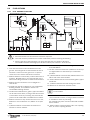
B Remove CO2 analyzer probe and reinstall flathead
screw with gasket in exhaust collar.
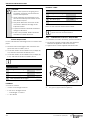
B Press ON/OFF button to turn OFF the heater.
B Press ON/OFF button to turn ON the heater.
Heater is ready for normal operation.
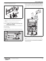
Fig. 59 Adjusting P2 CO2 level
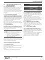
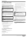
B Verify both P1 and P2 CO2 readings are within the
ranges specified in table 18.
B Repeat steps 1 and 2 as necesssary until CO2 values
are within the specified ranges.
As soon as the levels of CO2 are correct, verify the
values of CO corresponds to the limits of the table 18.
If the values exceed the limits, it is necessary to verify
the ventilation system and heat exchanger.
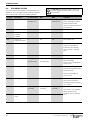
CO2 range (%)
Max. CO level
(measured)
Natural gas
Max.
P1
8.1% - 8.9%
< 200 ppm
Min.
P2
2.0% - 2.6%
< 30 ppm
Max.
P1
9.2% - 10%
< 250 ppm
Min.
P2
2.0% - 2.6%
< 30 ppm
Propane
Note: Values above are for controlled climate
conditions.
Inputs such as gas pressure, heating value of the gas,
humidity and temperature of combustion air impact
CO and CO2 values. Changes in these inputs can
result in different CO and CO2 values on the same
appliance.
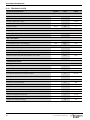
Tab. 18 CO2 & CO target numbers
END OF ADJUSTMENTS
B Record the final values in table 19.
6 720 646 322 (2012/05)
39