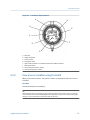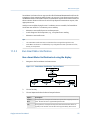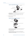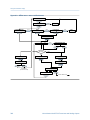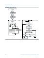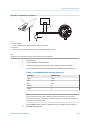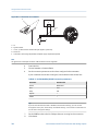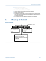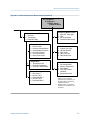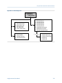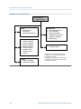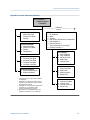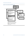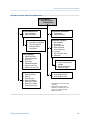
1
Configuration and Use Manual
MMI-20019043, Rev AA
March 2012
Micro Motion® Model 2700 Transmitters with
Analog Outputs
Configuration and Use Manual
Safety messages
Safety messages are provided throughout this manual to protect personnel and equipment. Read each safety message carefully
before proceeding to the next step.
Micro Motion customer service
Location
Telephone number
Email
U.S.A.
800-522-MASS (800-522-6277) (toll free)
[email protected]
Canada and Latin America
+1 303-527-5200 (U.S.A.)
Asia
Japan
3 5769-6803
All other locations
+65 6777-8211 (Singapore)
U.K.
0870 240 1978 (toll-free)
All other locations
+31 (0) 318 495 555 (The Netherlands)
Europe
Contents
Contents
Part I Getting Started
Chapter 1
Before you begin .............................................................................................................3
1.1
1.2
1.3
1.4
Chapter 2
About this manual .........................................................................................................................3
Transmitter model code ................................................................................................................3
Communications tools and protocols ............................................................................................3
Additional documentation and resources ......................................................................................4
Quick start .......................................................................................................................7
2.1
2.2
2.3
2.4
2.5
2.6
Power up the transmitter ...............................................................................................................7
Check flowmeter status .................................................................................................................7
Make a startup connection to the transmitter ................................................................................9
Characterize the flowmeter (if required) ......................................................................................10
2.4.1
Sources and formats for characterization parameters ...................................................10
Verify mass flow measurement ....................................................................................................13
Verify the zero .............................................................................................................................14
2.6.1
Verify the zero using ProLink II ......................................................................................14
2.6.2
Verify the zero using ProLink III .....................................................................................15
2.6.3
Terminology used with zero verification and zero calibration ........................................16
Part II Configuration and commissioning
Chapter 3
Introduction to configuration and commissioning .........................................................19
3.1
3.2
3.3
3.4
3.5
Chapter 4
Configuration flowchart ..............................................................................................................19
Default values and ranges ............................................................................................................21
Enable access to the off-line menu of the display .........................................................................21
Disable write-protection on the transmitter configuration ..........................................................21
Restore the factory configuration ................................................................................................22
Configure process measurement ...................................................................................23
4.1
4.2
4.3
4.4
Configure mass flow measurement .............................................................................................23
4.1.1
Configure Mass Flow Measurement Unit .......................................................................23
4.1.2
Configure Flow Damping ..............................................................................................26
4.1.3
Configure Mass Flow Cutoff ..........................................................................................27
Configure volume flow measurement for liquid applications .......................................................29
4.2.1
Configure Volume Flow Type for liquid applications ......................................................29
4.2.2
Configure Volume Flow Measurement Unit for liquid applications ................................30
4.2.3
Configure Volume Flow Cutoff ......................................................................................33
Configure gas standard volume (GSV) flow measurement ...........................................................34
4.3.1
Configure Volume Flow Type for gas applications .........................................................35
4.3.2
Configure Standard Gas Density ....................................................................................35
4.3.3
Configure Gas Standard Volume Flow Measurement Unit .............................................36
4.3.4
Configure Gas Standard Volume Flow Cutoff ................................................................39
Configure Flow Direction .............................................................................................................40
4.4.1
Options for Flow Direction ............................................................................................41
Configuration and Use Manual
i
Contents
4.5
4.6
4.7
4.8
4.9
Chapter 5
Configure device options and preferences .....................................................................77
5.1
5.2
5.3
5.4
5.5
5.6
ii
Configure density measurement ................................................................................................. 45
4.5.1
Configure Density Measurement Unit ...........................................................................46
4.5.2
Configure slug flow parameters ....................................................................................47
4.5.3
Configure Density Damping ..........................................................................................48
4.5.4
Configure Density Cutoff .............................................................................................. 50
Configure temperature measurement .........................................................................................50
4.6.1
Configure Temperature Measurement Unit .................................................................. 51
4.6.2
Configure Temperature Damping .................................................................................51
Configure the petroleum measurement application ....................................................................53
4.7.1
Configure petroleum measurement using ProLink II ..................................................... 53
4.7.2
Configure petroleum measurement using ProLink III .................................................... 54
4.7.3
Configure petroleum measurement using the Field Communicator ..............................56
4.7.4
API reference tables ......................................................................................................57
Configure the concentration measurement application .............................................................. 58
4.8.1
Configure concentration measurement using ProLink II ................................................58
4.8.2
Configure concentration measurement using ProLink III ...............................................61
4.8.3
Configure concentration measurement using the Field Communicator ........................64
4.8.4
Standard matrices for the concentration measurement application ..............................66
4.8.5
Derived variables and calculated process variables ........................................................67
Configure pressure compensation ...............................................................................................69
4.9.1
Configure pressure compensation using ProLink II ........................................................69
4.9.2
Configure pressure compensation using ProLink III .......................................................71
4.9.3
Configure pressure compensation using the Field Communicator ................................ 73
4.9.4
Options for Pressure Measurement Unit ....................................................................... 74
Configure the transmitter display ................................................................................................77
5.1.1
Configure the language used for the display ................................................................. 77
5.1.2
Configure the process variables shown on the display ...................................................78
5.1.3
Configure the precision of variables shown on the display .............................................79
5.1.4
Configure the refresh rate of data shown on the display ................................................80
5.1.5
Enable or disable automatic scrolling through the display variables .............................. 81
5.1.6
Enable or disable the display backlight ..........................................................................81
5.1.7
Enable or disable Status LED Blinking ............................................................................ 82
Enable or disable operator actions from the display .....................................................................82
5.2.1
Enable or disable Totalizer Start/Stop from the display ..................................................83
5.2.2
Enable or disable Totalizer Reset from the display .........................................................83
5.2.3
Enable or disable the Acknowledge All Alarms display command ..................................84
Configure security for the display menus ....................................................................................85
Configure response time parameters .......................................................................................... 86
5.4.1
Configure Update Rate ................................................................................................. 87
5.4.2
Configure Calculation Speed (Response Time) ..............................................................89
Configure alarm handling ............................................................................................................89
5.5.1
Configure Fault Timeout ...............................................................................................90
5.5.2
Configure Status Alarm Severity ....................................................................................90
Configure informational parameters ........................................................................................... 94
5.6.1
Configure Descriptor .................................................................................................... 95
5.6.2
Configure Message .......................................................................................................95
5.6.3
Configure Date ............................................................................................................. 96
5.6.4
Configure Sensor Serial Number ................................................................................... 96
5.6.5
Configure Sensor Material .............................................................................................97
Micro Motion® Model 2700 Transmitters with Analog Outputs
Contents
5.6.6
5.6.7
Chapter 6
Integrate the meter with the control system ..................................................................99
6.1
6.2
6.3
6.4
6.5
6.6
Chapter 7
Configure the transmitter channels .............................................................................................99
Configure the mA output ..........................................................................................................100
6.2.1
Configure mA Output Process Variable .......................................................................100
6.2.2
Configure Lower Range Value (LRV) and Upper Range Value (URV) .............................102
6.2.3
Configure AO Cutoff ...................................................................................................104
6.2.4
Configure Added Damping .........................................................................................105
6.2.5
Configure mA Output Fault Action and mA Output Fault Level ....................................107
Configure the frequency output ................................................................................................108
6.3.1
Configure Frequency Output Process Variable ............................................................108
6.3.2
Configure Frequency Output Polarity ..........................................................................110
6.3.3
Configure Frequency Output Scaling Method .............................................................111
6.3.4
Configure Frequency Output Maximum Pulse Width ..................................................112
6.3.5
Configure Frequency Output Fault Action and Frequency Output Fault Level ..............113
Configure the discrete output ...................................................................................................114
6.4.1
Configure Discrete Output Source ..............................................................................115
6.4.2
Configure Discrete Output Polarity .............................................................................118
6.4.3
Configure Discrete Output Fault Action ......................................................................119
Configure events .......................................................................................................................120
6.5.1
Configure a basic event ...............................................................................................121
6.5.2
Configure an enhanced event .....................................................................................121
Configure digital communications ............................................................................................124
6.6.1
Configure HART/Bell 202 communications .................................................................124
6.6.2
Configure HART/RS-485 communications ..................................................................129
6.6.3
Configure Modbus/RS-485 communications ..............................................................130
6.6.4
Configure Digital Communications Fault Action .........................................................131
Completing the configuration ......................................................................................135
7.1
7.2
7.3
Chapter 8
Configure Sensor Liner Material .................................................................................... 97
Configure Sensor Flange Type .......................................................................................98
Test or tune the system using sensor simulation ........................................................................135
7.1.1
Sensor simulation .......................................................................................................136
Back up transmitter configuration .............................................................................................137
Enable write-protection on the transmitter configuration .........................................................138
Set up the Weights & Measures application .................................................................139
8.1
8.2
8.3
Weights & Measures application ................................................................................................139
Set up the Weights & Measures application using ProLink II .......................................................140
Set up the Weights & Measures application using ProLink III ......................................................143
Part III Operations, maintenance, and troubleshooting
Chapter 9
Transmitter operation .................................................................................................149
9.1
9.2
9.3
9.4
Record the process variables .....................................................................................................149
View process variables ...............................................................................................................150
9.2.1
View process variables using the display .....................................................................150
9.2.2
View process variables using ProLink III .......................................................................151
View transmitter status using the status LED .............................................................................152
View and acknowledge status alarms ........................................................................................152
9.4.1
View and acknowledge alarms using the display .........................................................152
9.4.2
View and acknowledge alarms using ProLink II ............................................................155
Configuration and Use Manual
iii
Contents
9.5
9.6
9.7
9.8
Chapter 10
Operate the transmitter with the Weights & Measures application ..............................163
10.1
10.2
10.3
10.4
Chapter 11
11.3
11.4
11.5
11.6
11.7
Options for measurement support ............................................................................................173
Use Smart Meter Verification .....................................................................................................173
11.2.1 Smart Meter Verification requirements .......................................................................174
11.2.2 Smart Meter Verification test preparation ...................................................................174
11.2.3 Run Smart Meter Verification ......................................................................................175
11.2.4 View test data .............................................................................................................179
11.2.5 Schedule automatic execution of the Smart Meter Verification test ............................183
Zero the flowmeter ...................................................................................................................186
11.3.1 Zero the flowmeter using the display ..........................................................................187
11.3.2 Zero the flowmeter using ProLink II .............................................................................188
11.3.3 Zero the flowmeter using ProLink III ............................................................................189
11.3.4 Zero the flowmeter using the Field Communicator .....................................................191
Validate the meter .....................................................................................................................192
11.4.1 Alternate method for calculating the meter factor for volume flow .............................193
Perform a (standard) D1 and D2 density calibration ...................................................................194
11.5.1 Perform a D1 and D2 density calibration using ProLink II .............................................194
11.5.2 Perform a D1 and D2 density calibration using ProLink III ............................................196
11.5.3 Perform a D1 and D2 density calibration using the Field Communicator .....................197
Perform a D3 and D4 density calibration (T-Series sensors only) ................................................199
11.6.1 Perform a D3 or D3 and D4 density calibration using ProLink II ....................................199
11.6.2 Perform a D3 or D3 and D4 density calibration using ProLink III ...................................200
11.6.3 Perform a D3 or D3 and D4 density calibration using the Field Communicator ............201
Perform temperature calibration ...............................................................................................203
Troubleshooting ..........................................................................................................207
12.1
12.2
iv
Operate the transmitter when the Weights & Measures application is installed .........................163
10.1.1 Approved methods to read or obtain process data ......................................................164
10.1.2 Large totalizer values on the display (OIML applications only) .....................................164
10.1.3 Effect of the Weights & Measures application on process measurement and
outputs .......................................................................................................................165
10.1.4 Effect of the Weights & Measures application on operation and maintenance
functions ....................................................................................................................166
Switch between secured and unsecured mode ..........................................................................168
10.2.1 Switch between secured and unsecured mode using ProLink II ...................................169
10.2.2 Switch between secured and unsecured mode using ProLink III ..................................169
10.2.3 Switch between secured and unsecured mode using the switching utility ...................170
Clear Status Alarm A027: Security Breach ..................................................................................170
Replacing the core processor in a Weights & Measures installation ............................................171
Measurement support .................................................................................................173
11.1
11.2
Chapter 12
9.4.3
View and acknowledge alerts using ProLink III .............................................................156
9.4.4
View alarms using the Field Communicator ................................................................156
9.4.5
Alarm data in transmitter memory ..............................................................................157
Read totalizer and inventory values ...........................................................................................157
Start and stop totalizers and inventories ....................................................................................158
9.6.1
Start and stop totalizers and inventories using the display ..........................................158
Reset totalizers ..........................................................................................................................160
9.7.1
Reset totalizers using the display ................................................................................160
Reset inventories .......................................................................................................................161
Status LED states .......................................................................................................................208
Status alarms .............................................................................................................................208
Micro Motion® Model 2700 Transmitters with Analog Outputs
Contents
12.3
12.4
12.5
12.6
12.7
12.8
12.9
12.10
12.11
12.12
12.13
12.14
12.15
12.16
12.17
12.18
12.19
12.20
12.21
12.22
12.23
12.24
12.25
12.26
12.27
12.28
12.29
12.30
Flow measurement problems ....................................................................................................220
Density measurement problems ...............................................................................................222
Temperature measurement problems .......................................................................................223
Milliamp output problems .........................................................................................................224
Frequency output problems ......................................................................................................225
Use sensor simulation for troubleshooting ................................................................................226
Check power supply wiring ........................................................................................................227
Check sensor-to-transmitter wiring ...........................................................................................227
Check grounding .......................................................................................................................228
Perform loop tests .....................................................................................................................228
12.12.1 Perform loop tests using the display ...........................................................................228
12.12.2 Perform loop tests using ProLink II ..............................................................................230
12.12.3 Perform loop tests using ProLink III .............................................................................231
12.12.4 Perform loop tests using the Field Communicator ......................................................233
Check for radio frequency interference (RFI) ..............................................................................234
Check the HART communication loop .......................................................................................235
Check HART Address and Loop Current Mode ............................................................................235
Check HART burst mode ............................................................................................................236
Check the trimming of the mA output .......................................................................................236
Check Lower Range Value and Upper Range Value ....................................................................236
Check mA Output Fault Action ..................................................................................................236
Check Frequency Output Maximum Pulse Width .......................................................................237
Check Frequency Output Scaling Method ..................................................................................237
Check Frequency Output Fault Action .......................................................................................237
Check Flow Direction .................................................................................................................237
Check the cutoffs ......................................................................................................................238
Check for slug flow (two-phase flow) .........................................................................................238
Check the drive gain ..................................................................................................................239
12.26.1 Collect drive gain data ................................................................................................240
Check the pickoff voltage ..........................................................................................................240
12.27.1 Collect pickoff voltage data ........................................................................................241
Check for electrical shorts ..........................................................................................................241
12.28.1 Check the sensor coils .................................................................................................242
Check the core processor LED ....................................................................................................243
12.29.1 Core processor LED states ...........................................................................................246
Perform a core processor resistance test ...................................................................................247
Appendices and reference
Appendix A Using the transmitter display .......................................................................................251
A.1
A.2
A.3
A.4
A.5
A.6
Components of the transmitter interface ..................................................................................251
Use the optical switches ............................................................................................................252
Access and use the display menu system ...................................................................................253
A.3.1
Enter a floating-point value using the display ..............................................................254
Display codes for process variables ............................................................................................257
Codes and abbreviations used in display menus ........................................................................259
Menu maps for the transmitter display ......................................................................................262
Appendix B Using ProLink II with the transmitter ...........................................................................273
B.1
B.2
Basic information about ProLink II ..............................................................................................273
Connect with ProLink II ..............................................................................................................274
B.2.1
ProLink II connection types .........................................................................................274
Configuration and Use Manual
v
Contents
B.3
B.2.2
Make a service port connection ...................................................................................275
B.2.3
Make a HART/Bell 202 connection ..............................................................................276
B.2.4
Make a HART/RS-485 connection ................................................................................281
B.2.5
Make a Modbus/RS-485 connection ............................................................................284
Menu maps for ProLink II ...........................................................................................................287
Appendix C Using ProLink III with the transmitter ...........................................................................297
C.1
C.2
C.3
Basic information about ProLink III .............................................................................................297
Connect with ProLink III .............................................................................................................298
C.2.1
ProLink III connection types ........................................................................................298
C.2.2
Make a service port connection ...................................................................................299
C.2.3
Make a HART/Bell 202 connection ..............................................................................300
C.2.4
Make a HART/RS-485 connection ................................................................................305
C.2.5
Make a Modbus/RS-485 connection ............................................................................308
Menu maps for ProLink III ..........................................................................................................311
Appendix D Using the Field Communicator with the transmitter .....................................................321
D.1
D.2
D.3
Basic information about the Field Communicator ......................................................................321
Connect with the Field Communicator ......................................................................................322
Menu maps for the Field Communicator ....................................................................................324
Appendix E Default values and ranges ............................................................................................341
E.1
Default values and ranges ..........................................................................................................341
Appendix F Transmitter components and installation wiring .........................................................347
F.1
F.2
F.3
Installation types .......................................................................................................................347
Power supply terminals and ground ...........................................................................................351
Input/output (I/O) wiring terminals ...........................................................................................352
Appendix G NE 53 history ...............................................................................................................353
G.1
NE 53 history .............................................................................................................................353
Index ................................................................................................................................................357
vi
Micro Motion® Model 2700 Transmitters with Analog Outputs
Getting Started
Part I
Getting Started
Chapters covered in this part:
•
Before you begin
•
Quick start
Configuration and Use Manual
1
Getting Started
2
Micro Motion® Model 2700 Transmitters with Analog Outputs
Before you begin
1
Before you begin
Topics covered in this chapter:
•
•
•
•
1.1
About this manual
Transmitter model code
Communications tools and protocols
Additional documentation and resources
About this manual
This manual provides information to help you configure, commission, use, maintain, and
troubleshoot the Micro Motion Model 2700 transmitter.
Important
This manual assumes that the transmitter has been installed correctly and completely, according to
the instructions in the transmitter installation manual, and that the installation complies with all
applicable safety requirements.
1.2
Transmitter model code
Your transmitter can be identified by the model number on the transmitter tag.
The transmitter has a model number of the following form:
2700(I/R/C/B)**A******
1.3
I
Integral mount
R
4-wire remote-mount
C
9-wire remote-mount
B
Remote core processor with remote transmitter
A
Analog outputs option board
Communications tools and protocols
You can use several different communications tools and protocols to interface with the
transmitter. You may use different tools in different locations or for different tasks.
Configuration and Use Manual
3
Before you begin
Table 1-1: Communications tools, protocols, and related information
Communications tool
Supported protocols
Scope
In this manual
Display
Not applicable
Basic configuration and
commissioning
Complete user informa- Not applicable
tion. See Appendix A.
ProLink II
•
•
•
•
HART/RS-485
HART/Bell 202
Modbus/RS-485
Service port
Complete configuration Basic user information.
and commissioning
See Appendix B.
User manual
• Installed with software
• On Micro Motion
user documentation
CD
• On Micro Motion
web site (www.micromotion.com
ProLink III
•
•
•
•
HART/RS-485
HART/Bell 202
Modbus/RS-485
Service port
Complete configuration Basic user information.
and commissioning
See Appendix C.
User manual
• Installed with software
• On Micro Motion
user documentation
CD
• On Micro Motion
web site (www.micromotion.com
Field Communicator
HART/Bell 202
Complete configuration Basic user information.
and commissioning
See Appendix D.
User manual on
Micro Motion web site
(www.micromotion.com
For more information
Tip
You may be able to use other communications tools from Emerson Process Management, such as
AMS Suite: Intelligent Device Manager, or the Smart Wireless THUM™ Adapter. Use of AMS or the
Smart Wireless THUM Adapter is not discussed in this manual. The AMS interface is similar to the
ProLink II interface. For more information on the Smart Wireless THUM Adapter, refer to the
documentation available at www.micromotion.com.
1.4
Additional documentation and resources
Micro Motion provides additional documentation to support the installation and operation
of the transmitter.
Table 1-2: Additional documentation and resources
4
Topic
Document
Sensor
Sensor documentation
Micro Motion® Model 2700 Transmitters with Analog Outputs
Before you begin
Table 1-2: Additional documentation and resources (continued)
Topic
Document
Transmitter installation
Micro Motion Model 1700 and Model 2700 Transmitters: Installation
Manual
Hazardous area installation
See the approval documentation shipped with the transmitter, or
download the appropriate documentation from the Micro Motion
web site at www.micromotion.com.
All documentation resources are available on the Micro Motion web site at
www.micromotion.com or on the Micro Motion user documentation CD.
Configuration and Use Manual
5
Before you begin
6
Micro Motion® Model 2700 Transmitters with Analog Outputs
Quick start
2
Quick start
Topics covered in this chapter:
•
•
•
•
•
•
2.1
Power up the transmitter
Check flowmeter status
Make a startup connection to the transmitter
Characterize the flowmeter (if required)
Verify mass flow measurement
Verify the zero
Power up the transmitter
The transmitter must be powered up for all configuration and commissioning tasks, or for
process measurement.
1.
Ensure that all transmitter and sensor covers and seals are closed.
CAUTION!
To prevent ignition of flammable or combustible atmospheres, ensure that all covers
and seals are tightly closed. For hazardous area installations, applying power while
housing covers are removed or loose can cause an explosion.
2.
Turn on the electrical power at the power supply.
The transmitter will automatically perform diagnostic routines. During this period,
Alarm 009 is active. The diagnostic routines should complete in approximately
30 seconds. For transmitters with a display, the status LED will turn green and begin
to flash when the startup diagnostics are complete. If the status LED exhibits
different behavior, an alarm condition is present.
Postrequisites
Although the sensor is ready to receive process fluid shortly after power-up, the electronics
can take up to 10 minutes to reach thermal equilibrium. Therefore, if this is the initial
startup, or if power is been off long enough to allow components to reach ambient
temperature, allow the electronics to warm up for approximately 10 minutes before
relying on process measurements. During this warm-up period, you may observe minor
measurement instability or inaccuracy.
2.2
Check flowmeter status
Check the flowmeter for any error conditions that require user action or that affect
measurement accuracy.
Configuration and Use Manual
7
Quick start
1.
Wait approximately 10 seconds for the power-up sequence to complete.
Immediately after power-up, the transmitter runs through diagnostic routines and
checks for error conditions. During the power-up sequence, Alarm A009 is active.
This alarm should clear automatically when the power-up sequence is complete.
2.
Check the status LED on the transmitter.
Table 2-1: Transmitter status reported by status LED
LED state
Description
Recommendation
Green
No alarms are active.
Continue with configuration or process measurement.
Flashing green(1)
No alarms are active. One or more previously
active alarms have not been acknowledged.
Continue with configuration or process measurement. If you choose, you can acknowledge
the alarms.
Yellow
One or more low-severity alarms are active,
and have been acknowledged.
A low-severity alarm condition does not affect
measurement accuracy or output behavior.
You can continue with configuration or process measurement. If you choose, you can identify and resolve the alarm condition.
Flashing yellow(2)
One or more low-severity alarms are active
and have not been acknowledged.
A low-severity alarm condition does not affect
measurement accuracy or output behavior.
You can continue with configuration or process measurement. If you choose, you can identify and resolve the alarm condition. You may
also acknowledge the alarm.
Red
One or more high-severity alarms are active,
and have been acknowledged.
A high-severity alarm condition affects measurement accuracy and output behavior. Resolve the alarm condition before continuing.
Flashing red(3)
One or more high-severity alarms are active
and have not been acknowledged.
A high-severity alarm condition affects measurement accuracy and output behavior. Resolve the alarm condition before continuing.
You may also acknowledge the alarm.
Postrequisites
For information on viewing the list of active alarms, see Section 9.4.
For information on individual alarms and suggested resolutions, see Section 12.2.
(1) If Status LED Blinking is disabled, the LED will show solid green rather than flashing.
(2) If Status LED Blinking is disabled, the LED will show solid yellow rather than flashing.
(3) If Status LED Blinking is disabled, the LED will show solid red rather than flashing.
8
Micro Motion® Model 2700 Transmitters with Analog Outputs
Quick start
2.3
Make a startup connection to the transmitter
For all configuration tools except the display, you must have an active connection to the
transmitter to configure the transmitter. Follow this procedure to make your first
connection to the transmitter.
Identify the connection type to use, and follow the instructions for that connection type in
the appropriate appendix. Use the default communications parameters shown in the
appendix.
Communications tool
Connection type to use
Instructions
ProLink II
HART/RS-485
Appendix B
ProLink III
HART/RS-485
Appendix C
Field Communicator
HART
Appendix D
Postrequisites
(Optional) Change the communications parameters to site-specific values.
To change the communications parameters using ProLink II:
•
To change the protocol, baud rate, parity, or stop bits, choose ProLink > Configuration >
RS-485.
•
To change the address, choose ProLink > Configuration > Device.
To change the communications parameters using ProLink III, choose Device Tools >
Configuration > Communications.
To change the communications parameters using the Field Communicator, choose On-Line
Menu > Configure > Manual Setup > Inputs/Outputs > Communications.
Important
If you are changing communications parameters for the connection type that you are using, you will
lose the connection when you write the parameters to the transmitter. Reconnect using the new
parameters.
Configuration and Use Manual
9
Quick start
2.4
Characterize the flowmeter (if required)
Display
Not available
ProLink II
•
ProLink > Configuration > Device > Sensor Type
•
ProLink > Configuration > Flow
•
ProLink > Configuration > Density
•
ProLink > Configuration > T Series
ProLink III
Device Tools > Calibration Data
Field Communicator Configure > Manual Setup > Characterize
Overview
Characterizing the flowmeter adjusts your transmitter to match the unique traits of the
sensor it is paired with. The characterization parameters (also called calibration
parameters) describe the sensor’s sensitivity to flow, density, and temperature.
Depending on your sensor type, different parameters are required. Values for your sensor
are provided by Micro Motion on the sensor tag or the calibration certificate.
Tip
If your flowmeter was ordered as a unit, it has already been characterized at the factory. However,
you should still verify the characterization parameters.
Procedure
1.
Specify Sensor Type.
• Straight-tube (T-Series)
• Curved-tube (all sensors except T-Series)
2.
Set the flow characterization parameters. Be sure to include all decimal points.
• For straight-tube sensors, set FCF (Flow Cal or Flow Calibration Factor), FTG, and FFQ.
• For curved-tube sensors, set Flow Cal (Flow Calibration Factor).
3.
Set the density characterization parameters.
• For straight-tube sensors, set D1, D2, DT, DTG, K1, K2, FD, DFQ1, and DFQ2.
• For curved-tube sensors, set D1, D2, TC, K1, K2, and FD. (TC is sometimes shown
as DT.)
2.4.1
Sources and formats for characterization parameters
Different sensor tags display characterization parameters differently. On older sensors, the
sensor tag may not contain all the required parameters.
Sample sensor tags
Sample sensor tags are shown in the following illustrations:
10
Micro Motion® Model 2700 Transmitters with Analog Outputs
Quick start
•
Older curved-tube sensors (all sensors except T-Series): see Figure 2-1
•
Newer curved-tube sensors (all sensors except T-Series): see Figure 2-2
•
Older straight-tube sensors (T-Series): see Figure 2-3
•
Newer straight-tube sensors (T-Series): see Figure 2-4
Figure 2-1: Tag on older curved-tube sensors (all sensors except T-Series)
Figure 2-2: Tag on newer curved-tube sensors (all sensors except T-Series)
Configuration and Use Manual
11
Quick start
Figure 2-3: Tag on older straight-tube sensor (T-Series)
Figure 2-4: Tag on newer straight-tube sensor (T-Series)
Density calibration parameters (D1, D2, K1, K2, FD, DT, TC)
If your sensor tag does not show a D1 or D2 value:
•
For D1, enter the Dens A or D1 value from the calibration certificate. This value is the
line-condition density of the low-density calibration fluid. Micro Motion uses air. If
you cannot find a Dens A or D1 value, enter 0.001 g/cm3.
•
For D2, enter the Dens B or D2 value from the calibration certificate. This value is the
line-condition density of the high-density calibration fluid. Micro Motion uses water.
If you cannot find a Dens B or D2 value, enter 0.998 g/cm3.
If your sensor tag does not show a K1 or K2 value:
•
For K1, enter the first 5 digits of the density calibration factor. In the sample tag, this
value is shown as 12500 (see Figure 2-1).
•
For K2, enter the second 5 digits of the density calibration factor. In the sample tag,
this value is shown as 14286 (see Figure 2-1).
If your sensor does not show an FD value, contact Micro Motion customer service.
12
Micro Motion® Model 2700 Transmitters with Analog Outputs
Quick start
If your sensor tag does not show a DT or TC value, enter the last 3 digits of the density
calibration factor. In the sample tag, this value is shown as 4.44 (see Figure 2-1).
Flow calibration parameters (FCF, FT)
Two separate values are used to describe flow calibration: a 6-character FCF value and a 4character FT value. Both values contain decimal points. During characterization, these may
be entered as two values or as a single 10-character string. The 10-character string is called
either Flowcal or FCF.
If your sensor tag shows the FCF and the FT values separately and you need to enter a
single value, concatenate the two values to form the single parameter value.
If your sensor tag shows a concatenated Flowcal or FCF value and you need to enter the FCF
and the FT values separately, split the concatenated value:
•
FCF = The first 6 characters, including the decimal point
•
FT = The last 4 characters, including the decimal point
Example: Concatenating FCF and FT
FCF = x.xxxx
FT = y.yy
Flow calibration parameter: x.xxxxy.yy
Example: Splitting the concatenated Flowcal or FCF value
Flow calibration parameter: x.xxxxy.yy
FCF = x.xxxx
FT = y.yy
2.5
Verify mass flow measurement
Check to see that the mass flow rate reported by the transmitter is accurate. You can use
any available method.
•
Read the value for Mass Flow Rate on the transmitter display.
•
Connect to the transmitter with ProLink II and read the value for Mass Flow Rate in the
Process Variables window (ProLink > Process Variables).
•
Connect to the transmitter with ProLink III and read the value for Mass Flow Rate in
the Process Variables panel.
•
Connect to the transmitter with the Field Communicator and read the value for Mass
Flow Rate in the Process Variables menu (On-Line Menu > Overview > Primary Purpose
Variables).
Postrequisites
If the reported mass flow rate is not accurate:
•
Check the characterization parameters.
Configuration and Use Manual
13
Quick start
•
2.6
Review the troubleshooting suggestions for flow measurement issues. See
Section 12.3.
Verify the zero
Verifying the zero helps you determine if the stored zero value is appropriate to your
installation, or if a field zero can improve measurement accuracy.
The zero verification procedure analyzes the Live Zero value under conditions of zero flow,
and compares it to the Zero Stability range for the sensor. If the average Live Zero value is
within a reasonable range, the zero value stored in the transmitter is valid. Performing a
field calibration will not improve measurement accuracy.
2.6.1
Verify the zero using ProLink II
Verifying the zero helps you determine if the stored zero value is appropriate to your
installation, or if a field zero can improve measurement accuracy.
Important
In most cases, the factory zero is more accurate than the field zero. Do not zero the flowmeter unless
one of the following is true:
•
The zero is required by site procedures.
•
The stored zero value fails the zero verification procedure.
Prerequisites
ProLink II v2.94 or later
Important
Do not verify the zero or zero the flowmeter if a high-severity alarm is active. Correct the problem,
then verify the zero or zero the flowmeter. You may verify the zero or zero the flowmeter if a lowseverity alarm is active.
Procedure
1.
Prepare the flowmeter:
a. Allow the flowmeter to warm up for at least 20 minutes after applying power.
b. Run the process fluid through the sensor until the sensor temperature reaches
the normal process operating temperature.
c. Stop flow through the sensor by shutting the downstream valve, and then the
upstream valve if available.
d. Verify that the sensor is blocked in, that flow has stopped, and that the sensor is
completely full of process fluid.
2.
14
Choose ProLink > Calibration > Zero Verification and Calibration > Verify Zero and wait until
the procedure completes.
Micro Motion® Model 2700 Transmitters with Analog Outputs
Quick start
3.
If the zero verification procedure fails:
a. Confirm that the sensor is completely blocked in, that flow has stopped, and that
the sensor is completely full of process fluid.
b. Verify that the process fluid is not flashing or condensing, and that it does not
contain particles that can settle out.
c. Repeat the zero verification procedure.
d. If it fails again, zero the flowmeter.
For instructions on zeroing the flowmeter, see Section 11.3.
Postrequisites
Restore normal flow through the sensor by opening the valves.
2.6.2
Verify the zero using ProLink III
Verifying the zero helps you determine if the stored zero value is appropriate to your
installation, or if a field zero can improve measurement accuracy.
Important
In most cases, the factory zero is more accurate than the field zero. Do not zero the flowmeter unless
one of the following is true:
•
The zero is required by site procedures.
•
The stored zero value fails the zero verification procedure.
Prerequisites
ProLink III v1.0 with Patch Build 31, or a later release
Important
Do not verify the zero or zero the flowmeter if a high-severity alarm is active. Correct the problem,
then verify the zero or zero the flowmeter. You may verify the zero or zero the flowmeter if a lowseverity alarm is active.
Procedure
1.
Prepare the flowmeter:
a. Allow the flowmeter to warm up for at least 20 minutes after applying power.
b. Run the process fluid through the sensor until the sensor temperature reaches
the normal process operating temperature.
c. Stop flow through the sensor by shutting the downstream valve, and then the
upstream valve if available.
d. Verify that the sensor is blocked in, that flow has stopped, and that the sensor is
completely full of process fluid.
2.
Choose Device Tools > Device Calibration > Zero Verification and Calibration > Verify Zero and
wait until the procedure completes.
Configuration and Use Manual
15
Quick start
3.
If the zero verification procedure fails:
a. Confirm that the sensor is completely blocked in, that flow has stopped, and that
the sensor is completely full of process fluid.
b. Verify that the process fluid is not flashing or condensing, and that it does not
contain particles that can settle out.
c. Repeat the zero verification procedure.
d. If it fails again, zero the flowmeter.
For instructions on zeroing the flowmeter, see Section 11.3.
Postrequisites
Restore normal flow through the sensor by opening the valves.
2.6.3
Terminology used with zero verification and zero
calibration
Table 2-2: Terminology used with zero verification and zero calibration
Term
Definition
Zero
In general, the offset required to synchronize the left pickoff and the right pickoff under
conditions of zero flow. Unit = microseconds.
Factory Zero
The zero value obtained at the factory, under laboratory conditions.
Field Zero
The zero value obtained by performing a zero calibration outside the factory.
Prior Zero
The zero value stored in the transmitter at the time a field zero calibration is begun. May
be the factory zero or a previous field zero.
Manual Zero
The zero value stored in the transmitter, typically obtained from a zero calibration procedure. It may also be configured manually. Also called “mechanical zero” or “stored zero.”
Live Zero
The real-time bidirectional mass flow rate with no flow damping or mass flow cutoff applied. An adaptive damping value is applied only when the mass flow rate changes dramatically over a very short interval. Unit = configured mass flow measurement unit.
Zero Stability
A laboratory-derived value used to calculate the expected accuracy for a sensor. Under
laboratory conditions at zero flow, the average flow rate is expected to fall within the
range defined by the Zero Stability value (0 ± Zero Stability). Each sensor size and model
has a unique Zero Stability value. Statistically, 95% of all data points should fall within the
range defined by the Zero Stability value.
Zero Calibration
The procedure used to determine the zero value.
Zero Time
The time period over which the Zero Calibration procedure is performed. Unit = seconds.
Field Verification Zero
A 3-minute running average of the Live Zero value, calculated by the transmitter. Unit =
configured mass flow measurement unit.
Zero Verification
A procedure used to evaluate the stored zero and determine whether or not a field zero
can improve measurement accuracy.
16
Micro Motion® Model 2700 Transmitters with Analog Outputs
Configuration and commissioning
Part II
Configuration and commissioning
Chapters covered in this part:
•
Introduction to configuration and commissioning
•
•
•
•
•
Configure process measurement
Configure device options and preferences
Integrate the meter with the control system
Completing the configuration
Set up the Weights & Measures application
Configuration and Use Manual
17
Configuration and commissioning
18
Micro Motion® Model 2700 Transmitters with Analog Outputs
Introduction to configuration and commissioning
3
Introduction to configuration and
commissioning
Topics covered in this chapter:
•
•
•
•
•
3.1
Configuration flowchart
Default values and ranges
Enable access to the off-line menu of the display
Disable write-protection on the transmitter configuration
Restore the factory configuration
Configuration flowchart
Use the following flowchart as a general guide to the configuration and commissioning
process.
Some options may not apply to your installation. Detailed information is provided in the
remainder of this manual. If you are using the Weights & Measures application, additional
configuration and setup are required.
Configuration and Use Manual
19
Introduction to configuration and commissioning
Figure 3-1: Configuration flowchart
Configure process measurement
Configure mass flow
measurement
Configure volume flow
meaurement
Volume flow type
Gas
Liquid
Configure device options and
preferences
Test and move to production
Configure display
parameters
Test or tune transmitter
using sensor simulation
Configure fault handling
parameters
Back up transmitter
configuration
Configure sensor
parameters
Enable write-protection on
transmitter configuration
Define gas properties
Configure device
parameters
Done
Configure flow direction
Integrate device with control system
Configure density
measurement
Configure temperature
measurement
Configure petroleum
measurement (API)
application (if available)
Configure concentration
measurement application
(if available)
Configure the channel(s)
Configure the mA
output(s)
Configure the frequency
output(s)
Configure the discrete
output(s)
Configure events
Configure pressure
compensation (optional)
Configure digital
communications
20
Micro Motion® Model 2700 Transmitters with Analog Outputs
Introduction to configuration and commissioning
3.2
Default values and ranges
See Section E.1 to view the default values and ranges for the most commonly used
parameters.
3.3
Enable access to the off-line menu of the
display
Display
OFF-LINE MAINT > OFF-LINE CONFG > DISPLAY
ProLink II
ProLink > Configuration > Display > Display Options
ProLink III
Device Tools > Configuration > Transmitter Display > Display Security
Field Communicator Configure > Manual Setup > Display > Offline Variable Menu Features
Overview
By default, access to the off-line menu of the display is enabled. If it is disabled, you must
enable it if you want to use the display to configure the transmitter.
Restriction
You cannot use the display to enable access to the off-line menu. You must make a connection from
another tool.
3.4
Disable write-protection on the transmitter
configuration
Display
OFF-LINE MAINT > CONFG > LOCK
ProLink II
ProLink > Configuration > Device > Enable Write Protection
ProLink III
Device Tools > Configuration > Write-Protection
Field Communicator Configure > Manual Setup > Info Parameters > Transmitter Info > Write Protect
Overview
If the transmitter is write-protected, the configuration is locked and you must unlock it
before you can change any configuration parameters. By default, the transmitter is not
write-protected.
Configuration and Use Manual
21
Introduction to configuration and commissioning
Tip
Write-protecting the transmitter prevents accidental changes to configuration. It does not prevent
normal operational use. You can always disable write-protection, perform any required configuration
changes, then re-enable write-protection.
3.5
Restore the factory configuration
Display
Not available
ProLink II
ProLink > Configuration > Device > Restore Factory Configuration
ProLink III
Device Tools > Configuration Transfer > Restore Factory Configuration
Field Communicator Not available
Overview
Restoring the factory configuration returns the transmitter to a known operational
configuration. This may be useful if you experience problems during configuration.
Tip
Restoring the factory configuration is not a common action. You may want to contact Micro Motion
to see if there is a preferred method to resolve any issues.
22
Micro Motion® Model 2700 Transmitters with Analog Outputs
Configure process measurement
4
Configure process measurement
Topics covered in this chapter:
•
•
•
•
•
•
•
•
•
4.1
Configure mass flow measurement
Configure volume flow measurement for liquid applications
Configure gas standard volume (GSV) flow measurement
Configure Flow Direction
Configure density measurement
Configure temperature measurement
Configure the petroleum measurement application
Configure the concentration measurement application
Configure pressure compensation
Configure mass flow measurement
The mass flow measurement parameters control how mass flow is measured and reported.
The mass flow measurement parameters include:
4.1.1
•
Mass Flow Measurement Unit
•
Flow Damping
•
Mass Flow Cutoff
Configure Mass Flow Measurement Unit
Display
OFF-LINE MAINT > OFF-LINE CONFG > UNITS > MASS
ProLink II
ProLink > Configuration > Flow > Mass Flow Units
ProLink III
Device Tools > Configuration > Process Measurement > Flow
Field Communicator Configure > Manual Setup > Measurements > Flow > Mass Flow Unit
Overview
Mass Flow Measurement Unit specifies the unit of measure that will be used for the mass flow
rate. The unit used for mass total and mass inventory is derived from this unit.
Procedure
Set Mass Flow Measurement Unit to the unit you want to use.
The default setting for Mass Flow Measurement Unit is g/sec (grams per second).
Configuration and Use Manual
23
Configure process measurement
Tip
If the measurement unit you want to use is not available, you can define a special measurement unit.
Options for Mass Flow Measurement Unit
The transmitter provides a standard set of measurement units for Mass Flow Measurement
Unit, plus one user-defined special measurement unit. Different communications tools may
use different labels for the units.
Table 4-1: Options for Mass Flow Measurement Unit
Label
Unit description
Display
ProLink II
ProLink III
Field Communicator
Grams per second
G/S
g/sec
g/sec
g/s
Grams per minute
G/MIN
g/min
g/min
g/min
Grams per hour
G/H
g/hr
g/hr
g/h
Kilograms per second
KG/S
kg/sec
kg/sec
kg/s
Kilograms per minute
KG/MIN
kg/min
kg/min
kg/min
Kilograms per hour
KG/H
kg/hr
kg/hr
kg/h
Kilograms per day
KG/D
kg/day
kg/day
kg/d
Metric tons per minute
T/MIN
mTon/min
mTon/min
MetTon/min
Metric tons per hour
T/H
mTon/hr
mTon/hr
MetTon/h
Metric tons per day
T/D
mTon/day
mTon/day
MetTon/d
Pounds per second
LB/S
lbs/sec
lbs/sec
lb/s
Pounds per minute
LB/MIN
lbs/min
lbs/min
lb/min
Pounds per hour
LB/H
lbs/hr
lbs/hr
lb/h
Pounds per day
LB/D
lbs/day
lbs/day
lb/d
Short tons (2000 pounds) per
minute
ST/MIN
sTon/min
sTon/min
STon/min
Short tons (2000 pounds) per
hour
ST/H
sTon/hr
sTon/hr
STon/h
Short tons (2000 pounds) per
day
ST/D
sTon/day
sTon/day
STon/d
Long tons (2240 pounds) per
hour
LT/H
lTon/hr
lTon/hr
LTon/h
Long tons (2240 pounds) per
day
LT/D
lTon/day
lTon/day
LTon/d
Special unit
SPECL
special
special
Spcl
24
Micro Motion® Model 2700 Transmitters with Analog Outputs
Configure process measurement
Define a special measurement unit for mass flow
Display
Not available
ProLink II
ProLink > Configuration > Special Units
ProLink III
Device Tools > Configuration > Process Measurement > Flow > Special Units
Field Communicator Configure > Manual Setup > Measurements > Special Units > Mass Special Units
Overview
A special measurement unit is a user-defined unit of measure that allows you to report
process data, totalizer data, and inventory data in a unit that is not available in the
transmitter. A special measurement unit is calculated from an existing measurement unit
using a conversion factor.
Note
Although you cannot define a special measurement unit using the display, you can use the display to
select an existing special measurement unit, and to view process data using the special
measurement unit.
Procedure
1.
Specify Base Mass Unit.
Base Mass Unit is the existing mass unit that the special unit will be based on.
2.
Specify Base Time Unit.
Base Time Unit is the existing time unit that the special unit will be based on.
3.
Calculate Mass Flow Conversion Factor as follows:
a. x base units = y special units
b. Mass Flow Conversion Factor = x/y
4.
Enter Mass Flow Conversion Factor.
5.
Set Mass Flow Label to the name you want to use for the mass flow unit.
6.
Set Mass Total Label to the name you want to use for the mass total and mass
inventory unit.
The special measurement unit is stored in the transmitter. You can configure the
transmitter to use the special measurement unit at any time.
Example: Defining a special measurement unit for mass flow
You want to measure mass flow in ounces per second (oz/sec).
1.
Set Base Mass Unit to Pounds (lb).
2.
Set Base Time Unit to Seconds (sec).
3.
Calculate Mass Flow Conversion Factor:
Configuration and Use Manual
25
Configure process measurement
a. 1 lb/sec = 16 oz/sec
b. Mass Flow Conversion Factor = 1/16 = 0.0625
4.1.2
4.
Set Mass Flow Conversion Factor to 0.0625.
5.
Set Mass Flow Label to oz/sec.
6.
Set Mass Total Label to oz.
Configure Flow Damping
Display
Not available
ProLink II
ProLink > Configuration > Flow > Flow Damp
ProLink III
Device Tools > Configuration > Process Measurement > Flow
Field Communicator Configure > Manual Setup > Measurements > Flow > Flow Damping
Overview
Damping is used to smooth out small, rapid fluctuations in process measurement. Damping
Value specifies the time period (in seconds) over which the transmitter will spread changes
in the reported process variable. At the end of the interval, the reported process variable
will reflect 63% of the change in the actual measured value.
Procedure
Set Flow Damping to the value you want to use.
The default value is 0.8 seconds. The range depends on the core processor type and the
setting of Update Rate, as shown in the following table.
Core processor type
Update Rate setting
Flow Damping range
Standard
Normal
0 to 51.2 seconds
Special
0 to 10.24 seconds
Not applicable
0 to 51.2 seconds
Enhanced
Tips
• A high damping value makes the process variable appear smoother because the reported value
changes slowly.
• A low damping value makes the process variable appear more erratic because the reported value
changes more quickly.
• The combination of a high damping value and rapid, large changes in flow rate can result in
increased measurement error.
• Whenever the damping value is non-zero, the reported measurement will lag the actual
measurement because the reported value is being averaged over time.
26
Micro Motion® Model 2700 Transmitters with Analog Outputs
Configure process measurement
• In general, lower damping values are preferable because there is less chance of data loss, and less
lag time between the actual measurement and the reported value.
• For gas applications, Micro Motion recommends setting Flow Damping to 2.56 or higher.
The value you enter is automatically rounded down to the nearest valid value. Valid
damping values are shown in the following table.
Table 4-2: Valid values for Flow Damping
Core processor type
Update Rate setting
Valid damping values
Standard
Normal
0, 0.2, 0.4, 0.8, ... 51.2
Special
0, 0.04, 0.08, 0.16, ... 10.24
Not applicable
0, 0.2, 0.4, 0.8, ... 51.2
Enhanced
Effect of Flow Damping on volume measurement
Flow Damping affects volume measurement for liquid volume data. Flow Damping also affects
volume measurement for gas standard volume data. The transmitter calculates volume
data from the damped mass flow data.
Interaction between Flow Damping and Added Damping
In some circumstances, both Flow Damping and Added Damping are applied to the reported
mass flow value.
Flow Damping controls the rate of change in flow process variables. Added Damping controls
the rate of change reported via the mA output. If mA Output Process Variable is set to Mass
Flow Rate, and both Flow Damping and Added Damping are set to non-zero values, flow
damping is applied first, and the added damping calculation is applied to the result of the
first calculation.
4.1.3
Configure Mass Flow Cutoff
Display
Not available
ProLink II
ProLink > Configuration > Flow > Mass Flow Cutoff
ProLink III
Device Tools > Configuration > Process Measurement > Flow
Field Communicator Configure > Manual Setup > Measurements > Flow > Mass Flow Cutoff
Overview
Mass Flow Cutoff specifies the lowest mass flow rate that will be reported as measured. All
mass flow rates below this cutoff will be reported as 0.
Configuration and Use Manual
27
Configure process measurement
Procedure
Set Mass Flow Cutoff to the value you want to use.
The default value for Mass Flow Cutoff is 0.0 g/sec or a sensor-specific value set at the
factory. The recommended setting is 0.05% of the sensor's rated maximum flow rate or a
value below the highest expected flow rate. Do not set Mass Flow Cutoff to 0.0 g/sec.
Effect of Mass Flow Cutoff on volume measurement
Mass Flow Cutoff does not affect volume measurement. Volume data is calculated from the
actual mass data rather than the reported value.
Interaction between Mass Flow Cutoff and AO Cutoff
Mass Flow Cutoff defines the lowest mass flow value that the transmitter will report as
measured. AO Cutoff defines the lowest flow rate that will be reported via the mA output. If
mA Output Process Variable is set to Mass Flow Rate, the mass flow rate reported via the mA
output is controlled by the higher of the two cutoff values.
Mass Flow Cutoff affects all reported values and values used in other transmitter behavior
(e.g., events defined on mass flow).
AO Cutoff affects only mass flow values reported via the mA output.
Example: Cutoff interaction with AO Cutoff lower than Mass Flow Cutoff
Configuration:
•
mA Output Process Variable: Mass Flow Rate
•
Frequency Output Process Variable: Mass Flow Rate
•
AO Cutoff: 10 g/sec
•
Mass Flow Cutoff: 15 g/sec
Result: If the mass flow rate drops below 15 g/sec, mass flow will be reported as 0, and 0
will be used in all internal processing.
Example: Cutoff interaction with AO Cutoff higher than Mass Flow Cutoff
Configuration:
•
mA Output Process Variable: Mass Flow Rate
•
Frequency Output Process Variable: Mass Flow Rate
•
AO Cutoff: 15 g/sec
•
Mass Flow Cutoff: 10 g/sec
Result:
•
If the mass flow rate drops below 15 g/sec but not below 10 g/sec:
-
28
The mA output will report zero flow.
Micro Motion® Model 2700 Transmitters with Analog Outputs
Configure process measurement
•
4.2
The frequency output will report the actual flow rate, and the actual flow rate will
be used in all internal processing.
If the mass flow rate drops below 10 g/sec, both outputs will report zero flow, and 0
will be used in all internal processing.
Configure volume flow measurement for liquid
applications
The volume flow measurement parameters control how liquid volume flow is measured
and reported.
The volume flow measurement parameters include:
•
Volume Flow Type
•
Volume Flow Measurement Unit
•
Volume Flow Cutoff
Restriction
You cannot implement both liquid volume flow and gas standard volume flow at the same time. You
must choose one or the other.
4.2.1
Configure Volume Flow Type for liquid applications
Display
Not available
ProLink II
ProLink > Configuration > Flow > Vol Flow Type > Liquid Volume
ProLink III
Device Tools > Configuration > Process Measurement > Flow
Field Communicator Configure > Manual Setup > Measurements > GSV > Volume Flow Type > Liquid
Overview
Volume Flow Type controls whether liquid or gas standard volume flow measurement will be
used.
Restriction
If you are using the petroleum measurement application, you must set Volume Flow Type to Liquid. Gas
standard volume measurement is incompatible with the petroleum measurement application.
Restriction
If you are using the concentration measurement application, you must set Volume Flow Type to Liquid.
Gas standard volume measurement is incompatible with the concentration measurement
application.
Configuration and Use Manual
29
Configure process measurement
Procedure
Set Volume Flow Type to Liquid.
4.2.2
Configure Volume Flow Measurement Unit for liquid
applications
Display
OFF-LINE MAINT > OFF-LINE CONFG > UNITS > VOL
ProLink II
ProLink > Configuration > Flow > Vol Flow Units
ProLink III
Device Tools > Configuration > Process Measurement > Flow
Field Communicator Configure > Manual Setup > Measurements > Flow > Volume Flow Unit
Overview
Volume Flow Measurement Unit specifies the unit of measurement that will be displayed for the
volume flow rate. The unit used for the volume total and volume inventory is based on this
unit.
Prerequisites
Before you configure Volume Flow Measurement Unit, be sure that Volume Flow Type is set to
Liquid.
Procedure
Set Volume Flow Measurement Unit to the unit you want to use.
The default setting for Volume Flow Measurement Unit is l/sec (liters per second).
Tip
If the measurement unit you want to use is not available, you can define a special measurement unit.
Options for Volume Flow Measurement Unit for liquid
applications
The transmitter provides a standard set of measurement units for Volume Flow Measurement
Unit, plus one user-defined measurement unit. Different communications tools may use
different labels for the units.
Table 4-3: Options for Volume Flow Measurement Unit for liquid applications
Label
Unit description
Display
ProLink II
ProLink III
Field Communicator
Cubic feet per second
CUFT/S
ft3/sec
ft3/sec
Cuft/s
Cubic feet per minute
CUF/MN
ft3/min
ft3/min
Cuft/min
30
Micro Motion® Model 2700 Transmitters with Analog Outputs
Configure process measurement
Table 4-3: Options for Volume Flow Measurement Unit for liquid applications (continued)
Label
Unit description
Display
ProLink II
ProLink III
Field Communicator
Cubic feet per hour
CUFT/H
ft3/hr
ft3/hr
Cuft/h
Cubic feet per day
CUFT/D
ft3/day
ft3/day
Cuft/d
Cubic meters per second
M3/S
m3/sec
m3/sec
Cum/s
Cubic meters per minute
M3/MIN
m3/min
m3/min
Cum/min
Cubic meters per hour
M3/H
m3/hr
m3/hr
Cum/h
Cubic meters per day
M3/D
m3/day
m3/day
Cum/d
U.S. gallons per second
USGPS
US gal/sec
US gal/sec
gal/s
U.S. gallons per minute
USGPM
US gal/min
US gal/min
gal/min
U.S. gallons per hour
USGPH
US gal/hr
US gal/hr
gal/h
U.S. gallons per day
USGPD
US gal/day
US gal/day
gal/d
Million U.S. gallons per day
MILG/D
mil US gal/day
mil US gal/day
MMgal/d
Liters per second
L/S
l/sec
l/sec
L/s
Liters per minute
L/MIN
l/min
l/min
L/min
Liters per hour
L/H
l/hr
l/hr
L/h
Million liters per day
MILL/D
mil l/day
mil l/day
ML/d
Imperial gallons per second
UKGPS
Imp gal/sec
Imp gal/sec
Impgal/s
Imperial gallons per minute
UKGPM
Imp gal/min
Imp gal/min
Impgal/min
Imperial gallons per hour
UKGPH
Imp gal/hr
Imp gal/hr
Impgal/h
Imperial gallons per day
UKGPD
Imp gal/day
Imp gal/day
Impgal/d
Barrels per second(1)
BBL/S
barrels/sec
barrels/sec
bbl/s
Barrels per minute(1)
BBL/MN
barrels/min
barrels/min
bbl/min
Barrels per hour(1)
BBL/H
barrels/hr
barrels/hr
bbl/h
Barrels per day(1)
BBL/D
barrels/day
barrels/day
bbl/d
Beer barrels per second(2)
BBBL/S
Beer barrels/sec
Beer barrels/sec
bbbl/s
Beer barrels per minute(2)
BBBL/MN
Beer barrels/min
Beer barrels/min
bbbl/min
Beer barrels per hour(2)
BBBL/H
Beer barrels/hr
Beer barrels/hr
bbbl/h
Beer barrels per day(2)
BBBL/D
Beer barrels/day
Beer barrels/day
bbbl/d
Special unit
SPECL
special
special
Spcl
(1) Unit based on oil barrels (42 U.S. gallons).
(2) Unit based on U.S. beer barrels (31 U.S. gallons).
Configuration and Use Manual
31
Configure process measurement
Define a special measurement unit for volume flow
Display
Not available
ProLink II
ProLink > Configuration > Special Units
ProLink III
Device Tools > Configuration > Process Measurement > Flow > Special Units
Field Communicator Configure > Manual Setup > Measurements > Special Units > Volume Special Units
Overview
A special measurement unit is a user-defined unit of measure that allows you to report
process data, totalizer data, and inventory data in a unit that is not available in the
transmitter. A special measurement unit is calculated from an existing measurement unit
using a conversion factor.
Note
Although you cannot define a special measurement unit using the display, you can use the display to
select an existing special measurement unit, and to view process data using the special
measurement unit.
Procedure
1.
Specify Base Volume Unit.
Base Volume Unit is the existing volume unit that the special unit will be based on.
2.
Specify Base Time Unit.
Base Time Unit is the existing time unit that the special unit will be based on.
3.
Calculate Volume Flow Conversion Factor as follows:
a. x base units = y special units
b. Volume Flow Conversion Factor = x/y
4.
Enter Volume Flow Conversion Factor.
5.
Set Volume Flow Label to the name you want to use for the volume flow unit.
6.
Set Volume Total Label to the name you want to use for the volume total and volume
inventory unit.
The special measurement unit is stored in the transmitter. You can configure the
transmitter to use the special measurement unit at any time.
Example: Defining a special measurement unit for volume flow
You want to measure volume flow in pints per second (pints/sec).
32
1.
Set Base Volume Unit to Gallons (gal).
2.
Set Base Time Unit to Seconds (sec).
3.
Calculate the conversion factor:
Micro Motion® Model 2700 Transmitters with Analog Outputs
Configure process measurement
a. 1 gal/sec = 8 pints/sec
b. Volume Flow Conversion Factor = 1/8 = 0.1250
4.2.3
4.
Set Volume Flow Conversion Factor to 0.1250.
5.
Set Volume Flow Label to pints/sec.
6.
Set Volume Total Label to pints.
Configure Volume Flow Cutoff
Display
Not available
ProLink II
ProLink > Configuration > Flow > Vol Flow Cutoff
ProLink III
Device Tools > Configuration > Process Measurement > Flow
Field Communicator Configure > Manual Setup > Measurements > Flow > Volume Flow Cutoff
Overview
Volume Flow Cutoff specifies the lowest volume flow rate that will be reported as measured.
All volume flow rates below this cutoff are reported as 0.
Procedure
Set Volume Flow Cutoff to the value you want to use.
The default value for Volume Flow Cutoff is 0.0 l/sec (liters per second). The lower limit is 0.
The upper limit is the sensor’s flow calibration factor, in units of l/sec, multiplied by 0.2.
Interaction between Volume Flow Cutoff and AO Cutoff
Volume Flow Cutoff defines the lowest liquid volume flow value that the transmitter will
report as measured. AO Cutoff defines the lowest flow rate that will be reported via the mA
output. If mA Output Process Variable is set to Volume Flow Rate, the volume flow rate reported
via the mA output is controlled by the higher of the two cutoff values.
Volume Flow Cutoff affects both the volume flow values reported via the outputs and the
volume flow values used in other transmitter behavior (e.g., events defined on the volume
flow).
AO Cutoff affects only flow values reported via the mA output.
Example: Cutoff interaction with AO Cutoff lower than Volume Flow Cutoff
Configuration:
•
mA Output Process Variable: Volume Flow Rate
•
Frequency Output Process Variable: Volume Flow Rate
•
AO Cutoff: 10 l/sec
•
Volume Flow Cutoff: 15 l/sec
Configuration and Use Manual
33
Configure process measurement
Result: If the volume flow rate drops below 15 l/sec, volume flow will be reported as 0, and
0 will be used in all internal processing.
Example: Cutoff interaction with AO Cutoff higher than Volume Flow Cutoff
Configuration:
•
mA Output Process Variable: Volume Flow Rate
•
Frequency Output Process Variable: Volume Flow Rate
•
AO Cutoff: 15 l/sec
•
Volume Flow Cutoff: 10 l/sec
Result:
•
•
4.3
If the volume flow rate drops below 15 l/sec but not below 10 l/sec:
-
The mA output will report zero flow.
-
The frequency output will report the actual flow rate, and the actual flow rate will
be used in all internal processing.
If the volume flow rate drops below 10 l/sec, both outputs will report zero flow, and
0 will be used in all internal processing.
Configure gas standard volume (GSV) flow
measurement
The gas standard volume (GSV) flow measurement parameters control how gas standard
volume flow is measured and reported.
The GSV flow measurement parameters include:
•
Volume Flow Type
•
Standard Gas Density
•
Gas Standard Volume Flow Measurement Unit
•
Gas Standard Volume Flow Cutoff
Restriction
You cannot implement both liquid volume flow and gas standard volume flow at the same time. You
must choose one or the other.
34
Micro Motion® Model 2700 Transmitters with Analog Outputs
Configure process measurement
4.3.1
Configure Volume Flow Type for gas applications
Display
Not available
ProLink II
ProLink > Configuration > Flow > Vol Flow Type
ProLink III
Device Tools > Configuration > Process Measurement > Flow
Field Communicator Configure > Manual Setup > Measurements > GSV > Volume Flow Type > Standard Gas Volume
Overview
Volume Flow Type controls whether liquid or gas standard volume flow measurement is
used.
Restriction
If you are using the petroleum measurement application, you must set Volume Flow Type to Liquid. Gas
standard volume measurement is incompatible with the petroleum measurement application.
Restriction
If you are using the concentration measurement application, you must set Volume Flow Type to Liquid.
Gas standard volume measurement is incompatible with the concentration measurement
application.
Procedure
Set Volume Flow Type to Gas Standard Volume.
4.3.2
Configure Standard Gas Density
Display
Not available
ProLink II
ProLink > Configuration > Flow > Std Gas Density
ProLink III
Device Tools > Configuration > Process Measurement > Flow
Field Communicator Configure > Manual Setup > Measurements > GSV > Gas Ref Density
Overview
The Standard Gas Density value is used to convert the measured flow data to the standard
reference values.
Prerequisites
Ensure that Density Measurement Unit is set to the measurement unit you want to use for
Standard Gas Density.
Configuration and Use Manual
35
Configure process measurement
Procedure
Set Standard Gas Density to the standard reference density of the gas you are measuring.
Note
ProLink II and ProLink III provide a guided method that you can use to calculate the standard density
of your gas, if you do not know it.
4.3.3
Configure Gas Standard Volume Flow Measurement Unit
Display
OFF-LINE MAINT > OFF-LINE CONFG > UNITS > GSV
ProLink II
ProLink > Configuration > Flow > Std Gas Vol Flow Units
ProLink III
Device Tools > Configuration > Process Measurement > Flow
Field Communicator Configure > Manual Setup > Measurements > GSV > GSV Flow Unit
Overview
Gas Standard Volume Flow Measurement Unit specifies the unit of measure that will be displayed
for the gas standard volume flow rate. The measurement unit used for the gas standard
volume total and the gas standard volume inventory is derived from this unit.
Prerequisites
Before you configure Gas Standard Volume Flow Measurement Unit, be sure that Volume Flow Type
is set to Gas Standard Volume.
Procedure
Set Gas Standard Volume Flow Measurement Unit to the unit you want to use.
The default setting for Gas Standard Volume Flow Measurement Unit is SCFM (Standard Cubic
Feet per Minute).
Tip
If the measurement unit you want to use is not available, you can define a special measurement unit.
Options for Gas Standard Volume Flow Measurement Unit
The transmitter provides a standard set of measurement units for Gas Standard Volume Flow
Measurement Unit, plus one user-defined special measurement unit. Different
communications tools may use different labels for the units.
36
Micro Motion® Model 2700 Transmitters with Analog Outputs
Configure process measurement
Table 4-4: Options for Gas Standard Volume Measurement Unit
Label
Unit description
Display
ProLink II
ProLink III
Field Communicator
Normal cubic meters per second
NM3/S
Nm3/sec
Nm3/sec
Nm3/sec
Normal cubic meters per minute
NM3/MN
Nm3/min
Nm3/sec
Nm3/min
Normal cubic meters per hour
NM3/H
Nm3/hr
Nm3/hr
Nm3/hr
Normal cubic meters per day
NM3/D
Nm3/day
Nm3/day
Nm3/day
Normal liter per second
NLPS
NLPS
NLPS
NLPS
Normal liter per minute
NLPM
NLPM
NLPM
NLPM
Normal liter per hour
NLPH
NLPH
NLPH
NLPH
Normal liter per day
NLPD
NLPD
NLPD
NLPD
Standard cubic feet per second SCFS
SCFS
SCFS
SCFS
Standard cubic feet per minute SCFM
SCFM
SCFM
SCFM
Standard cubic feet per hour
SCFH
SCFH
SCFH
SCFH
Standard cubic feet per day
SCFD
SCFD
SCFD
SCFD
Standard cubic meters per sec- SM3/S
ond
Sm3/S
Sm3/sec
Sm3/sec
Standard cubic meters per minute
SM3/MN
Sm3/min
Sm3/min
Sm3/min
Standard cubic meters per
hour
SM3/H
Sm3/hr
Sm3/hr
Sm3/hr
Standard cubic meters per day
SM3/D
Sm3/day
Sm3/day
Sm3/day
Standard liter per second
SLPS
SLPS
SLPS
SLPS
Standard liter per minute
SLPM
SLPM
SLPM
SLPM
Standard liter per hour
SLPH
SLPH
SLPH
SLPH
Standard liter per day
SLPD
SLPD
SLPD
SLPD
Special measurement unit
SPECL
special
special
Special
Define a special measurement unit for gas standard volume
flow
Display
Not available
ProLink II
ProLink > Configuration > Special Units
ProLink III
Device Tools > Configuration > Process Measurement > Flow > Special Units
Field Communicator Configure > Manual Setup > Measurements > Special Units > Special GSV Units
Configuration and Use Manual
37
Configure process measurement
Overview
A special measurement unit is a user-defined unit of measure that allows you to report
process data, totalizer data, and inventory data in a unit that is not available in the
transmitter. A special measurement unit is calculated from an existing measurement unit
using a conversion factor.
Note
Although you cannot define a special measurement unit using the display, you can use the display to
select an existing special measurement unit, and to view process data using the special
measurement unit.
Procedure
1.
Specify Base Gas Standard Volume Unit.
Base Gas Standard Volume Unit is the existing gas standard volume unit that the special
unit will be based on.
2.
Specify Base Time Unit.
Base Time Unit is the existing time unit that the special unit will be based on.
3.
Calculate Gas Standard Volume Flow Conversion Factor as follows:
a. x base units = y special units
b. Gas Standard Volume Flow Conversion Factor = x/y
4.
Enter the Gas Standard Volume Flow Conversion Factor.
5.
Set Gas Standard Volume Flow Label to the name you want to use for the gas standard
volume flow unit.
6.
Set Gas Standard Volume Total Label to the name you want to use for the gas standard
volume total and gas standard volume inventory unit.
The special measurement unit is stored in the transmitter. You can configure the
transmitter to use the special measurement unit at any time.
Example: Defining a special measurement unit for gas standard volume flow
You want to measure gas standard volume flow in thousands of standard cubic feet per
minute.
1.
Set Base Gas Standard Volume Unit to SCFM.
2.
Set Base Time Unit to minutes (min).
3.
Calculate the conversion factor:
a. 1 thousands of standard cubic feet per minute = 1000 cubic feet per minute
b. Gas Standard Volume Flow Conversion Factor = 1/1000 = 0.001
38
4.
Set Gas Standard Volume Flow Conversion Factor to 0.001.
5.
Set Gas Standard Volume Flow Label to KSCFM.
6.
Set Gas Standard Volume Total Label to KSCF.
Micro Motion® Model 2700 Transmitters with Analog Outputs
Configure process measurement
4.3.4
Configure Gas Standard Volume Flow Cutoff
Display
Not available
ProLink II
ProLink > Configuration > Flow > Std Gas Vol Flow Cutoff
ProLink III
Device Tools > Configuration > Process Measurement > Flow
Field Communicator Configure > Manual Setup > Measurements > GSV > GSV Cutoff
Overview
Gas Standard Volume Flow Cutoff specifies the lowest gas standard volume flow rate that will
reported as measured. All gas standard volume flow rates below this cutoff will be
reported as 0.
Procedure
Set Gas Standard Volume Flow Cutoff to the value you want to use.
The default value for Gas Standard Volume Flow Cutoff is 0.0. The lower limit is 0.0. There is no
upper limit.
Interaction between Gas Standard Volume Flow Cutoff and
AO Cutoff
Gas Standard Volume Flow Cutoff defines the lowest Gas Standard Volume flow value that the
transmitter will report as measured. AO Cutoff defines the lowest flow rate that will be
reported via the mA output. If mA Output Process Variable is set to Gas Standard Volume Flow
Rate, the volume flow rate reported via the mA output is controlled by the higher of the
two cutoff values.
Gas Standard Volume Flow Cutoff affects both the gas standard volume flow values reported
via outputs and the gas standard volume flow values used in other transmitter behavior
(e.g., events defined on gas standard volume flow).
AO Cutoff affects only flow values reported via the mA output.
Example: Cutoff interaction with AO Cutoff lower than Gas Standard Volume Flow
Cutoff
Configuration:
•
mA Output Process Variable for the primary mA output: Gas Standard Volume Flow Rate
•
Frequency Output Process Variable: Gas Standard Volume Flow Rate
•
AO Cutoff for the primary mA output: 10 SLPM (standard liters per minute)
•
Gas Standard Volume Flow Cutoff: 15 SLPM
Result: If the gas standard volume flow rate drops below 15 SLPM, the volume flow will be
reported as 0, and 0 will be used in all internal processing.
Configuration and Use Manual
39
Configure process measurement
Example: Cutoff interaction with AO Cutoff higher than Gas Standard Volume Flow
Cutoff
Configuration:
•
mA Output Process Variable for the primary mA output: Gas Standard Volume Flow Rate
•
Frequency Output Process Variable: Gas Standard Volume Flow Rate
•
AO Cutoff for the primary mA output: 15 SLPM (standard liters per minute)
•
Gas Standard Volume Flow Cutoff: 10 SLPM
Result:
•
•
4.4
If the gas standard volume flow rate drops below 15 SLPM but not below 10 SLPM:
-
The primary mA output will report zero flow.
-
The frequency output will report the actual flow rate, and the actual flow rate will
be used in all internal processing.
If the gas standard volume flow rate drops below 10 SLPM, both outputs will report
zero flow, and 0 will be used in all internal processing.
Configure Flow Direction
Display
Not available
ProLink II
ProLink > Configuration > Flow > Flow Direction
ProLink III
Device Tools > Configuration > Process Measurement > Flow
Field Communicator Configure > Manual Setup > Measurements > Flow > Flow Direction
Overview
Flow Direction controls how forward flow and reverse flow affect flow measurement and
reporting.
Flow Direction is defined with respect to the flow arrow on the sensor:
•
Forward flow (positive flow) moves in the direction of the flow arrow on the sensor.
•
Reverse flow (negative flow) moves in the direction opposite to the flow arrow on
the sensor.
Tip
Micro Motion sensors are bidirectional. Measurement accuracy is not affected by actual flow
direction or the setting of the Flow Direction parameter.
Procedure
Set Flow Direction to the value you want to use.
40
Micro Motion® Model 2700 Transmitters with Analog Outputs
Configure process measurement
4.4.1
Options for Flow Direction
Table 4-5: Options for Flow Direction
Flow Direction setting
Relationship to Flow Direction arrow on sensor
ProLink II
ProLink III
Field Communicator
Forward
Forward
Forward
Appropriate when the Flow Direction
arrow is in the same direction as the
majority of flow.
Reverse
Reverse
Reverse
Appropriate when the Flow Direction
arrow is in the same direction as the
majority of flow.
Absolute Value
Absolute Value
Absolute Value
Flow Direction arrow is not relevant.
Bidirectional
Bidirectional
Bi directional
Appropriate when both forward and
reverse flow are expected, and forward flow will dominate, but the
amount of reverse flow will be significant.
Negate Forward
Negate Forward
Negate/Forward Only
Appropriate when the Flow Direction
arrow is in the opposite direction from
the majority of flow.
Negate Bidirectional
Negate Bidirectional
Negate/Bi-directional
Appropriate when both forward and
reverse flow are expected, and reverse
flow will dominate, but the amount of
forward flow will be significant.
Effect of Flow Direction on mA outputs
Flow Direction affects how the transmitter reports flow values via the mA outputs. The mA
outputs are affected by Flow Direction only if mA Output Process Variable is set to a flow
variable.
Flow Direction and mA outputs
The effect of Flow Direction on the mA outputs depend on Lower Range Value configured for
the mA output:
•
If Lower Range Value is set to 0, see Figure 4-1.
•
If Lower Range Value is set to a negative value, see Figure 4-2.
Configuration and Use Manual
41
Configure process measurement
Figure 4-1: Effect of Flow Direction on the mA output: Lower Range Value = 0
Flow Direction = Reverse, Negate Forward
20
12
12
12
4
-x
0
mA output
20
4
x
Reverse flow
•
•
Flow Direction = Absolute Value, Bidirectional,
Negate Bidirectional
20
mA output
mA output
Flow Direction = Forward
-x
Forward flow
0
4
x
Reverse flow
-x
Forward flow
0
Reverse flow
x
Forward flow
Lower Range Value = 0
Upper Range Value = x
Figure 4-2: Effect of Flow Direction on the mA output: Lower Range Value < 0
Flow Direction = Reverse, Negate Forward
20
12
12
12
4
-x
0
mA output
20
4
x
Reverse flow
•
•
Flow Direction = Absolute Value, Bidirectional,
Negate Bidirectional
20
mA output
mA output
Flow Direction = Forward
Forward flow
-x
0
Reverse flow
x
Forward flow
4
-x
Reverse flow
0
x
Forward flow
Lower Range Value = −x
Upper Range Value = x
Example: Flow Direction = Forward and Lower Range Value = 0
Configuration:
•
Flow Direction = Forward
•
Lower Range Value = 0 g/sec
•
Upper Range Value = 100 g/sec
Result:
42
Micro Motion® Model 2700 Transmitters with Analog Outputs
Configure process measurement
•
Under conditions of reverse flow or zero flow, the mA output is 4 mA.
•
Under conditions of forward flow, up to a flow rate of 100 g/sec, the mA output
varies between 4 mA and 20 mA in proportion to the flow rate.
•
Under conditions of forward flow, if the flow rate equals or exceeds 100 g/sec, the
mA output will be proportional to the flow rate up to 20.5 mA, and will be level at
20.5 mA at higher flow rates.
Example: Flow Direction = Forward and Lower Range Value < 0
Configuration:
•
Flow Direction = Forward
•
Lower Range Value = −100 g/sec
•
Upper Range Value = +100 g/sec
Result:
•
Under conditions of zero flow, the mA output is 12 mA.
•
Under conditions of forward flow, for flow rates between 0 and +100 g/sec, the mA
output varies between 12 mA and 20 mA in proportion to (the absolute value of) the
flow rate.
•
Under conditions of forward flow, if (the absolute value of) the flow rate equals or
exceeds 100 g/sec, the mA output is proportional to the flow rate up to 20.5 mA,
and will be level at 20.5 mA at higher flow rates.
•
Under conditions of reverse flow, for flow rates between 0 and −100 g/sec, the mA
output varies between 4 mA and 12 mA in inverse proportion to the absolute value
of the flow rate.
•
Under conditions of reverse flow, if the absolute value of the flow rate equals or
exceeds 100 g/sec, the mA output is inversely proportional to the flow rate down to
3.8 mA, and will be level at 3.8 mA at higher absolute values.
Example: Flow Direction = Reverse
Configuration:
•
Flow Direction = Reverse
•
Lower Range Value = 0 g/sec
•
Upper Range Value = 100 g/sec
Result:
•
Under conditions of forward flow or zero flow, the mA output is 4 mA.
•
Under conditions of reverse flow, for flow rates between 0 and +100 g/sec, the mA
output level varies between 4 mA and 20 mA in proportion to the absolute value of
the flow rate.
•
Under conditions of reverse flow, if the absolute value of the flow rate equals or
exceeds 100 g/sec, the mA output will be proportional to the absolute value of the
flow rate up to 20.5 mA, and will be level at 20.5 mA at higher absolute values.
Configuration and Use Manual
43
Configure process measurement
Effect of Flow Direction on frequency outputs
Flow Direction affects how the transmitter reports flow values via the frequency outputs. The
frequency outputs are affected by Flow Direction only if Frequency Output Process Variable is set
to a flow variable.
Table 4-6: Effect of the Flow Direction parameter and actual flow direction on
frequency outputs
Flow Direction setting
Actual flow direction
Forward
Zero flow
Reverse
Forward
Hz > 0
0 Hz
0 Hz
Reverse
0 Hz
0 Hz
Hz > 0
Bidirectional
Hz > 0
0 Hz
Hz > 0
Absolute Value
Hz > 0
0 Hz
Hz > 0
Negate Forward
0 Hz
0 Hz
Hz > 0
Negate Bidirectional
Hz > 0
0 Hz
Hz > 0
Effect of Flow Direction on discrete outputs
The Flow Direction parameter affects the discrete output behavior only if Discrete Output
Source is set to Flow Direction.
Table 4-7: Effect of the Flow Direction parameter and actual flow direction on
discrete outputs
Flow Direction setting
Actual flow direction
Forward
Zero flow
Reverse
Forward
OFF
OFF
ON
Reverse
OFF
OFF
ON
Bidirectional
OFF
OFF
ON
Absolute Value
OFF
OFF
OFF
Negate Forward
ON
OFF
OFF
Negate Bidirectional
ON
OFF
OFF
Effect of Flow Direction on digital communications
Flow Direction affects how flow values are reported via digital communications.
44
Micro Motion® Model 2700 Transmitters with Analog Outputs
Configure process measurement
Table 4-8: Effect of the Flow Direction parameter and actual flow direction on flow
values reported via digital communications
Flow Direction setting
Actual flow direction
Forward
Zero flow
Reverse
Forward
Positive
0
Negative
Reverse
Positive
0
Negative
Bidirectional
Positive
0
Negative
Absolute Value
Positive(3)
0
Positive
Negate Forward
Negative
0
Positive
Negate Bidirectional
Negative
0
Positive
Effect of Flow Direction on flow totals
Flow Direction affects how flow totals and inventories are calculated.
Table 4-9: Effect of the Flow Direction parameter and actual flow direction on flow
totals and inventories
Flow Direction setting
4.5
Actual flow direction
Forward
Zero flow
Reverse
Forward
Totals increase
Totals do not change
Totals do not change
Reverse
Totals do not change
Totals do not change
Totals increase
Bidirectional
Totals increase
Totals do not change
Totals decrease
Absolute Value
Totals increase
Totals do not change
Totals increase
Negate Forward
Totals do not change
Totals do not change
Totals increase
Negate Bidirectional
Totals decrease
Totals do not change
Totals increase
Configure density measurement
The density measurement parameters control how density is measured and reported.
Density measurement (along with mass measurement) is used to determine liquid volume
flow.
The density measurement parameters include:
•
Density Measurement Unit
•
Slug Flow Parameters
•
Density Damping
•
Density Cutoff
(3) Refer to the digital communications status bits for an indication of whether flow is positive or negative.
Configuration and Use Manual
45
Configure process measurement
4.5.1
Configure Density Measurement Unit
Display
OFF-LINE MAINT > OFF-LINE CONFG > UNITS > DENS
ProLink II
ProLink > Configuration > Density > Density Units
ProLink III
Device Tools > Configuration > Process Measurement > Density
Field Communicator Configure > Manual Setup > Measurements > Density > Density Unit
Overview
Density Measurement Unit specifies the units of measure that will be displayed for density
measurement.
Procedure
Set Density Measurement Unit to the option you want to use.
The default setting for Density Measurement Unit is g/cm3 (grams per cubic centimeter).
Options for Density Measurement Unit
The transmitter provides a standard set of measurement units for Density Measurement Unit.
Different communications tools may use different labels.
Table 4-10: Options for Density Measurement Unit
Label
Unit description
Display
ProLink II
ProLink III
Field Communicator
Specific gravity unit (not temperature-corrected)
SGU
SGU
SGU
SGU
Grams per cubic centimeter
G/CM3
g/cm3
g/cm3
g/Cucm
Grams per liter
G/L
g/l
g/l
g/L
Grams per milliliter
G/mL
g/ml
g/ml
g/mL
Kilograms per liter
KG/L
kg/l
kg/l
kg/L
Kilograms per cubic meter
KG/M3
kg/m3
kg/m3
kg/Cum
Pounds per U.S. gallon
LB/GAL
lbs/Usgal
lbs/Usgal
lb/gal
Pounds per cubic foot
LB/CUF
lbs/ft3
lbs/ft3
lb/Cuft
Pounds per cubic inch
LB/CUI
lbs/in3
lbs/in3
lb/CuIn
API gravity
D API
degAPI
degAPI
degAPI
Short ton per cubic yard
ST/CUY
sT/yd3
sT/yd3
STon/Cuyd
46
Micro Motion® Model 2700 Transmitters with Analog Outputs
Configure process measurement
4.5.2
Configure slug flow parameters
Display
Not available
ProLink II
•
ProLink > Configuration > Density > Slug High Limit
•
ProLink > Configuration > Density > Slug Low Limit
•
ProLink > Configuration > Density > Slug Duration
ProLink III
Device Tools > Configuration > Process Measurement > Density
Field Communicator •
Configure > Manual Setup > Measurements > Density > Slug Low Limit
•
Configure > Manual Setup > Measurements > Density > Slug High Limit
•
Configure > Manual Setup > Measurements > Density > Slug Duration
Overview
The slug flow parameters control how the transmitter detects and reports two-phase flow
(gas in a liquid process or liquid in a gas process).
Procedure
1.
Set Slug Low Limit to the lowest density value that is considered normal in your
process.
Values below this will cause the transmitter to perform the configured slug flow
action. Typically, this value is the lowest density value in the normal range of your
process.
Tip
Gas entrainment can cause your process density to drop temporarily. To reduce the
occurrence of slug flow alarms that are not significant to your process, set Slug Low Limit
slightly below your expected lowest process density.
You must enter Slug Low Limit in g/cm3, even if you configured another unit for
density measurement.
The default value for Slug Low Limit is 0.0 g/cm3. The range is 0.0 to 10.0 g/cm3.
2.
Set Slug High Limit to the highest density value that is considered normal in your
process.
Values above this will cause the transmitter to perform the configured slug flow
action. Typically, this value is the highest density value in the normal range of your
process.
Tip
To reduce the occurrence of slug flow alarms that are not significant to your process, set Slug
High Limit slightly above your expected highest process density.
You must enter Slug High Limit in g/cm3, even if you configured another unit for
density measurement.
Configuration and Use Manual
47
Configure process measurement
The default value for Slug High Limit is 5.0 g/cm3. The range is 0.0 to 10.0 g/cm3.
3.
Set Slug Duration to the number of seconds that the transmitter will wait for a slug
flow condition to clear before performing the configured slug flow action.
The default value for Slug Duration is 0.0 seconds. The range is 0.0 to 60.0 seconds.
Slug flow detection and reporting
Slug flow is typically used as an indicator of two-phase flow (gas in a liquid process or liquid
in a gas process). Two-phase flow can cause a variety of process control issues. By
configuring the slug flow parameters appropriately for your application, you can detect
process conditions that require correction.
Tip
To decrease the occurrence of slug flow alarms, lower Slug Low Limit or raise Slug High Limit.
A slug flow condition occurs whenever the measured density goes below Slug Low Limit or
above Slug High Limit. If this occurs:
•
A slug flow alarm is posted to the active alarm log.
•
All outputs that are configured to represent flow rate hold their last “pre-slug flow”
value for the configured Slug Duration.
If the slug flow condition clears before Slug Duration expires:
•
Outputs that represent flow rate revert to reporting actual flow.
•
The slug flow alarm is deactivated, but remains in the active alarm log until it is
acknowledged.
If the slug flow condition does not clear before Slug Duration expires, the outputs that
represent flow rate report a flow rate of 0.
If Slug Duration is set to 0.0 seconds, the outputs that represent flow rate will report a flow
rate of 0 as soon as slug flow is detected.
4.5.3
Configure Density Damping
Display
Not available
ProLink II
ProLink > Configuration > Density > Density Damping
ProLink III
Device Tools > Configuration > Process Measurement > Density
Field Communicator Configure > Manual Setup > Measurements > Density > Density Damping
48
Micro Motion® Model 2700 Transmitters with Analog Outputs
Configure process measurement
Overview
Damping is used to smooth out small, rapid fluctuations in process measurement. Damping
Value specifies the time period (in seconds) over which the transmitter will spread changes
in the reported process variable. At the end of the interval, the reported process variable
will reflect 63% of the change in the actual measured value.
Procedure
Set Density Damping to the value you want to use.
The default value is 1.6 seconds. The range depends on the core processor type and the
setting of Update Rate, as shown in the following table:
Core processor type
Update Rate setting
Density Damping range
Standard
Normal
0 to 51.2 seconds
Special
0 to 10.24 seconds
Not applicable
0 to 40.96 seconds
Enhanced
Tips
• A high damping value makes the process variable appear smoother because the reported value
changes slowly.
• A low damping value makes the process variable appear more erratic because the reported value
changes more quickly.
• Whenever the damping value is non-zero, the reported measurement will lag the actual
measurement because the reported value is being averaged over time.
• In general, lower damping values are preferable because there is less chance of data loss, and less
lag time between the actual measurement and the reported value.
The value you enter is automaticaly rounded down to the nearest valid value. The valid
values for Density Damping depend on the setting of Update Rate.
Table 4-11: Valid values for Density Damping
Core processor type
Update Rate setting
Valid damping values
Standard
Normal
0, 0.2, 0.4, 0.8, ... 51.2
Special
0, 0.04, 0.08, 0.16, ... 10.24
Not applicable
0, 0.04, 0.08, 0.16, ... 40.96
Enhanced
Effect of Density Damping on volume measurement
Density Damping affects liquid volume measurement. Liquid volume values are calculated
from the damped density value rather than the measured density value. Density Damping
does not affect gas standard volume measurement.
Configuration and Use Manual
49
Configure process measurement
Interaction between Density Damping and Added Damping
In some circumstances, both Density Damping and Added Damping are applied to the reported
density value.
Density Damping controls the rate of change in the density process variable. Added Damping
controls the rate of change reported via the mA output. If mA Output Process Variable is set to
Density, and both Density Damping and Added Damping are set to non-zero values, density
damping is applied first, and the added damping calculation is applied to the result of the
first calculation.
4.5.4
Configure Density Cutoff
Display
Not available
ProLink II
ProLink > Configuration > Density > Low Density Cutoff
ProLink III
Device Tools > Configuration > Process Measurement > Density
Field Communicator Configure > Manual Setup > Measurements > Density > Density Cutoff
Overview
Density Cutoff specifies the lowest density value that will be reported as measured. All
density values below this cutoff will be reported as 0.
Procedure
Set Density Cutoff to the value you want to use.
The default value for Density Cutoff is 0.2 g/cm3. The range is 0.0 g/cm3 to 0.5 g/cm3.
Effect of Density Cutoff on volume measurement
Density Cutoff affects liquid volume measurement. If the density value goes below Density
Cutoff, the volume flow rate is reported as 0. Density Cutoff does not affect gas standard
volume measurement. Gas standard volume values are always calculated from the value
configured for Standard Gas Density.
4.6
Configure temperature measurement
The temperature measurement parameters control how temperature data from the
sensor is reported. Temperature data is used to compensate for the effect of temperature
on the sensor tubes during flow measurement .
The temperature measurement parameters include:
50
•
Temperature Measurement Unit
•
Temperature Damping
Micro Motion® Model 2700 Transmitters with Analog Outputs
Configure process measurement
4.6.1
Configure Temperature Measurement Unit
Display
OFF-LINE MAINT > OFF-LINE CONFG > UNITS > TEMP
ProLink II
ProLink > Configuration > Temperature > Temp Units
ProLink III
Device Tools > Configuration > Process Measurement > Temperature
Field Communicator Configure > Manual Setup > Measurements > Temperature > Temperature Unit
Overview
Temperature Measurement Unit specifies the unit that will be used for temperature
measurement.
Procedure
Set Temperature Measurement Unit to the option you want to use.
The default setting is Degrees Celsius.
Options for Temperature Measurement Unit
The transmitter provides a standard set of units for Temperature Measurement Unit. Different
communications tools may use different labels for the units.
Table 4-12: Options for Temperature Measurement Unit
Label
Unit description
4.6.2
Display
ProLink II
ProLink III
Field Communicator
Degrees Celsius
°C
degC
°C
degC
Degrees Fahrenheit
°F
degF
°F
degF
Degrees Rankine
°R
degR
°R
degR
Kelvin
°K
degK
°K
Kelvin
Configure Temperature Damping
Display
Not available
ProLink II
ProLink > Configuration > Temperature > Temp Damping
ProLink III
Device Tools > Configuration > Temperature
Field Communicator Configure > Manual Setup > Measurements > Temperature > Temp Damping
Configuration and Use Manual
51
Configure process measurement
Overview
Damping is used to smooth out small, rapid fluctuations in process measurement. Damping
Value specifies the time period (in seconds) over which the transmitter will spread changes
in the reported process variable. At the end of the interval, the reported process variable
will reflect 63% of the change in the actual measured value.
Procedure
Enter the value you want to use for Temperature Damping.
The default value is 4.8 seconds. The range is 0.0 to 76.8 seconds.
Tips
• A high damping value makes the process variable appear smoother because the reported value
changes slowly.
• A low damping value makes the process variable appear more erratic because the reported value
changes more quickly.
• Whenever the damping value is non-zero, the reported measurement will lag the actual
measurement because the reported value is being averaged over time.
• In general, lower damping values are preferable because there is less chance of data loss, and less
lag time between the actual measurement and the reported value.
The value you enter is automaticaly rounded down to the nearest valid value. Valid values
for Temperature Damping are 0, 0.6, 1.2, 2.4, 4.8, … 76.8.
Effect of Temperature Damping on process measurement
Temperature Damping affects the response speed for temperature compensation with
fluctuating temperatures. Temperature compensation adjusts the process measurement
to compensate for the effect of temperature on the sensor tube.
Temperature Damping affects petroleum measurement process variables only if the
transmitter is configured to use temperature data from the sensor. If an external
temperature value is used for petroleum measurement, Temperature Damping does not
affect petroleum measurement process variables.
Temperature Damping affects concentration measurement process variables only if the
transmitter is configured to use temperature data from the sensor. If an external
temperature value is used for concentration measurement, Temperature Damping does not
affect concentration measurement process variables.
52
Micro Motion® Model 2700 Transmitters with Analog Outputs
Configure process measurement
4.7
Configure the petroleum measurement
application
The petroleum measurement application enables Correction for the effect of Temperature
on the volume of Liquids (CTL), by calculating and applying a Volume Correction Factor
(VCF) to volume measurement. Internal calculations are performed in compliance with
American Petroleum Institute (API) standards.
4.7.1
Configure petroleum measurement using ProLink II
1.
Choose ProLink > Configuration > API Setup.
2.
Specify the API table to use.
a. In API Chapter 11.1 Table Type, select the API table group.
b. In Units, select the the measurement units you want to use.
These two parameters uniquely specify the API table.
3.
If your API table is 53A, 53B, 53D, or 54C, set Reference Temperature to the appropriate
value for your application. Enter the value in °C.
4.
If your API table is 6C, 24C, or 54C, set Thermal Expansion Coefficient to the appropriate
value for your application.
5.
Determine how the transmitter will obtain temperature data for the petroleum
measurement calculations, and perform the required setup.
Option
Setup
Temperature data
from the sensor
a. Choose View > Preferences .
b. Disable Use External Temperature.
A user-configured
static temperature
value
a.
b.
c.
d.
Configuration and Use Manual
Choose View > Preferences .
Enable Use External Temperature.
Choose ProLink > Configuration > Temperature.
Set External Temperature to the value to be used.
53
Configure process measurement
Option
Setup
Polling for tempera- a. Ensure that the primary mA output has been wired to support
ture
HART polling.
b. Choose View > Preferences .
c. Enable Use External Temperature.
d. Choose ProLink > Configuration > Polled Variables.
e. Choose an unused polling slot.
f. Set Polling Control to Poll As Primary or Poll as Secondary, and click
Apply.
g. Set External Tag to the HART tag of the external temperature device.
h. Set Variable Type to External Temperature.
Tip
• Poll as Primary: No other HART masters will be on the network.
• Poll as Secondary: Other HART masters will be on the network.
The Field Communicator is not a HART master.
A value written by
digital communications
a. Choose View > Preferences .
b. Enable Use External Temperature.
c. Perform the necessary host programming and communications
setup to write temperature data to the transmitter at appropriate intervals.
Note
If the Weights & Measures application is implemented and the transmitter is secured, digital communications cannot be used to write
temperature data to the transmitter.
4.7.2
Configure petroleum measurement using ProLink III
1.
Choose Device Tools > Configuration > Process Measurement > Petroleum Measurement.
2.
Specify the API table to use.
a. Select the API table group from API Table Type.
b. Set Petroleum Measurement Units to the measurement units you want to use.
c. Click Apply.
These two parameters uniquely specify the API table.
54
3.
If your API table is 53A, 53B, 53D, or 54C, set Reference Temperature to the appropriate
value for your application. Enter the value in °C.
4.
If your API table is 6C, 24C, or 54C, set Thermal Expansion Coefficient to the appropriate
value for your application.
Micro Motion® Model 2700 Transmitters with Analog Outputs
Configure process measurement
5.
Set Temperature Source to the method that the transmitter will use to obtain
temperature data.
Option
Description
Poll for external value
The transmitter will poll an external temperature device, using HART protocol over the primary mA output.
RTD
The transmitter will use the temperature data from the sensor.
Static or Digital Communications
The transmitter will use the temperature value that it reads
from memory.
• Static: The configured value is used.
• Digital Communications: An external host writes transmitter data to transmitter memory.
The same location in memory is used for both options.
External temperature data is used only in petroleum measurement calculations. All
other transmitter calculations use temperature data from the sensor.
6.
If you chose RTD, no more configuration is required. Click Apply and exit.
7.
If you chose to poll for temperature data:
a. Select the Polling Slot to use.
The transmitter has two polling slots. You can use one for temperature and the
other for pressure, if pressure compensation is enabled.
b. Set Polling Control to Poll as Primary or Poll as Secondary, and click Apply.
Tip
• Poll as Primary: No other HART masters will be on the network.
• Poll as Secondary: Other HART masters will be on the network. The Field Communicator
is not a HART master.
c. Set External Device Tag to the HART tag of the external temperature device, and
click Apply.
8.
If you chose to use a static temperature value, set External Temperature to the value to
use, and click Apply.
9.
If you want to use digital communications, perform the necessary host
programming and communications setup to write temperature data to the
transmitter at appropriate intervals.
Note
If the Weights & Measures application is implemented and the transmitter is secured, digital
communications cannot be used to write temperature data to the transmitter.
Configuration and Use Manual
55
Configure process measurement
4.7.3
Configure petroleum measurement using the
Field Communicator
1.
Choose Online > Configure > Manual Setup > Measurements > Set Up Petroleum.
2.
Specify the API table to use.
a. Open the Petroleum Measurement Source menu and select the API table
number.
Depending on your choice, you may be prompted to enter a reference
temperature or a thermal expansion coefficient.
b. Enter the API table letter.
These two parameters uniquely specify the API table.
3.
Determine how the transmitter will obtain temperature data for the petroleum
measurement calculations, and perform the required setup.
Option
Setup
Temperature data
from the sensor
a. Choose Online > Configure > Manual Setup > Measurements > External
Pressure/Temperature > Temperature.
b. Set External Temperature to Disabled.
A user-configured
static temperature
value
a. Choose Online > Configure > Manual Setup > Measurements > External
Pressure/Temperature > Temperature.
b. Set External Temperature to Enabled.
c. Set Correction Temperature to the value to be used.
Polling for tempera- a. Ensure that the primary mA output has been wired to support
ture
HART polling.
b. Choose Online > Configure > Manual Setup > Measurements > External
Pressure/Temperature > Temperature.
c. Set External Temperature to Enabled.
d. Choose External Polling.
e. Set Poll Control to Poll As Primary or Poll as Secondary.
f. Determine whether you will use Polling Slot 1 or Polling Slot 2.
g. For the chosen slot, set Ext Dev Tag to the HART tag of the external temperature device.
h. For the chosen slot, set Polled Variable to Temperature.
Tip
• Poll as Primary: No other HART masters will be on the network.
• Poll as Secondary: Other HART masters will be on the network.
The Field Communicator is not a HART master.
56
Micro Motion® Model 2700 Transmitters with Analog Outputs
Configure process measurement
Option
Setup
A value written by
digital communications
a. Choose Online > Configure > Manual Setup > Measurements > External
Pressure/Temperature > Temperature.
b. Set External Temperature to Enabled.
c. Perform the necessary host programming and communications
setup to write temperature data to the transmitter at appropriate intervals.
Note
If the Weights & Measures application is implemented and the transmitter is secured, digital communications cannot be used to write
temperature data to the transmitter.
4.7.4
API reference tables
Table 4-13: API reference tables, associated process fluids, and associated calculation values
Table
name
5A
5B
5D
Process fluid
CTL source data
Reference temperature Density unit
Generalized crude and
JP4
Observed density and
observed temperature
60 °F (non-configurable)
Generalized products
Observed density and
observed temperature
60 °F (non-configurable)
Observed density and
observed temperature
60 °F (non-configurable)
Lubricating oils
Degrees API
Range: 0 to 100
Degrees API
Range: 0 to 85
Degrees API
Range: −10 to +40
6C
Liquids with a constant
density base or known
thermal expansion coefficient
User-supplied reference
density (or thermal expansion coefficient) and
observed temperature
60 °F (non-configurable)
Degrees API
23A
Generalized crude and
JP4
Observed density and
observed temperature
60 °F (non-configurable)
Relative density
Generalized products
Observed density and
observed temperature
60 °F (non-configurable)
Observed density and
observed temperature
60 °F (non-configurable)
23B
23D
Lubricating oils
Range: 0.6110 to 1.0760
Relative density
Range: 0.6535 to 1.0760
Relative density
Range: 0.8520 to 1.1640
24C
Liquids with a constant
density base or known
thermal expansion coefficient
User-supplied reference
density (or thermal expansion coefficient) and
observed temperature
60 °F (non-configurable)
Relative density
53A
Generalized crude and
JP4
Observed density and
observed temperature
15 °C (configurable)
Base density
Configuration and Use Manual
Range: 610 to
1075 kg/m3
57
Configure process measurement
Table 4-13: API reference tables, associated process fluids, and associated calculation values (continued)
Table
name
Process fluid
CTL source data
Reference temperature Density unit
53B
Generalized products
Observed density and
observed temperature
15 °C (configurable)
Observed density and
observed temperature
15 °C (configurable)
User-supplied reference
density (or thermal expansion coefficient) and
observed temperature
15 °C (configurable)
53D
54C
4.8
Lubricating oils
Liquids with a constant
density base or known
thermal expansion coefficient
Base density
Range: 653 to
1075 kg/m3
Base density
Range: 825 to
1164 kg/m3
Base density in kg/m3
Configure the concentration measurement
application
The concentration measurement application calculates concentration data from process
temperature and density. Micro Motion provides a set of concentration matrices that
provide the reference data for several standard industry applications and process fluids. If
desired, you can build a custom matrix for your process fluid, or purchase a custom matrix
from Micro Motion.
More information about the concentration measurement application is available in the
following manual: Micro Motion Enhanced Density Application: Theory, Configuration, and
Use.
Note
The concentration measurement application is also known as the enhanced density application.
4.8.1
Configure concentration measurement using ProLink II
This task guides you through loading and setting up a concentration matrix to use for
measurement. It does not cover building a concentration matrix.
Note
Concentration matrices can be made available on your transmitter either by loading an existing
matrix from a file or by building a new matrix. Up to six matrices can be available on your transmitter,
but only one can be used for measurement at any given time. See Micro Motion Enhanced Density
Application: Theory, Configuration, and Use for detailed information on building a matrix.
Prerequisites
Before you can configure concentration measurement:
58
Micro Motion® Model 2700 Transmitters with Analog Outputs
Configure process measurement
•
The concentration measurement application must be enabled on your transmitter.
•
The concentration matrix you want to use must be available on your transmitter, or
it must be available as a file on your computer.
•
You must know the derived variable that your matrix is designed for.
•
You must know the density unit used by your matrix.
•
You must know the temperature unit used by your matrix.
•
The concentration measurement application must be unlocked.
Procedure
1.
Choose ProLink > Configuration > Density and set Density Units to the density unit used by
your matrix.
2.
Choose ProLink > Configuration > Temperature and set Temp Units to the temperature unit
used by your matrix.
3.
Choose ProLink > Configuration > CM Setup.
4.
In Global Config, set Derived Variable to the derived variable that your matrix is
designed for.
Important
• All concentration matrices on your transmitter must use the same derived variable. If you
are using one of the standard matrices from Micro Motion, set Derived Variable to Mass Conc
(Density). If you are using a custom matrix, see the reference information for your matrix.
• If you change the setting of Derived Variable, all existing concentration matrices will be
deleted from transmitter memory. Set Derived Variable before loading concentration
matrices.
5.
Load one or more matrices.
a. In Curve Specific Config, set Curve Configured to the location to which the matrix
will be loaded.
b. Click Load this curve from a file, navigate to the matrix file on your PC, and load it.
c. Repeat until all required matrices are loaded.
6.
Set up extrapolation alarms.
Each concentration matrix is built for a specific density range and a specific
temperature range. If process density or process temperature goes outside the
range, the transmitter will extrapolate concentration values. However, extrapolation
may affect accuracy. Extrapolation alarms are used to notify the operator that
extrapolation is occurring.
a. In Curve Specific Config, set Curve Configured to the matrix that you want to
configure.
b. Set Alarm Limit to the point, in percent, at which an extrapolation alarm will be
posted.
c. Enable or disable the high and low limit alarms for temperature and density, as
desired.
Configuration and Use Manual
59
Configure process measurement
Restriction
The high and low limit alarms require the enhanced core processor.
Example: If Alarm Limit is set to 5%, Enable Temp High is checked, and the matrix is built
for a temperature range of 40 °F to 80 °F, an extrapolation alarm will be posted if
process temperature goes above 82 °F
7.
Select the label that will be used for the concentration unit.
a. In Curve Specific Config, set Curve Configured to the matrix that you want to
configure.
b. Select the desired label from the Units list.
c. If you set Units to Special, enter the custom label.
8.
Determine how the transmitter will obtain temperature data for the concentration
measurement calculations, and perform the required setup.
Option
Setup
Temperature data
from the sensor
a. Choose View > Preferences .
b. Disable Use External Temperature.
A user-configured
static temperature
value
a.
b.
c.
d.
Choose View > Preferences .
Enable Use External Temperature.
Choose ProLink > Configuration > Temperature.
Set External Temperature to the value to be used.
Polling for tempera- a. Ensure that the primary mA output has been wired to support
ture
HART polling.
b. Choose View > Preferences .
c. Enable Use External Temperature.
d. Choose ProLink > Configuration > Polled Variables.
e. Choose an unused polling slot.
f. Set Polling Control to Poll As Primary or Poll as Secondary, and click
Apply.
g. Set External Tag to the HART tag of the external temperature device.
h. Set Variable Type to External Temperature.
Tip
• Poll as Primary: No other HART masters will be on the network.
• Poll as Secondary: Other HART masters will be on the network.
The Field Communicator is not a HART master.
60
Micro Motion® Model 2700 Transmitters with Analog Outputs
Configure process measurement
Option
Setup
A value written by
digital communications
a. Choose View > Preferences .
b. Enable Use External Temperature.
c. Perform the necessary host programming and communications
setup to write temperature data to the transmitter at appropriate intervals.
Note
If the Weights & Measures application is implemented and the transmitter is secured, digital communications cannot be used to write
temperature data to the transmitter.
9.
In Global Config, set Active Curve to the matrix to be used for process measurement.
Concentration process variables are now available on the transmitter. You can view and
report them in the same way that you view and report other process variables.
4.8.2
Configure concentration measurement using ProLink III
This task guides you through loading and setting up a concentration matrix to use for
measurement. It does not cover building a concentration matrix.
Note
Concentration matrices can be made available on your transmitter either by loading an existing
matrix from a file or by building a new matrix. Up to six matrices can be available on your transmitter,
but only one can be used for measurement at any given time. See Micro Motion Enhanced Density
Application: Theory, Configuration, and Use for detailed information on building a matrix.
Prerequisites
Before you can configure concentration measurement:
•
The concentration measurement application must be enabled on your transmitter.
•
The concentration matrix you want to use must be available on your transmitter, or
it must be available as a file on your computer.
•
You must know the derived variable that your matrix is designed for.
•
You must know the density unit used by your matrix.
•
You must know the temperature unit used by your matrix.
•
The concentration measurement application must be unlocked.
Procedure
1.
Choose Device Tools > Configuration > Process Measurement > Density and set Density Unit to
the density unit used by your matrix.
2.
Choose Device Tools > Configuration > Process Measurement > Temperature and set
Temperature Unit to the temperature unit used by your matrix.
Configuration and Use Manual
61
Configure process measurement
3.
Choose Device Tools > Configuration > Process Measurement > Concentration Measurement.
4.
Set Derived Variable to the derived variable that your matrix is designed for, and click
Apply.
Important
• All concentration matrices on your transmitter must use the same derived variable. If you
are using one of the standard matrices from Micro Motion, set Derived Variable to Mass
Concentration (Density). If you are using a custom matrix, see the reference information for
your matrix.
• If you change the setting of Derived Variable, all existing concentration matrices will be
deleted from transmitter memory. Set Derived Variable before loading concentration
matrices.
5.
Load one or more matrices.
a. Set Matrix Being Configured to the location to which the matrix will be loaded.
b. Click Load Matrix from a File, navigate to the matrix file on your computer, and load
it.
c. Repeat until all required matrices are loaded.
6.
Review and configure matrix data.
a. If necessary, set Matrix Being Configured to the matrix you want to view, and click
Change Matrix.
b. Set Concentration Unit to the label that will be used for the concentration unit.
c. If you set Concentration Unit to Special, enter the custom label.
d. If desired, change the matrix name.
e. Review the data points for this matrix.
f. Do not change Reference Temperature or Curve Fit Maximum Order.
g. If you changed any matrix data, click Apply.
7.
Set up extrapolation alarms.
Each concentration matrix is built for a specific density range and a specific
temperature range. If process density or process temperature goes outside the
range, the transmitter will extrapolate concentration values. However, extrapolation
may affect accuracy. Extrapolation alarms are used to notify the operator that
extrapolation is occurring.
a. If necessary, set Matrix Being Configured to the matrix you want to view, and click
Change Matrix.
b. Set Extrapolation Alarm Limit to the point, in percent, at which an extrapolation
alarm will be posted.
c. Enable or disable the high and low limit alarms for temperature and density, as
desired, and click Apply.
62
Micro Motion® Model 2700 Transmitters with Analog Outputs
Configure process measurement
Restriction
The high and low limit alarms require the enhanced core processor.
Example: If Extrapolation Alarm Limit is set to 5%, High Extrapolation Limit (Temperature) is
enabled, and the matrix is built for a temperature range of 40 °F to 80 °F, an
extrapolation alarm will be posted if process temperature goes above 82 °F
8.
Set Temperature Source to the method that the transmitter will use to obtain
temperature data.
Option
Description
Poll for external value
The transmitter will poll an external temperature device, using HART protocol over the primary mA output.
RTD
The transmitter will use the temperature data from the sensor.
Static or Digital Communications
The transmitter will use the temperature value that it reads
from memory.
• Static: The configured value is used.
• Digital Communications: A host writes transmitter data
to transmitter memory.
Note
If the Weights & Measures application is implemented and
the transmitter is secured, digital communications cannot
be used to write temperature data to the transmitter.
9.
If you chose RTD, no more configuration is required. Click Apply and exit.
10.
If you chose to poll for temperature data:
a. Select the Polling Slot to use.
b. Set Polling Control to Poll as Primary or Poll as Secondary, and click Apply.
Tip
• Poll as Primary: No other HART masters will be on the network.
• Poll as Secondary: Other HART masters will be on the network. The Field Communicator
is not a HART master.
c. Set External Device Tag to the HART tag of the external temperature device, and
click Apply.
11.
If you chose to use a static temperature value, set External Temperature to the value to
use, and click Apply.
12.
If you want to use digital communications, click Apply, then perform the necessary
host programming and communications setup to write temperature data to the
transmitter at appropriate intervals.
Configuration and Use Manual
63
Configure process measurement
13.
Set Active Matrix to the matrix to be used for measurement.
Concentration process variables are now available on the transmitter. You can view and
report them in the same way that you view and report other process variables.
4.8.3
Configure concentration measurement using the
Field Communicator
This task guides you through setting up a concentration matrix to use for measurement. It
does not cover loading or building a concentration matrix.
Note
Concentration matrices can be made available on your transmitter either by loading an existing
matrix from a file or by building a new matrix. Up to six matrices can be available on your transmitter,
but only one can be used for measurement at any given time. See Micro Motion Enhanced Density
Application: Theory, Configuration, and Use for detailed information on building a matrix.
Prerequisites
Before you can configure concentration measurement:
•
The concentration measurement application must be enabled on your transmitter.
•
You must know the derived variable that your matrix is designed for.
•
You must know the density unit used by your matrix.
•
You must know the temperature unit used by your matrix.
•
The concentration measurement application must be unlocked.
Procedure
1.
Choose Online > Configure > Manual Setup > Measurements > Density and set Density Unit to
match the density unit used by your matrix.
2.
Choose Online > Configure > Manual Setup > Measurements > Temperature and set
Temperature Unit to match the temperature unit used by your matrix.
3.
Choose Online > Configure > Manual Setup > Measurements > Conc Measurement (CM) > CM
Configuration.
4.
Set up extrapolation alerts.
Each concentration matrix is built for a specific density range and a specific
temperature range. If process density or process temperature goes outside the
range, the transmitter will extrapolate concentration values. However, extrapolation
may affect accuracy. Extrapolation alerts are used to notify the operator that
extrapolation is occurring.
a. Choose Online > Configure > Manual Setup > Measurements > Conc Measurement (CM) >
Matrix Configuration.
b. Set Matrix Being Configured to the matrix that you want to configure.
c. Set Extrapolation Alert Limit to the point, in percent, at which an extrapolation alert
will be posted.
64
Micro Motion® Model 2700 Transmitters with Analog Outputs
Configure process measurement
d. Choose Online > Configure > Alert Setup > CM Alerts.
e. Enable or disable the high and low limit alarms for temperature and density, as
desired.
Restriction
The high and low limit alarms require the enhanced core processor.
Example: If Alarm Limit is set to 5%, the high-temperature extrapolation alert is
enabled, and the matrix is built for a temperature range of 40 °F to 80 °F, an
extrapolation alarm will be posted if process temperature goes above 82 °F
5.
Select the label that will be used for the concentration unit.
a. Choose Online > Configure > Manual Setup > Measurements > Conc Measurement (CM) >
Matrix Configuration.
b. Set Matrix Being Configured to the matrix that you want to configure.
c. Set Concentration Units to the desired label.
d. If you set Units to Special, enter the custom label.
6.
Determine how the transmitter will obtain temperature data for the concentration
measurement calculations, and perform the required setup.
Option
Setup
Temperature data
from the sensor
a. Choose Online > Configure > Manual Setup > Measurements > External
Pressure/Temperature > Temperature.
b. Disable External Temperature.
A user-configured
static temperature
value
a. Choose Online > Configure > Manual Setup > Measurements > External
Pressure/Temperature > Temperature.
b. Enable External Temperature.
c. Set Correction Temperature to the value to be used.
Configuration and Use Manual
65
Configure process measurement
Option
Setup
Polling for tempera- a. Ensure that the primary mA output has been wired to support
ture
HART polling.
b. Choose Online > Configure > Manual Setup > Measurements > External
Pressure/Temperature > Temperature.
c. Enable External Temperature.
d. Choose Online > Configure > Manual Setup > Measurements > External
Pressure/Temperature > External Polling.
e. Set Poll Control to Poll As Primary Host or Poll as Secondary Host.
f. Choose an unused polling slot.
g. Set External Tag to the HART tag of the external temperature device.
h. Set Polled Variable to Temperature.
Tip
• Poll as Primary: No other HART masters will be on the network.
• Poll as Secondary: Other HART masters will be on the network.
The Field Communicator is not a HART master.
A value written by
digital communications
a. Choose Online > Configure > Manual Setup > Measurements > External
Pressure/Temperature > Temperature.
b. Enable External Temperature.
c. Perform the necessary host programming and communications
setup to write temperature data to the transmitter at appropriate intervals.
Note
If the Weights & Measures application is implemented and the transmitter is secured, digital communications cannot be used to write
temperature data to the transmitter.
7.
Online > Configure > Manual Setup > Measurements > Conc Measurement (CM) > CM
Configuration and set Active Matrix to the matrix to be used for measurement.
Concentration process variables are now available on the transmitter. You can view and
report them in the same way that you view and report other process variables.
4.8.4
Standard matrices for the concentration measurement
application
The standard concentration matrices available from Micro Motion are applicable for a
variety of process fluids.
See Table 4-14 for a list of the standard concentration matrices available from
Micro Motion, along with the density and temperature measurement units used in
calculation, and the unit used to report concentration data.
66
Micro Motion® Model 2700 Transmitters with Analog Outputs
Configure process measurement
Tip
If the standard matrices are not appropriate for your application, you can build a custom matrix or
purchase a custom matrix from Micro Motion.
Table 4-14: Standard concentration matrices and associated measurement units
Matrix name
Description
Density unit
Temperature
unit
Concentration
unit
Deg Balling
Matrix represents percent extract, by
mass, in solution, based on °Balling.
For example, if a wort is 10 °Balling
and the extract in solution is 100% sucrose, the extract is 10% of the total
mass.
g/cm3
°F
°Balling
Deg Brix
Matrix represents a hydrometer scale g/cm3
for sucrose solutions that indicates the
percent by mass of sucrose in solution
at a given temperature. For example,
40 kg of sucrose mixed with 60 kg of
water results in a 40 °Brix solution.
°C
°Brix
Deg Plato
Matrix represents percent extract, by
g/cm3
mass, in solution, based on °Plato. For
example, if a wort is 10 °Plato and the
extract in solution is 100% sucrose, the
extract is 10% of the total mass.
°F
°Plato
HFCS 42
Matrix represents a hydrometer scale g/cm3
for HFCS 42 (high-fructose corn syrup)
solutions that indicates the percent by
mass of HFCS in solution.
°C
%
HFCS 55
Matrix represents a hydrometer scale g/cm3
for HFCS 55 (high-fructose corn syrup)
solutions that indicates the percent by
mass of HFCS in solution.
°C
%
HFCS 90
Matrix represents a hydrometer scale g/cm3
for HFCS 90 (high-fructose corn syrup)
solutions that indicates the percent by
mass of HFCS in solution.
°C
%
4.8.5
Derived variables and calculated process variables
For each derived variable, the concentration measurement application calculates a
different set of process variables.
Configuration and Use Manual
67
Configure process measurement
Table 4-15: Derived variables and calculated process variables
Calculated process variables
Derived Variable
Description
Density at
reference Standard
tempera- volume
ture
flow rate
Density at reference Mass/unit volume, cortemperature
rected to a given reference temperature
✓
✓
Specific gravity
The ratio of the density
of a process fluid at a
given temperature to
the density of water at
a given temperature.
The two given temperature conditions do not
need to be the same.
✓
✓
Mass concentration
derived from reference density
The percent mass of
solute or of material in
suspension in the total
solution, derived from
reference density
✓
✓
Mass concentration The percent mass of
derived from specif- solute or of material in
ic gravity
suspension in the total
solution, derived from
specific gravity
✓
✓
Volume concentration derived from
reference density
The percent volume of
solute or of material in
suspension in the total
solution, derived from
reference density
✓
✓
Volume concentration derived from
specific gravity
The percent volume of
solute or of material in
suspension in the total
solution, derived from
specific gravity
✓
✓
Concentration deThe mass, volume,
rived from reference weight, or number of
density
moles of solute or of
material in suspension
in proportion to the total solution, derived
from reference density
✓
✓
68
Specific
gravity
Concentration
Net mass
flow rate
Net volume flow
rate
✓
✓
✓
✓
✓
✓
✓
✓
✓
✓
✓
✓
Micro Motion® Model 2700 Transmitters with Analog Outputs
Configure process measurement
Table 4-15: Derived variables and calculated process variables (continued)
Calculated process variables
Derived Variable
Description
Concentration derived from specific
gravity
The mass, volume,
weight, or number of
moles of solute or of
material in suspension
in proportion to the total solution, derived
from specific gravity
4.9
Density at
reference Standard
tempera- volume
ture
flow rate
✓
✓
Specific
gravity
✓
Concentration
Net mass
flow rate
Net volume flow
rate
✓
Configure pressure compensation
Pressure compensation adjusts process measurement to compensate for the pressure
effect on the sensor. The pressure effect is the change in the sensor’s sensitivity to flow
and density caused by the difference between the calibration pressure and the process
pressure.
Tip
Not all sensors or applications require pressure compensation. The pressure effect for a specific
sensor model can be found in the product data sheet located at www.micromotion.com. If you are
uncertain about implementing pressure compensation, contact Micro Motion customer service.
4.9.1
Configure pressure compensation using ProLink II
Prerequisites
You will need the flow factor, density factor, and calibration pressure values for your
sensor.
•
For the flow factor and density factor, see the product data sheet for your sensor.
•
For the calibration pressure, see the calibration sheet for your sensor. If the data is
unavailable, use 20 PSI.
Procedure
1.
Choose View > Preferences and ensure that Enable External Pressure Compensation is
checked.
2.
Choose ProLink > Configuration > Pressure.
3.
Enter Flow Factor for your sensor.
Configuration and Use Manual
69
Configure process measurement
The flow factor is the percent change in the flow rate per PSI. When entering the
value, reverse the sign.
Example:
If the flow factor is 0.000004 % per PSI, enter −0.000004 % per PSI.
4.
Enter Density Factor for your sensor.
The density factor is the change in fluid density, in g/cm3/PSI. When entering the
value, reverse the sign.
Example:
If the density factor is 0.000006 g/cm3/PSI, enter −0.000006 g/cm3/PSI.
5.
Enter Cal Pressure for your sensor.
The calibration pressure is the pressure at which your sensor was calibrated, and
defines the pressure at which there is no pressure effect. If the data is unavailable,
enter 20 PSI.
6.
Determine how the transmitter will obtain pressure data, and perform the required
setup.
Option
Setup
A user-configured
static pressure value
a. Set Pressure Units to the desired unit.
b. Set External Pressure to the desired value.
Polling for pressure
a. Ensure that the primary mA output has been wired to support
HART polling.
b. Choose ProLink > Configuration > Polled Variables.
c. Choose an unused polling slot.
d. Set Polling Control to Poll As Primary or Poll as Secondary, and click
Apply.
e. Set External Tag to the HART tag of the external pressure device.
f. Set Variable Type to Pressure.
Tip
• Poll as Primary: No other HART masters will be on the network.
• Poll as Secondary: Other HART masters will be on the network.
The Field Communicator is not a HART master.
70
Micro Motion® Model 2700 Transmitters with Analog Outputs
Configure process measurement
Option
Setup
A value written by
digital communications
a. Set Pressure Units to the desired unit.
b. Perform the necessary host programming and communications
setup to write pressure data to the transmitter at appropriate intervals.
Note
If the Weights & Measures application is implemented and the transmitter is secured, digital communications cannot be used to write
temperature data to the transmitter.
Postrequisites
If you are using an external pressure value, verify the setup by choosing ProLink > Process
Variables and checking the value displayed in External Pressure.
4.9.2
Configure pressure compensation using ProLink III
Prerequisites
You will need the flow factor, density factor, and calibration pressure values for your
sensor.
•
For the flow factor and density factor, see the product data sheet for your sensor.
•
For the calibration pressure, see the calibration sheet for your sensor. If the data is
unavailable, use 20 PSI.
Procedure
1.
Choose Device Tools > Configuration > Process Measurement > Pressure Compensation.
2.
Set Pressure Compensation Status to Enabled.
3.
Enter Flow Calibration Pressure for your sensor.
The calibration pressure is the pressure at which your sensor was calibrated, and
defines the pressure at which there is no pressure effect. If the data is unavailable,
enter 20 PSI.
4.
Enter Flow Factor for your sensor.
The flow factor is the percent change in the flow rate per PSI. When entering the
value, reverse the sign.
Example:
If the flow factor is 0.000004 % per PSI, enter −0.000004 % per PSI.
5.
Enter Density Factor for your sensor.
Configuration and Use Manual
71
Configure process measurement
The density factor is the change in fluid density, in g/cm3/PSI. When entering the
value, reverse the sign.
Example:
If the density factor is 0.000006 g/cm3/PSI, enter −0.000006 g/cm3/PSI.
6.
Set Pressure Source to the method that the transmitter will use to obtain pressure
data.
Option
Description
Poll for external value
The transmitter will poll an external pressure device, using
HART protocol over the primary mA output.
Static or Digital Communications
The transmitter will use the pressure value that it reads from
memory.
• Static: The configured value is used.
• Digital Communications: A host writes transmitter data
to transmitter memory.
Note
If the Weights & Measures application is implemented and
the transmitter is secured, digital communications cannot
be used to write temperature data to the transmitter.
7.
If you chose to poll for pressure data:
a. Select the Polling Slot to use.
The transmitter has two polling slots. You can use one for pressure and the other
for temperature, if concentration measurement or petroleum measurement is
enabled.
b. Set Polling Control to Poll as Primary or Poll as Secondary, and click Apply.
Tip
• Poll as Primary: No other HART masters will be on the network.
• Poll as Secondary: Other HART masters will be on the network. The Field Communicator
is not a HART master.
c. Set External Device Tag to the HART tag of the external pressure device, and click
Apply.
8.
If you chose to use a static pressure value:
a. Set Pressure Unit to the desired unit.
b. Set Static or Current Pressure to the value to use, and click Apply
72
Micro Motion® Model 2700 Transmitters with Analog Outputs
Configure process measurement
9.
If you want to use digital communications, click Apply, then perform the necessary
host programming and communications setup to write temperature data to the
transmitter at appropriate intervals.
Postrequisites
If you are using an external pressure value, verify the setup by checking the External Pressure
value displayed in the Inputs area of the main window.
4.9.3
Configure pressure compensation using the
Field Communicator
Prerequisites
You will need the flow factor, density factor, and calibration pressure values for your
sensor.
•
For the flow factor and density factor, see the product data sheet for your sensor.
•
For the calibration pressure, see the calibration sheet for your sensor. If the data is
unavailable, use 20 PSI.
Procedure
1.
Choose Online > Configure > Manual Setup > Measurements > External Pressure/Temperature >
Pressure.
2.
Set Pressure Compensation to Enabled.
3.
Enter Flow Cal Pressure for your sensor.
The calibration pressure is the pressure at which your sensor was calibrated, and
defines the pressure at which there is no pressure effect. If the data is unavailable,
enter 20 PSI.
4.
Enter Flow Press Factor for your sensor.
The flow factor is the percent change in the flow rate per PSI. When entering the
value, reverse the sign.
Example:
If the flow factor is 0.000004 % per PSI, enter −0.000004 % per PSI.
5.
Enter Dens Press Factor for your sensor.
The density factor is the change in fluid density, in g/cm3/PSI. When entering the
value, reverse the sign.
Example:
If the density factor is 0.000006 g/cm3/PSI, enter −0.000006 g/cm3/PSI.
6.
Determine how the transmitter will obtain pressure data, and perform the required
setup.
Configuration and Use Manual
73
Configure process measurement
Option
Setup
A user-configured
static pressure value
a. Set Pressure Unit to the desired unit.
b. Set Compensation Pressure to the desired value.
Polling for pressure
a. Ensure that the primary mA output has been wired to support
HART polling.
b. Choose Online > Configure > Manual Setup > Measurements > External
Pressure/Temperature > External Polling.
c. Set Poll Control to Poll As Primary Host or Poll as Secondary Host.
d. Choose an unused polling slot.
e. Set External Tag to the HART tag of the external pressure device.
f. Set Polled Variable to Pressure.
Tip
• Poll as Primary: No other HART masters will be on the network.
• Poll as Secondary: Other HART masters will be on the network.
The Field Communicator is not a HART master.
A value written by
digital communications
a. Set Pressure Unit to the desired unit.
b. Perform the necessary host programming and communications
setup to write pressure data to the transmitter at appropriate intervals.
Note
If the Weights & Measures application is implemented and the transmitter is secured, digital communications cannot be used to write
temperature data to the transmitter.
Postrequisites
If you are using an external pressure value, verify the setup by choosing Service Tools >
Variables > External Variables and checking the value displayed for External Pressure.
4.9.4
Options for Pressure Measurement Unit
The transmitter provides a standard set of measurement units for Pressure Measurement Unit.
Different communications tools may use different labels for the units. In most
applications, Pressure Measurement Unit should be set to match the pressure measurement
unit used by the remote device.
74
Micro Motion® Model 2700 Transmitters with Analog Outputs
Configure process measurement
Table 4-16: Options for Pressure Measurement Unit
Label
Unit description
Display
ProLink II
ProLink III
Field Communicator
Feet water @ 68 °F
FTH2O
Ft Water @ 68°F
Ft Water @ 68°F
ftH2O
Inches water @ 4 °C
INW4C
In Water @ 4°C
In Water @ 4°C
inH2O @4DegC
Inches water @ 60 °F
INW60
In Water @ 60°F
In Water @ 60°F
inH2O @60DegF
Inches water @ 68 °F
INH2O
In Water @ 68°F
In Water @ 68°F
inH2O
Millimeters water @ 4 °C
mmW4C
mm Water @ 4°C
mm Water @ 4°C
mmH2O @4DegC
Millimeters water @ 68 °F
mmH2O
mm Water @ 68°F
mm Water @ 68°F
mmH2O
Millimeters mercury @ 0 °C
mmHG
mm Mercury @ 0°C
mm Mercury @ 0°C
mmHg
Inches mercury @ 0 °C
INHG
In Mercury @ 0°C
In Mercury @ 0°C
inHG
Pounds per square inch
PSI
PSI
PSI
psi
Bar
BAR
bar
bar
bar
Millibar
mBAR
millibar
millibar
mbar
Grams per square centimeter
G/SCM
g/cm2
g/cm2
g/Sqcm
Kilograms per square centimeter
KG/SCM
kg/cm2
kg/cm2
kg/Sqcm
Pascals
PA
pascals
pascals
Pa
Kilopascals
KPA
Kilopascals
Kilopascals
kPa
Megapascals
MPA
megapascals
Megapascals
MPa
Torr @ 0 °C
TORR
Torr @ 0°C
Torr @ 0°C
torr
Atmospheres
ATM
atms
atms
atms
Configuration and Use Manual
75
Configure process measurement
76
Micro Motion® Model 2700 Transmitters with Analog Outputs
Configure device options and preferences
5
Configure device options and
preferences
Topics covered in this chapter:
•
•
•
•
•
•
5.1
Configure the transmitter display
Enable or disable operator actions from the display
Configure security for the display menus
Configure response time parameters
Configure alarm handling
Configure informational parameters
Configure the transmitter display
You can control the process variables shown on the display and a variety of display
behaviors.
The transmitter display parameters include:
5.1.1
•
Display Language
•
Display Variables
•
Display Precision
•
Update Period
•
Auto Scroll and Auto Scroll Rate
•
Backlight
•
Status LED Blinking
Configure the language used for the display
Display
OFF-LINE MAINT > OFF-LINE CONFG > DISPLAY > LANG
ProLink II
ProLink > Configuration > Display > Display Language
ProLink III
Device Tools > Configuration > Transmitter Display > General
Field Communicator Configure > Manual Setup > Display > Language
Overview
Display Language controls the language used for process data and menus on the display.
Procedure
Select the language you want to use.
Configuration and Use Manual
77
Configure device options and preferences
The languages available depend on your transmitter model and version.
5.1.2
Configure the process variables shown on the display
Display
Not available
ProLink II
ProLink > Configuration > Display
ProLink III
Device Tools > Configuration > Transmitter Display > Display Variables
Field Communicator Configure > Manual Setup > Display > Display Variables
Overview
You can control the process variables shown on the display and the order in which they
appear. The display can scroll through up to 15 process variables in any order you choose.
In addition, you can repeat variables or leave slots unassigned.
Restrictions
•
You cannot set Display Variable 1 to None. Display Variable 1 must be set to a process variable.
•
If you have configured Display Variable 1 to track the primary mA output, you cannot change
the setting of Display Variable 1 using this procedure. To change the setting of Display Variable 1,
you must change the configuration of mA Output Process Variable for the primary mA output.
Note
If you configure a display variable as a volume process variable and then change Volume Flow Type, the
display variable is automatically changed to the equivalent process variable. For example, Volume Flow
Rate would be changed to Gas Standard Volume Flow Rate.
Procedure
For each display variable you want to change, assign the process variable you want to use.
Example: Default display variable configuration
78
Display variable
Process variable assignment
Display Variable 1
Mass flow
Display Variable 2
Mass total
Display Variable 3
Volume flow
Display Variable 4
Volume total
Display Variable 5
Density
Display Variable 6
Temperature
Display Variable 7
External pressure
Display Variable 8
Mass flow
Display Variable 9
None
Micro Motion® Model 2700 Transmitters with Analog Outputs
Configure device options and preferences
Display variable
Process variable assignment
Display Variable 10
None
Display Variable 11
None
Display Variable 12
None
Display Variable 13
None
Display Variable 14
None
Display Variable 15
None
Configure Display Variable 1 to track the primary mA output
Display
OFF-LINE MAINT > OFF-LINE CONFG > DISPLY > VAR 1
ProLink II
ProLink > Configuration > Display > Display Options > Display Variable 1 Selection
ProLink III
Device Tools > Configuration > Transmitter Display > Display Security
Field Communicator Not available
Overview
You can configure Display Variable 1 to track mA Output Process Variable for the primary mA
output. When tracking is enabled, you can control Display Variable 1 from the display menu.
Tip
This feature is the only way to configure a display variable from the display menus, and it applies only
to Display Variable 1.
Procedure
Configure Display Variable 1 to track the primary mA output.
Display Variable 1 will automatically be set to match mA Output Process Variable for the primary
mA output. If you change the configuration of mA Output Process Variable, Display Variable 1
will be updated automatically.
5.1.3
Configure the precision of variables shown on the
display
Display
Not available
ProLink II
ProLink > Configuration > Display > Display Precision
ProLink III
Device Tools > Configuration > Transmitter Display > Display Variables
Field Communicator Configure > Manual Setup > Display > Decimal Places
Configuration and Use Manual
79
Configure device options and preferences
Overview
Setting Display Precision determines the precision (number of decimal places) shown on the
display. You can set Display Precision independently for each variable.
Setting Display Precision does not affect the actual value of the process variable.
Procedure
1.
Select a process variable.
2.
Set Display Precision to the number of decimal places you want shown when the
process variable appears on the display.
For temperature and density process variables, the default value is 2 decimal places.
For all other process variables, the default value is 4 decimal places. The range is
0 to 5.
Tip
The lower the selected precision, the greater the process change must be for it to be reflected
on the display. Do not set Display Precision value too low or too high to be useful.
5.1.4
Configure the refresh rate of data shown on the display
Display
OFF-LINE MAINT > OFF-LINE CONFG > DISPLAY > RATE
ProLink II
ProLink > Configuration > Display > Update Period
ProLink III
Device Tools > Configuration > Transmitter Display > Display Variables
Field Communicator Configure > Manual Setup > Display > Display Variable Menu Features > Refresh Rate
Overview
You can set Update Period to control how frequently data is refreshed on the display.
Procedure
Set Update Period to the desired value.
The default value is 200 milliseconds. The range is 100 milliseconds to 10,000 milliseconds
(10 seconds).
80
Micro Motion® Model 2700 Transmitters with Analog Outputs
Configure device options and preferences
5.1.5
Enable or disable automatic scrolling through the
display variables
Display
OFF-LINE MAINT > OFF-LINE CONFG > DISPLAY > AUTO SCRLL
ProLink II
ProLink > Configuration > Display > Display Options > Display Auto Scroll
ProLink III
Device Tools > Configuration > Transmitter Display > General
Field Communicator Configure > Manual Setup > Display > Display Variable Menu Features > Auto Scroll
Overview
You can configure the display to automatically scroll through the configured display
variables or to show a single display variable until the operator activates Scroll. When you
set automatic scrolling, you can also configure the length of time each display variable is
displayed.
Procedure
1.
2.
Enable or disable Auto Scroll as desired.
Option
Description
Enabled
The display automatically scrolls through each display variable as specified
by Scroll Rate. The operator can move to the next display variable at any
time using Scroll.
Disabled (default)
The display shows Display Variable 1 and does not scroll automatically. The
operator can move to the next display variable at any time using Scroll.
If you enabled Auto Scroll, set Scroll Rate as desired.
The default value is 10 seconds.
Tip
Scroll Rate may not be available until you apply Auto Scroll.
5.1.6
Enable or disable the display backlight
Display
OFF-LINE MAINT > OFF-LINE CONFG > DISPLAY > BKLT
ProLink II
ProLink > Configuration > Display > Display Options > Display Backlight On/Off
ProLink III
Device Tools > Configuration > Transmitter Display > General
Field Communicator Configure > Manual Setup > Display > Backlight
Overview
You can enable or disable the display backlight.
Configuration and Use Manual
81
Configure device options and preferences
Procedure
Enable or disable Backlight.
The default setting is Enabled.
5.1.7
Enable or disable Status LED Blinking
Display
Not available
ProLink II
ProLink > Configuration > Display > Display Options > Display Status LED Blinking
ProLink III
Device Tools > Configuration > Transmitter Display > General
Field Communicator Configure > Manual Setup > Display > Display Variable Menu Features > Status LED Blinking
Overview
By default, the status LED blinks (flashes) to indicate unacknowledged alarms. If you
disable Status LED Blinking, the status LED does not blink, whether alarms are acknowledged
or not. It still changes color to indicate active alarms.
Procedure
Enable or disable Status LED Blinking.
The default setting is Enabled.
5.2
Enable or disable operator actions from the
display
You can configure the transmitter to let the operator perform specific actions using the
display.
You can configure the following:
82
•
Totalizer Start/Stop
•
Totalizer Reset
•
Acknowledge All Alarms
Micro Motion® Model 2700 Transmitters with Analog Outputs
Configure device options and preferences
5.2.1
Enable or disable Totalizer Start/Stop from the display
Display
OFF-LINE MAINT > OFF-LINE CONFG > DISPLAY > TOTALS STOP
ProLink II
ProLink > Configuration > Display > Display Options > Display Start/Stop Totalizers
ProLink III
Device Tools > Configuration > Totalizer Control Methods
Field Communicator Configure > Manual Setup > Display > Display Variable Menu Features > Start/Stop Totalizers
Overview
You can control whether or not the operator is able to start and stop totalizers and
inventories from the display.
Restrictions
•
You cannot start and stop totalizers individually from the display. All totalizers are started or
stopped together.
•
You cannot start or stop inventories separately from totalizers. When a totalizer is started or
stopped, the associated inventory is also started or stopped.
•
If the petroleum measurement application is installed on your computer, the operator must
enter the off-line password to perform this function, even if the off-line password is not
enabled.
Procedure
1.
Ensure that at least one totalizer is configured as a display variable.
2.
Enable or disable Totalizer Reset as desired.
Option
Description
Enabled
Operators can start and stop totalizers and inventories from the display,
if at least one totalizer is configured as a display variable.
Disabled (default) Operators cannot start and stop totalizers and inventories from the display.
5.2.2
Enable or disable Totalizer Reset from the display
Display
OFF-LINE MAINT > OFF-LINE CONFG > DISPLAY > TOTALS RESET
ProLink II
ProLink > Configuration > Display > Display Options > Display Totalizer Reset
ProLink III
Device Tools > Configuration > Totalizer Control Methods
Field Communicator Configure > Manual Setup > Display > Display Variable Menu Features > Totalizer Reset
Overview
You can configure whether or not the operator is able to reset totalizers from the display.
Configuration and Use Manual
83
Configure device options and preferences
Restrictions
•
This parameter does not apply to inventories. You cannot reset inventories from the display.
•
You cannot use the display to reset all totalizers as a group. You must reset totalizers
individually.
•
If the petroleum measurement application is installed on your computer, the operator must
enter the off-line password to perform this function, even if the off-line password is not
enabled.
Procedure
1.
Ensure that the totalizers you want to reset have been configured as display
variables.
If the totalizer is not configured as a display variable, the operator will not be able to
reset it.
2.
Enable or disable resetting the totalizer as desired.
Option
Description
Enabled
Operators can reset a totalizer from the display, if the totalizer is configured as a display variable.
Disabled (default) Operators cannot reset totalizers from the display.
5.2.3
Enable or disable the Acknowledge All Alarms display
command
Display
OFF-LINE MAINT > OFF-LINE CONFG > DISPLAY > ALARM
ProLink II
ProLink > Configuration > Display > Display Options > Display Ack All Alarms
ProLink III
Device Tools > Configuration > Transmitter Display > Ack All
Field Communicator Configure > Manual Setup > Display > Offline Variable Menu Features > Acknowledge All
Overview
You can configure whether or not the operator can use a single command to acknowledge
all alarms from the display.
Procedure
1.
Ensure that the alarm menu is accessible from the display.
To acknowledge alarms from the display, operators must have access to the alarm
menu.
2.
84
Enable or disable Acknowledge All Alarms as desired.
Micro Motion® Model 2700 Transmitters with Analog Outputs
Configure device options and preferences
Option
Description
Enabled (default) Operators can use a single display command to acknowledge all alarms
at once.
Disabled
5.3
Operators cannot acknowledge all alarms at once, they must be acknowledged individually.
Configure security for the display menus
Display
OFF-LINE MAINT > OFF-LINE CONFG > DISPLAY
ProLink II
ProLink > Configuration > Display > Display Options
ProLink III
Device Tools > Configuration > Transmitter Display > Display Security
Field Communicator Configure > Manual Setup > Display > Offline Variable Menu Features
Overview
You can control operator access to different sections of the display off-line menu. You can
also configure a password to control access.
Procedure
1.
2.
To control operator access to the maintenance section of the off-line menu, enable
or disable Off-Line Menu.
Option
Description
Enabled (default)
Operator can access the maintenance section of the off-line menu. This
access is required for configuration and calibration, but is not required to
view alarms or to access Smart Meter Verification (if applicable).
Disabled
Operator cannot access the maintenance section of the off-line menu.
To control operator access to the alarm menu, enable or disable Alarm Menu.
Option
Description
Enabled (default) Operator can access the alarm menu. This access is required to view and
acknowledge alarms, but is not required for Smart Meter Verification (if
applicable), configuration, or calibration.
Disabled
Operator cannot access the alarm menu.
Note
The transmitter status LED changes color to indicate that there are active alarms, but does
not show specific alarms.
Configuration and Use Manual
85
Configure device options and preferences
3.
4.
To require a password for access to the maintenance section of the off-line menu
and the Smart Meter Verification menu, enable or disable Off-Line Password.
Option
Description
Enabled
Operator is prompted for the off-line password at entry to the Smart Meter
Verification menu (if applicable) or entry to the maintenance section of the
off-line menu.
Disabled (default)
No password is required for entry to the Smart Meter Verification menu (if
applicable) or entry to the maintenance section of the off-line menu.
To require a password to access the alarm menu, enable or disable Alarm Password.
Option
Description
Enabled
Operator is prompted for the off-line password at entry to the alarm
menu.
Disabled (default) No password is required for entry to the alarm menu.
If both Off-Line Password and Alarm Password are enabled, the operator is prompted for
the off-line password to access the off-line menu, but is not prompted thereafter.
5.
(Optional) Set Off-Line Password to the desired value.
The same value is used for both the off-line password and the alarm password. The
default value is 1234. The range is 0000 to 9999.
Tip
Record your password for future reference.
5.4
Configure response time parameters
You can configure the rate at which process data is polled and process variables are
calculated.
Response time parameters include:
86
•
Update Rate
•
Calculation Speed (Response Time)
Micro Motion® Model 2700 Transmitters with Analog Outputs
Configure device options and preferences
5.4.1
Configure Update Rate
Display
Not available
ProLink II
ProLink > Configuration > Device > Update Rate
ProLink III
Device Tools > Configuration > Process Measurement > Response > Update Rate
Field Communicator Configure > Manual Setup > Measurements > Update Rate
Overview
Update Rate controls the rate at which process data is polled and process variables are
calculated. Update Rate = Special produces faster and “noisier” response to changes in the
process. Do not use Special mode unless required by your application.
Tip
For systems with a standard core processor, Special mode can improve performance for applications
with entrained air or Empty-Full-Empty conditions. This does not apply to systems with an enhanced
core processor.
Prerequisites
Before setting Update Rate to Special:
•
Check the effects of Special mode on specific process variables.
•
Contact Micro Motion.
Procedure
1.
Set Update Rate as desired.
Option Description
Normal
All process data is polled at the rate of 20 times per second (20 Hz).
All process variables are calculated at 20 Hz.
This option is appropriate for most applications.
Special
A single, user-specified process variable is polled at the rate of 100 times per second (100 Hz). Other process data is polled at 6.25 Hz). Some process, diagnostic,
and calibration data is not polled.
All available process variables are calculated at 100 Hz.
Use this option only if required by your application.
If you change Update Rate, the settings for Flow Damping, Density Damping, and
Temperature Damping are automatically adjusted.
2.
If you set Update Rate to Special, select the process variable to be polled at 100 Hz.
Configuration and Use Manual
87
Configure device options and preferences
Effects of Update Rate = Special
Incompatible features and functions
Special mode is not compatible with the following features and functions:
•
Enhanced events. Use basic events instead.
•
All calibration procedures.
•
Zero verification.
•
Restoring the factory zero or the prior zero.
If required, you can switch to Normal mode, perform the desired procedures, and then
return to Special mode.
Process variable updates
Some process variables are not updated when Special mode is enabled.
Table 5-1: Special mode and process variable updates
Always polled and updated
•
•
•
•
•
•
•
•
•
•
•
•
•
•
•
•
•
88
Mass flow
Volume flow
Gas standard volume flow
Density
Temperature
Drive gain
LPO amplitude
Status [contains Event 1 and Event
2 (basic events)]
Raw tube frequency
Mass total
Volume total
Gas standard volume total
Temperature-corrected volume
total
Temperature-corrected density
Temperature-corrected volume
flow
Batch-weighted average temperature
Batch-weighted average density
Updated only when the petroleum
measurement application is disabled
•
•
•
•
•
•
RPO amplitude
Board temperature
Core input voltage
Mass inventory
Volume inventory
Gas standard volume inventory
Never updated
All other process variables and calibration data. They retain the values held
at the time you enabled Special mode.
Micro Motion® Model 2700 Transmitters with Analog Outputs
Configure device options and preferences
5.4.2
Configure Calculation Speed (Response Time)
Display
Not available
ProLink II
ProLink > Configuration > Device > Response Time
ProLink III
Device Tools > Configuration > Process Measurement > Response > Calculation Speed
Field Communicator Not available
Overview
Calculation Speed is used to apply a different algorithm to the calculation of process variables
from the raw process data. Calculation Speed = Special produces faster and “noisier” response
to changes in the process.
In ProLink II, Calculation Speed is called Response Time.
Restriction
Calculation Speed is available only on systems with the enhanced core processor.
Tip
You can use Calculation Speed = Special with either setting of Update Rate. The parameters control
different aspects of flowmeter processing.
Procedure
Set Calculation Speed as desired.
5.5
Option
Description
Normal
Transmitter calculates process variables at the standard speed.
Special
Transmitter calculates process variables at a faster speed.
Configure alarm handling
The alarm handling parameters control the transmitter’s response to process and device
conditions.
Alarm handling parameters include:
•
Fault Timeout
•
Status Alarm Severity
Configuration and Use Manual
89
Configure device options and preferences
5.5.1
Configure Fault Timeout
Display
Not available
ProLink II
ProLink > Configuration > Analog Output > Last Measured Value Timeout
ProLink > Configuration > Frequency/Discrete Output > Frequency > Last Measured Value Timeout
ProLink III
Device Tools > Configuration > Fault Processing
Field Communicator Configure > Alert Setup > Alert Severity > Fault Timeout
Overview
Fault Timeout controls the delay before fault actions are performed.
Restriction
Fault Timeout is applied only to the following alarms (listed by Status Alarm Code): A003, A004, A005,
A008, A016, A017, A033. For all other alarms, fault actions are performed as soon as the alarm is
detected.
Procedure
Set Fault Timeout as desired.
The default value is 0 seconds. The range is 0 to 60 seconds.
If you set Fault Timeout to 0, fault actions are performed as soon as the alarm condition is
detected.
The fault timeout period begins when the transmitter detects an alarm condition. During
the fault timeout period, the transmitter continues to report its last valid measurements.
If the fault timeout period expires while the alarm is still active, the fault actions are
performed. If the alarm condition clears before the fault timeout expires, no fault actions
are performed.
Tip
ProLink II allows you to set Fault Timeout in two locations. However, there is only one parameter, and
the same setting is applied to all outputs.
5.5.2
Configure Status Alarm Severity
Display
Not available
ProLink II
ProLink > Configuration > Alarm > Severity
ProLink III
Device Tools > Configuration > Alert Severity
Field Communicator Configure > Alert Setup > Alert Severity > Set Alert Severity
90
Micro Motion® Model 2700 Transmitters with Analog Outputs
Configure device options and preferences
Overview
Use Status Alarm Severity to control the fault actions that the transmitter performs when it
detects an alarm condition.
Restrictions
•
For some alarms, Status Alarm Severity is not configurable.
•
For some alarms, Status Alarm Severity can be set only to two of the three options.
Tip
Micro Motion recommends using the default settings for Status Alarm Severity unless you have a
specific requirement to change them.
Procedure
1.
Select a status alarm.
2.
For the selected status alarm, set Status Alarm Severity as desired.
Option
Description
Fault
Actions when fault is detected:
• The alarm is posted to the Alert List.
• Outputs go to the configured fault action (after Fault Timeout has expired, if
applicable).
• Digital communications go to the configured fault action (after Fault Timeout
has expired, if applicable).
• The status LED (if available) changes to red or yellow (depending on alarm severity).
Actions when alarm clears:
• Outputs return to normal behavior.
• Digital communications return to normal behavior.
• The status LED (if available) returns to green and may or may not flash.
Informational
Actions when fault is detected:
• The alarm is posted to the Alert List.
• The status LED (if available) changes to red or yellow (depending on alarm severity).
Actions when alarm clears:
• The status LED (if available) returns to green and may or may not flash.
Ignore
No action
Status alarms and options for Status Alarm Severity
Configuration and Use Manual
91
Configure device options and preferences
Table 5-2: Status alarms and Status Alarm Severity
Alarm code
Status message
Default severity Notes
Configurable?
A001
EEPROM Error (Core Processor)
Fault
No
A002
RAM Error (Core Processor) Fault
No
A003
No Sensor Response
Fault
Yes
A004
Temperature Overrange
Fault
No
A005
Mass Flow Rate Overrange
Fault
Yes
A006
Characterization Required
Fault
Yes
A008
Density Overrange
Fault
Yes
A009
Transmitter Initializing/
Warming Up
Fault
Yes
A010
Calibration Failure
Fault
No
A011
Zero Calibration Failed:
Low
Fault
Yes
A012
Zero Calibration Failed:
High
Fault
Yes
A013
Zero Calibration Failed:
Unstable
Fault
Yes
A014
Transmitter Failure
Fault
No
A016
Sensor RTD Failure
Fault
Yes
A017
T-Series RTD Failure
Fault
Yes
A018
EEPROM Error (Transmitter)
Fault
No
A019
RAM Error (Transmitter)
Fault
No
A020
No Flow Cal Value
Fault
Yes
A021
Incorrect Sensor Type (K1)
Fault
No
A022
Configuration Database
Corrupt (Core Processor)
Fault
Applies only to flowmeters with the No
standard core processor.
A023
Internal Totals Corrupt
(Core Processor)
Fault
Applies only to flowmeters with the No
standard core processor.
A024
Program Corrupt (Core
Processor)
Fault
Applies only to flowmeters with the No
standard core processor.
A025
Boot Sector Fault (Core
Processor)
Fault
Applies only to flowmeters with the No
standard core processor.
A026
Sensor/Transmitter Communications Failure
Fault
No
A027
Security Breach
Fault
No
A028
Core Processor Write Failure
Fault
No
92
Micro Motion® Model 2700 Transmitters with Analog Outputs
Configure device options and preferences
Table 5-2: Status alarms and Status Alarm Severity (continued)
Alarm code
Status message
Default severity Notes
Configurable?
A031
Low Power
Fault
Applies only to flowmeters with the No
enhanced core processor.
A032
Meter Verification in Progress: Outputs to Fault
Varies
Applies only to transmitters with
Smart Meter Verification.
No
If outputs are set to Last Measured
Value, severity is Info. If outputs are
set to Fault, severity is Fault.
A033
Insufficient Right/Left Pick- Fault
off Signal
A034
Meter Verification Failed
Informational
Applies only to transmitters with
Smart Meter Verification.
Yes
A035
Meter Verification Aborted Informational
Applies only to transmitters with
Smart Meter Verification.
Yes
A100
mA Output 1 Saturated
Informational
Can be set to either Informational or
Ignore, but cannot be set to Fault.
Yes
A101
mA Output 1 Fixed
Informational
Can be set to either Informational or
Ignore, but cannot be set to Fault.
Yes
A102
Drive Overrange
Informational
Yes
A103
Data Loss Possible (Totals
and Inventories)
Informational
Applies only to flowmeters with the Yes
standard core processor.
Applies only to flowmeters with the Yes
enhanced core processor.
Can be set to either Informational or
Ignore, but cannot be set to Fault.
A104
Calibration in Progress
Informational
A105
Slug Flow
Informational
A106
Burst Mode Enabled
Informational
Can be set to either Informational or
Ignore, but cannot be set to Fault.
Yes
A107
Power Reset Occurred
Informational
Normal transmitter behavior; occurs after every power cycle.
Yes
A108
Basic Event 1 On
Informational
Applies only to basic events.
Yes
A109
Basic Event 2 On
Informational
Applies only to basic events.
Yes
A110
Frequency Output Saturated
Informational
Can be set to either Informational or
Ignore, but cannot be set to Fault.
Yes
A111
Frequency Output Fixed
Informational
Can be set to either Informational or
Ignore, but cannot be set to Fault.
Yes
A112
Upgrade Transmitter Software
Informational
Applies only to systems with transmitter software earlier than v5.0.
Yes
A113
mA Output 2 Saturated
Informational
Can be set to either Informational or
Ignore, but cannot be set to Fault.
Yes
Configuration and Use Manual
Can be set to either Informational or
Ignore, but cannot be set to Fault.
Yes
Yes
93
Configure device options and preferences
Table 5-2: Status alarms and Status Alarm Severity (continued)
Alarm code
Status message
Default severity Notes
Configurable?
A114
mA Output 2 Fixed
Informational
Yes
A115
No External Input or Polled
Data
Informational
Yes
A116
Temperature Overrange
(Petroleum)
Informational
Applies only to transmitters with
Yes
the petroleum measurement application.
A117
Density Overrange (Petroleum)
Informational
Applies only to transmitters with
Yes
the petroleum measurement application.
A118
Discrete Output 1 Fixed
Informational
Can be set to either Informational or
Ignore, but cannot be set to Fault.
Yes
A119
Discrete Output 2 Fixed
Informational
Can be set to either Informational or
Ignore, but cannot be set to Fault.
Yes
A120
Curve Fit Failure (Concentration)
Informational
Applies only to transmitters with
the concentration measurement
application.
No
A121
Extrapolation Alarm (Concentration)
Informational
Applies only to transmitters with
the concentration measurement
application.
Yes
A131
Meter Verification in Progress: Outputs to Last
Measured Value
Informational
Applies only to transmitters with
Smart Meter Verification.
Yes
A132
Sensor Simulation Active
Informational
Applies only to flowmeters with the Yes
enhanced core processor.
Can be set to either Informational or
Ignore, but cannot be set to Fault.
Can be set to either Informational or
Ignore, but cannot be set to Fault.
A141
DDC trigger(s) have completed
Informational
Applies only to flowmeters with the Yes
enhanced core processor.
Can be set to either Informational or
Ignore, but cannot be set to Fault.
5.6
Configure informational parameters
The informational parameters can be used to identify or describe your flowmeter but they
are not used in transmitter processing and are not required.
The informational parameters include:
•
Device parameters
-
94
Descriptor
Micro Motion® Model 2700 Transmitters with Analog Outputs
Configure device options and preferences
•
5.6.1
-
Message
-
Date
Sensor parameters
-
Sensor Serial Number
-
Sensor Material
-
Sensor Liner Material
-
Sensor Flange Type
Configure Descriptor
Display
Not available
ProLink II
ProLink > Configuration > Device > Descriptor
ProLink III
Device Tools > Configuration > Informational Parameters > Transmitter
Field Communicator Configure > Manual Setup > Info Parameters > Transmitter Info > Descriptor
Overview
Descriptor lets you store a description in transmitter memory. The description is not used in
processing and is not required.
Procedure
Enter a description for the transmitter.
You can use up to 16 characters for the description.
5.6.2
Configure Message
Display
Not available
ProLink II
ProLink > Configuration > Device > Message
ProLink III
Device Tools > Configuration > Informational Parameters > Transmitter
Field Communicator Configure > Manual Setup > Info Parameters > Transmitter Info > Message
Overview
Message lets you store a short message in transmitter memory. This parameter is not used
in processing and is not required.
Procedure
Enter a short message for the transmitter.
Your message can be up to 32 characters long.
Configuration and Use Manual
95
Configure device options and preferences
5.6.3
Configure Date
Display
Not available
ProLink II
ProLink > Configuration > Device > Date
ProLink III
Device Tools > Configuration > Informational Parameters > Transmitter
Field Communicator Configure > Manual Setup > Info Parameters > Transmitter Info > Date
Overview
Date lets you store a static date (not updated by the transmitter) in transmitter memory.
This parameter is not used in processing and is not required.
Procedure
Enter the date you want to use, in the form mm/dd/yyyy.
Tip
ProLink II and ProLink III provide a calendar tool to help you select the date.
5.6.4
Configure Sensor Serial Number
Display
Not available
ProLink II
ProLink > Configuration > Sensor > Sensor S/N
ProLink III
Device Tools > Configuration > Informational Parameters > Sensor
Field Communicator Configure > Manual Setup > Info Parameters > Sensor Information > Sensor Serial Number
Overview
Sensor Serial Number lets you store the serial number of the sensor component of your
flowmeter in transmitter memory. This parameter is not used in processing and is not
required.
Procedure
96
1.
Obtain the sensor serial number from your sensor tag.
2.
Enter the serial number in the Sensor Serial Number field.
Micro Motion® Model 2700 Transmitters with Analog Outputs
Configure device options and preferences
5.6.5
Configure Sensor Material
Display
Not available
ProLink II
ProLink > Configuration > Sensor > Sensor Matl
ProLink III
Device Tools > Configuration > Informational Parameters > Sensor
Field Communicator Configure > Manual Setup > Info Parameters > Sensor Information > Tube Wetted Material
Overview
Sensor Material lets you store the type of material used for your sensor’s wetted parts in
transmitter memory. This parameter is not used in processing and is not required.
Procedure
1.
Obtain the material used for your sensor’s wetted parts from the documents
shipped with your sensor, or from a code in the sensor model number.
To interpret the model number, refer to the product data sheet for your sensor.
2.
5.6.6
Set Sensor Material to the appropriate option.
Configure Sensor Liner Material
Display
Not available
ProLink II
ProLink > Configuration > Sensor > Liner Matl
ProLink III
Device Tools > Configuration > Informational Parameters > Sensor
Field Communicator Configure > Manual Setup > Info Parameters > Sensor Information > Tube Lining
Overview
Sensor Liner Material lets you store the type of material used for your sensor liner in
transmitter memory. This parameter is not used in processing and is not required.
Procedure
1.
Obtain your sensor’s liner material from the documents shipped with your sensor, or
from a code in the sensor model number.
To interpret the model number, refer to the product data sheet for your sensor.
2.
Set Sensor Liner Material to the appropriate option.
Configuration and Use Manual
97
Configure device options and preferences
5.6.7
Configure Sensor Flange Type
Display
Not available
ProLink II
ProLink > Configuration > Sensor > Flange
ProLink III
Device Tools > Configuration > Informational Parameters > Sensor
Field Communicator Configure > Manual Setup > Info Parameters > Sensor Information > Sensor Flange
Overview
Sensor Flange Type lets you store your sensor’s flange type in transmitter memory. This
parameter is not used in processing and is not required.
Procedure
1.
Obtain your sensor’s flange type from the documents shipped with your sensor, or
from a code in the sensor model number.
To interpret the model number, refer to the product data sheet for your sensor.
2.
98
Set Sensor Flange Type to the appropriate option.
Micro Motion® Model 2700 Transmitters with Analog Outputs
Integrate the meter with the control system
6
Integrate the meter with the control
system
Topics covered in this chapter:
•
•
•
•
•
•
6.1
Configure the transmitter channels
Configure the mA output
Configure the frequency output
Configure the discrete output
Configure events
Configure digital communications
Configure the transmitter channels
Display
OFF-LINE MAINT > OFF-LINE CONFG > IO > CH B
ProLink II
ProLink > Configuration > Frequency/Discrete Output
ProLink III
Device Tools > Configuration > I/O > Channels
Field Communicator Configure > Manual Setup > Inputs/Outputs > Channels > Channel B
Overview
You can configure Channel B on your transmitter to operate as a frequency output or a
discrete output. The channel configuration must match the wiring at the transmitter
terminals.
Prerequisites
To avoid causing process errors:
•
Configure the channels before configuring the outputs.
•
Before changing the channel configuration, ensure that all control loops affected by
the channel are under manual control.
Procedure
Set Channel B as desired.
Option
Description
Frequency output
Channel B will operate as a frequency output.
Discrete output
Channel B will operate as a discrete output.
Configuration and Use Manual
99
Integrate the meter with the control system
Postrequisites
For each channel that you configured, perform or verify the corresponding input or output
configuration. When the configuration of a channel is changed, the channel’s behavior will
be controlled by the configuration that is stored for the selected input or output type, and
the stored configuration may not be appropriate for your process.
After verifying channel and output configuration, return the control loop to automatic
control.
6.2
Configure the mA output
The mA output is used to report the configured process variable. The mA output
parameters control how the process variable is reported. Your transmitter has one mA
output: Channel A.
The mA output parameters include:
•
mA Output Process Variable
•
Lower Range Value (LRV) and Upper Range Value (URV)
•
AO Cutoff
•
Added Damping
•
AO Fault Action and AO Fault Value
Important
Whenever you change an mA output parameter, verify all other mA output parameters before
returning the flowmeter to service. In some situations, the transmitter automatically loads a set of
stored values, and these values may not be appropriate for your application.
6.2.1
Configure mA Output Process Variable
Display
OFF-LINE MAINT > OFF-LINE CONFG > IO > CH A
ProLink II
ProLink > Configuration > Analog Output
ProLink III
Device Tools > Configuration > I/O > Outputs > mA Output
Field Communicator Configure > Manual Setup > Inputs/Outputs > mA Output
Overview
Use mA Output Process Variable to select the variable that is reported over the mA output.
Prerequisites
•
100
If you plan to configure the output to report volume flow, ensure that you have set
Volume Flow Type as desired: Liquid or Gas Standard Volume.
Micro Motion® Model 2700 Transmitters with Analog Outputs
Integrate the meter with the control system
•
If you plan to configure an output to report a concentration measurement process
variable, ensure that the concentration measurement application is configured so
that the desired variable is available.
•
If you are using the HART variables, be aware that changing the configuration of mA
Output Process Variable will change the configuration of the HART Primary Variable
(PV).
•
If you have configured Display Variable 1 to track mA Output Process Variable, be aware
that changing the configuration of mA Output Process Variable will change the contents
of Display Variable 1.
Procedure
Set mA Output Process Variable as desired.
The default setting is Mass Flow Rate.
Options for mA Output Process Variable
The transmitter provides a basic set of options for mA Output Process Variable, plus several
application-specific options. Different communications tools may use different labels for
the options.
Table 6-1: Options for mA Output Process Variable
Process variable
Label
Display
ProLink II
ProLink III
Field Communicator
Mass flow rate
MFLOW
Mass Flow Rate
Mass Flow Rate
Mass flo
Volume flow rate
VFLOW
Volume Flow Rate
Volume Flow Rate
Vol flo
Gas standard volume
flow rate
GSV F
Gas Std Vol Flow Rate
Gas Standard Volume
Flow Rate
Gas vol flo
Temperature
TEMP
Temperature
Temperature
Temp
Density
DENS
Density
Density
Dens
External pressure
EXT P
External Pressure
External Pressure
External pres
External temperature
EXT T
External Temperature
External Temperature
External temp
Drive gain
DGAIN
Drive Gain
Drive Gain
Driv signl
API: Temp Corrected
Density
Density at Reference
Temperature
TC Dens
API: Temp Corrected Volume Flow
Volume Flow Rate at Reference Temperature
TC Vol
Standard
Petroleum measurement
Temperature-corrected density
TCDEN
Temperature-correc- TCVOL
ted (standard) volume
flow rate
Average corrected
density
AVE D
API: Avg Density
Average Density
TC Avg Dens
Average temperature
AVE T
API: Avg Temperature
Average Temperature
TC Avg Temp
Configuration and Use Manual
101
Integrate the meter with the control system
Table 6-1: Options for mA Output Process Variable (continued)
Process variable
Label
Display
ProLink II
ProLink III
Field Communicator
Concentration measurement
Density at reference
RDENS
CM: Density @ Reference Density at Reference
Temperature
ED Dens at Ref
Specific gravity
SGU
CM: Density (Fixed SG
units)
Density (Fixed SG Units)
ED Dens (SGU)
Standard volume flow
rate
STD V
CM: Std Vol Flow Rate
Volume Flow Rate at Reference Temperature
ED Std Vol flo
Net mass flow rate
NET M
CM: Net Mass Flow Rate
Net Mass Flow Rate
ED Net Mass flo
Net volume flow rate
NET V
CM: Net Vol Flow Rate
Net Volume Flow Rate
ED Net Vol flo
Concentration
CONC
CM: Concentration
Concentration
ED Concentration
Baume
BAUME
CM: Density (Fixed
Baume Units)
Baume
ED Dens (Baume)
6.2.2
Configure Lower Range Value (LRV) and Upper Range
Value (URV)
Display
ProLink II
ProLink III
•
OFF-LINE MAINT > OFF-LINE CONFG > IO > CH A > AO 4 mA
•
OFF-LINE MAINT > OFF-LINE CONFG > IO > CH A > AO 20 mA
•
ProLink > Configuration > Analog Output > Primary Output > Lower Range Value
•
ProLink > Configuration > Analog Output > Primary Output > Upper Range Value
Device Tools > Configuration > I/O > Outputs > mA Output
Field Communicator •
Configure > Manual Setup > Inputs/Outputs > mA Output > mA Output Settings > PV LRV
•
Configure > Manual Setup > Inputs/Outputs > mA Output > mA Output Settings > PV URV
Overview
The Lower Range Value (LRV) and Upper Range Value (URV) are used to scale the mA output,
that is, to define the relationship between mA Output Process Variable and the mA output
level.
Note
For transmitter software v5.0 and later, if you change LRV and URV from the factory default values,
and you later change mA Output Process Variable, LRV and URV will not reset to the default values. For
example, if you set mA Output Process Variable to Mass Flow Rate and change the LRV and URV, then you
set mA Output Process Variable to Density, and finally you change mA Output Process Variable back to Mass
Flow Rate, LRV and URV for Mass Flow Rate reset to the values that you configured. In earlier versions of
the transmitter software, LRV and URV reset to the factory default values.
102
Micro Motion® Model 2700 Transmitters with Analog Outputs
Integrate the meter with the control system
Procedure
Set LRV and URV as desired.
• LRV is the value of mA Output Process Variable represented by an output of 4 mA. The
default value for LRV depends on the setting of mA Output Process Variable. Enter LRV in
the measurement units that are configured for mA Output Process Variable.
• URV is the value of mA Output Process Variable represented by an output of 20 mA. The
default value for URV depends on the setting of mA Output Process Variable. Enter URV in
the measurement units that are configured for mA Output Process Variable.
Tips
For best performance:
• Set LRV ≥ LSL (lower sensor limit).
• Set URV ≤ USL (upper sensor limit).
• Set these values so that the difference between URV and LRV is ≥ Min Span (minimum span).
Defining URV and LRV within the recommended values for Min Span, LSL, and USL ensures that the
resolution of the mA output signal is within range of the bit precision of the D/A converter.
Note
You can set URV below LRV. For example, you can set URV to 50 and LRV to 100.
The mA output uses a range of 4–20 mA to represent mA Output Process Variable. Between
LRV and URV, the mA output is linear with the process variable. If the process variable
drops below LRV or rises above URV, the transmitter posts an output saturation alarm.
Default values for Lower Range Value (LRV) and Upper Range
Value (URV)
Each option for mA Output Process Variable has its own LRV and URV. If you change the
configuration of mA Output Process Variable, the corresponding LRV and URV are loaded and
used.
Table 6-2: Default values for Lower Range Value (LRV) and Upper Range Value (URV)
Process variable
LRV
URV
All mass flow variables
–200.000 g/sec
200.000 g/sec
All liquid volume flow variables
–0.200 l/sec
0.200 l/sec
All density variables
0.000 g/cm3
10.000 g/cm3
All temperature variables
–240.000 °C
450.000 °C
Drive gain
0.00%
100.00%
Gas standard volume flow
–423.78 SCFM
423.78 SCFM
External temperature
–240.000 °C
450.000 °C
External pressure
0.000 bar
100.000 bar
Configuration and Use Manual
103
Integrate the meter with the control system
Table 6-2: Default values for Lower Range Value (LRV) and Upper Range Value (URV)
(continued)
6.2.3
Process variable
LRV
URV
Concentration
0%
100%
Baume
0
10
Specific gravity
0
10
Configure AO Cutoff
Display
Not available
ProLink II
ProLink > Configuration > Analog Output > Primary Output > AO Cutoff
ProLink III
Device Tools > Configuration > I/O > Outputs > mA Output
Field Communicator Configure > Manual Setup > Inputs/Outputs > mA Output > mA Output Settings > MAO Cutoff
Overview
AO Cutoff (Analog Output Cutoff) specifies the lowest mass flow rate, volume flow rate, or
gas standard volume flow rate that will be reported through the mA output. Any flow rates
below AO Cutoff will be reported as 0.
Restriction
AO Cutoff is applied only if mA Output Process Variable is set to Mass Flow Rate, Volume Flow Rate, or Gas
Standard Volume Flow Rate. If mA Output Process Variable is set to a different process variable, AO Cutoff is
not configurable, and the transmitter does not implement the AO cutoff function.
Procedure
Set AO Cutoff as desired.
The default value for AO Cutoff is 0.0 g/sec.
Tip
For most applications, the default value of AO Cutoff should be used. Contact Micro Motion customer
service before changing AO Cutoff.
Interaction between AO Cutoff and process variable cutoffs
When mA Output Process Variable is set to a flow variable (for example, mass flow rate or
volume flow rate), AO Cutoff interacts with Mass Flow Cutoff or Volume Flow Cutoff. The
transmitter puts the cutoff into effect at the highest flow rate at which a cutoff is
applicable.
104
Micro Motion® Model 2700 Transmitters with Analog Outputs
Integrate the meter with the control system
Example: Cutoff interaction
Configuration:
•
mA Output Process Variable = Mass Flow Rate
•
Frequency Output Process Variable = Mass Flow Rate
•
AO Cutoff = 10 g/sec
•
Mass Flow Cutoff = 15 g/sec
Result: If the mass flow rate drops below 15 g/sec, all outputs representing mass flow will
report zero flow.
Example: Cutoff interaction
Configuration:
•
mA Output Process Variable = Mass Flow Rate
•
Frequency Output Process Variable = Mass Flow Rate
•
AO Cutoff = 15 g/sec
•
Mass Flow Cutoff = 10 g/sec
Result:
•
•
6.2.4
If the mass flow rate drops below 15 g/sec but not below 10 g/sec:
-
The mA output will report zero flow.
-
The frequency output will report the actual flow rate.
If the mass flow rate drops below 10 g/sec, both outputs will report zero flow.
Configure Added Damping
Display
Not available
ProLink II
ProLink > Configuration > Analog Output > Primary Output > AO Added Damp
ProLink III
Device Tools > Configuration > I/O > Outputs > mA Output
Field Communicator Configure > Manual Setup > Inputs/Outputs > mA Output > mA Output Settings > PV Added Damping
Overview
Damping is used to smooth out small, rapid fluctuations in process measurement. Damping
Value specifies the time period (in seconds) over which the transmitter will spread changes
in the reported process variable. At the end of the interval, the reported process variable
will reflect 63% of the change in the actual measured value. Added Damping controls the
amount of damping that will be applied to the mA output. It affects the reporting of mA
Output Process Variable through the mA output only. It does not affect the reporting of that
process variable via any other method (e.g., the frequency output or digital
communications), or the value of the process variable used in calculations.
Configuration and Use Manual
105
Integrate the meter with the control system
Note
Added Damping is not applied if the mA output is fixed (for example, during loop testing) or if the mA
output is reporting a fault. Added Damping is applied while sensor simulation is active.
Procedure
Set Added Damping to the desired value.
The default value is 0.0 seconds.
When you specify a value for Added Damping, the transmitter automatically rounds the value
down to the nearest valid value.
Note
Added Damping values are affected by the setting of Update Rate and 100 Hz Variable.
Table 6-3: Valid values for Added Damping
Setting of Update Rate
Process variable
Update rate
in effect
Normal
N/A
20 Hz
0.0, 0.1, 0.3, 0.75, 1.6, 3.3, 6.5, 13.5, 27.5, 55,
110, 220, 440
Special
100 Hz variable (if assigned
to the mA output)
100 Hz
0.0, 0.04, 0.12, 0.30, 0.64, 1.32, 2.6, 5.4, 11, 22,
44, 88, 176, 350
100 Hz variable (if not assigned to the mA output)
6.25 Hz
0.0, 0.32, 0.96, 2.40, 5.12, 10.56, 20.8, 43.2, 88,
176, 352
Valid values for Added Damping
All other process variables
Interaction between Added Damping and process variable
damping
When mA Output Process Variable is set to a flow variable, density, or temperature, Added
Damping interacts with Flow Damping, Density Damping, or Temperature Damping. If multiple
damping parameters are applicable, the effect of damping the process variable is
calculated first, and the added damping calculation is applied to the result of that
calculation.
Example: Damping interaction
Configuration:
106
•
Flow Damping = 1 second
•
mA Output Process Variable = Mass Flow Rate
•
Added Damping = 2 seconds
Micro Motion® Model 2700 Transmitters with Analog Outputs
Integrate the meter with the control system
Result: A change in the mass flow rate will be reflected in the mA output over a time period
that is greater than 3 seconds. The exact time period is calculated by the transmitter
according to internal algorithms which are not configurable.
6.2.5
Configure mA Output Fault Action and mA Output Fault
Level
Display
Not available
ProLink II
•
ProLink > Configuration > Analog Output > Primary Output > AO Fault Action
•
ProLink > Configuration > Analog Output > Primary Output > AO Fault Level
ProLink III
Device Tools > Configuration > Fault Processing
Field Communicator Configure > Manual Setup > Inputs/Outputs > mA Output > MAO Fault Settings
Overview
mA Output Fault Action controls the behavior of the mA output if the transmitter encounters
an internal fault condition.
Note
For some faults only: If Last Measured Value Timeout is set to a non-zero value, the transmitter will not
implement the fault action until the timeout has elapsed.
Procedure
1.
Set mA Output Fault Action to the desired value.
The default setting is Downscale.
2.
If you set mA Output Fault Action to Upscale or Downscale, set mA Output Fault Level as
desired.
Options for mA Output Fault Action and mA Output Fault
Level
Table 6-4: Options for mA Output Fault Action and mA Output Fault Level
Option
mA output behavior
mA Output Fault Level
Upscale
Goes to the configured fault level
Default: 22.0 mA
Range: 21 to 24 mA
Downscale (default)
Goes to the configured fault level
Default: 2.0 mA
Range: 1.0 to 3.6 mA
Internal Zero
Configuration and Use Manual
Goes to the mA output level associated
with a process variable value of 0 (zero),
as determined by Lower Range Value and
Upper Range Value settings
Not applicable
107
Integrate the meter with the control system
Table 6-4: Options for mA Output Fault Action and mA Output Fault Level (continued)
mA Output Fault Level
Option
mA output behavior
None
Tracks data for the assigned process vari- Not applicable
able; no fault action
CAUTION!
If you set mA Output Fault Action or Frequency Output Fault Action to None, be sure to set Digital
Communications Fault Action to None. If you do not, the output will not report actual process data,
and this may result in measurement errors or unintended consequences for your process.
Restriction
If you set Digital Communications Fault Action to NAN, you cannot set mA Output Fault Action or Frequency
Output Fault Action to None. If you try to do this, the transmitter will not accept the configuration.
6.3
Configure the frequency output
The frequency output is used to report a process variable. The frequency output
parameters control how the process variable is reported. Your transmitter may have zero
or one frequency output: Channel B can be configured as a frequency output or a discrete
output.
The frequency output parameters include:
•
Frequency Output Process Variable
•
Frequency Output Polarity
•
Frequency Output Scaling Method
•
Frequency Output Maximum Pulse Width
•
Frequency Output Fault Action and Frequency Output Fault Value
Important
Whenever you change a frequency output parameter, verify all other frequency output parameters
before returning the flowmeter to service. In some situations, the transmitter automatically loads a
set of stored values, and these values may not be appropriate for your application.
6.3.1
Configure Frequency Output Process Variable
Display
OFF-LINE MAINT > OFF-LINE CONFG > IO > CH B > SET FO > FO SRC
ProLink II
ProLink > Configuration > Frequency/Discrete Output > Frequency > Tertiary Variable
ProLink III
Device Tools > Configuration > I/O > Outputs > Frequency Output
Field Communicator Configure > Manual Setup > Inputs/Outputs > Frequency Output > FO Settings > Third Variable
108
Micro Motion® Model 2700 Transmitters with Analog Outputs
Integrate the meter with the control system
Overview
Frequency Output Process Variable controls the variable that is reported over the frequency
output.
Prerequisites
If you plan to configure the output to report volume flow, ensure that you have set Volume
Flow Type as desired: Liquid or Gas Standard Volume.
If you plan to configure an output to report a concentration measurement process
variable, ensure that the concentration measurement application is configured so that the
desired variable is available.
If you are using the HART variables, be aware that changing the configuration of Frequency
Output Process Variable will change the configuration of the HART Tertiary Variable (TV).
Procedure
Set Frequency Output Process Variable as desired.
The default setting is Mass Flow Rate.
Options for Frequency Output Process Variable
The transmitter provides a basic set of options for Frequency Output Process Variable, plus
several application-specific options. Different communications tools may use different
labels for the options.
Table 6-5: Options for Frequency Output Process Variable
Label
Process variable
Display
ProLink II
ProLink III
Field Communicator
Mass flow
MFLOW
Mass Flow
Mass Flow Rate
Mass flo
Volume flow
VFLOW
Vol Flow
Volume Flow Rate
Vol flo
Gas standard volume flow rate
GSV F
Gas Std Vol Flow Rate
Gas Standard Volume
Flow Rate
Gas vol flo
TCVOL
Std Vol Flow
Volume Flow Rate at
Reference Temperature
TC Vol
STD V
ED: Std Vol Flow Rate
Volume Flow Rate at
Reference Temperature
ED Std Vol flo
Standard
Petroleum measurement
Temperature-corrected
(standard) volume flow
Concentration measurement
Standard volume flow
Configuration and Use Manual
109
Integrate the meter with the control system
Table 6-5: Options for Frequency Output Process Variable (continued)
Label
Process variable
Display
ProLink II
ProLink III
Field Communicator
Net mass flow
NET M
ED: Net Mass Flow
Rate
Net Mass Flow Rate
ED Net Mass flo
Net volume flow
NET V
ED: Net Vol Flow Rate
Net Volume Flow Rate
ED Net Vol flo
6.3.2
Configure Frequency Output Polarity
Display
OFF-LINE MAINT > OFF-LINE CONFG > IO > CH B > SET FO > FO POLAR
ProLink II
ProLink > Configuration > Frequency/Discrete Output > Frequency > Freq Output Polarity
ProLink III
Device Tools > Configuration > I/O > Outputs > Frequency Output
Field Communicator Configure > Manual Setup > Inputs/Outputs > Frequency Output > FO Settings > FO Polarity
Overview
Frequency Output Polarity controls how the output indicates the ON (active) state. The default
value, Active High, is appropriate for most applications. Active Low may be required by
applications that use low-frequency signals.
Procedure
Set Frequency Output Polarity as desired.
The default setting is Active High.
Options for Frequency Output Polarity
Table 6-6: Options for Frequency Output Polarity
110
Polarity
Reference voltage (OFF)
Pulse voltage (ON)
Active High
0
As determined by power supply, pull-up resistor, and load
(see the installation manual for
your transmitter)
Active Low
As determined by power supply, pull-up resistor, and load
(see the installation manual for
your transmitter)
0
Micro Motion® Model 2700 Transmitters with Analog Outputs
Integrate the meter with the control system
6.3.3
Configure Frequency Output Scaling Method
Display
OFF-LINE MAINT > OFF-LINE CONFG > IO > CH B > SET FO > FO SCALE
ProLink II
ProLink > Configuration > Frequency/Discrete Output > Frequency > Scaling Method
ProLink III
Device Tools > Configuration > I/O > Outputs > Frequency Output
Field Communicator Configure > Manual Setup > Inputs/Outputs > Frequency Output > FO Scaling
Overview
Frequency Output Scaling Method defines the relationship between output pulse and flow
units. Set Frequency Output Scaling Method as required by your frequency receiving device.
Procedure
1.
2.
Set Frequency Output Scaling Method.
Option
Description
Frequency=Flow (default)
Frequency calculated from flow rate
Pulses/Unit
A user-specified number of pulses represents one flow unit
Units/Pulse
A pulse represents a user-specified number of flow units
Set additional required parameters.
• If you set Frequency Output Scaling Method to Frequency=Flow, set Rate Factor and
Frequency Factor.
• If you set Frequency Output Scaling Method to Pulses/Unit, define the number of pulses
that will represent one flow unit.
• If you set Frequency Output Scaling Method to Units/Pulse, define the number of units
that each pulse will indicate.
Calculate frequency from flow rate
The Frequency=Flow option is used to customize the frequency output for your application
when you do not know appropriate values for Units/Pulse or Pulses/Unit.
If you specify Frequency=Flow, you must provide values for Rate Factor and Frequency Factor:
Rate Factor
The maximum flow rate that you want the frequency output to report.
Above this rate, the transmitter will report A110: Frequency Output Saturated.
Frequency
Factor
A value calculated as follows:
FrequencyFactor =
RateFactor
T
xN
where:
T
Configuration and Use Manual
Factor to convert selected time base to seconds
111
Integrate the meter with the control system
N
Number of pulses per flow unit, as configured in the receiving device
The resulting Frequency Factor must be within the range of the frequency output (0 to
10,000 Hz):
•
If Frequency Factor is less than1 Hz,reconfigure the receiving device for a higher
pulses/unit setting.
•
If Frequency Factor is greater than 10,000 Hz, reconfigure the receiving device for a
lower pulses/unit setting.
Tip
If Frequency Output Scale Method is set to Frequency=Flow, and Frequency Output Maximum Pulse Width is set
to a non-zero value, Micro Motion recommends setting Frequency Factor to a value below 200 Hz.
Example: Configure Frequency=Flow
You want the frequency output to report all flow rates up to 2000 kg/min.
The frequency receiving device is configured for 10 pulses/kg.
Solution:
FrequencyFactor =
RateFactor
T
xN
FrequencyFactor =
2000
60
x 10
FrequencyFactor =
333.33
Set parameters as follows:
6.3.4
•
Rate Factor: 2000
•
Frequency Factor: 333.33
Configure Frequency Output Maximum Pulse Width
Display
Not available
ProLink II
ProLink > Configuration > Frequency/Discrete Output > Frequency > Freq Pulse Width
ProLink III
Device Tools > Configuration > I/O > Outputs > Frequency Output
Field Communicator Configure > Manual Setup > Inputs/Outputs > Frequency Output > FO Settings > Max Pulse Width
Overview
Frequency Output Maximum Pulse Width is used to ensure that the duration of the ON signal is
great enough for your frequency receiving device to detect.
112
Micro Motion® Model 2700 Transmitters with Analog Outputs
Integrate the meter with the control system
The ON signal may be the high voltage or 0.0 V, depending on Frequency Output Polarity.
Table 6-7: Interaction of Frequency Output Maximum Pulse Width and Frequency
Output Polarity
Polarity
Pulse width
Active High
Active Low
Procedure
Set Frequency Output Maximum Pulse Width as desired.
The default value is 277 milliseconds. You can set Frequency Output Maximum Pulse Width to
0 milliseconds or to a value between 0.5 milliseconds and 277.5 milliseconds. The
transmitter automatically adjusts the value to the nearest valid value.
Tip
Micro Motion recommends leaving Frequency Output Maximum Pulse Width at the default value. Contact
Micro Motion customer service before changing Frequency Output Maximum Pulse Width.
6.3.5
Configure Frequency Output Fault Action and Frequency
Output Fault Level
Display
Not available
ProLink II
•
ProLink > Configuration > Frequency/Discrete Output > Frequency > Freq Fault Action
•
ProLink > Configuration > Frequency/Discrete Output > Frequency > Freq Fault Level
ProLink III
Device Tools > Configuration > Fault Processing
Field Communicator •
Configure > Manual Setup > Inputs/Outputs > Frequency Output > FO Fault Parameters > FO
Fault Action
•
Configure > Manual Setup > Inputs/Outputs > Frequency Output > FO Fault Parameters > FO
Fault Level
Overview
Frequency Output Fault Action controls the behavior of the frequency output if the transmitter
encounters an internal fault condition.
Configuration and Use Manual
113
Integrate the meter with the control system
Note
For some faults only: If Last Measured Value Timeout is set to a non-zero value, the transmitter will not
implement the fault action until the timeout has elapsed.
Procedure
Set Frequency Output Fault Action as desired.
1.
The default value is Downscale (0 Hz).
2.
If you set Frequency Output Fault Action to Upscale, set Frequency Fault Level to the desired
value.
The default value is 15000 Hz. The range is 10 to 15000 Hz.
Options for Frequency Output Fault Action
Table 6-8: Options for Frequency Output Fault Action
Label
Frequency output behavior
Upscale
Goes to configured Upscale value:
• Range: 10 Hz to 15000 Hz
• Default: 15000 Hz
Downscale
0 Hz
Internal Zero
0 Hz
None (default)
Tracks data for the assigned process variable; no fault action
CAUTION!
If you set mA Output Fault Action or Frequency Output Fault Action to None, be sure to set Digital
Communications Fault Action to None. If you do not, the output will not report actual process data,
and this may result in measurement errors or unintended consequences for your process.
Restriction
If you set Digital Communications Fault Action to NAN, you cannot set mA Output Fault Action or Frequency
Output Fault Action to None. If you try to do this, the transmitter will not accept the configuration.
6.4
Configure the discrete output
The discrete output is used to report specific flowmeter or process conditions. The discrete
output parameters control which condition is reported and how it is reported. Your
transmitter may have zero or one discrete output: Channel B can be configured as a
frequency output or a discrete output.
The discrete output parameters include:
•
114
Discrete Output Source
Micro Motion® Model 2700 Transmitters with Analog Outputs
Integrate the meter with the control system
•
Discrete Output Polarity
•
Discrete Output Fault Action
Restriction
Before you can configure the discrete output, you must configure a channel to operate as a discrete
output.
Important
Whenever you change a discrete output parameter, verify all other discrete output parameters
before returning the flowmeter to service. In some situations, the transmitter automatically loads a
set of stored values, and these values may not be appropriate for your application.
6.4.1
Configure Discrete Output Source
Display
OFF-LINE MAINT > OFF-LINE CONFG > IO > CH B > SET DO > DO SRC
ProLink II
ProLink > Configuration > Frequency/Discrete Output > Discrete Output > DO Assignment
ProLink III
Device Tools > Configuration > I/O > Outputs > Discrete Output
Field Communicator Configure > Manual Setup > Inputs/Outputs > Discrete Output > DO Assignment
Overview
Discrete Output Source controls which flowmeter condition or process condition is reported
via the discrete output.
Procedure
Set Discrete Output Source to the desired option.
The default setting for Discrete Output Source is Flow Direction.
Options for Discrete Output Source
Table 6-9: Options for Discrete Output Source
Label
Option
Display
Discrete Event 1– D EV x
5(1)
ProLink II
ProLink III
Field Communicator
Discrete
Event x
Enhanced Event
1
Discrete
Event x
Condition
Discrete output voltage
ON
Site-specific
Enhanced Event
2
Enhanced Event
3
(1) Events configured using the enhanced event model.
Configuration and Use Manual
115
Integrate the meter with the control system
Table 6-9: Options for Discrete Output Source (continued)
Label
Option
Display
ProLink II
ProLink III
Field Communicator
Enhanced Event
4
Condition
Discrete output voltage
OFF
0 V
Enhanced Event
5
Event 1–2(2)
EVNT1
Event 1
Event 1
Event 1
ON
Site-specific
EVNT2
Event 2
Event 2
Event 2
OFF
0 V
E1OR2
Event 1 or
Event 2
Event 1 or Event
2 Status
Event 1 or
Event 2
FL SW
Flow Switch Indication
Flow Switch Indicator
Flow Switch
ON
Site-specific
OFF
0 V
Forward/Reverse Indication
Forward Reverse
Indicator
Forward/Reverse
Forward flow
0 V
Reverse flow
Site-specific
Calibration in Pro- ZERO
gress
Calibration in
Progress
Calibration in Pro- Calibration in
gress
Progress
ON
Site-specific
OFF
0 V
Fault
Fault Condition Fault Indication
Indication
ON
Site-specific
OFF
0 V
Flow Switch
Flow Direction
FLDIR
FAULT
Fault
Important
This table assumes that Discrete Output Polarity is set to Active High. If Discrete Output Polarity is set to Active
Low, reverse the voltage values.
Important
If you assign flow switch to the discrete output, you must also configure Flow Switch Variable, Flow
Switch Setpoint, and Hysteresis.
(2) Events configured using the basic event model.
116
Micro Motion® Model 2700 Transmitters with Analog Outputs
Integrate the meter with the control system
Configure Flow Switch parameters
Display
OFF-LINE MAINT > OFF-LINE CONFG > IO > CH B > SET DO > CONFIG FL SW
ProLink II
•
ProLink > Configuration > Flow > Flow Switch Variable
•
ProLink > Configuration > Flow > Flow Switch Setpoint
•
ProLink > Configuration > Flow > Flow Switch Hysteresis
ProLink III
Device Tools > Configuration > I/O > Outputs > Discrete Output
Field Communicator •
Configure > Manual Setup > Inputs/Outputs > Discrete Output > Flow Switch Source
•
Configure > Manual Setup > Inputs/Outputs > Discrete Output > Flow Switch Setpoint
•
Configure > Manual Setup > Inputs/Outputs > Discrete Output > Hysteresis
Overview
Flow Switch is used to indicate that the flow rate (measured by the configured flow variable)
has moved past the configured setpoint, in either direction. The flow switch is
implemented with a user-configurable hysteresis.
Procedure
1.
Set Discrete Output Source to Flow Switch, if you have not already done so.
2.
Set Flow Switch Variable to the flow variable that you want to use to control the flow
switch.
3.
Set Flow Switch Setpoint to the value at which the flow switch will be triggered (after
Hysteresis is applied).
• If the flow rate is below this value, the discrete output is ON.
• If the flow rate is above this value, the discrete output is OFF.
4.
Set Hysteresis to the percentage of variation above and below the setpoint that will
operate as a deadband.
Hysteresis defines a range around the setpoint within which the flow switch will not
change. The default is 5%. The valid range is 0.1% to 10%.
Example: If Flow Switch Setpoint = 100 g/sec and Hysteresis = 5%, and the first measured
flow rate is above 100 g/sec, the discrete output is OFF. It will remain OFF unless the
flow rate drops below 95 g/sec. If this happens, the discrete output will turn ON, and
remain ON until the flow rate rises above 105 g/sec. At this point it turns OFF and
will remain OFF until the flow rate drops below 95 g/sec.
Configuration and Use Manual
117
Integrate the meter with the control system
6.4.2
Configure Discrete Output Polarity
Display
OFF-LINE MAINT > OFF-LINE CONFG > IO > CH B > SET DO > DO POLAR
ProLink II
ProLink > Configuration > Frequency/Discrete Output > Discrete Output > DO Polarity
ProLink III
Device Tools > Configuration > I/O > Outputs > Discrete Output
Field Communicator Configure > Manual Setup > Inputs/Outputs > Discrete Output > DO Polarity
Overview
Discrete outputs have two states: ON (active) and OFF (inactive). Two different voltage
levels are used to represent these states. Discrete Output Polarity controls which voltage level
represents which state.
Procedure
Set Discrete Output Polarity as desired.
The default setting is Active High.
Options for Discrete Output Polarity
Table 6-10: Options for Discrete Output Polarity
118
Polarity
Description
Active High
• When asserted (condition tied to DO is
true), the circuit provides a pull-up to 24 V.
• When not asserted (condition tied to DO is
false), the circuit provides 0 V.
Active Low
• When asserted (condition tied to DO is
true), the circuit provides 0 V.
• When not asserted (condition tied to DO is
false), the circuit provides a pull-up to 24 V.
Micro Motion® Model 2700 Transmitters with Analog Outputs
Integrate the meter with the control system
Figure 6-1: Typical discrete output circuit
A.
B.
C.
D.
6.4.3
24 V (Nom)
3.2 KΩ
Out+
Out−
Configure Discrete Output Fault Action
Display
Not available
ProLink II
ProLink > Configuration > Frequency/Discrete Output > Discrete Output > DO Fault Action
ProLink III
Device Tools > Configuration > Fault Processing
Field Communicator Configure > Manual Setup > Inputs/Outputs > Discrete Output > DO Fault Action
Overview
Discrete Output Fault Action controls the behavior of the discrete output if the transmitter
encounters an internal fault condition.
Note
For some faults only: If Last Measured Value Timeout is set to a non-zero value, the transmitter will not
implement the fault action until the timeout has elapsed.
CAUTION!
Do not use Discrete Output Fault Action as a fault indicator. If you do, you may not be able to
distinguish a fault condition from a normal operating condition. If you want to use the discrete
output as a fault indicator, see Fault indication with the discrete output.
Configuration and Use Manual
119
Integrate the meter with the control system
Procedure
Set Discrete Output Fault Action as desired.
The default setting is None.
Options for Discrete Output Fault Action
Table 6-11: Options for Discrete Output Fault Action
Discrete output behavior
Label
Polarity=Active High
Polarity=Active Low
Upscale
• Fault: discrete output is ON
(site-specific voltage)
• No fault: discrete output is controlled by its assignment
• Fault: discrete output is OFF
(0 V)
• No fault: discrete output is controlled by its assignment
Downscale
• Fault: discrete output is OFF
(0 V)
• No fault: discrete output is controlled by its assignment
• Fault: discrete output is ON
(site-specific voltage)
• No fault: discrete output is controlled by its assignment
None (default)
Discrete output is controlled by its assignment
Fault indication with the discrete output
To indicate faults via the discrete output, set parameters as follows:
•
Discrete Output Source = Fault
•
Discrete Output Fault Action = None
Note
If Discrete Output Source is set to Fault and a fault occurs, the discrete output is always ON. The setting
of Discrete Output Fault Action is ignored.
6.5
Configure events
An event occurs when the real-time value of a user-specified process variable moves past a
user-defined setpoint. Events are used to provide notification of process changes or to
perform specific transmitter actions if a process change occurs.
Your transmitter supports two event models:
120
•
Basic event model
•
Enhanced event model
Micro Motion® Model 2700 Transmitters with Analog Outputs
Integrate the meter with the control system
6.5.1
Configure a basic event
Display
Not available
ProLink II
ProLink > Configuration > Events
ProLink III
Device Tools > Configuration > Events > Basic Events
Field Communicator Not available
Overview
A basic event is used to provide notification of process changes. A basic event occurs (is
ON) if the real-time value of a user-specified process variable moves above (HI) or below
(LO) a user-defined setpoint. You can define up to two basic events. Event status can be
queried via digital communications, and a discrete output can be configured to report
event status.
Procedure
1.
Select the event that you want to configure.
2.
Specify Event Type.
Options
Description
HI
x>A
The event occurs when the value of the assigned process variable (x) is
greater than the setpoint (Setpoint A), endpoint not included.
LO
x<A
The event occurs when the value of the assigned process variable (x) is
less than the setpoint (Setpoint A), endpoint not included.
6.5.2
3.
Assign a process variable to the event.
4.
Set a value for Setpoint A.
5.
(Optional) Configure a discrete output to switch states in response to the event
status.
Configure an enhanced event
Display
Not available
ProLink II
ProLink > Configuration > Discrete Events
ProLink III
Device Tools > Configuration > Events > Enhanced Events
Field Communicator Configure > Alert Setup > Discrete Events
Configuration and Use Manual
121
Integrate the meter with the control system
Overview
An enhanced event is used to provide notification of process changes and, optionally, to
perform specific transmitter actions if the event occurs. An enhanced event occurs (is ON)
if the real-time value of a user-specified process variable moves above (HI) or below (LO) a
user-defined setpoint, or in range (IN) or out of range (OUT) with respect to two userdefined setpoints. You can define up to five enhanced events. For each enhanced event,
you can assign one or more actions that the transmitter will perform if the enhanced event
occurs.
Procedure
1.
Select the event that you want to configure.
2.
Specify Event Type.
Options
Description
HI
x>A
The event occurs when the value of the assigned process variable (x) is
greater than the setpoint (Setpoint A), endpoint not included.
LO
x<A
The event occurs when the value of the assigned process variable (x) is
less than the setpoint (Setpoint A), endpoint not included.
IN
A≤x≤B
The event occurs when the value of the assigned process variable (x) is
“in range,” that is, between Setpoint A and Setpoint B, endpoints included.
OUT
x ≤ A or x ≥ B
The event occurs when the value of the assigned process variable (x) is
“out of range,” that is, less than Setpoint A or greater than Setpoint B, endpoints included.
3.
Assign a process variable to the event.
4.
Set values for the required setpoints.
• For HI and LO events, set Setpoint A.
• For IN and OUT events, set Setpoint A and Setpoint B.
5.
(Optional) Configure a discrete output to switch states in response to the event
status.
6.
(Optional) Specify the action or actions that the transmitter will perform when the
event occurs.
• With the display: OFF-LINE MAINT > OFF-LINE CONFG > IO > CH C > SET DI > DI ACT
• With ProLink II: ProLink > Configuration > Discrete Input
• With ProLink III: Device Tools > Configuration > I/O > Action Assignment
• With the Field Communicator: Configure > Alert Setup > Discrete Events > Assign
Discrete Action
122
Micro Motion® Model 2700 Transmitters with Analog Outputs
Integrate the meter with the control system
Options for Enhanced Event Action
Table 6-12: Options for Enhanced Event Action
Action
Label
Display
ProLink II
ProLink III
Field Communicator
None (default)
NONE
None
None
None
Start sensor zero
START ZERO
Start Sensor Zero
Start Sensor Zero
Perform auto zero
Start/stop all totalizers
START STOP
Start/Stop All Totalization
Start/Stop All Totalization
Start/stop totals
Reset mass total
RESET MASS
Reset Mass Total
Reset Mass Total
Reset mass total
Reset volume total
RESET VOL
Reset Volume Total
Reset Volume Total
Reset volume total
Reset gas standard
volume total
RESET GSVT
Reset Gas Std Volume
Total
Reset Gas Std Volume
Total
Reset gas standard volume total
Reset all totals
RESET ALL
Reset All Totals
Reset All Totals
Reset totals
Reset API Ref Vol Total
Reset Volume Total at
Reference Temperature
Reset corrected volume
total
Reset CM Ref Vol Total
Reset Volume Total at
Reference Temperature
Not available
Reset CM Net Mass Total
Reset Net Mass Total
Not available
Standard
Petroleum measurement
Reset temperaturecorrected volume total
TCVOL
Concentration measurement
RESET STD V
Reset CM reference
volume total
Reset CM net mass to- RESET NET M
tal
Reset CM net volume
total
RESET NET V
Reset CM Net Vol Total
Reset Net Volume Total
Not available
Increment CM matrix
INCr CURVE
Increment Current CM
Curve
Increment Concentration
Matrix
Not available
START VERFY
Start Meter Verification
Start Meter Verification
Not available
Meter verification
Start meter verification test
CAUTION!
Before assigning actions to an enhanced event or discrete input, check the status of the event
or the remote input device. If it is ON, all assigned actions will be performed when the new
configuration is implemented. If this is not acceptable, wait until an appropriate time to assign
actions to the event or discrete input.
Configuration and Use Manual
123
Integrate the meter with the control system
6.6
Configure digital communications
The digital communications parameters control how the transmitter will communicate
using digital communications.
Your transmitter supports the following types of digital communications:
•
HART/Bell 202 over the primary mA terminals
•
HART/RS-485 over the RS-485 terminals
•
Modbus/RS-485 over the RS-485 terminals
•
Modbus RTU via the service port
Note
The service port responds automatically to a wide range of connection requests. It is not
configurable.
6.6.1
Configure HART/Bell 202 communications
Display
OFF-LINE MAINT > OFF-LINE CONFG > COMM
ProLink II
ProLink > Configuration > Device > Digital Comm Settings
ProLink III
Device Tools > Configuration > Communications > Communications (HART)
Field Communicator Configure > Manual Setup > Inputs/Outputs > Communications > HART Communications
Overview
HART/Bell 202 communications parameters support HART communication with the
transmitter's primary mA terminals over a HART/Bell 202 network.
The HART/Bell 202 communications parameters include:
•
HART Address (Polling Address)
•
Loop Current Mode (ProLink II) or mA Output Action (ProLink III)
•
Burst Parameters (optional)
•
HART Variables (optional)
Procedure
1.
Set HART Address to a unique value on your network.
Valid address values are between 0 and 15. The default address (0) is typically used
unless you are in a multidrop environment.
Tip
Devices using HART protocol to communicate with the transmitter may use either HART
Address or HART Tag (Software Tag) to identify the transmitter. Configure either or both, as
required by your other HART devices.
124
Micro Motion® Model 2700 Transmitters with Analog Outputs
Integrate the meter with the control system
2.
Ensure Loop Current Mode (mA Output Action) is configured appropriately.
Options
Description
Enabled
The primary mA output reports process data as configured.
Disabled
The primary mA output is fixed at 4 mA and does not report process
data.
Important
If you use ProLink II or ProLink III to set HART Address to 0, the program automatically enables
Loop Current Mode. If you use ProLink II or ProLink III to set HART Address to any other value, the
program automatically disables Loop Current Mode. This is designed to make it easier to
configure the transmitter for legacy behavior. Always verify Loop Current Mode after setting
HART Address.
3.
(Optional) Enable and configure Burst Parameters.
Tip
In typical installations, burst mode is disabled. Enable burst mode only if another device on
the network requires burst mode communication.
4.
(Optional) Configure HART Variables.
Configure burst parameters
Display
Not available
ProLink II
ProLink > Configuration > Device > Burst Setup
ProLink III
Device Tools > Configuration > Communications > Communications (HART)
Field Communicator Configure > Manual Setup > Inputs/Outputs > Communications > Set Up Burst Mode
Overview
Burst mode is a mode of communication during which the transmitter regularly
broadcasts HART digital information over the mA output. The burst parameters control
the information that is broadcast when burst mode is enabled.
Tip
In typical installations, burst mode is disabled. Enable burst mode only if another device on the
network requires burst mode communication.
Procedure
1.
Enable Burst Mode.
2.
Set Burst Mode Output as desired.
Configuration and Use Manual
125
Integrate the meter with the control system
Label
3.
Field Communicator
Description
ProLink II
ProLink III
Primary Variable
Source (Primary
Variable)
PV
The transmitter sends the primary
variable (PV) in the configured
measurement units in each burst
(e.g., 14.0 g/sec, 13.5 g/sec,
12.0 g/sec).
PV current & % of
range
Primary Variable
(Percent Range/
Current)
% range/current
The transmitter sends the PV’s percent of range and the PV’s actual
mA level in each burst (e.g., 25%,
11.0 mA).
Dynamic vars & PV Process Variables/
current
Current
Process variables/
current
The transmitter sends PV, SV, TV,
and QV values in measurement
units and the PV’s actual milliamp
reading in each burst (e.g.,
50 g/sec, 23 °C, 50 g/sec,
0.0023 g/cm3, 11.8 mA).
Transmitter vars
Fld dev var
The transmitter sends four userspecified process variables in each
burst.
Transmitter variables
Ensure that the burst output variables are set appropriately.
• If you set Burst Mode Output to send four user-specified variables, set the four
process variables to be sent in each burst.
• If you set Burst Mode Output to any other option, ensure that the HART variables
are set as desired.
Configure HART variables (PV, SV, TV, QV)
Display
Not available
ProLink II
ProLink > Configuration > Variable Mapping
ProLink III
Device Tools > Configuration > Communications > Communications (HART)
Field Communicator Configure > Manual Setup > Inputs/Outputs > Variable Mapping
Overview
The HART variables are a set of four variables predefined for HART use. The HART variables
include the Primary Variable (PV), Secondary Variable (SV), Tertiary Variable (TV), and
Quaternary Variable (QV). You can assign specific process variables to the HART variables,
and then use standard HART methods to read or broadcast the assigned process data.
126
Micro Motion® Model 2700 Transmitters with Analog Outputs
Integrate the meter with the control system
Options for HART variables
Table 6-13: Options for HART variables
Process variable
Primary Varia- Secondary
ble (PV)
Variable (SV)
Third Variable
(TV)
Fourth Variable (QV )
Mass flow rate
✓
✓
✓
✓
Line (Gross) Volume flow rate
✓
✓
✓
✓
Temperature
✓
✓
✓
Density
✓
✓
✓
Drive gain
✓
✓
✓
Standard
Mass total
✓
Line (Gross) Volume total
✓
Mass inventory
✓
Line (Gross) Volume inventory
✓
Tube frequency
✓
Meter temperature
✓
LPO amplitude
✓
RPO amplitude
✓
Board temperature
✓
External pressure
✓
✓
✓
External temperature
✓
✓
✓
Gas standard volume flow rate
✓
✓
✓
✓
Gas standard volume total
✓
Gas standard volume inventory
✓
Live zero
✓
Petroleum measurement
API density
✓
✓
API volume flow rate
✓
✓
✓
✓
✓
API volume total
✓
API volume inventory
✓
API average density
✓
✓
✓
API average temperature
✓
✓
✓
✓
API CTL
Concentration measurement
ED density at reference temperature
✓
✓
✓
ED specific gravity
✓
✓
✓
Configuration and Use Manual
127
Integrate the meter with the control system
Table 6-13: Options for HART variables (continued)
Process variable
Primary Varia- Secondary
ble (PV)
Variable (SV)
Third Variable
(TV)
Fourth Variable (QV )
ED standard volume flow rate
✓
✓
✓
✓
ED standard volume total
✓
ED standard volume inventory
✓
✓
ED net mass flow rate
✓
✓
✓
ED net mass total
✓
ED net mass inventory
✓
✓
ED net volume flow rate
✓
✓
✓
ED net volume total
✓
ED net volume inventory
✓
ED concentration
✓
✓
✓
ED Baume
✓
✓
✓
Interaction of HART variables and transmitter outputs
The HART variables are automatically reported through specific transmitter outputs. They
may also be reported through HART burst mode, if enabled on your transmitter.
Table 6-14: HART variables and transmitter outputs
HART variable
Reported via
Comments
Primary Variable (PV)
Primary mA output
If one assignment is changed, the other is changed automatically, and vice versa.
Secondary Variable (SV)
Not associated with an output
The SV must be configured directly, and the value of the
SV is available only via digital communications.
Tertiary Variable (TV)
Frequency output (if
If one assignment is changed, the other is changed autopresent on your transmitter) matically, and vice versa. If your transmitter does not have
a frequency output, the TV must be configured directly,
and the value of the TV is available only via digital communications.
Quaternary Variable (QV)
Not associated with an output
128
The QV must be configured directly, and the value of the
QV is available only via digital communications.
Micro Motion® Model 2700 Transmitters with Analog Outputs
Integrate the meter with the control system
6.6.2
Configure HART/RS-485 communications
Display
OFF-LINE MAINT > OFF-LINE CONFG > COMM
ProLink II
ProLink > Configuration > Device > Digital Comm Settings > HART Address
ProLink > Configuration > RS-485
ProLink III
Device Tools > Configuration > Communications > Communications (HART)
Field Communicator Configure > Manual Setup > Inputs/Outputs > Communications > HART Communications
Overview
HART/RS-485 communications parameters support HART communication with the
transmitter's RS-485 terminals.
HART/RS-485 communication parameters include:
•
Protocol
•
HART Address (Polling Address)
•
Parity, Stop Bits, and Baud Rate
Restriction
The transmitter uses the same RS-485 terminals for HART/RS-485, Modbus RTU, and Modbus ASCII
communications. All RS-485 connection requests must use the same protocol and connection
parameters that are configured in the transmitter.
Procedure
1.
Set Protocol to HART RS-485.
2.
Set Baud Rate to match the baud rate that will be used by your HART master.
3.
Set Parity to match the parity that will be used by your HART master.
4.
Set Stop Bits to match the stop bits setting that will be used by your HART master.
5.
Set HART Address to a unique value on your network.
Valid address values are between 0 and 15. The default address (0) is typically used
unless you are in a multidrop environment.
Tip
Devices using HART protocol to communicate with the transmitter may use either HART
Address or HART Tag (Software Tag) to identify the transmitter. Configure either or both, as
required by your other HART devices.
Configuration and Use Manual
129
Integrate the meter with the control system
6.6.3
Configure Modbus/RS-485 communications
Display
OFF-LINE MAINT > OFF-LINE CONFG > COMM
ProLink II
ProLink > Configuration > Device > Digital Comm Settings
ProLink III
Device Tools > Configuration > Communications > RS-485 Terminals
Field Communicator Configure > Manual Setup > Inputs/Outputs > Communications > Set Up RS-485 Port
Overview
Modbus/RS-485 communications parameters control Modbus communication with the
transmitter's RS-485 terminals.
Modbus/RS-485 communications parameters include:
•
Disable Modbus ASCII
•
Protocol
•
Modbus Address (Slave Address)
•
Parity, Stop Bits, and Baud Rate
•
Floating-Point Byte Order
•
Additional Communications Response Delay
Restriction
To configure Floating-Point Byte Order or Additional Communications Response Delay, you must use ProLink II.
Procedure
1.
Set Disable Modbus ASCII as desired.
Support for Modbus ASCII limits the set of addresses that are available for the
transmitter's Modbus address.
2.
Modbus ASCII support
Available Modbus addresses
Disabled
1–127, excluding 111 (111 is reserved to the service port)
Enabled
1–15, 32–47, 64–79, and 96–110
Set Protocol to match the protocol used by your Modbus/RS-485 host.
Options
Description
Modbus RTU (default)
8–bit communications
Modbus ASCII
7–bit communications
If support for Modbus ASCII is disabled, you must use Modbus RTU.
3.
130
Set Modbus Address to a unique value on the network.
Micro Motion® Model 2700 Transmitters with Analog Outputs
Integrate the meter with the control system
4.
Set Parity, Stop Bits, and Baud Rate as appropriate for your network.
5.
Set Floating-Point Byte Order to match the byte order used by your Modbus host.
Code
Byte order
0
1–2 3–4
1
3–4 1–2
2
2–1 4–3
3
4–3 2–1
See Table 6-15 for the bit structure of bytes 1, 2, 3, and 4.
Table 6-15: Bit structure of floating-point bytes
Byte
Bits
Definition
1
SEEEEEEE
S=Sign
E=Exponent
2
EMMMMMMM
E=Exponent
M=Mantissa
6.
3
MMMMMMMM
M=Mantissa
4
MMMMMMMM
M=Mantissa
(Optional) Set Additional Communications Response Delay in “delay units.”
A delay unit is 2/3 of the time required to transmit one character, as calculated for
the port currently in use and the character transmission parameters. Valid values
range from 1 to 255.
Additional Communications Response Delay is used to synchronize Modbus
communications with hosts that operate at a slower speed than the transmitter. The
value specified here will be added to each response the transmitter sends to the
host.
Tip
Do not set Additional Communications Response Delay unless required by your Modbus host.
6.6.4
Configure Digital Communications Fault Action
Display
Not available
ProLink II
ProLink > Configuration > Device > Digital Comm Settings > Digital Comm Fault Setting
ProLink III
Device Tools > Configuration > Fault Processing
Field Communicator Configure > Alert Setup > I/O Fault Actions > Comm Fault Action
Configuration and Use Manual
131
Integrate the meter with the control system
Overview
Digital Communications Fault Action specifies the values that will be reported via digital
communications if the transmitter encounters an internal fault condition.
Procedure
Set Digital Communications Fault Action as desired.
The default setting is None.
Options for Digital Communications Fault Action
Table 6-16: Options for Digital Communications Fault Action
Label
Description
ProLink II
ProLink III
Field Communicator
Upscale
Upscale
Upscale
• Process variable values indicate that the
value is greater than the upper sensor limit.
• Totalizers stop incrementing.
Downscale
Downscale
Downscale
• Process variable values indicate that the
value is greater than the upper sensor limit.
• Totalizers stop incrementing.
Zero
Zero
IntZero-All 0
• Flow rate variables go to the value that
represents a flow rate of 0 (zero).
• Density is reported as 0.
• Temperature is reported as 0 °C, or the
equivalent if other units are used (e.g.,
32 °F).
• Drive gain is reported as measured.
• Totalizers stop incrementing.
Not-a-Number (NAN)
Not a Number
Not-a-Number
• Process variables are reported as IEEE
NAN.
• Drive gain is reported as measured.
• Modbus scaled integers are reported as
Max Int.
• Totalizers stop incrementing.
Flow to Zero
Flow to Zero
IntZero-Flow 0
• Flow rates are reported as 0.
• Other process variables are reported as
measured.
• Totalizers stop incrementing.
None (default)
None
None (default)
• All process variables are reported as measured.
• Totalizers increment if they are running.
132
Micro Motion® Model 2700 Transmitters with Analog Outputs
Integrate the meter with the control system
CAUTION!
If you set mA Output Fault Action or Frequency Output Fault Action to None, be sure to set Digital
Communications Fault Action to None. If you do not, the output will not report actual process data,
and this may result in measurement errors or unintended consequences for your process.
Restriction
If you set Digital Communications Fault Action to NAN, you cannot set mA Output Fault Action or Frequency
Output Fault Action to None. If you try to do this, the transmitter will not accept the configuration.
Configuration and Use Manual
133
Integrate the meter with the control system
134
Micro Motion® Model 2700 Transmitters with Analog Outputs
Completing the configuration
7
Completing the configuration
Topics covered in this chapter:
•
•
•
7.1
Test or tune the system using sensor simulation
Back up transmitter configuration
Enable write-protection on the transmitter configuration
Test or tune the system using sensor
simulation
Use sensor simulation to test the system's response to a variety of process conditions,
including boundary conditions, problem conditions, or alarm conditions, or to tune the
loop.
Restriction
Sensor simulation is available only on flowmeters with the enhanced core processor.
Prerequisites
Before enabling sensor simulation, ensure that your process can tolerate the effects of the
simulated process values.
Procedure
1.
Navigate to the sensor simulation menu.
Communications tool
Menu path
Display
Not available
ProLink II
ProLink > Configuration > Sensor Simulation
ProLink III
Device Tools > Diagnostics > Testing > Sensor Simulation
Field Communicator
Service Tools > Simulate > Simulate Sensor
2.
Enable sensor simulation.
3.
For mass flow, set Wave Form as desired and enter the required values.
Option
Required values
Fixed
Fixed Value
Sawtooth
Period
Minimum
Maximum
Configuration and Use Manual
135
Completing the configuration
Option
Required values
Sine
Period
Minimum
Maximum
4.
For density, set Wave Form as desired and enter the required values.
Option
Required values
Fixed
Fixed Value
Sawtooth
Period
Minimum
Maximum
Sine
Period
Minimum
Maximum
5.
For temperature, set Wave Form as desired and enter the required values.
Option
Required values
Fixed
Fixed Value
Sawtooth
Period
Minimum
Maximum
Sine
Period
Minimum
Maximum
7.1.1
6.
Observe the system response to the simulated values and make any appropriate
changes to the transmitter configuration or to the system.
7.
Modify the simulated values and repeat.
8.
When you have finished testing or tuning, disable sensor simulation.
Sensor simulation
Sensor simulation allows you to test the system or tune the loop without having to create
the test conditions in your process. When sensor simulation is enabled, the transmitter
reports the simulated values for mass flow, density, and temperature, and takes all
appropriate actions. For example, the transmitter might apply a cutoff, activate an event,
or post an alarm.
When sensor simulation is enabled, the simulated values are stored in the same memory
locations used for process data from the sensor. The simulated values are then used
throughout transmitter functioning. For example, sensor simulation will affect:
136
Micro Motion® Model 2700 Transmitters with Analog Outputs
Completing the configuration
•
All mass flow rate, temperature, and density values shown on the display or
reported via outputs or digital communications
•
The mass total and mass inventory values
•
All volume calculations and data, including reported values, volume totals, and
volume inventories
•
All mass, temperature, density, or volume values logged to Data Logger
Sensor simulation does not affect any diagnostic values.
Unlike actual mass flow rate and density values, the simulated values are not temperaturecompensated (adjusted for the effect of temperature on the sensor’s flow tubes).
7.2
Back up transmitter configuration
ProLink II and ProLink III provide a configuration upload/download function which allows
you to save configuration sets to your PC. This allows you to back up and restore your
transmitter configuration. It is also a convenient way to replicate a configuration across
multiple devices.
Prerequisites
One of the following:
•
An active connection from ProLink II
•
An active connection from ProLink III
Restriction
This function is not available with any other communications tools.
Procedure
•
To back up the transmitter configuration using ProLink II:
1. Choose File > Load from Xmtr to File.
2. Specify a name and location for the backup file, and click Save.
3. Select the options that you want to include in the backup file, and click Download
Configuration.
•
To back up the transmitter configuration using ProLink III:
1. Choose Device Tools > Configuration Transfer > Save or Load Configuration Data.
2. In the Configuration groupbox, select the configuration data you want to save.
3. Click Save, then specify a file name and location on your computer.
4. Click Start Save.
The backup file is saved to the specified name and location. It is saved as a text file and can
be read using any text editor.
Configuration and Use Manual
137
Completing the configuration
7.3
Enable write-protection on the transmitter
configuration
Display
OFF-LINE MAINT > CONFIG > LOCK
ProLink II
ProLink > Configuration > Device > Enable Write Protection
ProLink III
Device Tools > Configuration > Write-Protection
Field Communicator Configure > Manual Setup > Info Parameters > Transmitter Info > Write Protect
Overview
If the transmitter is write-protected, the configuration is locked and nobody can change it
until it is unlocked. This prevents accidental or unauthorized changes to the transmitter
configuration parameters.
138
Micro Motion® Model 2700 Transmitters with Analog Outputs
Set up the Weights & Measures application
8
Set up the Weights & Measures
application
Topics covered in this chapter:
•
•
•
Weights & Measures application
Set up the Weights & Measures application using ProLink II
Set up the Weights & Measures application using ProLink III
Information in this chapter is applicable only if your transmitter was ordered with the
Weights & Measures application.
8.1
Weights & Measures application
The Weights & Measures application is used to provide process data that is legal for
custody transfer applications when an approved method is used to read or obtain the
measurement.
Regulatory agencies
When installed, configured, and used as recommended by Micro Motion, the Weights &
Measures application is certified by the following regulatory agencies:
•
NTEP (National Type Evaluation Program). NTEP requirements apply in the U.S.A.
and Canada.
•
OIML (Organization of Legal Metrology). OIML requirements apply in all other world
areas.
Depending on the regulatory agency that governs your installation, different setup,
configuration, and operation methods are applicable.
Secured vs. unsecured
When the Weights & Measures application is installed, the transmitter is always “secured”
or “unsecured.” The transmitter leaves the factory in unsecured mode, with Status Alarm
A027: Security Breach active. Additionally, flow measurement may be disabled.
Measurement data from an unsecured transmitter cannot be used for custody transfer
applications.
To clear the alarm and enable flow measurement, you must configure the Weights &
Measures application and secure the transmitter. When the transmitter is secured, the
alarm is cleared and flow measurement is enabled automatically.
Security types and requirements
Before using the transmitter for Weights & Measures measurement, both metrological
security and physical security must be implemented.
Configuration and Use Manual
139
Set up the Weights & Measures application
Metrological
security
Metrological security protects the transmitter from all changes that
would affect measurement. This includes changes to configuration and
some maintenance procedures.
Micro Motion implements metrological security via “software security.”
Software security is a setting inside the transmitter that
programmatically disables the prohibited actions. Software security can
be enabled or disabled from ProLink II and ProLink III. Practically
speaking, software security provides complete protection against
unauthorized changes or actions.
Physical
security
Physical security is implemented by a seal installed by a certified
Weights & Measures inspector. The seal prevents access to the service
port terminals.
Although the seal can be broken easily, it cannot be replaced by
anybody other than a Weights & Measures inspector. This makes it easy
to detect that security has been violated. If the seal is not intact,
transmitter measurements are not valid for custody transfer.
Configuration methods
You must use ProLink II or ProLink III and a service port connection to configure the
Weights & Measures parameters.
8.2
Set up the Weights & Measures application
using ProLink II
When your transmitter is set up to comply with OIML or NTEP requirements, and the
transmitter is “secured,” selected measurement data from the transmitter is approved for
Weights & Measures applications.
Prerequisites
Important
Review the Weights & Measures requirements for your location and ensure that you are complying
with all local requirements as well as the OIML or NTEP requirements.
If necessary for your installation, arrange for a site visit by a certified Weights & Measures
inspector, and ensure that the inspector is present for the appropriate portions of this
procedure.
Ensure that the transmitter is ready to be secured, i.e., it is configured as desired and you
have performed all appropriate tests and adjustments. After the transmitter is secured,
you cannot make any changes to configuration, many maintenance actions are disallowed,
and some operator actions are disallowed.
Procedure
140
1.
Make a service port connection from ProLink II to your transmitter.
2.
Navigate to the Weights & Measures menu: ProLink > Configuration > System.
Micro Motion® Model 2700 Transmitters with Analog Outputs
Set up the Weights & Measures application
3.
4.
Set Approval to the appropriate regulatory agency for your application.
Option
Description
NTEP
Regulatory agency for the U.S.A. and Canada
OIML
Regulatory agency for all other world areas
Set Totalizer Reset Options as desired.
Option
Description
Not Resettable from Display
and Digital Comm
When the transmitter is secured, totalizers cannot be reset
from either the transmitter display or digital communications.
Resettable from Digital Comm
Only
When the transmitter is secured, you must use digital communications to reset the totalizers.
Resettable from Display and
Digital Comm
When the transmitter is secured, you can use either the transmitter display or digital communications to reset the totalizers.
Resettable from Display Only
When the transmitter is secured, you must use the transmitter
display to reset the totalizers.
“Digital communications” refers to any method that uses Modbus or HART
communications to interact with the transmitter. This includes ProLink II, ProLink III,
the Field Communicator, and any host.
5.
If required for your installation, configure your transmitters for two frequency
outputs and set them to operate in Quadrature mode.
a. Choose ProLink > Configuration > Channel.
b. Set Channel B Type Assignment to Frequency Output and click Apply.
c. Set Channel C Type Assignment to Frequency Output and click Apply.
d. Choose ProLink > Configuration > Frequency and set Freq Output Mode to Quadrature.
6.
If required for your installation, enable Alarm Menu Password for the display: ProLink >
Configuration > Display.
Alarm Menu Password is required under German law for PTB-type approval for gas
applications, and may be required in other locations or for other application types.
7.
If required for your installation, read and record the firmware checksum values for
the transmitter and the core processor: ProLink > Configuration > Device.
The checksum values for the transmitter firmware and the core processor firmware
must be read during meter commissioning to meet Weights & Measures
requirements for gas applications in Germany. They may also be useful for
MID/Welmec 7.2 test reports.
8.
If required for your installation, configure Field Verification Zero (FVZ) as a display
variable, then observe and record the current value of FVZ: ProLink > Configuration >
Display.
Configuration and Use Manual
141
Set up the Weights & Measures application
FVZ is a diagnostic variable that monitors the zero value over a period of 3 minutes.
It must be read during meter commissioning to comply with MID requirements for
Weights & Measures applications in Measuring Instrument Directive (MID) 2004/22/
EC. Refer to your Standard Operating Procedures documentation for detailed
instructions.
9.
Enable software security:
a. Choose Plug-ins > Enable/Disable Custody Transfer.
b. Click Enable Custody Transfer.
Important
Depending on local requirements, this step may need to be witnessed by a certified Weights
& Measures inspector.
After this step, the transmitter is in a condition of metrological security
(measurement security). The transmitter performs the following actions:
• Securing all measurement parameters. You can read the current configurations
but you cannot change them.
• Clearing Status Alarm A027: Security Breach.
10.
Install the physical seal.
Important
In most installations, the physical seal is a wire seal that must be installed by a certified
Weights & Measures inspector. The seal is provided by the inspector. The physical seal is
inserted through the locking clamps on the transmitter (if available on your transmitter).
Figure 8-1: Example of locking clamp and seal on transmitter
142
Micro Motion® Model 2700 Transmitters with Analog Outputs
Set up the Weights & Measures application
8.3
Set up the Weights & Measures application
using ProLink III
When your transmitter is set up to comply with OIML or NTEP requirements, and the
transmitter is “secured,” selected measurement data from the transmitter is approved for
Weights & Measures applications.
Prerequisites
Important
Review the Weights & Measures requirements for your location and ensure that you are complying
with all local requirements as well as the OIML or NTEP requirements.
If necessary for your installation, arrange for a site visit by a certified Weights & Measures
inspector, and ensure that the inspector is present for the appropriate portions of this
procedure.
Ensure that the transmitter is ready to be secured, i.e., it is configured as desired and you
have performed all appropriate tests and adjustments. After the transmitter is secured,
you cannot make any changes to configuration, many maintenance actions are disallowed,
and some operator actions are disallowed.
Procedure
1.
Make a service port connection from ProLink III to your transmitter.
2.
Choose Device Tools > Configuration > Weights & Measures and set Regulatory Agency to the
apropriate regulatory agency for your application.
3.
Option
Description
NTEP
Regulatory agency for the U.S.A. and Canada
OIML
Regulatory agency for all other world areas
Choose Device Tools > Configuration > Totalizer Control Methods and set totalizer control
methods as desired.
Parameter
Option
Reset Totalizers from Display
• Enabled: You can reset totalizers from the display,
whether or not the transmitter is secured.
• Disabled: You can reset totalizers from the display only
when the transmitter is unsecured.
Reset Totalizers via Remote
Communications
• Enabled: You can reset totalizers using digital communications, whether or not the transmitter is secured.
• Disabled: You can reset totalizers using digital communications only when the transmitter is unsecured.
Configuration and Use Manual
143
Set up the Weights & Measures application
“Digital communications” refers to any method that uses Modbus or HART
communications to interact with the transmitter. This includes ProLink II, ProLink III,
the Field Communicator, and any host.
4.
If required for your installation, configure your transmitters for two frequency
outputs and set them to operate in Quadrature mode.
a. Choose Device Tools > Configuration > I/O > Channels.
b. For Channel B, set Channel Type to Frequency Output and click Apply.
c. For Channel C, set Channel Type to Frequency Output and click Apply.
d. Choose Device Tools > Configuration > I/O > Outputs > Frequency Output Mode and select
Quadrature.
5.
If required for your installation, choose Device Tools > Configuration > Transmitter Display >
Display Security, then enable and configure a password for the alarm menu.
Security for the alarm menu is required under German law for PTB-type approval for
gas applications.
6.
If required for your installation, choose Device Tools > Device Information, then read and
record the firmware checksum values for the transmitter and the core processor.
The checksum values for the transmitter firmware and the core processor firmware
must be read during meter commissioning to meet Weights & Measures
requirements for gas applications in Germany. They may also be useful for
MID/Welmec 7.2 test reports.
7.
If required for your installation, monitor the zero value of your system:
a. Choose Device Tools > Configuration > Transmitter Display > Display Variables and
configure Field Verification Zero (FVZ) as a display variable.
b. At the transmitter display, read and record the current value of FVZ.
FVZ is a diagnostic variable that monitors the zero value over a period of 3 minutes.
It must be read during meter commissioning to comply with MID requirements for
Weights & Measures applications in Measuring Instrument Directive (MID) 2004/22/
EC. Refer to your Standard Operating Procedures documentation for detailed
instructions.
8.
Enable software security: Device Tools > Configuration > Weights & Measures > Software
Security.
Important
Depending on local requirements, this step may need to be witnessed by a certified Weights
& Measures inspector.
After this step, the transmitter is in a condition of metrological security
(measurement security). The transmitter performs the following actions:
• Securing all measurement parameters. You can read the current configurations
but you cannot change them.
• Clearing Status Alarm A027: Security Breach.
144
Micro Motion® Model 2700 Transmitters with Analog Outputs
Set up the Weights & Measures application
9.
Install the physical seal.
Important
In most installations, the physical seal is a wire seal that must be installed by a certified
Weights & Measures inspector. The seal is provided by the inspector. The physical seal is
inserted through the locking clamps on the transmitter (if available on your transmitter).
Figure 8-2: Example of locking clamp and seal on transmitter
Configuration and Use Manual
145
Set up the Weights & Measures application
146
Micro Motion® Model 2700 Transmitters with Analog Outputs
Operations, maintenance, and troubleshooting
Part III
Operations, maintenance, and
troubleshooting
Chapters covered in this part:
•
•
•
•
Transmitter operation
Operate the transmitter with the Weights & Measures application
Measurement support
Troubleshooting
Configuration and Use Manual
147
Operations, maintenance, and troubleshooting
148
Micro Motion® Model 2700 Transmitters with Analog Outputs
Transmitter operation
9
Transmitter operation
Topics covered in this chapter:
•
•
•
•
•
•
•
•
9.1
Record the process variables
View process variables
View transmitter status using the status LED
View and acknowledge status alarms
Read totalizer and inventory values
Start and stop totalizers and inventories
Reset totalizers
Reset inventories
Record the process variables
Micro Motion suggests that you make a record of specific process variable measurements,
including the acceptable range of measurements, under normal operating conditions. This
data will help you recognize when the process variables are unusually high or low, and may
help you better diagnose and troubleshoot application issues.
Procedure
Record the following process variables, under normal operating conditions:
Measurement
Process variable
Typical average
Typical high
Typical low
Flow rate
Density
Temperature
Tube frequency
Pickoff voltage
Drive gain
Configuration and Use Manual
149
Transmitter operation
9.2
View process variables
Display
Scroll to the desired process variable. If AutoScroll is enabled, you can wait until the process variable is displayed. See Section 9.2.1 for more information.
ProLink II
ProLink > Process Variables
ProLink > API process variables (petroleum measurement application)
ProLink > CM process variables (concentration measurement application)
ProLink III
View the desired variable on the main screen under Process Variables. See Section 9.2.2 for
more information.
Field Communicator Overview > Shortcuts > Variables > Process Variables
Overview
Process variables provide information about the state of the process fluid, such as flow
rate, density, and temperature, as well as running totals. Process variables can also provide
data about flowmeter operation, such as drive gain and pickoff voltage. This information
can be used to understand and troubleshoot your process.
9.2.1
View process variables using the display
View the desired process variable(s).
If you are using the transmitter display, by default the display shows the mass flow rate,
mass total, volume flow rate, volume total, temperature, density, and drive gain. The
display reports the abbreviated name of the process variable (for example, DENS for
density), the current value of that process variable, and the associated unit of measure (for
example, G/CM3).
If desired, you can configure the display to show other process variables, such as totalizers
and inventories.
If Auto Scroll is enabled, the display cycles through the configured display variables, showing
each display variable for a user-specified number of seconds.
150
Micro Motion® Model 2700 Transmitters with Analog Outputs
Transmitter operation
Figure 9-1: Transmitter display features
A
H
B
G
C
F
D
E
A.
B.
C.
D.
E.
F.
G.
H.
9.2.2
Status LED
Display (LCD panel)
Process variable
Scroll optical switch
Optical switch indicator: turns red when either Scroll or Select is activated
Select optical switch
Unit of measure for process variable
Current value of process variable
View process variables using ProLink III
When you connect to a device, the process variables are displayed on the main screen of
ProLink III.
Procedure
View the desired process variable(s).
Tip
ProLink III allows you to choose the process variables that appear on the main screen. You can also
choose whether to view data in Analog Gauge view or digital view, and you can customize the gauge
settings. For more information, see the ProLink III user manual.
Configuration and Use Manual
151
Transmitter operation
9.3
View transmitter status using the status LED
The status LED shows the current alarm condition of the transmitter. The status LED is
located on the face of the transmitter.
Observe the status LED.
• If your transmitter has a display, you can view the status LED with the transmitter
housing cover in place.
• If your transmitter does not have a display, it does not have a status LED. This option is
not available.
To interpret the status LED, see the following table.
Restriction
If LED Blinking is disabled, the status LED will flash only during calibration. It will not flash to indicate
an unacknowledged alarm.
Table 9-1: Status LED states
9.4
LED behavior
Alarm condition
Description
Solid green
No alarm
Normal operation
Flashing green No active alarm
Previously active alarm has not been acknowledged
Solid yellow
Active low-severity alarm
Alarm has been acknowledged
Flashing yellow
Active low-severity alarm
Alarm has not been acknowledged
Solid red
Active high-severity alarm
Alarm has been acknowledged
Flashing red
Active high-severity alarm
Alarm has not been acknowledged
View and acknowledge status alarms
The transmitter posts status alarms whenever a process variable exceeds its defined limits
or the transmitter detects a fault condition. You can view active alarms, and you can
acknowledge alarms.
9.4.1
View and acknowledge alarms using the display
You can view a list containing all alarms that are active, or inactive but unacknowledged.
From this list, you can acknowledge individual alarms.
Note
Only Fault and Informational alarms are listed. The transmitter automatically filters out alarms with
Status Alarm Severity set to Ignore.
152
Micro Motion® Model 2700 Transmitters with Analog Outputs
Transmitter operation
Prerequisites
Operator access to the alarm menu must be enabled (default setting). If operator access to
the alarm menu is disabled, you must use another method to view or acknowledge status
alarms.
Procedure
See Figure 9-2.
Configuration and Use Manual
153
Transmitter operation
Figure 9-2: Using the display to view and acknowledge the status alarms
Scroll and Select simultaneously
for 4 seconds
SEE ALARM
Select
Yes
Yes
Is ACK ALL enabled?
ACK ALL
Yes
No
No
Select
Scroll
EXIT
Select
Scroll
Active/
unacknowledged
alarms?
Yes
No
Alarm code
Scroll
NO ALARM
Select
Scroll
ACK
EXIT
Yes
Select
154
No
Scroll
Micro Motion® Model 2700 Transmitters with Analog Outputs
Transmitter operation
Postrequisites
9.4.2
•
To clear the following alarms, you must correct the problem, acknowledge the
alarm, then power-cycle the transmitter: A001, A002, A010, A011, A012, A013,
A018, A019, A022, A023, A024, A025, A028, A029, A031.
•
For all other alarms:
-
If the alarm is inactive when it is acknowledged, it will be removed from the list.
-
If the alarm is active when it is acknowledged, it will be removed from the list
when the alarm condition clears.
View and acknowledge alarms using ProLink II
You can view a list containing all alarms that are active, or inactive but unacknowledged.
From this list, you can acknowledge individual alarms.
1.
Choose ProLink > Alarm Log.
2.
Choose the High Priority or Low Priority panel.
Note
The grouping of alarms into these two categories is hard-coded and is not affected by Status
Alarm Severity.
All active or unacknowledged alarms are listed:
• Red indicator: Alarm is currently active.
• Green indicator: Alarm is inactive but unacknowledged.
Note
Only Fault and Informational alarms are listed. The transmitter automatically filters out alarms
with Status Alarm Severity set to Ignore.
3.
To acknowledge an alarm, check the Ack checkbox.
Postrequisites
•
To clear the following alarms, you must correct the problem, acknowledge the
alarm, then power-cycle the transmitter: A001, A002, A010, A011, A012, A013,
A018, A019, A022, A023, A024, A025, A028, A029, A031.
•
For all other alarms:
-
If the alarm is inactive when it is acknowledged, it will be removed from the list.
-
If the alarm is active when it is acknowledged, it will be removed from the list
when the alarm condition clears.
Configuration and Use Manual
155
Transmitter operation
9.4.3
View and acknowledge alerts using ProLink III
You can view a list containing all alerts that are active, or inactive and have been
unacknowleged. From this list, you can acknowlege individual alerts or choose to
acknowledge all alerts at once.
1.
View alerts on the ProLink III main screen under Alerts.
All active or unacknowledged alarms are listed, and displayed according to the
following categories:
Category
Description
Failed: Fix Now
A meter failure has occurred and must be addressed immediately.
Maintenance: Fix Soon
A condition has occurred that can be fixed at a later time.
Advisory: Informational
A condition has occurred, but requires no maintenance from you.
Notes
• All fault alerts are displayed in the Failed: Fix Now category.
• All information alerts are displayed in either the Maintenance: Fix Soon category or the
Advisory: Informational category. The category assignment is hard-coded.
• The transmitter automatically filters out alerts with Alert Severity set to Ignore.
2.
To acknowledge a single alert, check the Ack checkbox for that alert. To
acknowledge all alerts at once, click Ack All.
Postrequisites
9.4.4
•
To clear the following alarms, you must correct the problem, acknowledge the
alarm, then power-cycle the transmitter: A001, A002, A010, A011, A012, A013,
A018, A019, A022, A023, A024, A025, A028, A029, A031.
•
For all other alarms:
-
If the alarm is inactive when it is acknowledged, it will be removed from the list.
-
If the alarm is active when it is acknowledged, it will be removed from the list
when the alarm condition clears.
View alarms using the Field Communicator
You can view a list containing all alarms that are active, or inactive but unacknowledged.
•
To view active or unacknowledged alarms, press Service Tools > Alerts.
All active alarms or unacknowledged alarms are listed.
Note
Only Fault and Informational alarms are listed. The transmitter automatically filters out alarms
with Status Alarm Severity set to Ignore.
156
Micro Motion® Model 2700 Transmitters with Analog Outputs
Transmitter operation
•
9.4.5
To refresh the list of active or unacknowledged alarms, press Service Tools > Alerts >
Refresh Alerts.
Alarm data in transmitter memory
The transmitter maintains three sets of data for every alarm that is posted.
For each alarm occurrence, the following three sets of data are maintained in transmitter
memory:
•
Alert List
•
Alert Statistics
•
Recent Alerts
Table 9-2: Alarm data in transmitter memory
Alarm data structure
Transmitter action if condition occurs
Contents
Clearing
Alert List
As determined by the alarm status bits, a list
of:
• All currently active alarms
• All previously active alarms that have not
been acknowledged
Cleared and regenerated with every transmitter power cycle
Alert Statistics
One record for each alarm (by alarm number)
that has occurred since the last master reset.
Each record contains:
• A count of the number of occurrences
• Timestamps for the most recent posting
and clearing
Not cleared; maintained across transmitter
power cycles
Recent Alerts
50 most recent alarm postings or alarm clearings
Not cleared; maintained across transmitter
power cycles
9.5
Read totalizer and inventory values
Display
To read a totalizer or inventory value from the display, it must be configured as a display
variable.
ProLink II
ProLink > Totalizer Control
ProLink III
View the desired variable on the main screen under Process Variables.
Field Communicator Service Tools > Variables > Totalizer Control
Configuration and Use Manual
157
Transmitter operation
Overview
Totalizers keep track of the total amount of mass or volume measured by the transmitter
since the last totalizer reset. Inventories keep track of the total amount of mass or volume
measured by the transmitter since the last inventory reset.
Tip
You can use the inventories to keep a running total of mass or volume across multiple totalizer
resets.
9.6
Start and stop totalizers and inventories
Display
See Section 9.6.1.
ProLink II
ProLink > Totalizer Control > Start
ProLink > Totalizer Control > Stop
ProLink III
Device Tools > Totalizer Control > Totalizer and Inventories > Start All Totals
Device Tools > Totalizer Control > Totalizer and Inventories > Stop All Totals
Field Communicator Service Tools > Variables > Totalizer Control > All Totalizers > Start Totalizers
Service Tools > Variables > Totalizer Control > All Totalizers > Stop Totalizers
Overview
When you start a totalizer, it tracks process measurement. In a typical application, its value
increases with flow. When you stop a totalizer, it stops tracking process measurement and
its value does not change with flow. Inventories are started and stopped automatically,
when totalizers are started and stopped.
Important
Totalizers and inventories are started or stopped as a group. When you start any totalizer, all other
totalizers and all inventories are started simultaneously.When you stop any totalizer, all other
totalizers and all inventories are stopped simultaneously. You cannot start or stop inventories
directly.
9.6.1
Start and stop totalizers and inventories using the
display
Prerequisites
The Totalizer Start/Stop display function must be enabled.
At least one totalizer must be configured as a display variable.
Procedure
•
158
To start all totalizers and inventories using the display:
Micro Motion® Model 2700 Transmitters with Analog Outputs
Transmitter operation
1. Scroll until the word TOTAL appears in the lower left corner of the display.
Important
Because all totalizers are started or stopped together, it does not matter which total you
use.
2. Select.
3. Scroll until START appears beneath the current totalizer value.
4. Select.
5. Select again to confirm.
6. Scroll to EXIT.
•
To stop all totalizers and inventories using the display:
1. Scroll until the word TOTAL appears in the lower left corner of the display.
Important
Because all totalizers are started or stopped together, it does not matter which total you
use.
2. Select.
3. Scroll until STOP appears beneath the current totalizer value.
4. Select.
5. Select again to confirm.
6. Scroll to EXIT.
Configuration and Use Manual
159
Transmitter operation
9.7
Reset totalizers
Display
See Section 9.7.1.
ProLink II
ProLink > Totalizer Control > Reset Mass Total
ProLink > Totalizer Control > Reset Volume Total
ProLink > Totalizer Control > Reset Gas Volume Total
ProLink > Totalizer Control > Reset
ProLink III
Device Tools > Totalizer Control > Totalizer and Inventories > Reset Mass Total
Device Tools > Totalizer Control > Totalizer and Inventories > Reset Volume Total
Device Tools > Totalizer Control > Totalizer and Inventories > Reset Gas Total
Device Tools > Totalizer Control > Totalizer and Inventories > Reset All Totals
Field Communicator Service Tools > Variables > Totalizer Control > Mass > Mass Total
Service Tools > Variables > Totalizer Control > Gas Standard Volume > Volume Total
Service Tools > Variables > Totalizer Control > Gas Standard Volume > GSV Total
Service Tools > Variables > Totalizer Control > All Totalizers > Reset All Totals
Overview
When you reset a totalizer, the transmitter sets its value to 0. It does not matter whether
the totalizer is started or stopped. If the totalizer is started, it continues to track process
measurement.
Tip
When you reset a single totalizer, the values of other totalizers are not reset. Inventory values are not
reset.
9.7.1
Reset totalizers using the display
Prerequisites
The Totalizer Reset display function must be enabled.
The totalizer that you want to reset must be configured as a display variable. For example:
•
If you want to reset the mass totalizer, Mass Total must be configured as a display
variable.
•
If you want to reset the volume totalizer, Volume Total must be configured as a display
variable.
Procedure
•
To reset the mass totalizer:
1. Scroll until the mass totalizer value appears.
2. Select.
160
Micro Motion® Model 2700 Transmitters with Analog Outputs
Transmitter operation
3. Scroll until RESET appears beneath the current totalizer value.
4. Select.
5. Select again to confirm.
6. Scroll to EXIT.
7. Select.
•
To reset the volume totalizer:
1. Scroll until the volume totalizer value appears.
2. Select.
3. Scroll until RESET appears beneath the current totalizer value.
4. Select.
5. Select again to confirm.
6. Scroll to EXIT.
7. Select.
•
To reset the gas standard volume totalizer:
1. Scroll until the gas standard volume totalizer value appears.
2. Select.
3. Scroll until RESET appears beneath the current totalizer value.
4. Select.
5. Select again to confirm.
6. Scroll to EXIT.
7. Select.
9.8
Reset inventories
ProLink II
ProLink > Totalizer Control > Reset Inventories
ProLink > Totalizer Control > Reset Mass Inventory
ProLink > Totalizer Control > Reset Volume Inventory
ProLink > Totalizer Control > Reset Gas Volume Inventory
ProLink III
Device Tools > Totalizer Control > Totalizer and Inventories > Reset Mass Inventory
Device Tools > Totalizer Control > Totalizer and Inventories > Reset Volume Inventory
Device Tools > Totalizer Control > Totalizer and Inventories > Reset Gas Inventory
Device Tools > Totalizer Control > Totalizer and Inventories > Reset All Inventories
Configuration and Use Manual
161
Transmitter operation
Overview
When you reset an inventory, the transmitter sets its value to 0. It does not matter
whether the inventory is started or stopped. If the inventory is started, it continues to track
process measurement.
Tip
When you reset a single inventory, the values of other inventories are not reset. Totalizer values are
not reset.
Prerequisites
To use ProLink II or ProLink III to reset the inventories, the feature must be enabled.
•
To enable inventory reset in ProLink II:
1. Click View > Preferences.
2. Check the Enable Inventory Totals Reset checkbox.
3. Click Apply.
•
To enable inventory reset in ProLink III:
1. Choose Tools > Options.
2. Select Reset Inventories from ProLink III.
162
Micro Motion® Model 2700 Transmitters with Analog Outputs
Operate the transmitter with the Weights & Measures application
10
Operate the transmitter with the
Weights & Measures application
Topics covered in this chapter:
•
•
•
•
Operate the transmitter when the Weights & Measures application is installed
Switch between secured and unsecured mode
Clear Status Alarm A027: Security Breach
Replacing the core processor in a Weights & Measures installation
Information in this chapter is applicable only if your transmitter was ordered with the
Weights & Measures application.
10.1
Operate the transmitter when the Weights &
Measures application is installed
When the Weights & Measures application is installed, many of the basic functions of the
transmitter are modified.
•
•
To make a connection:
-
If the physical seal is not installed, you can use any supported connection type.
-
If the physical seal is installed, you cannot make a service port connection. You
can use any other supported connection type.
To read or obtain process data:
-
For an approved measurement, you must use an approved method.
-
If the measurement does not have to be approved, you can use any available
method.
Important
The behavior of transmitter outputs and process variable values is modified by the Weights &
Measures application. Ensure that you know the effects of this application on outputs and
process variable values.
•
To reset totalizers:
-
If the transmitter is unsecured, you can reset totalizers. If you reset one totalizer,
all other totalizers are reset automatically.
-
If the transmitter is secured, you may or may not be able to reset totalizers,
depending on configuration. If totalizer reset is enabled, you cannot reset
totalizers unless the flow rate is 0. To reset totalizers from the display, you may
need to enter the alarm menu password, whether or not you have enabled it. The
default value for Alarm Menu Password is 1234.
Configuration and Use Manual
163
Operate the transmitter with the Weights & Measures application
10.1.1
•
You cannot stop totalizers while the tranmitter is secured.
•
You cannot reset inventories while the transmitter is secured.
Approved methods to read or obtain process data
When the Weights & Measures application is installed, process data is approved for
custody transfer use only if an approved method is used for reading or obtaining it.
Note
On the primary mA output, HART/Bell 202 communications may be used to poll for either
temperature or pressure, in conjunction with process data reporting.
Table 10-1: NTEP-approved methods to read or obtain process data
Modbus/RS-485 or
HART/RS-485
Transmitter display
Mass
✓
✓
Volume
✓
✓
✓
✓
Totalizer values
✓
✓
Inventory values
✓
✓
Process data
Density
mA output
✓
Table 10-2: OIML-approved methods to read or obtain process data
Modbus/RS-485 or
HART/RS-485
Transmitter display
Mass
✓
✓
Volume
✓
✓
✓
✓
Totalizer values
✓
✓(1)
Inventory values
✓
✓
Process data
Density
10.1.2
mA output
✓
Large totalizer values on the display (OIML applications
only)
If Approval is set to OIML and totalizer values become large enough, the display handles
large values in a special way. The value displayed may not reflect the actual value.
(1) Special handling is applied to large totalizer values.
164
Micro Motion® Model 2700 Transmitters with Analog Outputs
Operate the transmitter with the Weights & Measures application
The display is able to show a maximum of eight characters, including the decimal point.
For all totalizer values configured as display variables, the position of the decimal point on
the display is fixed to the configured precision of the display variable.
When the totalizer reaches the largest value that can be displayed in these circumstances:
•
The digits roll over.
•
The decimal point does not move.
•
The number of digits on the display does not change.
•
The internal totalizer is reset to 0.
For example, the value 99999.999 rolls over to 00000.000.
Tip
If you are not sure whether or not the totalizer value on the display has rolled over, check the value
by using another method to read the current data.
Notes
10.1.3
•
The mass and volume totalizers do not necessarily roll over at the same time.
•
This feature does not apply to inventories. The display presents large inventory values in the
standard manner.
Effect of the Weights & Measures application on process
measurement and outputs
When the Weights & Measures application is installed, process measurement and
reporting is modified to prevent unauthorized use of the data. Specific changes are
controlled by whether the transmitter is secured or unsecured.
Table 10-3: Transmitter outputs and process data when Approvals=NTEP
Function
Outputs
Transmitter status
mA output behavior
Unsecured
Secured
If reporting a flow variable, mA output reports
zero flow. Otherwise, normal.
Normal
Frequency output behavior Inactive (produces no pulses), even under fault
conditions
Normal
Discrete output behavior
Normal
Normal
Reported as zero
Reported normally
Density
Reported normally
Reported normally
Temperature
Reported normally
Reported normally
Totalizers
Values
Do not increment or decrement
Increment normally
Inventories
Values
Do not increment or decrement
Increment normally
Process variables All flow rates
Configuration and Use Manual
165
Operate the transmitter with the Weights & Measures application
Table 10-4: Transmitter outputs and process data when Approvals=OIML
Function
Transmitter status
Unsecured
Secured
mA output behavior
Performs configured fault action
Normal
Frequency output behavior
Performs configured fault action
Normal
Discrete output behavior
Performs configured fault action
Normal
All flow rates
Reported normally
Reported normally
Density
Reported normally
Reported normally
Temperature
Reported normally
Reported normally
Totalizers
Values
Do not increment or decrement
Increment normally
Inventories
Values
Do not increment or decrement
Increment normally
Outputs
Process variables
10.1.4
Effect of the Weights & Measures application on
operation and maintenance functions
When the Weights & Measures application is installed, specific operations and
maintenance activities may be disallowed. You can switch to unsecured mode, perform
the required actions, then switch back to secured mode.
Table 10-5: Available actions when Approvals=NTEP
Function
Transmitter status
Unsecured
Secured
Connecting from ProLink II, ProLink III, the
Field Communicator, or a host
All supported connection types are available.
Physical security prevents access to
the service port terminals.
Modbus/RS-485, HART/RS-485, and
HART/Bell 202 connections can be
used to read data from the transmitter, but software security prevents
writing to the transmitter.
Configuration
Reading
Allowed
Allowed
Changing
Allowed
Not allowed
Zero
Allowed
Not allowed
Density
Allowed
Not allowed
Temperature
Allowed
Not allowed
Outputs set to Continue
Measuring
Allowed
Allowed
Outputs set to Fault
Allowed
Allowed
Calibration
Smart Meter Verification
166
Micro Motion® Model 2700 Transmitters with Analog Outputs
Operate the transmitter with the Weights & Measures application
Table 10-5: Available actions when Approvals=NTEP (continued)
Function
Transmitter status
Unsecured
Secured
Outputs set to Last Meas- Allowed
ured Value
Not allowed
External pressure and temperature data
Retrieved by polling
Allowed
Allowed
Written by Modbus or
HART host
Allowed
Not allowed
Testing and trimming outputs
mA output loop test
Allowed
Not allowed
mA output trim
Allowed
Not allowed
Frequency output loop
test
Not allowed
Not allowed
Discrete output loop test
Allowed
Not allowed
Resetting
Allowed. If any single
totalizer is reset, all
other totalizers are reset automatically.
May or may not be allowed, depending on configuration. Can be performed only if flow rate is zero. If any
single totalizer is reset, all other totalizers are reset automatically.
Starting
Not allowed
N/A
Stopping
N/A
Not allowed
Resetting
Not allowed
Not allowed
Allowed
Not allowed
Totalizers
Inventories
Sensor simulation
Table 10-6: Available actions when Approvals=OIML
Function
Transmitter status
Unsecured
Secured
Connecting from ProLink II, ProLink III, the
Field Communicator, or a host
All supported connection types are available.
Physical security prevents access to
the service port terminals.
Modbus/RS-485, HART/RS-485, and
HART/Bell 202 connections can be
used to read data from the transmitter, but software security prevents
writing to the transmitter.
Configuration
Reading
Allowed
Allowed
Changing
Allowed
Not allowed
Zero
Allowed
Not allowed
Density
Allowed
Not allowed
Temperature
Allowed
Not allowed
Calibration
Configuration and Use Manual
167
Operate the transmitter with the Weights & Measures application
Table 10-6: Available actions when Approvals=OIML (continued)
Function
Transmitter status
Smart Meter Verification Outputs set to Continue
Measuring
Outputs set to Fault
Unsecured
Secured
Allowed
Allowed
Allowed
Allowed
Outputs set to Last Meas- Allowed
ured Value
Not allowed
External pressure and
temperature data
Retrieved by polling
Allowed
Allowed
Written by Modbus or
HART host
Allowed
Not allowed
Outputs
mA output loop test
Allowed
Not allowed
mA output trim
Allowed
Not allowed
Frequency output loop
test
Allowed
Not allowed
Discrete output loop test
Allowed
Not allowed
All flow rates
Reported normally
Reported normally
Density
Reported normally
Reported normally
Temperature
Reported normally
Reported normally
Resetting
Allowed. If any single totalizer is reset, all other
totalizers are reset automatically.
May or may not be allowed, depending on configuration. Can be performed only if flow rate is zero. If any
single totalizer is reset, all other totalizers are reset automatically.
Starting
Not allowed
N/A
Stopping
N/A
Not allowed
Resetting
Allowed
Not allowed
Allowed
Not allowed
Process variables
Totalizers
Inventories
Sensor simulation
10.2
Switch between secured and unsecured mode
You must switch to unsecured mode to change the transmitter configuration or perform
many administrative tasks. You must switch back to secured mode in order to meet
Weights & Measures requirements for process measurement.
You must use one of the following tools to switch modes:
168
•
ProLink II
•
ProLink III
•
The Custody Transfer “switching” utility. The switching utility is free, and is available
from the Micro Motion web site: www.micromotion.com/softwaredownloads.
Micro Motion® Model 2700 Transmitters with Analog Outputs
Operate the transmitter with the Weights & Measures application
The controls are not accessible in any other way.
10.2.1
Switch between secured and unsecured mode using
ProLink II
Prerequisites
Before switching to unsecured mode, ensure that you will be able to switch back to
secured mode. Because switching to unsecured mode requires breaking the physical seal,
switching back to secured mode may require a site visit from a certified Weights &
Measures inspector and reinstallation of the physical seal.
Ensure that the wiring is in place for a service port connection. You may need to break the
seal and remove the clamp.
Procedure
•
To switch from secured mode to unsecured mode:
1. Make a service port connection to your transmitter.
2. Choose Plug-ins > Enable/Disable Custody Transfer.
3. Click Disable Custody Transfer.
•
To switch from unsecured mode to secured mode:
1. Make a service port connection to your transmitter.
2. Choose Plug-ins > Enable/Disable Custody Transfer
3. Click Enable Custody Transfer.
10.2.2
Switch between secured and unsecured mode using
ProLink III
Prerequisites
Before switching to unsecured mode, ensure that you will be able to switch back to
secured mode. Because switching to unsecured mode requires breaking the physical seal,
switching back to secured mode may require a site visit from a certified Weights &
Measures inspector and reinstallation of the physical seal.
Ensure that the wiring is in place for a service port connection. You may need to break the
seal and remove the clamp.
Procedure
•
To switch from secured mode to unsecured mode:
1. Make a service port connection to your transmitter.
2. Choose Device Tools > Configuration > Weights & Measures.
3. Set Software Security to Disabled.
•
To switch from unsecured mode to secured mode:
Configuration and Use Manual
169
Operate the transmitter with the Weights & Measures application
1. Make a service port connection to your transmitter.
2. Choose Device Tools > Configuration > Weights & Measures.
3. Set Software Security to Enabled.
10.2.3
Switch between secured and unsecured mode using the
switching utility
Prerequisites
The switching utility must be installed on your PC. The switching utility is available from
the Micro Motion web site: www.micromotion.com/softwaredownloads.
Before switching to unsecured mode, ensure that you will be able to switch back to
secured mode. Because switching to unsecured mode requires breaking the physical seal,
switching back to secured mode may require a site visit from a certified Weights &
Measures inspector and reinstallation of the physical seal.
Ensure that the wiring is in place for a service port connection. You may need to break the
seal and remove the clamp.
Procedure
•
To switch from secured mode to unsecured mode:
1. Run the switching utility.
2. Select the COM port to use for the connection.
3. Click Disable Custody Transfer.
•
To switch from unsecured mode to secured mode:
1. Run the switching utility.
2. Select the COM port to use for the connection.
3. Click Enable Custody Transfer.
10.3
Clear Status Alarm A027: Security Breach
Status Alarm A027: Security Breach is posted if the transmitter is switched to unsecured
mode or if the transmitter detects that the core processor ID has changed.
170
1.
If the transmitter is in secured mode, switch to unsecured mode.
2.
Take any required actions related to the cause of the security breach.
3.
Switch to secured mode.
Micro Motion® Model 2700 Transmitters with Analog Outputs
Operate the transmitter with the Weights & Measures application
10.4
Replacing the core processor in a Weights &
Measures installation
In a Weights & Measures installation, replacing the core processor requires re-sealing the
transmitter.
When the transmitter is first secured, the core processor’s unique ID is registered with the
transmitter. If you replace the core processor with another core processor, the transmitter
will post Status Alarm A026: Sensor/Xmtr Communication Error. To clear this alarm, you
must switch the transmitter to unsecured mode and resecure it. This requires breaking the
physical seal and reinstalling it when the entire process is complete.
Other procedures may be required. Refer to the Weights & Measurements documentation
for your installation.
Important
In most cases, the physical seal must be installed by a certified Weights & Measures inspector.
Configuration and Use Manual
171
Operate the transmitter with the Weights & Measures application
172
Micro Motion® Model 2700 Transmitters with Analog Outputs
Measurement support
11
Measurement support
Topics covered in this chapter:
•
•
•
•
•
•
•
11.1
Options for measurement support
Use Smart Meter Verification
Zero the flowmeter
Validate the meter
Perform a (standard) D1 and D2 density calibration
Perform a D3 and D4 density calibration (T-Series sensors only)
Perform temperature calibration
Options for measurement support
Micro Motion provides several measurement support procedures to help you evaluate and
maintain your flowmeter's accuracy.
The following methods are available:
•
Smart Meter Verification evaluates the structural integrity of the sensor tubes by
comparing current tube stiffness to the stiffness measured at the factory. Stiffness is
defined as the load per unit deflection, or force divided by displacement. Because a
change in structural integrity changes the sensor’s response to mass and density,
this value can be used as an indicator of measurement performance.
•
Meter validation compares flowmeter measurements reported by the transmitter to
an external measurement standard. Meter validation requires one data point.
•
Calibration establishes the relationship between a process variable and the signal
produced at the sensor. You can calibrate the flowmeter for zero, density, and
temperature. Density and temperature calibration require two data points (low and
high) and an external measurement for each.
Tips
11.2
•
Perform Smart Meter Verification at regular intervals to get the best data on your meter's
performance.
•
To prove the meter against a regulatory standard, or to correct measurement error, use
meter validation and meter factors.
•
Before performing a field calibration, contact Micro Motion to see if there is an alternative. In
many cases, field calibrations have a negative effect on measurement accuracy.
Use Smart Meter Verification
You can run a Smart Meter Verification test, view and interpret the results, and set up
automatic execution.
Configuration and Use Manual
173
Measurement support
11.2.1
Smart Meter Verification requirements
To use Smart Meter Verification, the transmitter must be paired with an enhanced core
processor, and the Smart Meter Verification option must be ordered for the transmitter.
See Table 11-1 for the minimum version of the transmitter, enhanced core processor, and
communication tool needed to support Smart Meter Verification. (If you are going to
perform Smart Meter Verification using the display, only the transmitter and enhanced
core processor versions apply.)
Table 11-1: Minimum version to support Smart Meter Verification
Item
Minimum version
Transmitter
6.0
Enhanced core processor
3.6
ProLink II
2.9
ProLink III
1.0
Field Communicator
HART device description: device rev 6, DD rev 2
If your devices or tools do not meet the minimum version requirements for Smart Meter
Verification, you still may have access to an older version of meter verification if the option
was ordered for your transmitter. See Table 11-2 for a description of the major differences
between the older meter verification and the newer Smart Meter Verification.
Table 11-2: Major differences between meter verification and Smart Meter
Verification
11.2.2
Feature
Meter verification (older)
Smart Meter Verification (newer)
Measurement interruption
Suspended during the test (3 minutes)
No interruption necessary
Result storage
No results stored in the transmitter
Last 20 results stored in the transmitter
Results reporting
Pass/fail/abort
Pass/fail/abort, abort code, comparison tables and graphs for stored test results(1)
Test start methods
Manual only
Manual, scheduled, event-based
Smart Meter Verification test preparation
Although it is not necessary to match factory conditions or change the transmitter's
configuration during a Smart Meter Verification test, the test will run more smoothly when
conditions are stable.
(1) Detailed test analyses such as comparison graphs are not available on the local display.
174
Micro Motion® Model 2700 Transmitters with Analog Outputs
Measurement support
Smart Meter Verification has an output mode called Continuous Measurement that allows the
transmitter to keep measuring while the test is in progress. If you choose to run the test in
Last Measured Value or Fault modes instead, the transmitter outputs will be held constant for
the two minute duration of the test. If control loops depend on transmitter outputs, take
appropriate action.
Avoid process instability during the test. If conditions are too unstable, the Smart Meter
Verification test will abort. To maximize process stability:
•
Maintain a constant fluid pressure and temperature.
•
Avoid changes to fluid composition, e.g., two-phase flow or settling.
•
Maintain a constant flow rate.
Tips
11.2.3
•
The Smart Meter Verification test runs best when flow is stopped through the sensor.
•
Smart Meter Verification is not affected by any configured transmitter parameters for flow,
density, or temperature.
Run Smart Meter Verification
Run a Smart Meter Verification test using the display
1.
Navigate to the Smart Meter Verification menu.
Figure 11-1: Smart Meter Verification – Top-level menu
Scroll and Select simultaneously
for 4 seconds
Scroll
ENTER METER VERFY
Select
RUN VERFY
Scroll
Select
RESULTS READ
Select
Scroll
SCHEDULE VERFY
EXIT
Scroll
Select
Scroll
2.
Choose Run Verfy.
3.
Choose Outputs and select the desired output behavior.
Select
Option
Description
Continue
Measr
During the test, all outputs will continue to report their assigned process variable. The test will run for approximately 90 seconds.
Fault
During the test, all outputs will report the last measured value of their assigned process variable. The test will run for approximately 140 seconds.
Configuration and Use Manual
175
Measurement support
Option
Description
Last Value
During the test, all outputs will go to their configured fault action. The test
will run for approximately 140 seconds.
While the test is in progress, dots traverse the display and test progress is shown.
Postrequisites
View the test results and take any appropriate actions.
176
Micro Motion® Model 2700 Transmitters with Analog Outputs
Measurement support
Smart Meter Verification flowchart: Running a test using the display
Figure 11-2: Running a Smart Meter Verification test using the display
RUN VERFY
Select
OUTPUTS
EXIT
Scroll
Select
CONTINUE MEASR
FAULT
Scroll
Select
LAST VALUE
Scroll
Select
Scroll
EXIT
Select
ARE YOU SURE/YES?
Select
. . . . . . . . . . . . . . . x%
SENSOR ABORT/YES?
Select
Scroll
Pass
Test result
Select
Abort
Fail
PASS VERFY
CAUTION VERFY
ABORTED VERFY
Scroll
Scroll
Scroll
RESULTS VIEW/YES?
Abort Type
Scroll
Scroll
Select
RERUN/YES?
To Runcount
(see Results Read)
Yes
Correct condition
No
Scroll
To Enter Meter Verfy
Select
Run a Smart Meter Verification test using ProLink II
1.
Choose Tools > Meter Verification > Run Meter Verification.
Configuration and Use Manual
177
Measurement support
You may need to wait a few seconds while ProLink II synchronizes its database with
the transmitter data.
2.
Review the information presented on the screen, and click Next.
3.
Enter any desired information on the Test Definition screen, and click Next.
All information on this screen is optional.
4.
5.
Choose the desired output behavior.
Option
Description
Outputs Continue
Measuring
During the test, all outputs will continue to report their assigned process variable. The test will run for approximately 90 seconds.
Outputs Held at Last
Value
During the test, all outputs will report the last measured value of their
assigned process variable. The test will run for approximately
140 seconds.
Outputs Held at Fault
During the test, all outputs will go to their configured fault action. The
test will run for approximately 140 seconds.
Press Start Meter Verification.
Test progress is displayed on the screen.
Postrequisites
View the test results and take any appropriate actions.
Run a Smart Meter Verification test using ProLink III
1.
Choose Device Tools > Diagnostics > Meter Verification > Run Test.
You may need to wait a few seconds while ProLink II synchronizes its database with
the transmitter data.
2.
Enter any desired information on the Test Definition screen, and click Next.
All information on this screen is optional.
3.
4.
Choose the desired output behavior.
Option
Description
Continue Measuring
During the test, all outputs will continue to report their assigned process
variable. The test will run for approximately 90 seconds.
Held at Last Value
During the test, all outputs will report the last measured value of their assigned process variable. The test will run for approximately 140 seconds.
Held at Fault
During the test, all outputs will go to their configured fault action. The
test will run for approximately 140 seconds.
Press Start.
Test progress is displayed on the screen.
178
Micro Motion® Model 2700 Transmitters with Analog Outputs
Measurement support
Postrequisites
View the test results and take any appropriate actions.
Run a Smart Meter Verification test using the
Field Communicator
1.
Navigate to the Smart Meter Verification menu:
• Overview > Shortcuts > Meter Verification
• Service Tools > Maintenance > Routine Maintenance > Meter Verification
2.
Choose Manual Verification.
3.
Choose Start.
4.
Set output behavior as desired, and press OK if prompted.
Option
Description
Continue Measuring
During the test, all outputs will continue to report their assigned process variable. The test will run for approximately 90 seconds.
Outputs Held at Last
Value
During the test, all outputs will report the last measured value of their
assigned process variable. The test will run for approximately
140 seconds.
Outputs Held at Fault During the test, all outputs will go to their configured fault action. The
test will run for approximately 140 seconds.
Test progress is displayed on the screen.
Postrequisites
View the test results and take any appropriate actions.
11.2.4
View test data
You can view the results of the current test. You can also view results from previous tests.
The transmitter stores the following information about the last twenty Smart Meter
Verification tests:
•
Powered-on hours at the time of the test.
•
Test result (Pass, Fail, Abort).
•
Stiffness of the left and right pickoffs, shown as percentage variation from the
factory value. If the test aborted, 0 is stored for these values.
•
Abort code, if applicable.
In addition, ProLink II and ProLink III provide a detailed test reporting and analysis
framework. This information is stored on the PC where ProLink II or ProLink III is installed. It
includes:
•
Timestamp from the PC clock
Configuration and Use Manual
179
Measurement support
•
Current flowmeter identification data
•
Current flow and density configuration parameters
•
Current zero values
•
Current process values for mass flow rate, volume flow rate, density, temperature,
and external pressure
•
Customer and test descriptions (if entered by the user)
If you use ProLink II or ProLink III to run a test, a test result chart and a test report are
displayed at the completion of the test. On-screen directions are provided to manipulate
the test data or export the data to a CSV file for offline analysis.
View test result data using the display
1.
If you have just run a test, results are displayed automatically at the end of the test.
2.
If you want to view results from previous tests:
a. Navigate to the Smart Meter Verification menu.
Figure 11-3: Smart Meter Verification – Top-level menu
Scroll and Select simultaneously
for 4 seconds
Scroll
ENTER METER VERFY
Select
RUN VERFY
Select
Scroll
RESULTS READ
Scroll
SCHEDULE VERFY
Select
EXIT
Scroll
Select
Scroll
Select
b. Scroll to Results Read and press Select.
The runcount of the most recent test is displayed.
c. To view data for this test, press Select, then press Scroll to scroll through test data.
d. To select a different test, press Scroll, then press Select when the transmitter
displays Results More?. When the desired test appears, as identified by runcount,
press Select.
180
Micro Motion® Model 2700 Transmitters with Analog Outputs
Measurement support
Smart Meter Verification flowchart: Viewing test results using the display
Figure 11-4: Viewing Smart Meter Verification test results using the display
RESULTS READ
Select
RUNCOUNT x
Select
Pass
Scroll
Result type
Abort
Fail
xx HOURS
xx HOURS
xx HOURS
Select
Select
Select
PASS
CAUTION
Abort Type
Select
Select
Select
xx L STF%
xx L STF%
Select
Select
xx R STF%
xx R STF%
Select
Select
RESULTS MORE?
Select
To Runcount x-1
Configuration and Use Manual
Scroll
To Run Verfy
181
Measurement support
View test result data using ProLink II
1.
Choose Tools > Meter Verification > Run Meter Verification and click View Previous Test Results
and Print Report.
The chart shows test results for all tests stored in the ProLink II database.
2.
(Optional) Click Next to view and print a test report.
3.
(Optional) Click Export Data to CSV File to save the data to a file on your PC.
View test result data using ProLink III
1.
Choose Device Tools > Diagnostics > Meter Verification and click Previous Test Results.
The chart shows test results for all tests stored in the ProLink III database.
2.
(Optional) Click Next to view and print a test report.
3.
(Optional) Click Export Data to CSV File to save the data to a file on your PC.
View test result data using the Field Communicator
1.
Navigate to the Smart Meter Verification menu:
• Overview > Shortcuts > Meter Verification
• Service Tools > Maintenance > Routine Maintenance > Meter Verification
2.
(Optional) If the Field Communicator database is out of date, choose Upload Results
Data from Device.
3.
To view data from the most recent test, choose Most Recent Test Results.
4.
To view data for all tests in the Field Communicator database:
a. Press Show Results Table.
Data from the most recent test is displayed.
b. Press OK to scroll through data from previous tests.
c. To exit the results table, press Abort.
Smart Meter Verification results interpretation
When the meter verification test is completed, the result is reported as Pass, Fail, or Abort.
(Some tools report the Fail result as Caution instead.)
Pass
182
The test result is within the specification uncertainty limit. In other words, the
stiffness of the left and right pickoffs match the factory values plus or minus the
specification uncertain limit. If transmitter zero and configuration match factory
values, the sensor will meet factory specifications for flow and density
measurement. It is expected that meters will pass meter verification every time
the test is run.
Micro Motion® Model 2700 Transmitters with Analog Outputs
Measurement support
Fail
The test result is not within the specification uncertainty limit. Micro Motion
recommends that you immediately repeat the meter verification test. If during
the failed test you had set outputs to Continue Measurement, set outputs to Fault or
Last Measured Value instead.
•
If the meter passes the second test, the first result can be ignored.
•
If the meter fails the second test, the flow tubes may be damaged. Use
your process knowledge to determine the possibilities for damage and the
appropriate actions for each. These actions might include removing the
meter from service and physically inspecting the tubes. At minimum, you
should perform a flow validation and a density calibration.
Abort A problem occurred with the meter verification test (e.g., process instability) or
you stopped the test manually. See Table 11-3 for a list of abort codes, a descript
of each code, and possible actions you can take in response.
Table 11-3: Smart Meter Verification abort codes
11.2.5
Code
Description
Recommended actions
1
User-initiated abort
None required. Wait 15 seconds before
starting another test.
3
Frequency drift
Ensure that temperature, flow, and density
are stable, and rerun the test.
5
High drive gain
Ensure that flow is stable, minimize entrained gas, and rerun the test.
8
Unstable flow
Check factors that could cause process instability, then rerun the test. To maximize
process stability:
• Maintain a constant fluid pressure and
temperature.
• Avoid changes to fluid composition,
e.g., two-phase flow or settling.
• Maintain a constant flow rate.
13
No factory reference data for meter
verification test performed on air
Contact Micro Motion.
14
No factory reference data for meter
verification test performed on water
Contact Micro Motion.
15
No configuration data for meter verification
Contact Micro Motion.
Other
General abort
Repeat the test. If the test aborts again, contact Micro Motion.
Schedule automatic execution of the Smart Meter
Verification test
You can set up and run a single test at a user-defined future time. You can also set up and
run tests on a regular schedule.
Configuration and Use Manual
183
Measurement support
Manage scheduled test execution using the display
1.
Navigate to the Smart Meter Verification menu.
Figure 11-5: Smart Meter Verification – Top-level menu
Scroll and Select simultaneously
for 4 seconds
Scroll
ENTER METER VERFY
Select
RUN VERFY
Select
Scroll
RESULTS READ
Select
Scroll
SCHEDULE VERFY
EXIT
Scroll
Select
Scroll
2.
Scroll to Schedule Verfy and press Select.
3.
To schedule a single test or the first test in recurring execution:
Select
a. Scroll to Set Next and press Select.
b. Enter the number of hours that the transmitter will wait before beginning the
test.
4.
To schedule recurring execution:
a. Scroll to Set Recur and press Select.
b. Enter the number of hours that will elapse between tests.
5.
To disable scheduled execution:
• To disable execution of a single scheduled test, set Set Next to 0.
• To disable recurring execution, set Set Recur to 0.
• To disable all scheduled execution, choose Turn Off Sched when you enter the
Smart Meter Verification menu.
184
Micro Motion® Model 2700 Transmitters with Analog Outputs
Measurement support
Smart Meter Verification flowchart: Scheduling test execution using the display
Figure 11-6: Scheduling Smart Meter Verification test execution using the display
SCHEDULE VERFY
Select
No
Schedule set?
Yes
SCHED IS OFF
TURN OFF SCHED/YES?
Scroll
Scroll
Select
Schedule deleted
HOURS LEFT
Scroll
Select
xx HOURS
Select
SET NEXT
Scroll
SET RECUR
Select
Select
xx HOURS
xx HOURS
SAVE/YES?
SAVE/YES?
No
No
Yes
Scroll
Select
Scroll
EXIT
Scroll
Scroll
Select
Yes
Select
Manage scheduled test execution using ProLink II
1.
Choose Tools > Meter Verification > Schedule Meter Verification.
2.
To schedule a single test or the first test in recurring execution, specify a value for
Hours Until Next Run.
3.
To schedule recurring execution, specify a value for Hours Between Recurring Runs.
Configuration and Use Manual
185
Measurement support
4.
To disable scheduled execution:
• To disable execution of a single scheduled test, set Hours Until Next Run to 0.
• To disable recurring execution, set Hours Between Recurring Runs to 0.
• To disable all scheduled execution, click Turn Off Schedule.
Manage scheduled test execution using ProLink III
1.
Choose Device Tools > Diagnostics > Meter Verification > Schedule Meter Verification.
2.
To schedule a single test or the first test in recurring execution, specify a value for
Hours Until Next Run.
3.
To schedule recurring execution, specify a value for Hours Between Recurring Runs.
4.
To disable scheduled execution:
• To disable execution of a single scheduled test, set Hours Until Next Run to 0.
• To disable recurring execution, set Hours Between Recurring Runs to 0.
• To disable all scheduled execution, click Disable Scheduled Execution.
Manage scheduled test execution using the
Field Communicator
1.
Navigate to the Smart Meter Verification menu:
• Overview > Shortcuts > Meter Verification
• Service Tools > Maintenance > Routine Maintenance > Meter Verification
2.
Choose Automatic Verification.
3.
To schedule a single test or the first test in recurring execution, specify a value for
Hrs Until Next Run.
4.
To schedule recurring execution, specify a value for Set Recurring Hours.
5.
To disable scheduled execution:
• To disable execution of a single scheduled test, set Hrs Until Next Run to 0.
• To disable recurring execution, set Set Recurring Hours to 0.
• To disable all scheduled execution, choose Turn Off Schedule.
11.3
Zero the flowmeter
Zeroing the flowmeter establishes a baseline for process measurement by analyzing the
sensor's output when there is no flow through the sensor tubes.
Important
In most cases, the factory zero is more accurate than the field zero. Do not zero the flowmeter unless
one of the following is true:
186
Micro Motion® Model 2700 Transmitters with Analog Outputs
Measurement support
•
The zero is required by site procedures.
•
The stored zero value fails the Zero Verification procedure.
Prerequisites
Before performing a field zero, execute the Zero Verification procedure to see whether or
not a field zero can improve measurement accuracy. See Section 2.6.
Important
Do not verify the zero or zero the flowmeter if a high-severity alarm is active. Correct the problem,
then verify the zero or zero the flowmeter. You may verify the zero or zero the flowmeter if a lowseverity alarm is active.
11.3.1
Zero the flowmeter using the display
Zeroing the flowmeter establishes a baseline for process measurement by analyzing the
sensor's output when there is no flow through the sensor tubes.
Restriction
You cannot change the Zero Time setting from the display. The current setting of Zero Time will be
applied to the zero procedure. The default value is 20 seconds. If you need to change Zero Time, you
must make a connection to the transmitter from a communications tool such as ProLink II.
Prerequisites
Assign the following as display variables:
•
Live Zero or Field Verification Zero
•
Drive Gain
•
Temperature
•
Density
See Section 5.1.2 for assistance.
Procedure
1.
Prepare the flowmeter:
a. Allow the flowmeter to warm up for at least 20 minutes after applying power.
b. Run the process fluid through the sensor until the sensor temperature reaches
the normal process operating temperature.
c. Stop flow through the sensor by shutting the downstream valve, and then the
upstream valve if available.
d. Verify that the sensor is blocked in, that flow has stopped, and that the sensor is
completely full of process fluid.
e. Observe the drive gain, temperature, and density readings. If they are stable,
check the Live Zero or Field Verification Zero value. If the average value is close to 0,
you should not need to zero the flowmeter.
Configuration and Use Manual
187
Measurement support
2.
Navigate to OFFLINE MAINT > ZERO > CAL ZERO and select CAL/YES?.
Dots traverse the display while flowmeter zero is in progress.
3.
Read the zero result on the display.
The display reports CAL PASS if the zero was successful, or CAL FAIL if it was not.
Postrequisites
Restore normal flow through the sensor by opening the valves.
Need help? If the zero fails:
•
Ensure that there is no flow through the sensor, then retry.
•
Remove or reduce sources of electromechanical noise, then retry.
•
Set Zero Time to a lower value, then retry.
•
If the zero continues to fail, contact Micro Motion.
•
If you want to return the flowmeter to operation using a previous zero value:
-
To restore the zero value set at the factory: OFFLINE MAINT > ZERO > RESTORE ZERO >
RESTORE/YES? . This function requires the enhanced core processor.
Restriction
Restore the factory zero only if your flowmeter was purchased as a unit, it was zeroed at the
factory, and you are using the original components.
11.3.2
Zero the flowmeter using ProLink II
Zeroing the flowmeter establishes a baseline for process measurement by analyzing the
sensor's output when there is no flow through the sensor tubes.
Prerequisites
ProLink II must be running and must be connected to the transmitter.
Procedure
1.
Prepare the flowmeter:
a. Allow the flowmeter to warm up for at least 20 minutes after applying power.
b. Run the process fluid through the sensor until the sensor temperature reaches
the normal process operating temperature.
c. Stop flow through the sensor by shutting the downstream valve, and then the
upstream valve if available.
d. Verify that the sensor is blocked in, that flow has stopped, and that the sensor is
completely full of process fluid.
e. Observe the drive gain, temperature, and density readings. If they are stable,
check the Live Zero or Field Verification Zero value. If the average value is close to 0,
you should not need to zero the flowmeter.
2.
188
Choose ProLink > Calibration > Zero Verification and Calibration.
Micro Motion® Model 2700 Transmitters with Analog Outputs
Measurement support
3.
Click Calibrate Zero.
4.
Modify Zero Time, if desired.
Zero Time controls the amount of time the transmitter takes to determine its zeroflow reference point. The default Zero Time is 20 seconds. For most applications, the
default Zero Time is appropriate.
5.
Click Perform Auto Zero.
The Calibration in Progress light will turn red during the zero procedure. At the end of
the procedure:
• If the zero procedure was successful, the Calibration in Progress light returns to
green and a new zero value is displayed.
• If the zero procedure failed, the Calibration Failure light turns red.
Postrequisites
Restore normal flow through the sensor by opening the valves.
Need help? If the zero fails:
•
Ensure that there is no flow through the sensor, then retry.
•
Remove or reduce sources of electromechanical noise, then retry.
•
Set Zero Time to a lower value, then retry.
•
If the zero continues to fail, contact Micro Motion.
•
If you want to return the flowmeter to operation using a previous zero value:
-
To restore the zero value set at the factory: ProLink > Zero Verification and Calibration > Calibrate
Zero > Restore Factory Zero .This function requires the enhanced core processor.
-
To restore the most recent valid value from transmitter memory: ProLink > Zero Verification
and Calibration > Calibrate Zero > Restore Prior Zero . Restore Prior Zero is available only while the
Flow Calibration window is open. If you close the Flow Calibration window, you will no
longer be able to restore the prior zero.
Restriction
Restore the factory zero only if your flowmeter was purchased as a unit, it was zeroed at the factory,
and you are using the original components.
11.3.3
Zero the flowmeter using ProLink III
Zeroing the flowmeter establishes a baseline for process measurement by analyzing the
sensor's output when there is no flow through the sensor tubes.
Prerequisites
ProLink III must be running and must be connected to the transmitter.
Procedure
1.
Prepare the flowmeter:
Configuration and Use Manual
189
Measurement support
a. Allow the flowmeter to warm up for at least 20 minutes after applying power.
b. Run the process fluid through the sensor until the sensor temperature reaches
the normal process operating temperature.
c. Stop flow through the sensor by shutting the downstream valve, and then the
upstream valve if available.
d. Verify that the sensor is blocked in, that flow has stopped, and that the sensor is
completely full of process fluid.
e. Observe the drive gain, temperature, and density readings. If they are stable,
check the Live Zero or Field Verification Zero value. If the average value is close to 0,
you should not need to zero the flowmeter.
2.
Choose Device Tools > Calibration > Zero Verification and Calibration.
3.
Click Calibrate Zero.
4.
Modify Zero Time, if desired.
Zero Time controls the amount of time the transmitter takes to determine its zeroflow reference point. The default Zero Time is 20 seconds. For most applications, the
default Zero Time is appropriate.
5.
Click Calibrate Zero.
The Calibration in Progress message is displayed. When the calibration is complete:
• If the zero procedure was successful, a Calibration Success message and a new zero
value are displayed.
• If the zero procedure failed, a Calibration Failed message is displayed.
Postrequisites
Restore normal flow through the sensor by opening the valves.
Need help? If the zero fails:
•
Ensure that there is no flow through the sensor, then retry.
•
Remove or reduce sources of electromechanical noise, then retry.
•
Set Zero Time to a lower value, then retry.
•
If the zero continues to fail, contact Micro Motion.
•
If you want to return the flowmeter to operation using a previous zero value:
-
To restore the zero value set at the factory: Device Tools > Zero Verification and Calibration >
Calibrate Zero > Restore Factory Zero . This function requires the enhanced core processor.
-
To restore the most recent valid value from transmitter memory: Device Tools > Zero
Verification and Calibration > Calibrate Zero > Restore Prior Zero . Restore Prior Zero is available only
while the Flow Calibration window is open. If you close the Flow Calibration window, you
will no longer be able to restore the prior zero.
Restriction
Restore the factory zero only if your flowmeter was purchased as a unit, it was zeroed at the factory,
and you are using the original components.
190
Micro Motion® Model 2700 Transmitters with Analog Outputs
Measurement support
11.3.4
Zero the flowmeter using the Field Communicator
Zeroing the flowmeter establishes a baseline for process measurement by analyzing the
sensor's output when there is no flow through the sensor tubes.
1.
Prepare the flowmeter:
a. Allow the flowmeter to warm up for at least 20 minutes after applying power.
b. Run the process fluid through the sensor until the sensor temperature reaches
the normal process operating temperature.
c. Stop flow through the sensor by shutting the downstream valve, and then the
upstream valve if available.
d. Verify that the sensor is blocked in, that flow has stopped, and that the sensor is
completely full of process fluid.
e. Observe the drive gain, temperature, and density readings. If they are stable,
check the Live Zero or Field Verification Zero value. If the average value is close to 0,
you should not need to zero the flowmeter.
2.
Press Service Tools > Maintenance > Zero Calibration > Perform Auto Zero.
3.
Modify Zero Time, if desired.
Zero Time controls the amount of time the transmitter takes to determine its zeroflow reference point. The default Zero Time is 20 seconds. For most applications, the
default Zero Time is appropriate.
4.
Press OK to start the zero, and wait while the zero calibration is performed.
5.
When the zero is complete, data from the zero calibration is displayed.
• Press OK to accept the data and store the values.
• Press ABORT to discard the data and return to the previous zero values.
Postrequisites
Restore normal flow through the sensor by opening the valves.
Need help? If the zero fails:
•
Ensure that there is no flow through the sensor, then retry.
•
Remove or reduce sources of electromechanical noise, then retry.
•
Set Zero Time to a lower value, then retry.
•
If the zero continues to fail, contact Micro Motion.
•
If you want to return the flowmeter to operation using a previous zero value:
-
To restore the zero value set at the factory: Service Tools > Maintenance > Zero Calibration >
Restore Factory Zero . This function requires the enhanced core processor.
Restriction
Restore the factory zero only if your flowmeter was purchased as a unit, it was zeroed at the factory,
and you are using the original components.
Configuration and Use Manual
191
Measurement support
11.4
Validate the meter
Display
OFF-LINE MAINT > CONFG > UNITS > MTR F
ProLink II
ProLink > Configuration > Flow
ProLink III
Device Tools > Configuration > Process Measurement > Flow
Device Tools > Configuration > Process Measurement > Density
Field Communicator Configure > Manual Setup > Measurements > Flow
Configure > Manual Setup > Measurements > Density
Overview
Meter validation compares flowmeter measurements reported by the transmitter to an
external measurement standard. If the transmitter value for mass flow, volume flow, or
density measurement is significantly different from the external measurement standard,
you may want to adjust the corresponding meter factor. The flowmeter’s actual
measurement is multiplied by the meter factor, and the resulting value is reported and
used in further processing.
Prerequisites
Identify the meter factor(s) that you will calculate and set. You may set any combination of
the three meter factors: mass flow, volume flow, and density. Note that all three meter
factors are independent:
•
The meter factor for mass flow affects only the value reported for mass flow.
•
The meter factor for density affects only the value reported for density.
•
The meter factor for volume flow affects only the value reported for volume flow or
gas standard volume flow.
Important
To adjust volume flow, you must set the meter factor for volume flow. Setting a meter factor for
mass flow and a meter factor for density will not produce the desired result. The volume flow
calculations are based on original mass flow and density values, before the corresponding meter
factors have been applied.
If you plan to calculate the meter factor for volume flow, be aware that validating volume
in the field may be expensive, and the procedure may be hazardous for some process
fluids. Therefore, because volume is inversely proportional to density, an alternative to
direct measurement is to calculate the meter factor for volume flow from the meter factor
for density. See Section 11.4.1 for instructions on this method.
Obtain a reference device (external measurement device) for the appropriate process
variable.
Important
For good results, the reference device must be highly accurate.
192
Micro Motion® Model 2700 Transmitters with Analog Outputs
Measurement support
Procedure
1.
Determine the meter factor as follows:
a. Use the flowmeter to take a sample measurement.
b. Measure the same sample using the reference device.
c. Calculate the meter factor using the following formula:
ReferenceMeasurement
NewMeterFactor = ConfiguredMeterFactor x
FlowmeterMeasurement
2.
Ensure that the calculated meter factor is between 0.8 and 1.2, inclusive. If the
meter factor is outside these limits, contact Micro Motion customer service.
3.
Configure the meter factor in the transmitter.
Example: Calculating the meter factor for mass flow
The flowmeter is installed and validated for the first time. The mass flow measurement
from the transmitter is 250.27 lb. The mass flow measurement from the reference device
is 250 lb. The mass flow meter factor is calculated as follows:
MeterFactorMassFlow =
1 x
250
250.27
= 0.9989
The first meter factor for mass flow is 0.9989.
One year later, the flowmeter is validated again. The mass flow measurement from the
transmitter is 250.07 lb. The mass flow measurement from the reference device is
250.25 lb. The new mass flow meter factor is calculated as follows:
MeterFactorMassFlow =
0.9989 x
250.25
250.07
= 0.9996
The new meter factor for mass flow is 0.9996.
11.4.1
Alternate method for calculating the meter factor for
volume flow
The alternate method for calculating the meter factor for volume flow is used to avoid the
difficulties that may be associated with the standard method.
This alternate method is based on the fact that volume is inversely proportional to density.
It provides partial correction of the volume flow measurement by adjusting for the portion
of the total offset that is caused by the density measurement offset. Use this method only
when a volume flow reference is not available, but a density reference is available.
Procedure
1.
Calculate the meter factor for density, using the standard method (see Section 11.4).
2.
Calculate the meter factor for volume flow from the meter factor for density:
Configuration and Use Manual
193
Measurement support
MeterFactorVolume =
1
MeterFactorDensity
Note
The following equation is mathematically equivalent to the first equation. You may use
whichever version you prefer.
MeterFactorVolume = ConfiguredMeterFactorDensity
11.5
x
DensityFlowmeter
DensityReferenceDevice
3.
Ensure that the calculated meter factor is between 0.8 and 1.2, inclusive. If the
meter factor is outside these limits, contact Micro Motion customer service.
4.
Configure the meter factor for volume flow in the transmitter.
Perform a (standard) D1 and D2 density
calibration
Density calibration establishes the relationship between the density of the calibration
fluids and the signal produced at the sensor. Density calibration includes the calibration of
the D1 (low-density) and D2 (high-density) calibration points.
Important
Micro Motion flowmeters are calibrated at the factory, and normally do not need to be calibrated in
the field. Calibrate the flowmeter only if you must do so to meet regulatory requirements. Contact
Micro Motion before calibrating the flowmeter.
Tip
Micro Motion recommends using meter validation and meter factors, rather than calibration, to
prove the meter against a regulatory standard or to correct measurement error.
11.5.1
Perform a D1 and D2 density calibration using ProLink II
Prerequisites
194
•
During density calibration, the sensor must be completely filled with the calibration
fluid, and flow through the sensor must be at the lowest rate allowed by your
application. This is usually accomplished by closing the shutoff valve downstream
from the sensor, then filling the sensor with the appropriate fluid.
•
D1 and D2 density calibration require a D1 (low-density) fluid and a D2 (highdensity) fluid. You may use air and water.
Micro Motion® Model 2700 Transmitters with Analog Outputs
Measurement support
•
If LD Optimization is enabled on your meter, disable it. To do this, choose ProLink >
Configuration > Sensor and ensure that the checkbox is not checked. LD Optimization is
used only with large sensors in hydrocarbon applications. In some installations, only
Micro Motion customer service has access to this parameter. If this is the case,
contact Micro Motion before continuing.
•
The calibrations must be performed without interruption, in the order shown. Make
sure that you are prepared to complete the process without interruption.
•
Before performing the calibration, record your current calibration parameters. You
can do this by saving the current configuration to a file on the PC. If the calibration
fails, restore the known values.
Restriction
For T-Series sensors, the D1 calibration must be performed on air and the D2 calibration must be
performed on water.
Procedure
See Figure 11-7.
Figure 11-7: D1 and D2 density calibration using ProLink II
D1 calibration
Close shutoff valve
downstream from sensor
D2 calibration
Fill sensor with D1 fluid
ProLink Menu >
Calibration >
Density cal – Point 1
Fill sensor with D2 fluid
ProLink Menu >
Calibration >
Density cal – Point 2
Enter density of D1 fluid
Enter density of D2 fluid
Do Cal
Do Cal
Calibration in Progress
light turns red
Calibration in Progress
light turns red
Calibration in Progress
light turns green
Calibration in Progress
light turns green
Close
Close
Done
Configuration and Use Manual
195
Measurement support
Postrequisites
If you disabled LD Optimization before the calibration procedure, re-enable it.
11.5.2
Perform a D1 and D2 density calibration using ProLink III
Prerequisites
•
During density calibration, the sensor must be completely filled with the calibration
fluid, and flow through the sensor must be at the lowest rate allowed by your
application. This is usually accomplished by closing the shutoff valve downstream
from the sensor, then filling the sensor with the appropriate fluid.
•
D1 and D2 density calibration require a D1 (low-density) fluid and a D2 (highdensity) fluid. You may use air and water.
•
If LD Optimization is enabled on your meter, disable it. To do this, choose Device Tools >
Configuration > LD Optimization. LD Optimization is used only with large sensors in
hydrocarbon applications. In some installations, only Micro Motion customer service
has access to this parameter. If this is the case, contact Micro Motion before
continuing.
•
The calibrations must be performed without interruption, in the order shown. Make
sure that you are prepared to complete the process without interruption.
•
Before performing the calibration, record your current calibration parameters. You
can do this by saving the current configuration to a file on the PC. If the calibration
fails, restore the known values.
Restriction
For T-Series sensors, the D1 calibration must be performed on air and the D2 calibration must be
performed on water.
Procedure
See Figure 11-8.
196
Micro Motion® Model 2700 Transmitters with Analog Outputs
Measurement support
Figure 11-8: D1 and D2 density calibration using ProLink III
Close shutoff valve
downstream from sensor
D1 calibration
D2 calibration
Fill sensor with D1 fluid
Device Tools >
Calibration >
Density Calibration >
Density Calibration – Point 1 (Air)
Fill sensor with D2 fluid
Device Tools >
Calibration >
Density Calibration >
Density Calibration – Point 2 (Water)
Enter density of D1 fluid
Enter density of D2 fluid
Start Calibration
Start Calibration
Close
Close
Done
Postrequisites
If you disabled LD Optimization before the calibration procedure, re-enable it.
11.5.3
Perform a D1 and D2 density calibration using the
Field Communicator
Prerequisites
•
During density calibration, the sensor must be completely filled with the calibration
fluid, and flow through the sensor must be at the lowest rate allowed by your
application. This is usually accomplished by closing the shutoff valve downstream
from the sensor, then filling the sensor with the appropriate fluid.
•
D1 and D2 density calibration require a D1 (low-density) fluid and a D2 (highdensity) fluid. You may use air and water.
•
If LD Optimization is enabled on your meter, disable it. To do this, choose Configure >
Manual Setup > Measurements > LD Optimization. LD Optimization is used only with large
sensors in hydrocarbon applications. In some installations, only Micro Motion
customer service has access to this parameter. If this is the case, contact
Micro Motion before continuing.
•
The calibrations must be performed without interruption, in the order shown. Make
sure that you are prepared to complete the process without interruption.
Configuration and Use Manual
197
Measurement support
•
Before performing the calibration, record your current calibration parameters. If the
calibration fails, restore the known values.
Restriction
For T-Series sensors, the D1 calibration must be performed on air and the D2 calibration must be
performed on water.
Procedure
See Figure 11-9.
Figure 11-9: D1 and D2 density calibration using the Field Communicator
D1 calibration
Close shutoff valve
downstream from sensor
D2 calibration
Fill sensor with D1 fluid
On-Line Menu >
Service Tools >
Maintenance >
Density Calibration
Fill sensor with D2 fluid
Service Tools >
Maintenance >
Density Calibration
Dens Pt 2
Dens Pt 1
Calibration method
executes
Calibration method
executes
Enter density of D2 fluid
Enter density of D1 fluid
OK
OK
Calibration in Progress
message
Density Calibration
Complete message
Calibration in Progress
message
Density Calibration
Complete message
OK
OK
Home
Home
Done
Postrequisites
If you disabled LD Optimization before the calibration procedure, re-enable it.
198
Micro Motion® Model 2700 Transmitters with Analog Outputs
Measurement support
11.6
Perform a D3 and D4 density calibration (TSeries sensors only)
For T-Series sensors, the optional D3 and D4 calibration could improve the accuracy of the
density measurement if the density of your process fluid is less than 0.8 g/cm3 or greater
than 1.2 g/cm3.
If you perform the D3 and D4 calibration, note the following:
11.6.1
•
Do not perform the D1 and D2 calibration.
•
Perform the D3 calibration if you have one calibrated fluid.
•
Perform both the D3 and D4 calibrations if you have two calibrated fluids (other
than air and water). The calibrations must be performed without interruption, in the
order shown. Make sure that you are prepared to complete the process without
interruption.
Perform a D3 or D3 and D4 density calibration using
ProLink II
Prerequisites
•
During density calibration, the sensor must be completely filled with the calibration
fluid, and flow through the sensor must be at the lowest rate allowed by your
application. This is usually accomplished by closing the shutoff valve downstream
from the sensor, then filling the sensor with the appropriate fluid.
•
For D3 density calibration, the D3 fluid must meet the following requirements:
•
•
-
Minimum density of 0.6 g/cm3
-
Minimum difference of 0.1 g/cm3 between the density of the D3 fluid and the
density of water. The density of the D3 fluid may be either greater or less than
the density of water.
For D4 density calibration, the D4 fluid must meet the following requirements:
-
Minimum density of 0.6 g/cm3
-
Minimum difference of 0.1 g/cm3 between the density of the D4 fluid and the
density of the D3 fluid. The density of the D4 fluid must be greater than the
density of the D3 fluid.
-
Minimum difference of 0.1 g/cm3 between the density of the D4 fluid and the
density of water. The density of the D4 fluid may be either greater or less than
the density of water.
Before performing the calibration, record your current calibration parameters. You
can do this by saving the current configuration to a file on the PC. If the calibration
fails, restore the known values.
Procedure
See Figure 11-10.
Configuration and Use Manual
199
Measurement support
Figure 11-10: D3 or D3 and D4 density calibration using ProLink II
D3 calibration
Close shutoff valve
downstream from sensor
D4 calibration
Fill sensor with D3 fluid
Fill sensor with D4 fluid
ProLink Menu >
Calibration >
Density cal – Point 3
ProLink Menu >
Calibration >
Density cal – Point 4
Enter density of D3 fluid
Enter density of D4 fluid
Do Cal
Do Cal
Calibration in Progress
light turns red
Calibration in Progress
light turns red
Calibration in Progress
light turns green
Calibration in Progress
light turns green
Close
Close
Done
11.6.2
Done
Perform a D3 or D3 and D4 density calibration using
ProLink III
Prerequisites
•
During density calibration, the sensor must be completely filled with the calibration
fluid, and flow through the sensor must be at the lowest rate allowed by your
application. This is usually accomplished by closing the shutoff valve downstream
from the sensor, then filling the sensor with the appropriate fluid.
•
For D3 density calibration, the D3 fluid must meet the following requirements:
•
-
Minimum density of 0.6 g/cm3
-
Minimum difference of 0.1 g/cm3 between the density of the D3 fluid and the
density of water. The density of the D3 fluid may be either greater or less than
the density of water.
For D4 density calibration, the D4 fluid must meet the following requirements:
-
200
Minimum density of 0.6 g/cm3
Micro Motion® Model 2700 Transmitters with Analog Outputs
Measurement support
•
-
Minimum difference of 0.1 g/cm3 between the density of the D4 fluid and the
density of the D3 fluid. The density of the D4 fluid must be greater than the
density of the D3 fluid.
-
Minimum difference of 0.1 g/cm3 between the density of the D4 fluid and the
density of water. The density of the D4 fluid may be either greater or less than
the density of water.
Before performing the calibration, record your current calibration parameters. You
can do this by saving the current configuration to a file on the PC. If the calibration
fails, restore the known values.
Procedure
See Figure 11-11.
Figure 11-11: D3 or D3 and D4 density calibration using ProLink III
Close shutoff valve
downstream from sensor
D3 calibration
D4 calibration
Fill sensor with D3 fluid
Device Tools >
Calibration >
Density Calibration >
Density Calibration – Point 3
Fill sensor with D4 fluid
Device Tools >
Calibration >
Density Calibration >
Density Calibration – Point 4
Enter density of D3 fluid
Enter density of D4 fluid
Start Calibration
Start Calibration
Close
Close
Done
11.6.3
Perform a D3 or D3 and D4 density calibration using the
Field Communicator
Prerequisites
•
During density calibration, the sensor must be completely filled with the calibration
fluid, and flow through the sensor must be at the lowest rate allowed by your
application. This is usually accomplished by closing the shutoff valve downstream
from the sensor, then filling the sensor with the appropriate fluid.
Configuration and Use Manual
201
Measurement support
•
•
•
For D3 density calibration, the D3 fluid must meet the following requirements:
-
Minimum density of 0.6 g/cm3
-
Minimum difference of 0.1 g/cm3 between the density of the D3 fluid and the
density of water. The density of the D3 fluid may be either greater or less than
the density of water.
For D4 density calibration, the D4 fluid must meet the following requirements:
-
Minimum density of 0.6 g/cm3
-
Minimum difference of 0.1 g/cm3 between the density of the D4 fluid and the
density of the D3 fluid. The density of the D4 fluid must be greater than the
density of the D3 fluid.
-
Minimum difference of 0.1 g/cm3 between the density of the D4 fluid and the
density of water. The density of the D4 fluid may be either greater or less than
the density of water.
Before performing the calibration, record your current calibration parameters. If the
calibration fails, restore the known values.
Procedure
See Figure 11-12.
202
Micro Motion® Model 2700 Transmitters with Analog Outputs
Measurement support
Figure 11-12: D3 or D3 and D4 density calibration using the Field Communicator
D3 calibration
Close shutoff valve
downstream from sensor
D4 calibration
Fill sensor with D3 fluid
Fill sensor with D4 fluid
Service Tools >
Maintenance >
Density Calibration
On-Line Menu >
Service Tools >
Maintenance >
Density Calibration
Dens Pt 4 T-Series
Dens Pt 3 T-Series
Calibration method
executes
Calibration method
executes
Enter density of D4 fluid
Enter density of D3 fluid
OK
OK
Calibration in Progress
message
Calibration in Progress
message
Density Calibration
Complete message
Density Calibration
Complete message
OK
OK
Home
Home
Done
Done
11.7
Perform temperature calibration
Temperature calibration establishes the relationship between the temperature of the
calibration fluids and the signal produced by the sensor.
Prerequisites
The temperature calibration is a two-part procedure: temperature offset calibration and
temperature slope calibration. The two parts must be performed without interruption, in
the order shown. Make sure that you are prepared to complete the process without
interruption.
You must use ProLink II or ProLink III to calibrate for temperature.
Configuration and Use Manual
203
Measurement support
Important
Consult Micro Motion before performing a temperature calibration. Under normal circumstances,
the temperature circuit is stable and should not need an adjustment.
Procedure
See Figure 11-13 and Figure 11-14.
Figure 11-13: Temperature calibration using ProLink II
Temperature Offset calibration
Temperature Slope calibration
Fill sensor with lowtemperature fluid
Fill sensor with hightemperature fluid
Wait until sensor achieves
thermal equilibrium
Wait until sensor achieves
thermal equilibrium
ProLink Menu >
Calibration >
Temp offset cal
ProLink Menu >
Calibration >
Temp slope cal
Enter temperature of lowtemperature fluid
Enter temperature of hightemperature fluid
Do Cal
Do Cal
Calibration in Progress
light turns red
Calibration in Progress
light turns red
Calibration in Progress
light turns green
Calibration in Progress
light turns green
Close
Close
Done
204
Micro Motion® Model 2700 Transmitters with Analog Outputs
Measurement support
Figure 11-14: Temperature calibration using ProLink III
Temperature Offset calibration
Temperature Slope calibration
Fill sensor with lowtemperature fluid
Fill sensor with hightemperature fluid
Wait until sensor achieves
thermal equilibrium
Wait until sensor achieves
thermal equilibrium
Device Tools >
Calibration >
Temperature Calibration >
Temperature Calibration - Offset
Device Tools >
Calibration >
Temperature Calibration >
Temperature Calibration - Slope
Enter temperature of lowtemperature fluid
Enter temperature of hightemperature fluid
Start Calibration
Start Calibration
Done
Configuration and Use Manual
205
Measurement support
206
Micro Motion® Model 2700 Transmitters with Analog Outputs
Troubleshooting
12
Troubleshooting
Topics covered in this chapter:
•
•
•
•
•
•
•
•
•
•
•
•
•
•
•
•
•
•
•
•
•
•
•
•
•
•
•
•
•
•
Status LED states
Status alarms
Flow measurement problems
Density measurement problems
Temperature measurement problems
Milliamp output problems
Frequency output problems
Use sensor simulation for troubleshooting
Check power supply wiring
Check sensor-to-transmitter wiring
Check grounding
Perform loop tests
Check for radio frequency interference (RFI)
Check the HART communication loop
Check HART Address and Loop Current Mode
Check HART burst mode
Check the trimming of the mA output
Check Lower Range Value and Upper Range Value
Check mA Output Fault Action
Check Frequency Output Maximum Pulse Width
Check Frequency Output Scaling Method
Check Frequency Output Fault Action
Check Flow Direction
Check the cutoffs
Check for slug flow (two-phase flow)
Check the drive gain
Check the pickoff voltage
Check for electrical shorts
Check the core processor LED
Perform a core processor resistance test
Configuration and Use Manual
207
Troubleshooting
12.1
Status LED states
The status LED on the transmitter indicates whether or not alarms are active. If alarms are
active, view the alarm list to identify the alarms, then take appropriate action to correct
the alarm condition.
Your transmitter has a status LED only if it has a display.
If the transmitter has a display and LED Blinking is disabled, the status LED does not flash to
indicate an unacknowledged alarm.
Table 12-1: Status LED states
12.2
Condition
LED Blinking parameter
LED behavior
Normal operation (no alarm)
N/A
Solid green
Unacknowledged corrected condition (no
alarm)
Enabled
Flashing green
Disabled
Solid green
Acknowledged low-severity alarm (outputs con- N/A
tinue to report process data)
Solid yellow
Unacknowledged low-severity alarm (outputs
continue to report process data)
Enabled
Flashing yellow
Disabled
Solid yellow
Acknowledged high-severity alarm (outputs in
fault)
N/A
Solid red
Unacknowledged high-severity alarm (outputs
in fault)
Enabled
Flashing red
Disabled
Solid red
Status alarms
Table 12-2: Status alarms and recommended actions
Alarm code
Description
A001
EEPROM Error (Core Processor) The transmitter has detected a problem communicating with
the sensor. You can try cycling power to the meter to see if the
condition clears. If not, the core processor must be replaced.
A002
RAM Error (Core Processor)
208
Recommended actions
The transmitter has detected a problem communicating with
the sensor. You can try cycling power to the meter to see if the
condition clears. If not, the core processor must be replaced.
Micro Motion® Model 2700 Transmitters with Analog Outputs
Troubleshooting
Table 12-2: Status alarms and recommended actions (continued)
Alarm code
Description
Recommended actions
A003
No Sensor Response
The transmitter is not receiving one or more basic electrical signals from the sensor. This could mean that the wiring between
the sensor and the transmitter has been damaged, or that the
sensor requires factory service.
1. Check the drive gain and pickoff voltage. (See Section 12.26
and Section 12.27.)
2. Check the wiring between the sensor and the transmitter.
a. Using the installation manual for your transmitter, verify
that the transmitter is connected to the sensor according
to the instructions. Obey all safety messages when opening wiring compartments.
b. Verify that the wires are making good contact with the
terminals.
c. Perform RTD resistance checks and check for shorts to
case (see Section 12.28.1).
d. Check the continuity of all wires from the transmitter to
the sensor.
3. Check for electrical shorts. See Section 12.28.
4. Check the integrity of the sensor tubes.
A004
Temperature Overrange
The sensor RTD is signaling a resistance that is out of range for
the sensor.
1. Check the sensor RTD resistance values and for RTD shorts to
case. (See Section 12.28.1.)
2. Check the wiring between the sensor and the transmitter.
a. Using the installation manual for your transmitter, verify
that the transmitter is connected to the sensor according
to the instructions. Obey all safety messages when opening wiring compartments.
b. Verify that the wires are making good contact with the
terminals.
c. Perform RTD resistance checks and check for shorts to
case (see Section 12.28.1).
d. Check the continuity of all wires from the transmitter to
the sensor.
3. Verify temperature characterization parameters (Temp Cal
Factor).
4. Check your process conditions against the values reported
by the flowmeter.
Configuration and Use Manual
209
Troubleshooting
Table 12-2: Status alarms and recommended actions (continued)
Alarm code
Description
Recommended actions
A005
Mass Flow Rate Overrange
The sensor is signaling a flow rate that is out of range for the sensor.
1. If other alarms are present, resolve those alarm conditions
first. If the current alarm persists, continue with the recommended actions.
2. Check your process conditions against the values reported
by the flowmeter.
3. Check for slug flow (two-phase flow).
a. Check for slug flow alarms. If slug flow is the problem,
alarms will be posted.
b. Check the process for cavitation, flashing, or leaks.
c. Monitor the density of your process fluid output under
normal process conditions.
A006
Characterization Required
The calibration factors for the sensor have not been entered, or
the sensor type is incorrect, or the calibration factors are incorrect for the sensor type.
1. Verify that all of the characterization parameters match the
data on the sensor tag.
2. Check the resistance of the LLC. (See Section 12.28.1.)
3. Check the Sensor Type parameter and make sure it matches
your sensor type.
4. If Sensor Type is Curved Tube, make sure that none of the parameters specific to Straight Tube sensors have been set.
5. If all of the parameters are correct and the alarm persists, replace the core processor.
210
Micro Motion® Model 2700 Transmitters with Analog Outputs
Troubleshooting
Table 12-2: Status alarms and recommended actions (continued)
Alarm code
Description
Recommended actions
A008
Density Overrange
The sensor is signaling a density reading below 0 g/cm3 or above
10 g/cm3. Common causes for this alarm include partially filled
flow tubes, excessive gas entrainment or flashing, tube fouling
(foreign material stuck in a tube, uneven coating on the inside of
a tube, or a plugged tube), or tube deformation (a permanent
change in tube geometry due to overpressure or hammer effect).
1. If other alarms are present, resolve those alarm conditions
first. If the current alarm persists, continue with the recommended actions.
2. Check your process conditions against the values reported
by the flowmeter.
3. Check for air in the flow tubes, tubes not filled, foreign material in the tubes, or coating in the tubes.
4. Check for slug flow (two-phase flow).
a. Check for slug flow alarms. If slug flow is the problem,
alarms will be posted.
b. Check the process for cavitation, flashing, or leaks.
c. Monitor the density of your process fluid output under
normal process conditions.
d. Check the values of Slug Low Limit, Slug High Limit, and Slug
Duration.
5. If accompanied by an A003 alarm, check for electrical shorts
between sensor terminals or between the sensor terminals
and the sensor case.
6. Verify that all of the characterization parameters match the
data on the sensor tag.
7. Check the sensor coils (see Section 12.28.1).
8. Check the drive gain and pickoff voltage.
9. Perform a density calibration.
10. Contact Micro Motion.
A009
Transmitter Initializing/Warming Up
The transmitter is in power-up mode. Allow the transmitter to
warm up. The alarm should clear automatically.
If the alarm does not clear:
1. Check that there is sufficient voltage at the core processor. A
minimum of 11.5 VDC should be available at the core terminals at all times. If there is insufficient power on the core terminals, check that the transmitter is receiving sufficient
power on the power terminals.
2. Make sure the sensor tubes are full of process fluid.
3. Check the wiring between the sensor and the transmitter.
Configuration and Use Manual
211
Troubleshooting
Table 12-2: Status alarms and recommended actions (continued)
Alarm code
Description
Recommended actions
A010
Calibration Failure
This alarm is typically caused by flow through the sensor during
the zero, or by a zero offset result that is out of range. Power to
the transmitter must be cycled to clear this alarm.
1. Cycle power to the meter.
2. Make sure there is no flow through the sensor.
3. Retry the zero calibration.
4. Power-cycle the transmitter.
A011
Zero Calibration Failed: Low
This alarm is caused by reverse flow in the sensor during the
zero, or by a zero offset result that is below the valid range. This
alarm will be accompanied by A010. Power to the transmitter
must be cycled to clear this alarm.
1. Cycle power to the meter.
2. Make sure there is no flow through the sensor.
3. Retry the zero calibration.
4. Power-cycle the transmitter.
A012
Zero Calibration Failed: High
This alarm is caused by positive flow in the sensor during the
zero, or by a zero offset result that is above the valid range. This
alarm will be accompanied by A010. Power to the transmitter
must be cycled to clear this alarm.
1. Cycle power to the meter.
2. Make sure there is no flow through the sensor.
3. Retry the zero calibration.
4. Power-cycle the transmitter.
A013
Zero Calibration Failed: Unstable
There was too much instability during the calibration procedure.
Power to the transmitter must be cycled to clear this alarm.
1. Remove or reduce sources of electromechanical noise (e.g.,
pumps, vibration, pipe stress).
• Check the drive gain and pickoff voltages to confirm that
the sensor is in a stable state.
• Retry the procedure.
2. Cycle power to the meter, then retry the procedure.
A014
Transmitter Failure
1. Check that all wiring compartment covers are installed properly.
2. Check that the wiring connected to the transmitter meets
specifications and that all cable shields are properly terminated.
3. Check that the sensor and transmitter are both grounded
properly.
4. Evaluate the environment for sources of high electromagnetic interference (EMI) and relocate the transmitter or wiring as necessary.
212
Micro Motion® Model 2700 Transmitters with Analog Outputs
Troubleshooting
Table 12-2: Status alarms and recommended actions (continued)
Alarm code
Description
Recommended actions
A016
Sensor RTD Failure
The sensor RTD is signaling a resistance that is out of range for
the sensor.
1. Check the wiring between the sensor and the transmitter.
a. Using the installation manual for your transmitter, verify
that the transmitter is connected to the sensor according
to the instructions. Obey all safety messages when opening wiring compartments.
b. Verify that the wires are making good contact with the
terminals.
c. Perform RTD resistance checks and check for shorts to
case (see Section 12.28.1).
d. Check the continuity of all wires from the transmitter to
the sensor.
2. Check your process conditions against the values reported
by the flowmeter.
3. Contact Micro Motion.
A017
T-Series RTD Failure
The sensor RTD is signaling a resistance that is out of range for
the sensor.
1. Check the wiring between the sensor and the transmitter.
a. Using the installation manual for your transmitter, verify
that the transmitter is connected to the sensor according
to the instructions. Obey all safety messages when opening wiring compartments.
b. Verify that the wires are making good contact with the
terminals.
c. Perform RTD resistance checks and check for shorts to
case (see Section 12.28.1).
d. Check the continuity of all wires from the transmitter to
the sensor.
2. Check your process conditions against the values reported
by the flowmeter. Temperature should be between –200 °F
and +400 °F.
3. Verify that all of the characterization parameters match the
data on the sensor tag.
4. Contact Micro Motion.
A018
EEPROM Error (Transmitter)
Power to the transmitter must be cycled to clear this alarm.
1. Check that all wiring compartment covers are installed properly.
2. Check that the wiring connected to the transmitter meets
specifications and that shields are properly terminated.
3. Check that the sensor and transmitter are both grounded
properly.
4. Evaluate the environment for sources of high electromagnetic interference (EMI) and relocate the transmitter or wiring as necessary.
5. Cycle power to the transmitter.
6. If the problem persists, replace the transmitter.
Configuration and Use Manual
213
Troubleshooting
Table 12-2: Status alarms and recommended actions (continued)
Alarm code
Description
Recommended actions
A019
RAM Error (Transmitter)
Power to the transmitter must be cycled to clear this alarm.
1. Check that all wiring compartment covers are installed properly.
2. Check that the wiring connected to the transmitter meets
specifications and that shields are properly terminated.
3. Check that the sensor and transmitter are both grounded
properly.
4. Evaluate the environment for sources of high electromagnetic interference (EMI) and relocate the transmitter or wiring as necessary.
5. Cycle power to the transmitter.
6. If the problem persists, replace the transmitter.
A020
No Flow Cal Value
The flow calibration factor and/or K1 has not been entered since
the last master reset. Verify that all of the characterization parameters match the data on the sensor tag. If the problem persists:
1. Check that the sensor type (curved or straight) is properly selected.
2. Confirm that no "T-series" calibration parameters have been
set if this is a curved tube sensor.
A021
Incorrect Sensor Type (K1)
The sensor is recognized as a straight tube but the K1 value indicates a curved tube, or vice versa. Verify that all of the characterization parameters match the data on the sensor tag. If the problem persists:
1. Check that the sensor type (curved or straight) is properly selected.
2. Confirm that no "T-Series" calibration parameters have been
set if this is a curved tube sensor.
3. If this alarm occurs in conjunction with A006, check the LLC
resistance and for shorts to case (Section 12.28.1).
A022
Configuration Database Corrupt (Core Processor)
Try cycling power to the meter to see if the alarm clears. If the
alarm persists, replace the core processor.
A023
Internal Totals Corrupt (Core
Processor)
Try cycling power to the meter to see if the alarm clears. If the
alarm persists, replace the core processor.
A024
Program Corrupt (Core Processor)
Try cycling power to the meter to see if the alarm clears. If the
alarm persists, replace the core processor.
A025
Boot Sector Fault (Core Processor)
Try cycling power to the meter to see if the alarm clears. If the
alarm persists, replace the core processor.
214
Micro Motion® Model 2700 Transmitters with Analog Outputs
Troubleshooting
Table 12-2: Status alarms and recommended actions (continued)
Alarm code
Description
Recommended actions
A026
Sensor/Transmitter Communications Failure
The transmitter has lost communication with the core processor
on the sensor. This alarm can be an indication of a problem with
the core or the transmitter requiring the replacement of one or
both parts.
1. Check the wiring between the sensor and the transmitter.
a. Using the installation manual for your transmitter, verify
that the transmitter is connected to the sensor according
to the instructions. Obey all safety messages when opening wiring compartments.
b. Verify that the wires are making good contact with the
terminals.
c. Perform RTD resistance checks and check for shorts to
case (see Section 12.28.1).
d. Check the continuity of all wires from the transmitter to
the sensor.
2. Check the core processor LED.
3. If no definite correctable cause was found, replace the core
processor.
a. If the problem persists, put back the original core processor and replace the transmitter.
b. If the problem still persists, replace both the transmitter
and core processor.
A027
Security Breach
1. Check the HART device ID.
2. The transmitter has a weights and measures security feature
that is currently set to “unsecure.” Set the transmitter to “secure” to clear the alarm. An authorized procedure may be required to resecure the transmitter.
A028
Core Processor Write Failure
There has been a failure in the transmitter electronics. Try cycling power to the meter to see if the alarm clears. If the alarm
persists, replace the core processor.
A029
PIC/Daughterboard Communi- This can be an indication that there has been a loss of communications Failure
cation between the transmitter and the display module. Try cycling power to the meter to see if the alarm clears. If possible, replace the display module.
A030
Incorrect Board Type
The firmware or configuration loaded in the transmitter is incompatible with the board type. If this alarm occurred in conjunction with an effort to load a configuration into the transmitter, confirm that the transmitter is of the same model as the one
the configuration came from.
Try cycling power to the meter to see if the alarm clears. If the
problem persists, contact Micro Motion for additional assistance.
Configuration and Use Manual
215
Troubleshooting
Table 12-2: Status alarms and recommended actions (continued)
Alarm code
Description
Recommended actions
A031
Low Power
The core processor on the sensor is not receiving sufficient power. Check the wiring between the transmitter and the sensor.
Power to the transmitter must be cycled to clear this alarm.
1. Using the installation manual for your transmitter, verify that
the transmitter is connected to the sensor according to the
instructions. Obey all safety messages when opening wiring
compartments.
2. Verify that the wires are making good contact with the terminals.
3. Check the continuity of all wires from the transmitter to the
sensor.
4. Cycle power to the meter, then retry the procedure.
5. Measure the voltage at the core processor terminals. There
should be a minimum of 11.5 volts at all times.
a. If there is less than 11.5 volts, confirm that the transmitter is receiving sufficient voltage. (You may need to refer
to the installation manual.)
b. If the transmitter is receiving sufficient voltage, and the
problem still persists, replace the transmitter.
A032
Meter Verification in Progress:
Outputs to Fault
Meter verification in progress, with outputs set to Fault or Last
Measured Value.
A033
Insufficient Right/Left Pickoff
Signal
There is insufficient signal coming from the sensor pickoff coils,
which suggests that the sensor tubes are being prevented from
vibrating at their natural frequency. This alarm often appears in
conjunction with alarm A102.
1. Check for possible fluid separation by monitoring the density
value and comparing the results against expected density
values.
2. Check for plugging, coating, or slug flow.
3. Settling from a two-phase or three-phase fluid can cause this
alarm even if the flow tubes are full. This could mean that the
sensor needs to be reoriented. Refer to the sensor installation manual for recommended sensor orientations.
A035
Meter Verification Aborted
The Meter Verification test did not complete, possibly because it
was manually aborted.
1. Verify that process conditions are stable, then retry the test.
2. Contact Micro Motion.
216
Micro Motion® Model 2700 Transmitters with Analog Outputs
Troubleshooting
Table 12-2: Status alarms and recommended actions (continued)
Alarm code
Description
Recommended actions
A100
mA Output 1 Saturated
The calculated mA output value is outside of the meter's configured range.
1. Check the Upper Range Value and Lower Range Value parameters. Are they set correctly?
2. Check your process conditions against the values reported
by the flowmeter.
3. Verify that the measurement units are configured correctly
for your application.
4. Purge the flow tubes.
5. Verify process conditions, checking especially for air in the
flow tubes, tubes not filled, foreign material in the tubes, or
coating in the tubes.
A101
mA Output 1 Fixed
Non-zero HART address configured, or the mA output is configured to send a constant value.
1. Check whether the output is in loop test mode. If it is, unfix
the output.
2. Exit mA output trim, if applicable.
3. Check the HART polling address.
4. Check whether the output has been set to a constant value
via digital communication.
A102
Drive Overrange
The drive power (current/voltage) is at its maximum.
1. Check the drive gain and pickoff voltage.
2. Check for electrical shorts between sensor terminals or between the sensor terminals and the sensor case.
3. Check for partially filled tubes, tube fouling, damaged tubes,
and excessive air entrainment or flashing.
4. Settling from a two- or three-phase fluid could create this
alarm even if the flow tubes are full, which could mean the
sensor needs to be reoriented. Refer to the sensor installation manual for recommended sensor orientations.
A103
Data Loss Possible (Totals and
Inventories)
The totalizers are not being saved properly. The core processor
was unable to store the totalizers on the last power-down and
must rely on the saved totals. The saved totals can be as much as
two hours out of date.
1. Make sure the transmitter and core processor are receiving
sufficient power.
2. Check the power supply and power supply wiring.
A104
Calibration in Progress
A calibration procedure is in process.
A105
Slug Flow
The density of the process has exceeded the user-defined density limits. Check for slug flow (two-phase flow).
A106
Burst Mode Enabled
HART burst mode is enabled.
A107
Power Reset Occurred
The transmitter has been restarted.
A108
Basic Event 1 On
No action required.
A109
Basic Event 2 On
No action required.
Configuration and Use Manual
217
Troubleshooting
Table 12-2: Status alarms and recommended actions (continued)
Alarm code
Description
Recommended actions
A110
Frequency Output Saturated
The calculated frequency output is outside the configured
range.
1. Check the Frequency Output Scaling Method parameter.
2. Check your process conditions against the values reported
by the flowmeter.
3. Verify process conditions, checking especially for air in the
flow tubes, tubes not filled, foreign material in the tubes, or
coating in the tubes.
4. Verify that the measurement units are configured correctly
for your application.
5. Purge the flow tubes.
A111
Frequency Output Fixed
The frequency output has been configured to send a constant
value.
1. Stopping the totalizer will set the frequency output to zero.
Cycling power to the transmitter or restarting the totalizer
will restore the frequency output to normal operation.
2. Check whether the output is in loop test mode. If it is, unfix
the output.
3. Check whether the output has been set to a constant value
via digital communication.
A112
Upgrade Transmitter Software
Contact Micro Motion.
A113
mA Output 2 Saturated
1. Check your process conditions against the values reported
by the flowmeter.
2. Verify process conditions, checking especially for air in the
flow tubes, tubes not filled, foreign material in the tubes, or
coating in the tubes.
3. Verify that the measurement units are configured correctly
for your application.
4. Purge the flow tubes.
5. Check the Upper Range Value and Lower Range Value parameters. Are they set correctly?
A114
mA Output 2 Fixed
1. Check whether the output is in loop test mode. If it is, unfix
the output.
2. Exit mA output trim, if applicable.
3. Check whether the output has been set to a constant value
via digital communication.
A115
No External Input or Polled Data
The HART polling connection to an external device has failed. No
response received from polled device.
1. Verify the external device operation.
2. Verify the wiring between the transmitter and the external
device.
3. Verify the HART polling configuration.
A116
218
Temperature Overrange (Petroleum)
1. Check your process conditions against the values reported
by the flowmeter.
2. Verify the configuration of the petroleum measurement table type and temperature.
Micro Motion® Model 2700 Transmitters with Analog Outputs
Troubleshooting
Table 12-2: Status alarms and recommended actions (continued)
Alarm code
Description
Recommended actions
A117
Density Overrange (Petroleum)
1. Check your process conditions against the values reported
by the flowmeter.
2. Verify the configuration of the petroleum measurement table type and density.
A118
Discrete Output 1 Fixed
The discrete output has been configured to send a constant value.
A120
Curve Fit Failure (Concentration)
Verify the configuration of the concentration measurement application.
A121
Extrapolation Alarm (Concentration)
If the product in the sensor has temperature or density properties that are outside the parameters established by the concentration measurement curve, this is a symptom and no action is
required. This alarm should clear when the process fluid returns
to normal.
If the problem persists, check the configuration of the concentration measurement application.
A131
Meter Verification in Progress:
Outputs to Last Measured Value
Meter verification in progress, with outputs set to Last Measured
Value.
A132
Sensor Simulation Active
Simulation mode is enabled.
A133
EEPROM Error (Display)
Change the display module. If the problem persists, contact
Micro Motion.
A141
DDC trigger(s) have completed
No action required.
N/A
Density FD Calibration in Progress
No action required.
N/A
Density D1 Calibration in Progress
No action required.
N/A
Density D2 Calibration in Progress
No action required.
N/A
Density D3 Calibration in Progress
No action required.
N/A
Density D4 Calibration in Progress
No action required.
N/A
Zero Calibration in Progress
No action required.
N/A
Reverse Flow
No action required.
Configuration and Use Manual
219
Troubleshooting
12.3
Flow measurement problems
Table 12-3: Flow measurement problems and recommended actions
Problem
Possible causes
Recommended actions
Flow indication at no
flow conditions or
zero offset
• Misaligned piping (especially in new installations)
• Open or leaking valve
• Incorrect sensor zero
• Verify that all of the characterization parameters match the data on the sensor tag.
• If the flow reading is not excessively high, review the live zero. You may need to restore
the factory zero.
• Check for open or leaking valves or seals.
• Check for mounting stress on the sensor
(e.g., sensor being used to support piping,
misaligned piping).
• Contact Micro Motion.
Erratic non-zero flow
rate under no-flow
conditions
•
•
•
•
•
•
• Verify that the sensor orientation is appropriate for your application (refer to the sensor
installation manual).
• Check the drive gain and the pickoff voltage.
See Section 12.26 and Section 12.27.
• If the wiring between the sensor and the
transmitter includes a 9-wire segment, verify
that the 9-wire cable shields are correctly
grounded.
• Check the wiring between the sensor and
transmitter. See Section 12.10.
• For sensors with a junction box, check for
moisture in the junction box.
• Purge the flow tubes.
• Check for open or leaking valves or seals.
• Check for sources of vibration.
• Verify damping configuration.
• Verify that the measurement units are configured correctly for your application.
• Check for slug flow. See Section 12.25.
• Check for radio frequency interference. See
Section 12.13.
• Contact Micro Motion.
220
Leaking valve or seal
Slug flow
Plugged or coated flow tube
Incorrect sensor orientation
Wiring problem
Vibration in pipeline at rate close to sensor tube frequency
• Damping value too low
• Mounting stress on sensor
Micro Motion® Model 2700 Transmitters with Analog Outputs
Troubleshooting
Table 12-3: Flow measurement problems and recommended actions (continued)
Problem
Possible causes
Recommended actions
Erratic non-zero flow
rate when flow is
steady
•
•
•
•
•
•
Slug flow
Damping value too low
Plugged or coated flow tube
Output wiring problem
Problem with receiving device
Wiring problem
• Verify that the sensor orientation is appropriate for your application (refer to the sensor
installation manual).
• Check the drive gain and the pickoff voltage.
See Section 12.26 and Section 12.27.
• If the wiring between the sensor and the
transmitter includes a 9-wire segment, verify
that the 9-wire cable shields are correctly
grounded.
• Check for air entrainment, tube fouling,
flashing, or tube damage.
• Check the wiring between the sensor and
transmitter. See Section 12.10.
• For sensors with a junction box, check for
moisture in the junction box.
• Purge the flow tubes.
• Check for open or leaking valves or seals.
• Check for sources of vibration.
• Verify damping configuration.
• Verify that the measurement units are configured correctly for your application.
• Check for slug flow. See Section 12.25.
• Check for radio frequency interference. See
Section 12.13.
• Contact Micro Motion.
Inaccurate flow rate
or batch total
•
•
•
•
•
•
•
•
Wiring problem
Inappropriate measurement unit
Incorrect flow calibration factor
Incorrect meter factor
Incorrect density calibration factors
Incorrect flowmeter grounding
Slug flow
Problem with receiving device
• Check the wiring between the sensor and
transmitter. See Section 12.10.
• Verify that the measurement units are configured correctly for your application.
• Verify that all of the characterization parameters match the data on the sensor tag.
• Perform a bucket test to verify batch totals.
• Zero the meter.
• Check grounding. See Section 12.11.
• Check for slug flow. See Section 12.25.
• Verify that the receiving device, and the wiring between the transmitter and the receiving device.
• Check sensor coil resistance and for shorts to
case. See Section 12.28.1.
• Replace the core processor or transmitter.
Configuration and Use Manual
221
Troubleshooting
12.4
Density measurement problems
Table 12-4: Density measurement problems and recommended actions
Problem
Possible causes
Recommended actions
Inaccurate density
reading
•
•
•
•
•
•
•
•
•
• Check the wiring between the sensor and
transmitter. See Section 12.10.
• Check grounding. See Section 12.11.
• Check your process conditions against the
values reported by the flowmeter.
• Verify that all of the characterization parameters match the data on the sensor tag.
• Check for slug flow. See Section 12.25.
• If two sensors with similar frequency are too
near each other, separate them.
• Purge the flow tubes.
Unusually high density reading
•
•
•
•
•
Plugged or coated flow tube
Incorrect K2 value
Incorrect temperature measurement
RTD problem
In high frequency meters, this can be an
indication of erosion or corrosion
• In low frequency meters this can indicate tube fouling
• Verify that all of the characterization parameters match the data on the sensor tag.
• Purge the flow tubes.
• Check for coating in the flow tubes.
Unusually low density
reading
• Slug flow
• Incorrect K2 value
• In low frequency meters this can indicate erosion or corrosion
• Check your process conditions against the
values reported by the flowmeter.
• Verify that all of the characterization parameters match the data on the sensor tag.
• Check the wiring between the sensor and
transmitter. See Section 12.10.
• Check for tube erosion, especially if the process fluid is abrasive.
222
Problem with process fluid
Incorrect density calibration factors
Wiring problem
Incorrect flowmeter grounding
Slug flow
Plugged or coated flow tube
Incorrect sensor orientation
RTD failure
Physical characteristics of sensor have
changed
Micro Motion® Model 2700 Transmitters with Analog Outputs
Troubleshooting
12.5
Temperature measurement problems
Table 12-5: Temperature measurement problems and recommended actions
Problem
Possible causes
Recommended actions
Temperature reading
significantly different
from process temperature
• RTD failure
• Wiring problem
• Check junction box for moisture or verdigris.
• Perform RTD resistance checks and check
for shorts to case (see Section 12.28.1).
• Confirm the temperature calibration factor
matches the value on the sensor tag.
• Refer to status alarms (especially RTD failure alarms).
• Disable external temperature compensation.
• Verify temperature calibration.
• Check the wiring between the sensor and
transmitter. See Section 12.10.
Temperature reading
slightly different from
process temperature
• Sensor temperature not yet equalized
• Sensor leaking heat
• The RTD has a specification of ±1 °C. If the
error is within this range there is no problem. If the temperature measurement is
outside the specification for the sensor,
contact Micro Motion.
• The temperature of the fluid may be
changing rapidly. Allow sufficient time for
the sensor to equalize with the process fluid.
• Insulate the sensor if necessary.
• Perform RTD resistance checks and check
for shorts to case (see Section 12.28.1).
• The RTD may not be making good contact
with the sensor. The sensor may need to
be replaced.
Configuration and Use Manual
223
Troubleshooting
12.6
Milliamp output problems
Table 12-6: Milliamp output problems and recommended actions
Problem
Possible causes
Recommended actions
No mA output
• Wiring problem
• Circuit failure
• Channel not configured for desired output
• Check the power supply and power supply
wiring. See Section 12.9.
• Check the mA output wiring.
• Check the Fault Action settings. See
Section 12.19.
• Measure DC voltage across output terminals to verify that the output is active.
• Contact Micro Motion.
Loop test failed
•
•
•
•
•
• Check the power supply and power supply
wiring. See Section 12.9.
• Check the mA output wiring.
• Check the Fault Action settings. See
Section 12.19.
• Contact Micro Motion.
mA output below 4
mA
•
•
•
•
•
Constant mA output
• Incorrect process variable assigned to the
output
• Fault condition exists
• Non-zero HART address (mA output 1)
• Output is configured for loop test mode
• Zero calibration failure
224
Power supply problem
Wiring problem
Circuit failure
Channel not configured for desired output
Incorrect internal/external power configuration
Open in wiring
• Check your process conditions against the
Bad output circuit
values reported by the flowmeter.
Process condition below LRV
• Verify that the receiving device, and the
LRV and URV are not set correctly
wiring between the transmitter and the reFault condition if fault action is set to interceiving device.
nal zero or downscale
• Check the settings of Upper Range Value and
• Bad mA receiving device
Lower Range Value. See Section 12.18.
• Check the Fault Action settings. See
Section 12.19.
• Verify the output variable assignments.
• View and resolve any existing alarm conditions.
• Check the HART address and Loop Current
Mode. See Section 12.15.
• Check to see if a loop test is in process (the
output is fixed).
• Check HART burst mode configuration.
See Section 12.16.
• If related to a zero calibration failure, cycle
power to the meter and retry the zeroing
procedure.
Micro Motion® Model 2700 Transmitters with Analog Outputs
Troubleshooting
Table 12-6: Milliamp output problems and recommended actions (continued)
Problem
Possible causes
mA output consistently out of range
• Incorrect process variable or units assigned • Verify the output variable assignments.
to output
• Verify the measurement units configured
• Fault condition if fault action is set to upfor the output.
scale or downscale
• Check the Fault Action settings. See
• LRV and URV are not set correctly
Section 12.19.
• Check the settings of Upper Range Value and
Lower Range Value. See Section 12.18.
• Check the mA output trim. See
Section 12.17.
Consistently incorrect
mA measurement
• Loop problem
• Output not trimmed correctly
• Incorrect flow measurement unit configured
• Incorrect process variable configured
• LRV and URV are not set correctly
• Check the mA output trim. See
Section 12.17.
• Verify that the measurement units are configured correctly for your application.
• Verify the process variable assigned to the
mA output.
• Check the settings of Upper Range Value and
Lower Range Value. See Section 12.18.
mA output correct at
lower current, but incorrect at higher current
• mA loop resistance may be set too high
• Verify that the mA output load resistance
is below maximum supported load (see
the installation manual for your transmitter).
12.7
Recommended actions
Frequency output problems
Configuration and Use Manual
225
Troubleshooting
Table 12-7: Frequency output problems and recommended actions
Problem
Possible causes
Recommended actions
No frequency output
• Stopped totalizer
• Process condition below cutoff
• Fault condition if fault action is set to internal zero or downscale
• Slug flow
• Flow in reverse direction from configured flow direction parameter
• Bad frequency receiving device
• Output level not compatible with receiving device
• Bad output circuit
• Incorrect internal/external power configuration
• Incorrect pulse width configuration
• Output not powered
• Wiring problem
• Verify that the process conditions are below
the low-flow cutoff. Reconfigure the low-flow
cutoff if necessary.
• Check the Fault Action settings. See
Section 12.19.
• Verify that the totalizers are not stopped. A
stopped totalizer will cause the frequency
output to be locked.
• Check for slug flow. See Section 12.25.
• Check flow direction. See Section 12.23.
• Verify that the receiving device, and the wiring between the transmitter and the receiving device.
• Verify that the channel is wired and configured as a frequency output.
• Verify the power configuration for the frequency output (internal vs. external).
• Check the pulse width. See Section 12.20.
• Perform a loop test. See Section 12.12.
Consistently incorrect
frequency measurement
• Output not scaled correctly
• Check the frequency output scaling. See
• Incorrect flow measurement unit configSection 12.21.
ured
• Verify that the measurement units are configured correctly for your application.
Erratic frequency output
• Radio frequency interference (RFI) from
environment
12.8
• Check for radio frequency interference. See
Section 12.13.
Use sensor simulation for troubleshooting
When sensor simulation is enabled, the transmitter reports user-specified values for mass
flow, temperature, and density. This allows you to reproduce various process conditions or
to test the system.
You can use sensor simulation to help distinguish between legitimate process noise and
externally caused variation. For example, consider a receiving device that reports an
unexpectedly erratic flow value. If sensor simulation is enabled and the observed flow rate
does not match the simulated value, the source of the problem is likely to be somewhere
between the transmitter and the receiving device.
Important
When sensor simulation is active, the simulated value is used in all transmitter outputs and
calculations, including totals and inventories, volume flow calculations, and concentration
calculations. Disable all automatic functions related to the transmitter outputs and place the loop in
manual operation. Do not enable simulation mode unless your application can tolerate these effects,
and be sure to disable simulation mode when you have finished testing.
226
Micro Motion® Model 2700 Transmitters with Analog Outputs
Troubleshooting
For more information on using sensor simulation using ProLink II, see Section 7.1.
12.9
Check power supply wiring
If the power supply wiring is damaged or improperly connected, the transmitter may not
receive enough power to operate properly.
Prerequisites
You will need the installation manual for your transmitter.
Procedure
1.
Before inspecting the power supply wiring, disconnect the power source.
CAUTION!
If the transmitter is in a hazardous area, wait five minutes after disconnecting the
power.
2.
Verify that the correct external fuse is used.
An incorrect fuse can limit current to the transmitter and keep it from initializing.
3.
Ensure that the power supply wires are connected to the correct terminals.
4.
Verify that the power supply wires are making good contact, and are not clamped to
the wire insulation.
5.
Inspect the voltage label on the inside of the field-wiring compartment.
The voltage supplied to the transmitter should match the voltage specified on the
label.
6.
Reapply power to the transmitter.
CAUTION!
If the transmitter is in a hazardous area, do not reapply power to the transmitter with
the housing cover removed. Reapplying power to the transmitter while the housing
cover is removed could cause an explosion.
7.
Use a voltmeter to test the voltage at the transmitter’s power supply terminals.
The voltage should be within specified limits. For DC power, you may need to size
the cable.
12.10
Check sensor-to-transmitter wiring
A number of power-supply and output problems may occur if the wiring between the
sensor and the transmitter is improperly connected, or if the wiring becomes damaged.
Configuration and Use Manual
227
Troubleshooting
Prerequisites
You will need the installation manual for your transmitter.
Procedure
1.
Before opening the wiring compartments, disconnect the power source.
CAUTION!
If the transmitter is in a hazardous area, wait five minutes after disconnecting the
power.
12.11
2.
Verify that the transmitter is connected to the sensor according to the information
provided in your transmitter installation manual.
3.
Verify that the wires are making good contact with the terminals.
4.
Check the continuity of all wires from the transmitter to the sensor.
Check grounding
The sensor and the transmitter must be grounded. If the core processor is installed as part
of the transmitter or the sensor, it is grounded automatically. If the core processor is
installed separately, it must be grounded separately.
Prerequisites
You will need:
•
Installation manual for your sensor
•
Installation manual for your transmitter
Procedure
Refer to the sensor and transmitter installation manuals for grounding requirements and
instructions.
12.12
Perform loop tests
A loop test is a way to verify that the transmitter and the remote device are
communicating properly. A loop test also helps you know whether you need to trim mA
outputs.
12.12.1
Perform loop tests using the display
Prerequisites
Before performing a loop test, configure the channels for the transmitter inputs and
outputs that will be used in your application.
228
Micro Motion® Model 2700 Transmitters with Analog Outputs
Troubleshooting
Follow appropriate procedures to ensure that loop testing will not interfere with existing
measurement and control loops.
Procedure
1.
Test the mA output(s).
a. Choose and select a low value, e.g., 4 mA.
Dots traverse the display while the output is fixed.
b. Read the mA current at the receiving device and compare it to the transmitter
output.
The readings do not need to match exactly. If the values are slightly different,
you can correct the discrepancy by trimming the output.
c. At the transmitter, activate Select.
d. Scroll to and select a high value, e.g., 20 mA.
Dots traverse the display while the output is fixed.
e. Read the mA current at the receiving device and compare it to the transmitter
output.
The readings do not need to match exactly. If the values are slightly different,
you can correct the discrepancy by trimming the output.
f. At the transmitter, activate Select.
2.
Test the frequency output(s).
a. Choose OFFLINE MAINT > SIM > FO SIM, and select the frequency output value.
The frequency output can be set to 1, 10, or 15 kHz.
Note
If the Weights & Measures application is enabled on the transmitter, it is not possible to
perform a loop test of the frequency output, even when the transmitter is unsecured.
Dots traverse the display while the output is fixed.
b. Read the frequency signal at the receiving device and compare it to the
transmitter output.
c. At the transmitter, activate Select.
3.
Test the discrete output(s).
a. Choose OFFLINE MAINT > SIM > DO SIM, and select SET ON.
Dots traverse the display while the output is fixed.
b. Verify the signal at the receiving device.
Configuration and Use Manual
229
Troubleshooting
c. At the transmitter, activate Select.
d. Scroll to and select SET OFF.
e. Verify the signal at the receiving device.
f. At the transmitter, activate Select.
Postrequisites
12.12.2
•
If the mA output reading was slightly off at the receiving device, you can correct this
discrepancy by trimming the output.
•
If the mA output reading was significantly off (±200 microamps), or if at any step the
reading was faulty, verify the wiring between the transmitter and the remote device,
and try again.
•
If the discrete output reading is reversed, check the setting of Discrete Output Polarity.
Perform loop tests using ProLink II
Prerequisites
Before performing a loop test, configure the channels for the transmitter inputs and
outputs that will be used in your application.
Follow appropriate procedures to ensure that loop testing will not interfere with existing
measurement and control loops.
ProLink II must be running and must be connected to the transmitter.
Procedure
1.
Test the mA output(s).
a. Choose ProLink > Test > Fix Milliamp 1 or ProLink > Test > Fix Milliamp 2.
b. Enter 4 mA in Set Output To.
c. Click Fix mA.
d. Read the mA current at the receiving device and compare it to the transmitter
output.
The readings do not need to match exactly. If the values are slightly different,
you can correct the discrepancy by trimming the output.
e. Click UnFix mA.
f. Enter 20 mA in Set Output To.
g. Click Fix mA.
h. Read the mA current at the receiving device and compare it to the transmitter
output.
The readings do not need to match exactly. If the values are slightly different,
you can correct the discrepancy by trimming the output.
230
Micro Motion® Model 2700 Transmitters with Analog Outputs
Troubleshooting
i. Click UnFix mA.
2.
Test the frequency output(s).
Note
If the Weights & Measures application is enabled on the transmitter, it is not possible to
perform a loop test of the frequency output, even when the transmitter is unsecured.
a. Choose ProLink > Test > Fix Freq Out.
b. Enter the frequency output value in Set Output To.
c. Click Fix Frequency.
d. Read the frequency signal at the receiving device and compare it to the
transmitter output.
e. Click UnFix Freq.
3.
Test the discrete output(s).
a. Choose ProLink > Test > Fix Discrete Output.
b. Select On.
c. Verify the signal at the receiving device.
d. Select Off.
e. Verify the signal at the receiving device.
f. Click UnFix.
Postrequisites
12.12.3
•
If the mA output reading was slightly off at the receiving device, you can correct this
discrepancy by trimming the output.
•
If the mA output reading was significantly off (±200 microamps), or if at any step the
reading was faulty, verify the wiring between the transmitter and the remote device,
and try again.
•
If the discrete output reading is reversed, check the setting of Discrete Output Polarity.
Perform loop tests using ProLink III
Prerequisites
Before performing a loop test, configure the channels for the transmitter inputs and
outputs that will be used in your application.
Follow appropriate procedures to ensure that loop testing will not interfere with existing
measurement and control loops.
ProLink II must be running and must be connected to the transmitter.
Configuration and Use Manual
231
Troubleshooting
Procedure
1.
Test the mA output(s).
a. Choose Device Tools > Diagnostics > Testing > mA Output 1 Test or Device Tools >
Diagnostics > Testing > mA Output 2 Test.
b. Enter 4 in Fix to:.
c. Click Fix mA.
d. Read the mA current at the receiving device and compare it to the transmitter
output.
The readings do not need to match exactly. If the values are slightly different,
you can correct the discrepancy by trimming the output.
e. Click UnFix mA.
f. Enter 20 in Fix to:.
g. Click Fix mA.
h. Read the mA current at the receiving device and compare it to the transmitter
output.
The readings do not need to match exactly. If the values are slightly different,
you can correct the discrepancy by trimming the output.
i. Click UnFix mA.
2.
Test the frequency output(s).
Note
If the Weights & Measures application is enabled on the transmitter, it is not possible to
perform a loop test of the frequency output, even when the transmitter is unsecured.
a. Choose Device Tools > Diagnostics > Testing > Frequency Output Test.
b. Enter the frequency output value in Fix to.
c. Click Fix FO.
d. Read the frequency signal at the receiving device and compare it to the
transmitter output.
e. Click UnFix FO.
3.
Test the discrete output(s).
a. Choose Device Tools > Diagnostics > Testing > Discrete Output Test.
b. Set Fix To: to ON.
c. Verify the signal at the receiving device.
d. Set Fix To: to OFF.
e. Verify the signal at the receiving device.
232
Micro Motion® Model 2700 Transmitters with Analog Outputs
Troubleshooting
f. Click UnFix.
12.12.4
Perform loop tests using the Field Communicator
Tip
Loop tests are not required. However, Micro Motion recommends performing a loop test for every
input or output available on your transmitter. The inputs and outputs available on your transmitter
vary according to your purchase option and your channel configuration. You may not need to
perform all of the loop tests described here.
Prerequisites
Before performing a loop test, configure the channels for the transmitter inputs and
outputs that will be used in your application.
Follow appropriate procedures to ensure that loop testing will not interfere with existing
measurement and control loops.
Procedure
1.
Test the mA output(s).
a. Choose Service Tools > Simulate > Simulate Outputs > mA Output Loop Test and select 4
mA.
b. Read the mA current at the receiving device and compare it to the transmitter
output.
The readings do not need to match exactly. If the values are slightly different,
you can correct the discrepancy by trimming the output.
c. Press OK.
d. Select 20 mA.
e. Read the mA current at the receiving device and compare it to the transmitter
output.
The readings do not need to match exactly. If the values are slightly different,
you can correct the discrepancy by trimming the output.
f. Press OK.
g. Choose End.
2.
Test the frequency output(s).
Note
If the Weights & Measures application is enabled on the transmitter, it is not possible to
perform a loop test of the frequency output, even when the transmitter is unsecured.
a. Press Service Tools > Simulate > Simulate Outputs > Frequency Output Test, and choose
the frequency output level.
Configuration and Use Manual
233
Troubleshooting
b. Read the frequency signal at the receiving device and compare it to the
transmitter output.
c. Choose End.
3.
Test the discrete output(s).
a. Press Service Tools > Simulate > Simulate Outputs > Discrete Output Test.
b. Choose Off.
c. Verify the signal at the receiving device.
d. Press OK.
e. Choose On.
f. Verify the signal at the receiving device.
g. Press OK.
h. Choose End.
Postrequisites
12.13
•
If the mA output reading was slightly off at the receiving device, you can correct this
discrepancy by trimming the output.
•
If the mA output reading was significantly off (±200 microamps), or if at any step the
reading was faulty, verify the wiring between the transmitter and the remote device,
and try again.
•
If the discrete output reading is reversed, check the setting of Discrete Output Polarity.
Check for radio frequency interference (RFI)
The transmitter's frequency output or discrete output can be affected by radio frequency
interference (RFI). Possible sources of RFI include a source of radio emissions, or a large
transformer, pump, or motor that can generate a strong electromagnetic field. Several
methods to reduce RFI are available. Use one or more of the following suggestions, as
appropriate to your installation.
Procedure
234
•
Eliminate the RFI source.
•
Move the transmitter.
•
Use shielded cable for the frequency output or discrete output.
-
Terminate the shielding at the output device. If this is impossible, terminate the
shielding at the cable gland or conduit fitting.
-
Do not terminate the shielding inside the wiring compartment.
-
360-degree termination of shielding is unnecessary.
Micro Motion® Model 2700 Transmitters with Analog Outputs
Troubleshooting
12.14
Check the HART communication loop
If you cannot establish or maintain HART communications, the HART loop may be wired
incorrectly.
Prerequisites
You will need:
•
A copy of your transmitter installation manual
•
A Field Communicator
•
Optional: the HART Application Guide, available at www.hartcomm.org
Procedure
1.
Verify that the loop wires are connected as shown in the wiring diagrams in the
transmitter installation manual.
If your HART network is more complex than the wiring diagrams in the transmitter
installation manual, contact either Micro Motion or the HART Communication
Foundation.
2.
Disconnect the primary mA output wiring from the transmitter.
3.
Install a 250–1000 Ω resistor across the transmitter’s primary mA output terminals.
4.
Check the voltage drop across the resistor (4–20 mA = 1–5 VDC).
If voltage drop is less than 1 VDC, add resistance to achieve a voltage drop of greater
than 1 VDC.
5.
Connect a Field Communicator directly across the resistor and attempt to
communicate (poll).
If communication with the transmitter cannot be established, the transmitter may
need service. Contact Micro Motion.
12.15
Check HART Address and Loop Current Mode
If the transmitter is producing a fixed current from the mA output, the Loop Current Mode
parameter may be disabled.
When Loop Current Mode is disabled, the mA output produces a fixed value, and does not
report process data or implement its fault action.
When HART Address is changed, some configuration tools will automatically change Loop
Current Mode.
Tip
Always verify Loop Current Mode after setting or changing HART Address.
Configuration and Use Manual
235
Troubleshooting
Procedure
1.
Set HART Address as appropriate for your HART network.
The default address is 0. This is the recommended value unless the transmitter is in a
multidrop network.
2.
12.16
Set Loop Current Mode to Enabled.
Check HART burst mode
HART burst mode can cause the transmitter to output unexpected values. Burst mode is
normally disabled, and should only be enabled if another device on the HART network
requires burst mode communication.
12.17
1.
Check to see if burst mode is enabled or disabled.
2.
If burst mode is enabled, disable it.
Check the trimming of the mA output
If the trim values for the mA output are inaccurate, the transmitter will under-compensate
or over-compensate the output.
12.18
1.
Trim the output, following the standard procedure.
2.
If this does not correct the problem, contact Micro Motion.
Check Lower Range Value and Upper Range
Value
If the process conditions fall below the configured Lower Range Value (LRV) or rise above the
configured Upper Range Value (URV), the transmitter outputs may send unexpected values.
12.19
1.
Make a note of your current process conditions.
2.
Check the configuration of the LRV and URV.
Check mA Output Fault Action
mA Output Fault Action controls the behavior of the mA output if the transmitter encounters
an internal fault condition. If the mA output is reporting a constant value below 4 mA or
above 20 mA, the transmitter may be in a fault condition.
1.
Check the status alarms for active fault conditons.
2.
If there are active fault conditions, the transmitter is performing correctly. If you
want to change its behavior, consider the following options:
• Change the setting of mA Output Fault Action.
236
Micro Motion® Model 2700 Transmitters with Analog Outputs
Troubleshooting
• For the relevant status alarms, change the setting of Alarm Severity to Ignore.
3.
12.20
If there are no active fault conditions, continue troubleshooting.
Check Frequency Output Maximum Pulse
Width
If Frequency Output Maximum Pulse Width is set incorrectly, the frequency output may report an
incorrect value.
Verify the configuration of Frequency Output Maximum Pulse Width.
For most applications, the default value for Frequency Output Maximum Pulse Width is
appropriate. This corresponds to a 50% duty cycle.
12.21
Check Frequency Output Scaling Method
If Frequency Output Scaling Method is set incorrectly, the frequency output may report an
incorrect value.
12.22
1.
Verify the configuration of Frequency Output Scaling Method.
2.
If you changed the setting of Frequency Output Scaling Method, check the settings of all
other frequency output parameters.
Check Frequency Output Fault Action
The Frequency Output Fault Action controls the behavior of the frequency output if the
transmitter encounters an internal fault condition. If the frequency output is reporting a
constant value, the transmitter may be in a fault condition.
1.
Check the status alarms for active fault conditons.
2.
If there are active fault conditions, the transmitter is performing correctly. If you
want to change its behavior, consider the following options:
• Change the setting of Frequency Output Fault Action.
• For the relevant status alarms, change the setting of Alarm Severity to Ignore.
3.
12.23
If there are no active fault conditions, continue troubleshooting.
Check Flow Direction
If Flow Direction is set inappropriately for your process, the transmitter may report
unexpected flow values or totals.
Configuration and Use Manual
237
Troubleshooting
The Flow Direction parameter interacts with actual flow direction to affect flow values, flow
totals and inventories, and output behavior. For the simplest operation, actual process
flow should match the flow arrow that is on the side of the sensor case.
Procedure
12.24
1.
Verify the actual direction of process flow through the sensor.
2.
Verify the configuration of Flow Direction.
Check the cutoffs
If the transmitter cutoffs are configured incorrectly, the transmitter may report zero flow
when flow is present, or very small amounts of flow under no-flow conditions.
There are separate cutoff parameters for mass flow rate, volume flow rate, gas standard
volume flow rate (if applicable), and density. There is an independent cutoff for each mA
output on your transmitter. The interaction between cutoffs sometimes produces
unexpected results.
Procedure
Verify the configuration of the cutoffs.
Tip
For typical applications, Micro Motion recommends setting Mass Flow Cutoff to the zero stability value
for your sensor, multiplied by 10. Zero stabiliy values can be found in the Product Data Sheet for your
sensor.
12.25
Check for slug flow (two-phase flow)
Slug flow (two-phase flow, entrained gas) can cause spikes in the drive gain. This may
cause the transmitter to report zero flow, or to post several different alarms.
1.
Check for slug flow alarms.
If the transmitter is not generating slug flow alarms, slug flow is not the source of
your problem.
2.
Check the process for cavitation, flashing, or leaks.
3.
Monitor the density of your process fluid output under normal process conditions.
4.
Check the settings of Slug Low Limit, Slug High Limit, and Slug Duration.
Tip
You can reduce the occurrence of slug flow alarms by setting Slug Low Limit to a lower value,
Slug High Limit to a higher value, or Slug Duration to a higher value.
238
Micro Motion® Model 2700 Transmitters with Analog Outputs
Troubleshooting
12.26
Check the drive gain
Excessive or erratic drive gain may indicate any of a variety of process conditions, sensor
problems, or configuration problems.
To know whether your drive gain is excessive or erratic, you must collect drive gain data
during the problem condition and compare it to drive gain data from a period of normal
operation.
Excessive (saturated) drive gain
Table 12-8: Possible causes and recommended actions for excessive (saturated)
drive gain
Possible cause
Recommended actions
Slug flow
Check for slug flow. See Section 12.25.
Partially filled flow tube
Correct process conditions so that the flow tubes are full.
Plugged flow tube
Check the pickoff voltages (see Section 12.27). If either of them are
close to zero (but neither is zero), plugged tubes may be the source
of your problem. Purge the tubes. In extreme cases, you may need
to replace the sensor.
Cavitation, flashing, or air en- • Increase the inlet or back pressure at the sensor.
trainment; settling of two- or • If a pump is located upstream from the sensor, increase the disthree-phase fluids
tance between the pump and sensor.
• The sensor may need to be reorientated. Consult the installation manual for your sensor for recommended orientations.
Drive board or module failure Contact Micro Motion.
Bent flow tube
Check the pickoff voltages (see Section 12.27). If either of them are
close to zero (but neither is zero), the flow tubes may be bent. The
sensor will need to be replaced.
Cracked flow tube
Replace the sensor.
Sensor imbalance
Contact Micro Motion.
Mechanical binding at sensor
Ensure sensor is free to vibrate.
Open drive or left pickoff sen- Contact Micro Motion.
sor coil
Flow rate out of range
Ensure that flow rate is within sensor limits.
Incorrect sensor characteriza- Verify the characterization parameters.
tion
Erratic drive gain
Table 12-9: Possible causes and recommended actions for erratic drive gain
Possible cause
Recommended actions
Wrong K1 characterization constant for sensor
Verify the K1 characterization parameter.
Configuration and Use Manual
239
Troubleshooting
Table 12-9: Possible causes and recommended actions for erratic drive gain
(continued)
Possible cause
Recommended actions
Polarity of pick-off reversed or polarity of drive reversed Contact Micro Motion.
12.26.1
Slug flow
Check for slug flow. See Section 12.25.
Foreign material caught in flow tubes
• Purge the flow tubes.
• Replace the sensor.
Collect drive gain data
Drive gain data can be used to diagnose a variety of process and equipment conditions.
Collect drive gain data from a period of normal operation, and use this data as a baseline
for troubleshooting.
Procedure
12.27
1.
Navigate to the drive gain data.
2.
Observe and record drive gain data over an appropriate period of time, under a
variety of process conditions.
Check the pickoff voltage
If the pickoff voltage readings are unusually low, you may have any of a variety of process
or equipment problems.
To know whether your pickoff voltage is unusually low, you must collect pickoff voltage
data during the problem condition and compare it to pickoff voltage data from a period of
normal operation.
Table 12-10: Possible causes and recommended actions for low pickoff voltage
240
Possible cause
Recommended actions
Air entrainment
• Increase the inlet or back pressure at the sensor.
• If a pump is located upstream from the sensor, increase the
distance between the pump and sensor.
• The sensor may need to be reoriented. Consult the installation
manual for your sensor for recommended orientations.
Faulty wiring runs between
the sensor and transmitter
Verify wiring between sensor and transmitter.
Process flow rate beyond the
limits of the sensor
Verify that the process flow rate is not out of range of the sensor.
Slug flow
Check for slug flow. See Section 12.25.
Micro Motion® Model 2700 Transmitters with Analog Outputs
Troubleshooting
Table 12-10: Possible causes and recommended actions for low pickoff voltage
(continued)
12.27.1
Possible cause
Recommended actions
No tube vibration in sensor
•
•
•
•
Moisture in the sensor electronics
Eliminate the moisture in the sensor electronics.
The sensor is damaged, or
sensor magnets may have become demagnetized
Replace the sensor.
Check for plugging.
Ensure sensor is free to vibrate (no mechanical binding).
Verify wiring.
Test coils at sensor. See Section 12.28.1.
Collect pickoff voltage data
Pickoff voltage data can be used to diagnose a variety of process and equipment
conditions. Collect pickoff voltage data from a period of normal operation, and use this
data as a baseline for troubleshooting.
Procedure
12.28
1.
Navigate to the pickoff voltage data.
2.
Observe and record data for both the left pickoff and the right pickoff, over an
appropriate period of time, under a variety of process conditions.
Check for electrical shorts
Shorts between sensor terminals or between the sensor terminals and the sensor case can
cause the sensor to stop working.
Table 12-11: Possible causes and recommended actions for electrical shorts
Possible cause
Recommended action
Moisture inside the junction box
Ensure that the junction box is dry and no corrosion is
present.
Liquid or moisture inside the sensor
case
Contact Micro Motion.
Internally shorted feedthrough
Contact Micro Motion.
Faulty cable
Replace the cable.
Improper wire termination
Verify wire terminations inside sensor junction box. The
Micro Motion document titled 9-Wire Flowmeter Cable Preparation and Installation Guide may offer some assistance.
Configuration and Use Manual
241
Troubleshooting
12.28.1
Check the sensor coils
Checking the sensor coils can identify electrical shorts.
Restriction
This procedure applies only to 9-wire remote-mount transmitters and remote transmitters with
remote core processors..
Procedure
1.
Disconnect power to the transmitter.
CAUTION!
If the transmitter is in a hazardous area, wait 5 minutes before continuing.
2.
Remove the end-cap from the core processor housing.
3.
Unplug the terminal blocks from the terminal board on the core processor.
4.
Using a digital multimeter (DMM), check the pickoff coils by placing the DMM leads
on the unplugged terminal blocks for each terminal pair. See Table 12-12 for a list of
the coils. Record the values.
Table 12-12: Coils and test terminal pairs
Coil
Sensor model
Terminal colors
Drive coil
All
Brown to red
Left pickoff coil (LPO)
All
Green to white
Right pickoff coil (RPO)
All
Blue to gray
Resistance temperature detector (RTD) All
Yellow to violet
Lead length compensator (LLC)
All except T-Series and CMF400 Yellow to orange
(see note)
Composite RTD
T-Series
Yellow to orange
Fixed resistor (see note)
CMF400
Yellow to orange
Note
The CMF400 fixed resistor applies only to certain specific CMF400 releases. Contact Micro
Motion for more information.
There should be no open circuits, that is, no infinite resistance readings. The left
pickoff and right pickoff readings should be the same or very close (±5 Ω). If there
are any unusual readings, repeat the coil resistance tests at the sensor junction box
to eliminate the possibility of faulty cable. The readings for each coil pair should
match at both ends.
5.
242
Test the terminals in the sensor junction box for shorts to case.
Micro Motion® Model 2700 Transmitters with Analog Outputs
Troubleshooting
a. Leave the terminal blocks disconnected.
b. Remove the lid of the junction box.
c. Testing one terminal at a time, place a DMM lead on the terminal and the other
lead on the sensor case.
With the DMM set to its highest range, there should be infinite resistance on
each lead. If there is any resistance at all, there is a short to case.
6.
Test the resistance of junction box terminal pairs.
a. Test the brown terminal against all other terminals except the red one.
b. Test the red terminal against all other terminals except the brown one.
c. Test the green terminal against all other terminals except the white one.
d. Test the white terminal against all other terminals except the green one.
e. Test the blue terminal against all other terminals except the gray one.
f. Test the gray terminal against all other terminals except the blue one.
g. Test the orange terminal against all other terminals except the yellow and violet
ones.
h. Test the yellow terminal against all other terminals except the orange and violet
ones.
i. Test the violet terminal against all other terminals except the yellow and orange
ones.
There should be infinite resistance for each pair. If there is any resistance at all, there
is a short between terminals.
Postrequisites
To return to normal operation:
1.
Plug the terminal blocks into the terminal board.
2.
Replace the end-cap on the core processor housing.
3.
Replace the lid on the sensor junction box.
Important
When reassembling the meter components, be sure to grease all O-rings.
12.29
Check the core processor LED
The core processor has an LED that indicates different meter conditions.
1.
Maintain power to the transmitter.
2.
If you have a 4-wire remote installation or a remote core processor with remote
transmitter installation:
Configuration and Use Manual
243
Troubleshooting
a. Remove the core processor lid. The core processor is intrinsically safe and can be
opened in all environments.
b. Check the state of the core processor LED.
3.
If you have an integral installation:
a. Loosen the four cap screws that fasten the transmitter to the base.
Figure 12-1: Integral installation components
Transmitter
Transition ring
Core processor
4 x cap screws (4 mm)
Base
b. Rotate the transmitter counter-clockwise so that the cap screws are in the
unlocked position.
c. Gently lift the transmitter straight up, disengaging it from the cap screws.
Important
Do not disconnect or damage the wires that connect the transmitter to the core
processor.
d. Check the state of the core processor LED.
4.
If you have a 9-wire remote installation:
a. Remove the end-cap.
244
Micro Motion® Model 2700 Transmitters with Analog Outputs
Troubleshooting
Figure 12-2: 9-wire remote installation components
Transmitter
Core processor
4 x cap screws (4 mm)
End-cap
b. Inside the core processor housing, loosen the three screws that hold the core
processor mounting plate in place.
Do not remove the screws.
c. Rotate the mounting plate so that the screws are in the unlocked position.
d. Holding the tab on the mounting plate, slowly lower the mounting plate so that
the top of the core processor is visible.
Important
Do not disconnect or damage the wires that connect the transmitter to the core
processor.
e. Check the state of the core processor LED.
Postrequisites
To return to normal operation:
•
For a 4-wire remote installation or a remote core processor with remote transmitter
installation, replace the core processor lid.
•
For an integral installation:
1. Without pinching or stretching the wires, lower the transmitter onto the base,
inserting the cap screws into the slots.
2. Rotate the transmitter clockwise so that the cap screws are in the locked
position.
3. Tighten the cap screws, torquing to 20 to 30 in-lbs (2.3 to 3.4 N-m).
•
For a 9-wire remote installation:
1. Without pinching or stressing the wires, slide the mounting plate into place.
2. Rotate the mounting plate so that the screws are in the locked position.
Configuration and Use Manual
245
Troubleshooting
3. Tighten the screws, torquing to 6 to 8 in-lbs (0.7 to 0.9 N-m).
4. Replace the end-cap.
Important
When reassembling the meter components, be sure to grease all O-rings.
12.29.1
Core processor LED states
Table 12-13: Standard core processor LED states
LED state
Description
Recommended actions
1 flash per second (ON 25%, OFF
75%)
Normal operation
No action required.
1 flash per second (ON 75%, OFF
25%)
Slug flow (two-phase flow)
See Section 12.25.
Solid ON
Zero or calibration in progress
No action required.
Core processor receiving between 11.5 and 5 volts
Check power supply to transmitter.
Sensor not recognized
Check wiring between transmitter and sensor.
Improper configuration
Check sensor characterization parameters.
Broken pin between sensor and
core processor
The meter requires factory service.
4 flashes per second
Fault condition
Check alarm status.
OFF
Core processor receiving less
than 5 volts
• Verify power supply wiring to core processor.
• If transmitter status LED is lit, transmitter is receiving power. Check voltage across terminals
1 (VDC+) and 2 (VDC–) in core processor. If
reading is less than 1 VDC, verify power supply
wiring to core processor. Wires may be switched.
• If transmitter status LED is not lit, transmitter
is not receiving power. Check power supply. If
power supply is operational, internal transmitter, display, or LED failure is possible – the meter may require factory service.
Core processor internal failure
The meter requires factory service.
3 rapid flashes, followed by
pause
Table 12-14: Enhanced core processor LED states
LED state
Description
Recommended action
Solid green
Normal operation
No action required.
Flashing yellow
Zero in progress
No action required.
Solid yellow
Low-severity alarm
Check alarm status.
246
Micro Motion® Model 2700 Transmitters with Analog Outputs
Troubleshooting
Table 12-14: Enhanced core processor LED states (continued)
LED state
Description
Recommended action
Solid red
High-severity alarm
Check alarm status.
Flashing red (80% on, 20% off)
Tubes not full
• If alarm A105 (slug flow) is active, refer to the
recommended actions for that alarm.
• If alarm A033 (tubes not full) is active, verify
process. Check for air in the flow tubes, tubes
not filled, foreign material in tubes, or coating
in tubes.
Flashing red (50% on, 50% off)
Electronics failed
The meter requires factory service.
Flashing red (50% on, 50% off,
skips every 4th)
Sensor failed
The meter requires factory service.
OFF
Core processor receiving less
than 5 volts
• Verify power supply wiring to core processor.
• If transmitter status LED is lit, transmitter is receiving power. Check voltage across terminals
1 (VDC+) and 2 (VDC–) in core processor. If
reading is less than 1 VDC, verify power supply
wiring to core processor. Wires may be switched.
• If transmitter status LED is not lit, transmitter
is not receiving power. Check power supply. If
power supply is operational, internal transmitter, display, or LED failure is possible – the meter may require factory service.
Core processor internal failure
The meter requires factory service.
12.30
Perform a core processor resistance test
1.
Power down the transmitter.
2.
If you have a 4-wire remote installation or a remote core processor with remote
transmitter installation, remove the core processor lid.
3.
If you have an integral installation:
a. Loosen the four cap screws that fasten the transmitter to the base.
Configuration and Use Manual
247
Troubleshooting
Figure 12-3: Integral installation components
Transmitter
Transition ring
Core processor
4 x cap screws (4 mm)
Base
b. Rotate the transmitter counter-clockwise so that the cap screws are in the
unlocked position.
c. Gently lift the transmitter straight up, disengaging it from the cap screws.
4.
If you have a 9-wire remote installation:
a. Remove the end-cap.
Figure 12-4: 9-wire remote installation components
Transmitter
Core processor
4 x cap screws (4 mm)
End-cap
b. Inside the core processor housing, loosen the three screws that hold the core
processor mounting plate in place.
Do not remove the screws.
c. Rotate the mounting plate so that the screws are in the unlocked position.
d. Holding the tab on the mounting plate, slowly lower the mounting plate so that
the top of the core processor is visible.
248
Micro Motion® Model 2700 Transmitters with Analog Outputs
Troubleshooting
5.
At the core processor, disconnect the 4-wire cable between the core processor and
the transmitter.
6.
Measure the resistance between core processor terminal pairs 3–4, 2–3, and 2–4.
7.
Terminal pair
Function
Expected resistance
3–4
RS-485/A and RS-485/B
40 kΩ to 50 kΩ
2–3
VDC– and RS-485/A
20 kΩ to 25 kΩ
2–4
VDC– and RS-485/B
20 kΩ to 25 kΩ
If any resistance measurements are lower than specified, the core processor may
not be able to communicate with a transmitter or a remote host. The meter may
need factory service.
Postrequisites
To return to normal operation:
•
For a 4-wire remote installation or a remote core processor with remote transmitter
installation:
1. Reconnect the 4-wire cable between the core processor and the transmitter.
2. Replace the core processor lid.
3. Restore power to the transmitter.
•
For an integral installation:
1. Reconnect the 4-wire cable between the core processor and the transmitter.
2. Without pinching or stretching the wires, lower the transmitter onto the base,
inserting the cap screws into the slots.
3. Rotate the transmitter clockwise so that the cap screws are in the locked
position.
4. Tighten the cap screws, torquing to 20 to 30 in-lbs (2.3 to 3.4 N-m).
5. Restore power to the transmitter.
•
For a 9-wire remote installation:
1. Reconnect the 4-wire cable between the core processor and the transmitter.
2. Without pinching or stressing the wires, slide the mounting plate into place.
3. Rotate the mounting plate so that the screws are in the locked position.
4. Tighten the screws, torquing to 6 to 8 in-lbs (0.7 to 0.9 N-m).
5. Replace the end-cap.
6. Restore power to the transmitter.
Important
When reassembling the meter components, be sure to grease all O-rings.
Configuration and Use Manual
249
Troubleshooting
250
Micro Motion® Model 2700 Transmitters with Analog Outputs
Using the transmitter display
Appendix A
Using the transmitter display
Topics covered in this appendix:
•
•
•
•
•
•
A.1
Components of the transmitter interface
Use the optical switches
Access and use the display menu system
Display codes for process variables
Codes and abbreviations used in display menus
Menu maps for the transmitter display
Components of the transmitter interface
The transmitter interface includes the status LED, the display (LCD panel), and two optical
switches.
Configuration and Use Manual
251
Using the transmitter display
Figure A-1: Transmitter interface
A
H
B
G
C
F
D
E
A.
B.
C.
D.
E.
F.
G.
H.
A.2
Status LED
Display (LCD panel)
Process variable
Scroll optical switch
Optical switch indicator
Select optical switch
Unit of measure for process variable
Current value of process variable
Use the optical switches
Use the optical switches on the transmitter interface to control the transmitter display.
The transmitter has two optical switches: Scroll and Select.
To activate an optical switch, block the light by holding your thumb or finger in front of the
opening.
Tip
You can activate the optical switch through the lens. Do not remove the transmitter housing cover.
The optical switch indicator lights up when the transmitter senses that an optical switch
has been activated.
252
Micro Motion® Model 2700 Transmitters with Analog Outputs
Using the transmitter display
Table A-1: Optical switch indicator and optical switch states
A.3
Optical switch indicator
State of optical switches
Solid red
One optical switch is activated.
Flashing red
Both optical switches are activated.
Access and use the display menu system
The display menu system is used to perform various configuration, administrative, and
maintenance tasks.
Tip
The display menu system does not provide complete configuration, administrative, or maintenance
functions. For complete transmitter management, you must use another communications tool.
Prerequisites
To access the display menu system, operator access to either the Off-Line menu or the
Alarm menu must be enabled. To access the complete menu system, operator access
must be enabled for both the Off-Line menu and the Alarm menu.
Procedure
1.
At the transmitter display, activate the Scroll and Select optical switches
simultaneously until the display changes.
You will enter the Off-Line menu at any of several locations, depending on several
factors.
• If an alarm is active and access to the Alarm menu is enabled, you will see SEE
ALARM.
• If no alarm is active and Smart Meter Verification is enabled on the transmitter,
you will see ENTER METER VERFY.
• If no alarm is active and Smart Meter Verification is not enabled on the
transmitter, you will see OFF_LINE MAINT.
2.
Use the Scroll and Select optical switches to navigate to your destination in the
display menu system.
• Use Scroll to move through a list of options.
• Use Select to choose the current option.
3.
If CODE? appears on the display when you make a choice, enter the value that is
configured for Off-Line Password.
a. With the cursor flashing on the first digit, activate Scroll until the correct digit is
displayed, then activate Select.
b. Repeat this process for the second, third, and fourth digits.
Configuration and Use Manual
253
Using the transmitter display
Tip
If you do not know the correct value for Off-Line Password, wait 30 seconds. The password
screen will time out automatically and you will be returned to the previous screen.
4.
If Scroll flashes on the display, activate the Scroll optical switch, then the Select optical
switch, and then the Scroll optical switch again.
The display will prompt you through this sequence. The Scroll-Select-Scroll sequence is
designed to guard against accidental activation of the off-line menu. It is not
designed as a security measure.
5.
To exit a display menu and return to a higher-level menu:
• Activate Scroll until the EXIT option is displayed, then activate Select.
• If the EXIT option is not available, activate Scroll and Select simultaneously and
hold until the screen returns to the previous display.
6.
To exit the display menu system, you can use either of the following methods:
• Exit each menu separately, working your way back to the top of the menu
system.
• Wait until the display times out and returns to displaying process variable data.
A.3.1
Enter a floating-point value using the display
Certain configuration values (for example, Lower Range Value and Upper Range Value) are
entered as floating-point values. The display supports both decimal notation and
exponential notation for floating-point values.
The display allows you to enter a maximum of 8 characters, including the sign. The decimal
point is not counted as a character. Exponential notation is used to enter values that
require more than 8 characters.
Enter a floating-point value using decimal notation
Decimal notation allows you to enter values between –9999999 and 99999999. You can
use the decimal point to enter values with a precision of 0 through 4 (4 characters to the
right of the decimal point).
Decimal values entered via the display must meet the following requirements:
•
They can contain a maximum of 8 digits, or 7 digits plus a minus sign (−) to indicate
a negative number.
•
They can contain a decimal point. The decimal point does not count as a digit. The
decimal point must be positioned so that the precision of the value does not exceed
4.
When you first enter the configuration screen, the current configuration value is displayed
in decimal notation, and the active character is flashing. If the value is positive, no sign is
displayed. If the value is negative, a minus sign is displayed.
254
Micro Motion® Model 2700 Transmitters with Analog Outputs
Using the transmitter display
Procedure
•
To change the value:
1. Activate Select until the digit you want to change is active (flashing).
Select moves the cursor one position to the left. From the leftmost position, Select
moves the cursor to the rightmost digit.
2. Activate Scroll to change the value of the active digit.
3. Repeat until all digits are set as desired.
•
•
To change the sign of the value:
-
If the current value is negative, activate Select until the minus sign is flashing,
then activate Scroll until the space is blank.
-
If the current value is positive and there is a blank space at the left of the value,
activate Select until the cursor is flashing under the blank space, then activate
Scroll until the minus sign appears.
-
If the current value is positive and there is no blank space at the left of the value,
activate Select until the cursor is flashing under the leftmost digit, then activate
Scroll until the minus sign appears.
To move the decimal point:
1. Activate Select until the decimal point is flashing.
2. Activate Scroll.
The decimal point is removed from its current position.
3. Activate Select and watch the position of the decimal point.
As the cursor moves to the left, the decimal point will flash between each pair of
digits, up to a maximum precision of four (four digits to the right of the decimal
point).
Tip
If the position is not valid, the decimal point is not displayed. Continue to activate Select
until the decimal point appears at the right of the displayed value.
4. When the decimal point is in the desired position, activate Scroll.
The decimal point is inserted at its current position.
•
To save the displayed value to transmitter memory, activate Scroll and Select
simultaneously and hold until the display changes.
-
If the displayed value is the same as the value in transmitter memory, you will be
returned to the previous screen.
-
If the displayed value is not the same as the value in transmitter memory, SAVE/
YES? flashes on the display. Activate Select.
Configuration and Use Manual
255
Using the transmitter display
•
To exit the menu without saving the displayed value to transmitter memory,
activate Scroll and Select simultaneously and hold until the display changes.
-
If the displayed value is the same as the value in transmitter memory, you will be
returned to the previous screen.
-
If the displayed value is not the same as the value in transmitter memory, SAVE/
YES? flashes on the display. Activate Scroll.
Enter a floating-point value using exponential notation
Exponential notation is used to enter values that are larger than 99999999 or smaller than
−9999999.
Exponential values entered via the display must be in the following form: SX.XXXEYY. In
this string:
•
S = Sign. A minus sign (−) indicates a negative number. A blank indicates a positive
number.
•
X.XXX = The 4-digit mantissa.
•
E = The exponent indicator.
•
YY = The 2-digit exponent.
Procedure
1.
Switch from decimal notation to exponential notation.
a. Activate Select as required until the rightmost digit is flashing.
b. Activate Scroll until E is displayed.
c. Activate Select.
Tip
If you have modified the value in decimal notation without saving the changes to transmitter
memory, the changes will be lost when you switch to exponential notation. Save the decimal
value before switching to exponential notation.
2.
Enter the exponent.
The first character may be a minus sign or any digit between 0 and 3. The second
character may be any digit between 0 and 9.
a. Activate Select to move the cursor to the rightmost character on the display.
b. Activate Scroll until the desired character is displayed.
c. Activate Select to move the cursor one position to the left.
d. Activate Scroll until the desired character is displayed.
3.
Enter the mantissa.
The mantissa must be a 4-digit value with a precision of 3 (that is, all values between
0.000 and 9.999).
a. Activate Select to move the cursor to the rightmost digit in the mantissa.
256
Micro Motion® Model 2700 Transmitters with Analog Outputs
Using the transmitter display
b. Activate Scroll until the desired character is displayed.
c. Activate Select to move the cursor one digit to the left.
d. Activate Scroll until the desired character is displayed.
e. Activate Select to move the cursor one digit to the left.
f. Activate Scroll until the desired character is displayed.
g. Activate Select to move the cursor one digit to the left.
h. Activate Scroll until the desired character is displayed.
4.
Enter the sign.
a. Activate Select to move the cursor one digit to the left.
b. Activate Scroll until the desired character is displayed.
For positive numbers, select a blank space.
5.
To save the displayed value to transmitter memory, activate Scroll and Select
simultaneously and hold until the display changes.
• If the displayed value is the same as the value in transmitter memory, you will be
returned to the previous screen.
• If the displayed value is not the same as the value in transmitter memory, SAVE/
YES? flashes on the display. Activate Select.
6.
(Optional) Switch back from exponential notation to decimal notation.
a. Activate Select until the E is flashing.
b. Activate Select until d is displayed.
c. Activate Select.
A.4
Display codes for process variables
Certain configuration values (for example, Lower Range Value and Upper Range Value) are
entered as floating-point values. The display supports both decimal notation and
exponential notation for floating-point values.
Table A-2: Display codes for process variables
Code
Definition
AVE_D
Average density
AVE_T
Average temperature
BRD_T
Board temperature
CONC
Concentration
DRIVE%
Drive gain
EXT_P
External pressure
EXT_T
External temperature
Configuration and Use Manual
Comment or reference
257
Using the transmitter display
Table A-2: Display codes for process variables (continued)
Code
Definition
Comment or reference
FVZ
Field verification zero
Weights & Measures application only
GSV F
Gas standard volume flow
GSV I
Gas standard volume inventory
GSV T
Gas standard volume total
LPO_A
Left pickoff amplitude
LVOLI
Volume inventory
LZERO
Live zero flow
MASSI
Mass inventory
MTR_T
Case temperature (T-Series sensors only)
NET M
Net mass flow rate
Concentration measurement application only
NET V
Net volume flow rate
Concentration measurement application only
NETMI
Net mass inventory
Concentration measurement application only
NETVI
Net volume inventory
Concentration measurement application only
PWRIN
Input voltage
Refers to power input to the core processor
RDENS
Density at reference temperature
Concentration measurement application only
RPO_A
Right pickoff amplitude
SGU
Specific gravity units
STD V
Standard volume flow rate
Concentration measurement application only
STDVI
Standard volume inventory
Concentration measurement application only
TCDENS
Temperature-corrected density
Petroleum measurement application
only
TCORI
Temperature-corrected inventory
Petroleum measurement application
only
TCORR
Temperature-corrected total
Petroleum measurement application
only
TCVOL
Temperature-corrected volume
Petroleum measurement application
only
TUBEF
Raw tube frequency
WTAVE
Weighted average
258
Micro Motion® Model 2700 Transmitters with Analog Outputs
Using the transmitter display
A.5
Codes and abbreviations used in display menus
Table A-3: Codes and abbreviations used in display menus
Code or abbreviation
Definition
ACK ALARM
Acknowledge alarm
ACK ALL
Acknowledge all alarms
ACT
Action
ADDR
Address
AO 1 SRC
Fixed to the process variable assigned to the primary output
AO1
Analog output 1 (primary mA output)
AO2
Analog output 2 (secondary mA output)
AUTO SCRLL
Auto Scroll
BKLT
Backlight
Comment or reference
B LIGHT
CAL
Calibrate
CH A
Channel A
CH B
Channel B
CH C
Channel C
CHANGE PASSW
Change password or passcode
CHANGE CODE
Change the password or passcode required for access to display functions
CONFG
Configuration
CORE
Core processor
CUR Z
Current zero
CUSTODY XFER
Custody transfer
D EV
Discrete event
DENS
Density
DGAIN, DRIVE %
Drive gain
DI
Discrete input
DISBL
Disable
DO1
Discrete output 1
DO2
Discrete output 2
DSPLY
Display
E1OR2
Event 1 or Event 2
Events configured using the basic
event model
ENABL
Enable
Select to enable
ENABLE ACK
Enable acknowledge all
Enable or disable the ACK ALL function
Configuration and Use Manual
Events configured using the enhanced
event model
Select to disable
259
Using the transmitter display
Table A-3: Codes and abbreviations used in display menus (continued)
Code or abbreviation
Definition
Comment or reference
ENABLE ALARM
Enable alarm menu
Access to alarm menu from display
ENABLE AUTO
Enable Auto Scroll
Enable or disable the Auto Scroll function
ENABLE OFFLN
Enable off-line
Access to off-line menu from display
ENABLE PASSW
Enable password
Enable or disable password protection
for display functions
ENABLE RESET
Enable totalizer reset
Enable or disable totalizer reset from
display
ENABLE START
Enable totalizer start
Enable or disable totalizer start/stop
from display
EVNT1
Event 1
Event configured using the basic event
model only
EVNT2
Event 2
Event configured using the basic event
model only
EXTRN
External
FAC Z
Factory zero
FCF
Flow calibration factor
FL SW
Flow switch
FLSWT
FLDIR
Flow direction
FO
Frequency output
FO FREQ
Frequency factor
FO RATE
Rate factor
FR FL
Frequency=Flow
FREQ
Frequency
GSV
Gas standard volume
HYSTRSIS
Hysteresis
INTERN
Internal
IO
Input/output
LANG
Language
LOCK
Write-protect
LOOP CUR
Loop current
MTR F
Meter factor
M_ASC
Modbus ASCII
M_RTU
Modbus RTU
MAO1
mA output 1 (primary mA output)
MAO2
mA output 2 (secondary mA output)
260
Micro Motion® Model 2700 Transmitters with Analog Outputs
Using the transmitter display
Table A-3: Codes and abbreviations used in display menus (continued)
Code or abbreviation
Definition
MASS
Mass flow
MBUS
Modbus
MFLOW
Mass flow
MSMT
Measurement
OFFLN
Off-line
OFF-LINE MAINT
Off-line maintenance
P/UNT
Pulses/unit
POLAR
Polarity
PRESS
Pressure
QUAD
Quadrature
r.
Revision
SCALE
Scaling method
SIM
Simulation
SPECL
Special
SRC
Source
TEMP, TEMPR
Temperature
UNT/P
Units/pulse
VAR 1
Display Variable 1
VER
Version
VERFY
Verify
VFLOW
Volume flow
VOL
Volume, volume flow
WRPRO
Write protect
XMTR
Transmitter
Configuration and Use Manual
Comment or reference
Used for loop testing, not simulation
mode. Simulation mode is not accessible via the display.
Variable assignment
261
Using the transmitter display
A.6
Menu maps for the transmitter display
Figure A-2: Offline menu – top level
Scroll and Select simultaneously
for 4 seconds
SEE ALARM
OFF-LINE MAINT
Scroll
EXIT
Scroll
Select
VER
Scroll
ZERO
CONFG
Scroll
Scroll
SIM
SENSOR VERFY*
Scroll
Scroll
EXIT
*This option is displayed only if the transmitter is connected to an enhanced core processor and the
meter verification software is installed on the transmitter.
262
Micro Motion® Model 2700 Transmitters with Analog Outputs
Using the transmitter display
Figure A-3: Offline menu – version information
Scroll and Select simultaneously
for 4 seconds
Scroll
OFF-LINE MAINT
Select
Scroll
VER
Select
Yes
Version info
Scroll
Yes
CEQ/ETO info*
Scroll
ED/API info*
Scroll
CUSTODY XFER*
Scroll
Yes
SENSOR VERFY*
Scroll
EXIT
*The option is displayed only if the corresponding CEQ/
ETO or application is installed on the transmitter.
Configuration and Use Manual
263
Using the transmitter display
Figure A-4: Offline menu – configuration: units and I/O
Scroll and Select
simultaneously
for 4 seconds
Scroll
OFF-LINE MAINT
Select
Scroll
CONFG
Select
UNITS
Scroll
IO
Select
Select
MASS
CH A
Scroll
Select
Select
VOL/GSV
AO 1 SRC
FO
Scroll
Scroll
Select
Select
DENS
AO 1 4 MA
FO SRC
DO SRC
Scroll
Scroll
Scroll
Scroll
TEMP
AO 120 MA
FO FREQ
DO POLAR
Scroll
Scroll
Scroll
Scroll
PRESS
EXIT
FO RATE
CONFIG FL SW
Scroll
CH B
Scroll
Scroll
EXIT
FO POLAR
Scroll
DO
Select
SOURCE FL SW
Scroll
Scroll
Scroll
EXIT
SETPOINT FL SW
Scroll
EXIT
264
Micro Motion® Model 2700 Transmitters with Analog Outputs
Using the transmitter display
Figure A-5: Offline menu – configuration: meter factor, display, and digital communications
Scroll and Select simultaneously
for 4 seconds
Scroll
OFF-LINE MAINT
Select
Scroll
CONFG
Select
UNITS
Scroll
MTR F
Scroll
DISPLAY
Scroll
COMM
Select
Select
Select
MASS
TOTALS RESET
PROTOCOL
Scroll
Scroll
Scroll
VOL
TOTALS STOP
BAUD
Scroll
Scroll
Scroll
DENS
DISPLAY OFFLN*
PARITY
Scroll
Scroll
Scroll
EXIT
DISPLAY ALARM
STOP BITS
Scroll
Scroll
DISPLAY ACK
ADDRESS MBUS
Scroll
Scroll
AUTO SCRLL**
ADDRESS HART
Scroll
Scroll
CODE OFFLINE***
LOOP CURR HART
Scroll
Scroll
CODE ALARM***
EXIT
Scroll
LOCK
Scroll
DISPLAY RATE
Scroll
DISPLAY BKLT
*If you disable access to the offline menu, the offline menu will
disappear as soon as you exit. To re-enable access, you must use
ProLink II or the Communicator.
**If Auto Scroll is enabled, a Scroll Rate screen is displayed
immediately after the Auto Scroll screen.
***If either password is enabled, a Change Code screen will be
displsayed.
Scroll
DISPLAY LANG
Scroll
EXIT
Configuration and Use Manual
265
Using the transmitter display
Figure A-6: Offline menu – alarms
Scroll and Select simultaneously
for 4 seconds
SEE ALARM
Select
ACK ALL*
Yes
No
Select
Scroll
EXIT
Select
Scroll
Active/
unacknowledged
alarms?
Yes
No
Alarm code
NO ALARM
Scroll
Select
Scroll
ACK
EXIT
Yes
Select
No
Scroll
*This screen is displayed only if the ACK ALL function s enabled and there are unacknowledged alarms.
266
Micro Motion® Model 2700 Transmitters with Analog Outputs
Using the transmitter display
Figure A-7: Offline menu – meter verification: top level
Scroll and Select simultaneously
for 4 seconds
Scroll
ENTER METER VERFY
Select
RUN VERFY
RESULTS READ
Scroll
Select
Scroll
Select
SCHEDULE VERFY
EXIT
Scroll
Select
Scroll
Select
Figure A-8: Offline menu – meter verification schedule
SCHEDULE VERFY
Select
No
Schedule set?
Yes
SCHED IS OFF
TURN OFF SCHED/YES?
Scroll
Scroll
Select
Schedule deleted
HOURS LEFT
Scroll
SET NEXT
Select
SET RECUR
xx HOURS
Select
Select
Select
xx HOURS
xx HOURS
SAVE/YES?
SAVE/YES?
No
Scroll
Scroll
Yes
No
Select
Configuration and Use Manual
Scroll
EXIT
Scroll
Yes
Select
Scroll
Select
267
Using the transmitter display
Figure A-9: Offline menu – meter verification test
RUN VERFY
Select
OUTPUTS
EXIT
Scroll
Select
CONTINUE MEASR
FAULT
Scroll
Select
LAST VALUE
Scroll
Select
Scroll
EXIT
Select
ARE YOU SURE/YES?
Select
. . . . . . . . . . . . . . . x%
SENSOR ABORT/YES?
Select
Scroll
Pass
Test result
Select
Abort
Fail
PASS VERFY
CAUTION VERFY
ABORTED VERFY
Scroll
Scroll
Scroll
RESULTS VIEW/YES?
Abort Type
Scroll
Scroll
Select
RERUN/YES?
To Runcount
(see Results Read)
Yes
Correct condition
Select
268
No
Scroll
To Enter Meter Verify
Micro Motion® Model 2700 Transmitters with Analog Outputs
Using the transmitter display
Figure A-10: Offline menu – meter verification results
RESULTS READ
Select
RUNCOUNT x
Select
Pass
Result type
Scroll
Abort
Fail
xx HOURS
xx HOURS
xx HOURS
Select
Select
Select
PASS
CAUTION
Abort Type
Select
Select
Select
xx L STF%
xx L STF%
Select
Select
xx R STF%
xx R STF%
Select
Select
RESULTS MORE?
Select
To Runcount x-1
Configuration and Use Manual
Scroll
To Run Verfy
269
Using the transmitter display
Figure A-11: Offline menu – totalizers and inventories
Process variable
display
Scroll
Mass total
Volume total
Scroll
Scroll
Select
E1--SP(1)
EXIT
Scroll
Scroll
E2--SP(1)
STOP/START(2)
RESET(3)
Scroll
Scroll
Select
Select
STOP/START YES?
RESET YES?
Yes
Select
No
Yes
Scroll
Select
No
Scroll
(1) The Event Setpoint screens can be used to define or change the setpoint for Event 1 or Event 2 in the basic event model.
These screens are displayed only if the event is defined on mass total or volume total. Note that this functionality does not apply
to discrete events (the enhanced event model).
(2) The transmitter must be configured to allow starting and stopping totalizers from the display.
(3) The transmitter must be configured to allow resetting totalizers from the display.
270
Micro Motion® Model 2700 Transmitters with Analog Outputs
Using the transmitter display
Figure A-12: Offline menu – Simulation (loop testing)
Scroll and Select simultaneously
for 4 seconds
Scroll
OFF-LINE MAINT
Select
Scroll
SIM
Select
Yes
AO SIM
Scroll
FO SIM
Select
Select
SET x MA*
SET y KHZ****
Select**
Yes
Select**
Yes
................
................
Select***
Select***
Scroll
Scroll
Scroll
DO SIM
Select
SET ON
Select**
Yes
................
Select***
Scroll
SET OFF
EXIT
EXIT
Select**
Yes
................
Select***
*The output can be fixed at 2, 4, 12, 20, or 22 mA.
**Fixes the output.
***Unfixes the output.
****The output can be fixed at 1, 10, or 15 kHz.
Scroll
EXIT
Configuration and Use Manual
271
Using the transmitter display
Figure A-13: Offline menu – Zero
Scroll and Select simultaneously
for 4 seconds
Scroll
OFF-LINE MAINT
Select
Scroll
ZERO
Select
CAL ZERO
Scroll
RESTORE ZERO
EXIT
Scroll
Select
Select
ZERO/YES?
Current zero display
No
Scroll
Yes
Select
Scroll
………………….
Factory zero display
Scroll
CAL FAIL
CAL PASS
RESTORE ZERO
Troubleshoot
Scroll
Select
RESTORE EXIT
RESTORE ZERO/YES?
Select
Yes
Scroll
272
Select
Select
No
Scroll
Micro Motion® Model 2700 Transmitters with Analog Outputs
Using ProLink II with the transmitter
Appendix B
Using ProLink II with the transmitter
Topics covered in this appendix:
•
•
•
B.1
Basic information about ProLink II
Connect with ProLink II
Menu maps for ProLink II
Basic information about ProLink II
ProLink II is a software tool available from Micro Motion. It runs on a Windows platform and
provides complete access to transmitter functions and data.
ProLink II requirements
To install ProLink II, you must have:
•
The ProLink II installation media
•
The ProLink II installation kit for your connection type
To obtain ProLink II and the appropriate installation kit, contact Micro Motion.
ProLink II documentation
Most of the instructions in this manual assume that you are already familiar with ProLink II
or that you have a general familiarity with Windows programs. If you need more
information than this manual provides, see the ProLink II manual (ProLink® II Software for
Micro Motion® Transmitters: Installation and Use Manual).
In most ProLink II installations, the manual is installed with the ProLink II program.
Additionally, the ProLink II manual is available on the Micro Motion documentation CD or
the Micro Motion web site (www.micromotion.com).
ProLink II features and functions
ProLink II offers complete transmitter configuration and operation functions. ProLink II also
offers a number of additional features and functions, including:
•
The ability to save the transmitter configuration set to a file on the PC, and reload it
or propagate it to other transmitters
•
The ability to log specific types of data to a file on the PC
•
A commissioning wizard
•
A proving wizard
•
A gas wizard
These features are documented in the ProLink II manual. They are not documented in the
current manual.
Configuration and Use Manual
273
Using ProLink II with the transmitter
ProLink II messages
As you use ProLink II with a Micro Motion transmitter, you will see a number of messages
and notes. This manual does not document all of these messages and notes.
Important
The user is responsible for responding to messages and notes and complying with all safety
messages.
B.2
Connect with ProLink II
A connection from ProLink II to your transmitter allows you to read process data, configure
the transmitter, and perform maintenance and troubleshooting tasks.
B.2.1
ProLink II connection types
Different connection types are available for connecting from ProLink II to the transmitter.
Choose the connection type appropriate to your network and the tasks you intend to
perform.
The transmitter supports the following ProLink II connection types:
•
Service port connections
•
HART/Bell 202 connections
•
HART/RS-485 connections
•
Modbus/RS-485 7-bit connections (Modbus ASCII)
•
Modbus/RS-485 8-bit connections (Modbus RTU)
When selecting a connection type, consider the following:
274
•
Service port connections use standard connection parameters that are already
defined in ProLink II, and therefore you do not have to configure them.
•
HART/Bell 202 connections use standard HART connection parameters that are
already defined in ProLink II. The only parameter you must configure is the
transmitter address.
•
Some connection types require opening the wiring compartment or the power
supply compartment. These connection types should be used only for temporary
connections, and may require extra safety precautions.
•
Modbus connections, including service port connections, are typically faster than
HART connections.
•
When you are using a HART connection, ProLink II will not allow you to open more
than one window at a time. This is done to manage network traffic and optimize
speed.
•
You cannot make concurrent connections if the connections use the same
terminals. You can make concurrent connections if the connections use different
terminals.
Micro Motion® Model 2700 Transmitters with Analog Outputs
Using ProLink II with the transmitter
B.2.2
Make a service port connection
CAUTION!
If the transmitter is in a hazardous area, do not use a service port connection. Service port
connections require opening the wiring compartment, and opening the wiring compartment
while the transmitter is powered up could cause an explosion. To connect to the transmitter in
a hazardous environment, use a connection method that does not require removing the
transmitter housing cover.
Prerequisites
•
ProLink II installed and licensed on your PC
•
One of the following:
-
RS-232 to RS-485 signal converter
-
USB to RS-485 signal converter
•
An available serial port or USB port
•
Adapters as required (for example, 9-pin to 25-pin)
Procedure
1.
Attach the signal converter to the serial port or USB port on your PC.
2.
Access the service port terminals:
a. Remove the transmitter end-cap to access the wiring compartment.
b. Loosen the screw on the Warning flap and open the power supply compartment.
3.
Connect the leads from the signal converter to the service port, terminals 7 (RS-485/
A) and 8 (RS-485/B).
Tip
Usually, but not always, the black lead is RS-485/A and the red lead is RS-485/B.
Configuration and Use Manual
275
Using ProLink II with the transmitter
Figure B-1: Connection to service port
E
A
B
A.
B.
C.
D.
E.
C
D
PC
Signal converter
Service port terminal 7 (RS-485/A)
Service port terminal 8 (RS-485/B)
Transmitter, with wiring compartment and power supply compartment opened
Note
This figure shows a serial port connection. USB connections are also supported.
4.
Start ProLink II.
5.
Choose Connection > Connect to Device.
6.
Set Protocol to Service Port.
Tip
Service port connections use standard connection parameters and a standard address. You do
not need to configure them here.
7.
Set the COM Port value to the PC COM port that you are using for this connection.
8.
Click Connect.
Need help? If an error message appears:
• Switch the leads and try again.
• Ensure that you have specified the correct COM port.
• Check the physical connection between the PC and the transmitter.
B.2.3
Make a HART/Bell 202 connection
You can connect directly to the mA terminals on the transmitter, to any point in a local
HART loop, or to any point in a HART multidrop network.
276
Micro Motion® Model 2700 Transmitters with Analog Outputs
Using ProLink II with the transmitter
CAUTION!
If the transmitter is in a hazardous area, do not connect directly to the transmitter terminals.
Connecting directly to the transmitter terminals requires opening the wiring compartment,
and opening the wiring compartment while the transmitter is powered up could cause an
explosion. To connect to the transmitter in a hazardous environment, use a connection
method that does not require opening the wiring compartment.
CAUTION!
If you connect directly to the mA terminals, the transmitter's mA output may be affected. If you
are using the mA output for flow control, set devices for manual control before connecting
directly to the mA terminals.
Prerequisites
•
ProLink II installed and licensed on your PC
•
One of the following:
-
RS-232 to Bell 202 signal converter
-
USB to Bell 202 signal converter
•
An available serial port or USB port
•
Adapters as required (for example, 9-pin to 25-pin)
Procedure
1.
Attach the signal converter to the serial port or USB port on your PC.
2.
To connect directly to the transmitter terminals:
a. Remove the transmitter end-cap to access the wiring compartment.
b. Connect the leads from the signal converter to terminals 1 and 2.
Tip
HART connections are not polarity-sensitive. It does not matter which lead you attach to
which terminal.
c. Add resistance as necessary.
Important
HART/Bell 202 connections require a voltage drop of 1 VDC. To achieve this, add
resistance of 250–600 Ω to the connection.
Configuration and Use Manual
277
Using ProLink II with the transmitter
Figure B-2: Connection to transmitter terminals
D
C
A
B
A.
B.
C.
D.
PC
Signal converter
250–600 Ω resistance
Transmitter, with wiring compartment and power supply compartment opened
Note
This figure shows a serial port connection. USB connections are also supported.
3.
To connect from a point in the local HART loop:
a. Attach the leads from the signal converter to any point in the loop.
b. Add resistance as necessary.
Important
HART/Bell 202 connections require a voltage drop of 1 VDC. To achieve this, add
resistance of 250–600 Ω to the connection.
278
Micro Motion® Model 2700 Transmitters with Analog Outputs
Using ProLink II with the transmitter
Figure B-3: Connection over local loop
E
A
D
R3
R2
C
R1
B
A.
B.
C.
D.
E.
PC
Signal converter
Any combination of resistors R1, R2, and R3 as necessary to meet HART communication resistance requirements
DCS or PLC
Transmitter, with wiring compartment and power supply compartment opened
Note
This figure shows a serial port connection. USB connections are also supported.
4.
To connect over a HART multidrop network:
a. Attach the leads from the signal converter to any point on the network.
b. Add resistance as necessary.
Important
HART/Bell 202 connections require a voltage drop of 1 VDC. To achieve this, add
resistance of 250–600 Ω to the connection.
Configuration and Use Manual
279
Using ProLink II with the transmitter
Figure B-4: Connection over multidrop network
D
B
A
C
A.
B.
C.
D.
Signal converter
250–600 Ω resistance
Devices on the network
Master device
5.
Start ProLink II.
6.
Choose Connection > Connect to Device.
7.
Set Protocol to HART Bell 202.
Tip
HART/Bell 202 connections use standard connection parameters. You do not need to
configure them here.
8.
If you are using a USB signal converter, enable Converter Toggles RTS.
9.
Set Address/Tag to the HART polling address configured in the transmitter.
Tips
• If this is the first time you are connecting to the transmitter, use the default address: 0.
• If you are not in a HART multidrop environment, the HART polling address is typically left
at the default value.
• If you are unsure of the transmitter’s address, click Poll. The program will search the
network and return a list of the transmitters that it detects.
10.
Set the COM Port value to the PC COM port that you are using for this connection.
11.
Set Master as appropriate.
Option
Description
Secondary Use this setting if another HART host such as a DCS is on the network.
280
Micro Motion® Model 2700 Transmitters with Analog Outputs
Using ProLink II with the transmitter
12.
Option
Description
Primary
Use this setting if no other host is on the network. The Field Communicator is not
a host.
Click Connect.
Need help? If an error message appears:
• Verify the HART address of the transmitter.
• Ensure that you have specified the correct COM port.
• Check the physical connection between the PC and the transmitter.
• Increase or decrease resistance.
• Ensure that there is no conflict with another HART master.
B.2.4
Make a HART/RS-485 connection
You can connect directly to the RS-485 terminals on the transmitter or to any point on the
network.
CAUTION!
If the transmitter is in a hazardous area, do not connect directly to the transmitter terminals.
Connecting directly to the transmitter terminals requires opening the wiring compartment,
and opening the wiring compartment while the transmitter is powered up could cause an
explosion. To connect to the transmitter in a hazardous environment, use a connection
method that does not require opening the wiring compartment.
Prerequisites
•
ProLink II installed and licensed on your PC
•
One of the following:
-
RS-232 to RS-485 signal converter
-
USB to RS-485 signal converter
•
An available serial port or USB port
•
Adapters as required (for example, 9-pin to 25-pin)
Procedure
1.
Attach the signal converter to the serial port or USB port on your PC.
2.
To connect directly to the transmitter terminals:
a. Remove the transmitter end-cap to access the wiring compartment.
b. Connect the leads from the signal converter to terminals 5 (RS-485/A) and 6
(RS-485/B).
Configuration and Use Manual
281
Using ProLink II with the transmitter
Tip
HART connections are not polarity-sensitive. It does not matter which lead you attach to
which terminal.
Figure B-5: Connection to transmitter terminals
C
A
B
A. PC
B. Signal converter
C. Transmitter, with wiring compartment and power supply compartment opened
Note
This figure shows a serial port connection. USB connections are also supported.
3.
To connect over the RS-485 network:
a. Attach the leads from the signal converter to any point on the network.
b. Add resistance as necessary.
282
Micro Motion® Model 2700 Transmitters with Analog Outputs
Using ProLink II with the transmitter
Figure B-6: Connection over network
A
D
E
C
B
A.
B.
C.
D.
E.
PC
Signal converter
120-Ω, 1/2-watt resistors at both ends of the segment, if necessary
DCS or PLC
Transmitter, with wiring compartment and power supply compartment opened
Note
This figure shows a serial port connection. USB connections are also supported.
4.
Start ProLink II.
5.
Choose Connection > Connect to Device.
6.
Set the connection parameters to the values configured in the transmitter.
If your transmitter has not been configured, use the default values shown here.
Table B-1: Default HART/RS-485 connection parameters
Parameter
Default values
Protocol
HART
Baud
1200
Parity
Odd
Stop Bits
1
Address
0
Tip
If you do not know the transmitter’s RS-485 communication settings, you can connect
through the service port, which always uses default settings, or use another communications
tool to view or change the settings.
7.
Set the COM Port value to the PC COM port that you are using for this connection.
8.
Set Master as appropriate.
Configuration and Use Manual
283
Using ProLink II with the transmitter
Option
Description
Secondary Use this setting if another HART host such as a DCS is on the network.
Primary
9.
Use this setting if no other host is on the network. The Field Communicator is not
a host.
Click Connect.
Need help? If an error message appears:
• Verify the HART address of the transmitter.
• Ensure that you have specified the correct COM port.
• Check the physical connection between the PC and the transmitter.
• Ensure that there is no conflict with another HART master.
• For long-distance communication, or if noise from an external source interferes with the
signal, install 120-Ω ½-W terminating resistors in parallel with the output at both ends of
the communication segment.
B.2.5
Make a Modbus/RS-485 connection
You can connect directly to the RS-485 terminals on the transmitter or to any point on the
network.
CAUTION!
If the transmitter is in a hazardous area, do not connect directly to the transmitter terminals.
Connecting directly to the transmitter terminals requires opening the wiring compartment,
and opening the wiring compartment while the transmitter is powered up could cause an
explosion. To connect to the transmitter in a hazardous environment, use a connection
method that does not require opening the wiring compartment.
Prerequisites
•
ProLink II installed and licensed on your PC
•
One of the following:
-
RS-232 to RS-485 signal converter
-
USB to RS-485 signal converter
•
An available serial port or USB port
•
Adapters as required (for example, 9-pin to 25-pin)
Procedure
1.
Attach the signal converter to the serial port or USB port on your PC.
2.
To connect directly to the transmitter terminals:
a. Remove the transmitter end-cap to access the wiring compartment.
b. Connect the leads from the signal converter to terminals 5 (RS-485/A) and 6
(RS-485/B).
284
Micro Motion® Model 2700 Transmitters with Analog Outputs
Using ProLink II with the transmitter
Tip
Usually, but not always, the black lead is RS-485/A and the red lead is RS-485/B.
Figure B-7: Connection to transmitter terminals
C
A
B
A. PC
B. Signal converter
C. Transmitter, with wiring compartment and power supply compartment opened
Note
This figure shows a serial port connection. USB connections are also supported.
3.
To connect over the RS-485 network:
a. Attach the leads from the signal converter to any point on the network.
b. Add resistance as necessary.
Configuration and Use Manual
285
Using ProLink II with the transmitter
Figure B-8: Connection over network
A
D
E
C
B
A.
B.
C.
D.
E.
PC
Signal converter
120-Ω, 1/2-watt resistors at both ends of the segment, if necessary
DCS or PLC
Transmitter, with wiring compartment and power supply compartment opened
Note
This figure shows a serial port connection. USB connections are also supported.
4.
Start ProLink II.
5.
Choose Connection > Connect to Device.
6.
Set the connection parameters to the values configured in the transmitter.
If your transmitter has not been configured, use the default values shown here.
Table B-2: Default Modbus/RS-485 connection parameters
Parameter
Default value
Protocol
Modbus RTU
Baud
9600
Parity
Odd
Stop Bits
1
Address
1
Tip
If you do not know the transmitter’s RS-485 communication settings, you can connect
through the service port, which always uses default settings, or use another communications
tool to view or change the settings.
286
7.
Set the COM Port value to the PC COM port that you are using for this connection.
8.
Click Connect.
Micro Motion® Model 2700 Transmitters with Analog Outputs
Using ProLink II with the transmitter
Need help? If an error message appears:
• Verify the Modbus address of the transmitter.
• Ensure that you have specified the correct COM port.
• Check the physical connection between the PC and the transmitter.
• Increase or decrease resistance.
• For long-distance communication, or if noise from an external source interferes with the
signal, install 120-Ω ½-W terminating resistors in parallel with the output at both ends of
the communication segment.
• Ensure that there is no concurrent Modbus communication to the transmitter.
B.3
Menu maps for ProLink II
Figure B-9: Main menu
AdditionalMenu options
File
Load from Xmtr to File
Save to Xmtr from File
License
View
Connection
Connect to Device
Connect to Densitometer/
Viscometer
Disconnect
Preferences
• Use External Temperature
• Enable Inventory Totals Reset
• Enable External Pressure Compensation
• Copper RTD
Installed options
Configuration and Use Manual
287
Using ProLink II with the transmitter
Figure B-10: Main menu (continued)
ProLink
Tools
Gas Unit Configurator
Meter Verification
Entrained Gas Analyzer
Commissioning Wizard
Proving Wizard
Marine Bunker Transfer
Options
Plug-ins
Data Logging*
Enable/Disable
Custody Transfer
Configuration
Output Levels
Process Variables
Status
Alarm Log
Diagnostic Information
Calibration
Test
ED Totalizer Control
API Totalizer Control
CM Totalizer Control
Totalizer Control
Core Processor Diagnostics
Finger Print
API Process Variables
CM Process Variables
PPI Variables
ED Process Variables
Batcher Control
Run Filler
NOC – Well Performance Measurement
*For information about using Data Logger, refer to the ProLink II manual.
288
Micro Motion® Model 2700 Transmitters with Analog Outputs
Using ProLink II with the transmitter
Figure B-11: Configuration menu
ProLink >
Configuration
Additional configuration options
Flow
• Flow Direction
• Flow Damp
• Flow Cal
• Mass Flow Cutoff
• Mass Flow units
• Mass Factor
• Dens Factor
• Vol Factor
• Flow Switch Variable
• Flow Switch Setpoint
• Flow Switch Hysteresis
• Vol Flow Cutoff
• Vol Flow Units
• Vol Flow Type
• Std Gas Vol Flow Cutoff
• Std Gas Vol Flow Units
• Std Gas Density
• Gas Wizard
Configuration and Use Manual
T Series
• FTG
• FFQ
• DTG
• DFQ1
• DFQ2
• K3
• D3
• D4
• K4
Density
• Dens Units
• Dens Damping
• Slug High Limit
• Slug Low Limit
• Slug Duration
• Low Density Cutoff
• K1
• K2
• FD
• D1
• D2
• Temp Coeff (DT)
289
Using ProLink II with the transmitter
Figure B-12: Configuration menu (continued)
ProLink >
Configuration
Additional configuration options
Analog Output
Primary Output
• PV is
• LRV
• URV
• AO Cutoff
• AO Added Damp
• LSL
• USL
• Min Span
• AO Fault Action
• AO Fault Level
• Last Measured Value Timeout
• Valve Control Options
Temperature
• Temp Units
• Temp Cal Factor
• Temp Damping
• External Temperature
• External RTD
290
Frequency/Discrete Output
• Frequency
• Tertiary Variable
• Freq Factor
• Rate Factor
• Freq Pulse Width
• Last Measured Value Timeout
• Scaling Method
• Pulses Per lbs
• lbs Per Pulse
• Freq Fault Action
• Freq Fault Level
• Freq Output Polarity
• Discrete Output
• DO Assignment
• DO Polarity
• DO Fault Action
Pressure
• Flow Factor
• Dens Factor
• Pressure Units
• External Pressure
• Cal Pressure
Micro Motion® Model 2700 Transmitters with Analog Outputs
Using ProLink II with the transmitter
Figure B-13: Configuration menu (continued)
ProLink >
Configuration
Additional configuration options
Device
• Model
• Manufacturer
• Hardware Rev
• Distributor
• Software Rev
• ETO
• CP Software Rev
• CP ETO
• Option Board
• Firmware Checksum
• CP Firmware Checksum
• Tag
• Date
• Descriptor
• Message
• Sensor type
• Transmitter Serial
• Floating PT Ordering
• Add Comm Resp Delay
• Restore Factory Configuration
• Digital Comm Fault Setting
• HART Address
• Enable Loop Current Mode
• HART Device ID
• Modbus Address
• Enable Write Protection
• Update Rate
• Response Time
• Enable Burst
• Burst Cmd
• Burst Var 1...4
Configuration and Use Manual
Discrete Input
• Start Sensor Zero
• Reset Mass Total
• Reset Volume Total
• Reset All Totals
• Start/Stop All
Totalization
• Reset Gas Std
Volume Total
• Reset API Ref Vol
Total
• Reset CM Ref Vol
Total
• Reset CM Net Total
• Increment Current
CM Curve
• Start Meter
Verification
291
Using ProLink II with the transmitter
Figure B-14: Configuration menu (continued)
ProLink >
Configuration
Additional configuration options
292
RS-485
• Protocol
• Parity
• Baud Rate
• Stop Bits
Events
Event 1/2
• Variable
• Type
• Setpoint
Alarm
• Alarm
• Severity
Polled Variables
Polled Variable 1/2
• Polling Control
• External Tag
• Variable Type
• Current Value
Discrete Events
• Event Name
• Event Type
• Process Variable
• Low Setpoint (A)
• High Setpoint (B)
Micro Motion® Model 2700 Transmitters with Analog Outputs
Using ProLink II with the transmitter
Figure B-15: Configuration menu (continued)
ProLink >
Configuration
Additional configuration options
Variable mapping
• PV is
• SV is
• TV is
• QV is
Configuration and Use Manual
Display
• mA1
• Var1...Var15
• Display Precision
• Var
• Number of Decimals
• Display Language
• Display Start/Stop Totalizers
• Display Totalizer Reset
• Display Auto Scroll
• Display Offline Menu
• Display Offline Password
• Display Alarm Menu
• Display Ack All Alarms
• Display Backlight On/Off
• Display Alarm Screen Password
• Display Status LED Blinking
• Display Variable 1 Selection
• Offline Password
• Auto Scroll Rate
• Update Period
293
Using ProLink II with the transmitter
Figure B-16: Configuration menu (continued)
ProLink >
Configuration
Additional configuration options
CM Setup
• Active Curve
• Derived Variable
• Reset All Curve Info
• Show Advanced User Options
• Lock/Unlock CM Curves
• Curve Configured
• Curve Name
• Water Ref Temp
• Water Ref Dens
• Trim Slope
• Trim Offset
• Alarm Limit
• Units
• Special Unit String
• Save this curve to a file
• Load this curve from a file
• Enable Density Low
• Enable Density High
• Ehable Temp. Low
• Enable Temp. High
294
Transmitter Options
• Volume Flow
• Meter Fingerprinting
• Cryogenic Moduls
Compensation
• Core Processor Options
• Batcher Functions
• Meter Verification
• Net Oil Computing
• Flow Velocity
• Special Density Functions
• Function Block Option
• Viscosity
• Coriolis Pressure
Compensation
• Transient Mist Remediation
• Marine Bunkering
Micro Motion® Model 2700 Transmitters with Analog Outputs
Using ProLink II with the transmitter
Figure B-17: Configuration menu (continued)
ProLink >
Configuration
Additional configuration options
Sensor
• Sensor s/n
• Sensor Model
• Sensor Matl
• Liner Matl
• Flange
API Setup
• Generalized Crude or JP4
• Generalized Products
• User Defined TEC
• Generalized Lubricants
• Degrees API, Reference
Temperature is 60° F
• Kg/ms @ Reference Temp
System
• Weights and Measures
Approval
• Software Rev
• Totalizer Reset Options
Configuration and Use Manual
295
Using ProLink II with the transmitter
Figure B-18: Configuration menu (continued)
ProLink >
Configuration
Sensor Simulation
• Enable/disable
• Mass flow
• Wave form
• Fixed value
• Period
• Minimum
• Maximum
• Density
• Wave form
• Fixed value
• Period
• Minimum
• Maximum
• Temperature
• Wave form
• Fixed value
• Period
• Minimum
• Maximum
296
Channel
• Channel A
• Channel B
• Type Assignment
• Power Type
• Channel C
• Type Assignment
• Power Type
Micro Motion® Model 2700 Transmitters with Analog Outputs
Using ProLink III with the transmitter
Appendix C
Using ProLink III with the transmitter
Topics covered in this appendix:
•
•
•
C.1
Basic information about ProLink III
Connect with ProLink III
Menu maps for ProLink III
Basic information about ProLink III
ProLink III is a configuration and service tool available from Micro Motion. It runs on a
Windows platform and provides complete access to transmitter functions and data.
ProLink III requirements
To install ProLink III, you must have:
•
The ProLink III installation media
•
The ProLink III installation kit for your connection type
To obtain ProLink III and the appropriate installation kit, contact Micro Motion.
ProLink III documentation
Most of the instructions in this manual assume that you are already familiar with ProLink III
or that you have a general familiarity with Windows programs. If you need more
information than this manual provides, see the ProLink III manual (ProLink® III Configuration
and Service Tool for Micro Motion® Transmitters: User Manual).
In most ProLink III installations, the manual is installed with the ProLink III program.
Additionally, the ProLink III manual is available on the Micro Motion documentation CD or
the Micro Motion web site (www.micromotion.com).
ProLink III features and functions
ProLink III offers complete transmitter configuration and operation functions. ProLink III
also offers a number of additional features and functions, including:
•
The ability to save the transmitter configuration set to a file on the PC, and reload it
or propagate it to other transmitters
•
The ability to log specific types of data to a file on the PC
•
The ability to view performance trends for various types of data on the PC
•
The ability to connect to and view information for more than one device
•
A guided connection wizard
These features are documented in the ProLink III manual. They are not documented in the
current manual.
Configuration and Use Manual
297
Using ProLink III with the transmitter
ProLink III messages
As you use ProLink III with a Micro Motion transmitter, you will see a number of messages
and notes. This manual does not document all of these messages and notes.
Important
The user is responsible for responding to messages and notes and complying with all safety
messages.
C.2
Connect with ProLink III
A connection from ProLink III to your transmitter allows you to read process data,
configure the transmitter, and perform maintenance and troubleshooting tasks.
C.2.1
ProLink III connection types
Different connection types are available for connecting from ProLink III to the transmitter.
Choose the connection type appropriate to your network and the tasks you intend to
perform.
The transmitter supports the following ProLink III connection types:
•
Service port connections
•
HART/Bell 202 connections
•
HART/RS-485 connections
•
Modbus/RS-485 7-bit connections (Modbus ASCII)
•
Modbus/RS-485 8-bit connections (Modbus RTU)
When selecting a connection type, consider the following:
298
•
Service port connections use standard connection parameters that are already
defined in ProLink III, and therefore you do not have to configure them.
•
HART/Bell 202 connections use standard HART connection parameters that are
already defined in ProLink III. The only parameter you must configure is the
transmitter address.
•
Some connection types require opening the wiring compartment or the power
supply compartment. These connection types should be used only for temporary
connections, and may require extra safety precautions.
•
Modbus connections, including service port connections, are typically faster than
HART connections.
•
When you are using a HART connection, ProLink III will not allow you to open more
than one window at a time. This is done to manage network traffic and optimize
speed.
•
You cannot make concurrent connections if the connections use the same
terminals. You can make concurrent connections if the connections use different
terminals.
Micro Motion® Model 2700 Transmitters with Analog Outputs
Using ProLink III with the transmitter
C.2.2
Make a service port connection
CAUTION!
If the transmitter is in a hazardous area, do not use a service port connection. Service port
connections require opening the wiring compartment, and opening the wiring compartment
while the transmitter is powered up could cause an explosion. To connect to the transmitter in
a hazardous environment, use a connection method that does not require removing the
transmitter housing cover.
Prerequisites
•
ProLink III installed and licensed on your PC
•
One of the following:
-
RS-232 to RS-485 signal converter
-
USB to RS-485 signal converter
•
An available serial port or USB port
•
Adapters as required (for example, 9-pin to 25-pin)
Procedure
1.
Attach the signal converter to the serial port or USB port on your PC.
2.
Access the service port terminals:
a. Remove the transmitter end-cap to access the wiring compartment.
b. Loosen the screw on the Warning flap and open the power supply compartment.
3.
Connect the leads from the signal converter to the service port, terminals 7 (RS-485/
A) and 8 (RS-485/B).
Tip
Usually, but not always, the black lead is RS-485/A and the red lead is RS-485/B.
Configuration and Use Manual
299
Using ProLink III with the transmitter
Figure C-1: Connection to service port
E
A
B
A.
B.
C.
D.
E.
C
D
PC
Signal converter
Service port terminal 7 (RS-485/A)
Service port terminal 8 (RS-485/B)
Transmitter, with wiring compartment and power supply compartment opened
Note
This figure shows a serial port connection. USB connections are also supported.
4.
Start ProLink III.
5.
Choose Connect to Physical Device.
6.
Set Protocol to Service Port.
Tip
Service port connections use standard connection parameters and a standard address. You do
not need to configure them here.
7.
Set the PC Port value to the PC COM port that you are using for this connection.
8.
Click Connect.
Need help? If an error message appears:
• Switch the leads and try again.
• Ensure that you have specified the correct COM port.
• Check the physical connection between the PC and the transmitter.
C.2.3
Make a HART/Bell 202 connection
You can connect directly to the mA terminals on the transmitter, to any point in a local
HART loop, or to any point in a HART multidrop network.
300
Micro Motion® Model 2700 Transmitters with Analog Outputs
Using ProLink III with the transmitter
CAUTION!
If the transmitter is in a hazardous area, do not connect directly to the transmitter terminals.
Connecting directly to the transmitter terminals requires opening the wiring compartment,
and opening the wiring compartment while the transmitter is powered up could cause an
explosion. To connect to the transmitter in a hazardous environment, use a connection
method that does not require opening the wiring compartment.
CAUTION!
If you connect directly to the mA terminals, the transmitter's mA output may be affected. If you
are using the mA output for flow control, set devices for manual control before connecting
directly to the mA terminals.
Prerequisites
•
ProLink III installed and licensed on your PC
•
One of the following:
-
RS-232 to Bell 202 signal converter
-
USB to Bell 202 signal converter
•
An available serial port or USB port
•
Adapters as required (for example, 9-pin to 25-pin)
Procedure
1.
Attach the signal converter to the serial port or USB port on your PC.
2.
To connect directly to the transmitter terminals:
a. Remove the transmitter end-cap to access the wiring compartment.
b. Connect the leads from the signal converter to terminals 1 and 2.
Tip
HART connections are not polarity-sensitive. It does not matter which lead you attach to
which terminal.
c. Add resistance as necessary.
Important
HART/Bell 202 connections require a voltage drop of 1 VDC. To achieve this, add
resistance of 250–600 Ω to the connection.
Configuration and Use Manual
301
Using ProLink III with the transmitter
Figure C-2: Connection to transmitter terminals
D
C
A
B
A.
B.
C.
D.
PC
Signal converter
250–600 Ω resistance
Transmitter, with wiring compartment and power supply compartment opened
Note
This figure shows a serial port connection. USB connections are also supported.
3.
To connect from a point in the local HART loop:
a. Attach the leads from the signal converter to any point in the loop.
b. Add resistance as necessary.
Important
HART/Bell 202 connections require a voltage drop of 1 VDC. To achieve this, add
resistance of 250–600 Ω to the connection.
302
Micro Motion® Model 2700 Transmitters with Analog Outputs
Using ProLink III with the transmitter
Figure C-3: Connection over local loop
E
A
D
R3
R2
C
R1
B
A.
B.
C.
D.
E.
PC
Signal converter
Any combination of resistors R1, R2, and R3 as necessary to meet HART communication resistance requirements
DCS or PLC
Transmitter, with wiring compartment and power supply compartment opened
Note
This figure shows a serial port connection. USB connections are also supported.
4.
To connect over a HART multidrop network:
a. Attach the leads from the signal converter to any point on the network.
b. Add resistance as necessary.
Important
HART/Bell 202 connections require a voltage drop of 1 VDC. To achieve this, add
resistance of 250–600 Ω to the connection.
Configuration and Use Manual
303
Using ProLink III with the transmitter
Figure C-4: Connection over multidrop network
D
B
A
C
A.
B.
C.
D.
Signal converter
250–600 Ω resistance
Devices on the network
Master device
5.
Start ProLink III.
6.
Choose Connect to Physical Device.
7.
Set Protocol to HART Bell 202.
Tip
HART/Bell 202 connections use standard connection parameters. You do not need to
configure them here.
8.
If you are using a USB signal converter, enable Toggle RTS.
9.
Set Address/Tag to the HART polling address configured in the transmitter.
Tips
• If this is the first time you are connecting to the transmitter, use the default address: 0.
• If you are not in a HART multidrop environment, the HART polling address is typically left
at the default value.
• If you are unsure of the transmitter’s address, click Poll. The program will search the
network and return a list of the transmitters that it detects.
10.
Set the PC Port value to the PC COM port that you are using for this connection.
11.
Set Master as appropriate.
Option
Description
Secondary Use this setting if another HART host such as a DCS is on the network.
304
Micro Motion® Model 2700 Transmitters with Analog Outputs
Using ProLink III with the transmitter
12.
Option
Description
Primary
Use this setting if no other host is on the network. The Field Communicator is not
a host.
Click Connect.
Need help? If an error message appears:
• Verify the HART address of the transmitter.
• Ensure that you have specified the correct COM port.
• Check the physical connection between the PC and the transmitter.
• Increase or decrease resistance.
• Ensure that there is no conflict with another HART master.
C.2.4
Make a HART/RS-485 connection
You can connect directly to the RS-485 terminals on the transmitter or to any point on the
network.
CAUTION!
If the transmitter is in a hazardous area, do not connect directly to the transmitter terminals.
Connecting directly to the transmitter terminals requires opening the wiring compartment,
and opening the wiring compartment while the transmitter is powered up could cause an
explosion. To connect to the transmitter in a hazardous environment, use a connection
method that does not require opening the wiring compartment.
Prerequisites
•
ProLink III installed and licensed on your PC
•
One of the following:
-
RS-232 to RS-485 signal converter
-
USB to RS-485 signal converter
•
An available serial port or USB port
•
Adapters as required (for example, 9-pin to 25-pin)
Procedure
1.
Attach the signal converter to the serial port or USB port on your PC.
2.
To connect directly to the transmitter terminals:
a. Remove the transmitter end-cap to access the wiring compartment.
b. Connect the leads from the signal converter to terminals 5 (RS-485/A) and 6
(RS-485/B).
Configuration and Use Manual
305
Using ProLink III with the transmitter
Tip
HART connections are not polarity-sensitive. It does not matter which lead you attach to
which terminal.
Figure C-5: Connection to transmitter terminals
C
A
B
A. PC
B. Signal converter
C. Transmitter, with wiring compartment and power supply compartment opened
Note
This figure shows a serial port connection. USB connections are also supported.
3.
To connect over the RS-485 network:
a. Attach the leads from the signal converter to any point on the network.
b. Add resistance as necessary.
306
Micro Motion® Model 2700 Transmitters with Analog Outputs
Using ProLink III with the transmitter
Figure C-6: Connection over network
A
D
E
C
B
A.
B.
C.
D.
E.
F.
PC
Adapter, if necessary
Signal converter
120-Ω, 1/2-watt resistors at both ends of the segment, if necessary
DCS or PLC
Transmitter, with wiring compartment and power supply compartment opened
Note
This figure shows a serial port connection. USB connections are also supported.
4.
Start ProLink III.
5.
Choose Connect to Physical Device.
6.
Set the connection parameters to the values configured in the transmitter.
If your transmitter has not been configured, use the default values shown here.
Table C-1: Default HART/RS-485 connection parameters
Parameter
Default values
Protocol
HART
Baud
1200
Parity
Odd
Stop Bits
1
Address
0
Tip
If you do not know the transmitter’s RS-485 communication settings, you can connect
through the service port, which always uses default settings, or use another communications
tool to view or change the settings.
7.
Set the PC Port value to the PC COM port that you are using for this connection.
Configuration and Use Manual
307
Using ProLink III with the transmitter
8.
Set Master as appropriate.
Option
Description
Secondary Use this setting if another HART host such as a DCS is on the network.
Primary
9.
Use this setting if no other host is on the network. The Field Communicator is not
a host.
Click Connect.
Need help? If an error message appears:
• Verify the HART address of the transmitter.
• Ensure that you have specified the correct COM port.
• Check the physical connection between the PC and the transmitter.
• Ensure that there is no conflict with another HART master.
• For long-distance communication, or if noise from an external source interferes with the
signal, install 120-Ω ½-W terminating resistors in parallel with the output at both ends of
the communication segment.
C.2.5
Make a Modbus/RS-485 connection
You can connect directly to the RS-485 terminals on the transmitter or to any point on the
network.
CAUTION!
If the transmitter is in a hazardous area, do not connect directly to the transmitter terminals.
Connecting directly to the transmitter terminals requires opening the wiring compartment,
and opening the wiring compartment while the transmitter is powered up could cause an
explosion. To connect to the transmitter in a hazardous environment, use a connection
method that does not require opening the wiring compartment.
Prerequisites
•
ProLink III installed and licensed on your PC
•
One of the following:
-
RS-232 to RS-485 signal converter
-
USB to RS-485 signal converter
•
An available serial port or USB port
•
Adapters as required (for example, 9-pin to 25-pin)
Procedure
1.
Attach the signal converter to the serial port or USB port on your PC.
2.
To connect directly to the transmitter terminals:
a. Remove the transmitter end-cap to access the wiring compartment.
308
Micro Motion® Model 2700 Transmitters with Analog Outputs
Using ProLink III with the transmitter
b. Connect the leads from the signal converter to terminals 5 (RS-485/A) and 6
(RS-485/B).
Tip
Usually, but not always, the black lead is RS-485/A and the red lead is RS-485/B.
Figure C-7: Connection to transmitter terminals
C
A
B
A. PC
B. Signal converter
C. Transmitter, with wiring compartment and power supply compartment opened
Note
This figure shows a serial port connection. USB connections are also supported.
3.
To connect over the RS-485 network:
a. Attach the leads from the signal converter to any point on the network.
b. Add resistance as necessary.
Configuration and Use Manual
309
Using ProLink III with the transmitter
Figure C-8: Connection over network
A
D
E
C
B
A.
B.
C.
D.
E.
PC
Signal converter
120-Ω, 1/2-watt resistors at both ends of the segment, if necessary
DCS or PLC
Transmitter, with wiring compartment and power supply compartment opened
Note
This figure shows a serial port connection. USB connections are also supported.
4.
Start ProLink III.
5.
Choose Connect to Physical Device.
6.
Set the connection parameters to the values configured in the transmitter.
If your transmitter has not been configured, use the default values shown here.
Table C-2: Default Modbus/RS-485 connection parameters
Parameter
Default value
Protocol
Modbus RTU
Baud
9600
Parity
Odd
Stop Bits
1
Address
1
Tip
If you do not know the transmitter’s RS-485 communication settings, you can connect
through the service port, which always uses default settings, or use another communications
tool to view or change the settings.
310
7.
Set the PC Port value to the PC COM port that you are using for this connection.
8.
Click Connect.
Micro Motion® Model 2700 Transmitters with Analog Outputs
Using ProLink III with the transmitter
Need help? If an error message appears:
• Verify the Modbus address of the transmitter.
• Ensure that you have specified the correct COM port.
• Check the physical connection between the PC and the transmitter.
• Increase or decrease resistance.
• For long-distance communication, or if noise from an external source interferes with the
signal, install 120-Ω ½-W terminating resistors in parallel with the output at both ends of
the communication segment.
• Ensure that there is no concurrent Modbus communication to the transmitter.
C.3
Menu maps for ProLink III
Figure C-9: Device Tools: Main
Configuration and Use Manual
311
Using ProLink III with the transmitter
Figure C-10: Device Tools: Configuration (with Weights & Measures)
Figure C-11: Configuration: Process Measurement (with Concentration Measurement)
312
Micro Motion® Model 2700 Transmitters with Analog Outputs
Using ProLink III with the transmitter
Figure C-12: Configuration: Process Measurement (with Petroleum Measurement)
Figure C-13: Configuration: I/O
Configuration and Use Manual
313
Using ProLink III with the transmitter
Figure C-14: Configuration: Transmitter Display
Figure C-15: Configuration: Events
314
Micro Motion® Model 2700 Transmitters with Analog Outputs
Using ProLink III with the transmitter
Figure C-16: Configuration: Communications
Figure C-17: Configuration: Informational Parameters
Configuration and Use Manual
315
Using ProLink III with the transmitter
Figure C-18: Device Tools: Calibration
Figure C-19: Calibration: Density Calibration
316
Micro Motion® Model 2700 Transmitters with Analog Outputs
Using ProLink III with the transmitter
Figure C-20: Calibration: Temperature Calibration
Figure C-21: Device Tools: Configuration Transfer
Configuration and Use Manual
317
Using ProLink III with the transmitter
Figure C-22: Diagnostics: Testing
Figure C-23: Diagnostics: Meter Verification
318
Micro Motion® Model 2700 Transmitters with Analog Outputs
Using ProLink III with the transmitter
Figure C-24: Device Tools: Trending
Configuration and Use Manual
319
Using ProLink III with the transmitter
320
Micro Motion® Model 2700 Transmitters with Analog Outputs
Using the Field Communicator with the transmitter
Appendix D
Using the Field Communicator with the
transmitter
Topics covered in this appendix:
•
•
•
D.1
Basic information about the Field Communicator
Connect with the Field Communicator
Menu maps for the Field Communicator
Basic information about the
Field Communicator
The Field Communicator is a handheld configuration and management tool that can be
used with a variety of devices, including Micro Motion transmitters. It provides complete
access to transmitter functions and data.
Field Communicator documentation
Most of the instructions in this manual assume that you are already familiar with the
Field Communicator and can perform the following tasks:
•
Turn on the Field Communicator
•
Navigate the Field Communicator menus
•
Establish communication with HART-compatible devices
•
Send configuration data to the device
•
Use the alpha keys to enter information
If you are unable to perform these tasks, consult the Field Communicator manual before
attempting to use the Field Communicator. The Field Communicator manual is available
on the Micro Motion documentation CD or the Micro Motion web site
(www.micromotion.com).
Device descriptions (DDs)
In order for the Field Communicator to work with your device, the appropriate device
description (DD) must be installed. The Model 2700 transmitter requires the following
HART device description: .
To view the device descriptions that are installed on your Field Communicator:
1.
At the HART application menu, press Utility > Available Device Descriptions.
2.
Scroll the list of manufacturers and select Micro Motion, then scroll the list of installed
device descriptions.
Configuration and Use Manual
321
Using the Field Communicator with the transmitter
If Micro Motion is not listed, or you do not see the required device description, use the
Field Communicator Easy Upgrade Utility to install the device description, or contact
Micro Motion.
Field Communicator menus and messages
Many of the menus in this manual start with the On-Line menu. Ensure that you are able to
navigate to the On-Line menu.
As you use the Field Communicator with a Micro Motion transmitter, you will see a number
of messages and notes. This manual does not document all of these messages and notes.
Important
The user is responsible for responding to messages and notes and complying with all safety
messages.
D.2
Connect with the Field Communicator
A connection from the Field Communicator to your transmitter allows you to read process
data, configure the transmitter, and perform maintenance and troubleshooting tasks.
You can connect the Field Communicator to the mA terminals on the transmitter, to any
point in a local HART loop, or to any point in a HART multidrop network.
CAUTION!
If the transmitter is in a hazardous area, do not connect the Field Communicator to the mA
terminals on the transmitter. This connection requires opening the wiring compartment, and
opening the wiring compartment in a hazardous area can cause an explosion.
Prerequisites
The following HART device description (DD) must be installed on the
Field Communicator: .
Procedure
1.
To connect to the transmitter terminals:
a. Remove the cover from the wiring compartment.
b. Attach the leads from the Field Communicator to terminals 1 and 2 on the
transmitter and add resistance as required.
The Field Communicator must be connected across a resistance of 250–600 Ω.
Tip
HART connections are not polarity-sensitive. It does not matter which lead you attach to
which terminal.
322
Micro Motion® Model 2700 Transmitters with Analog Outputs
Using the Field Communicator with the transmitter
Figure D-1: Field Communicator connection to transmitter terminals
B
A
C
A. Field Communicator
B. 250–600 Ω resistance
C. Transmitter, with wiring compartment and power supply compartment opened
2.
To connect to a point in the local HART loop, attach the leads from the
Field Communicator to any point in the loop and add resistance as necessary.
The Field Communicator must be connected across a resistance of 250–600 Ω.
Figure D-2: Field Communicator connection to local HART loop
C
B
A
A. Field Communicator
B. 250–600 Ω resistance
C. Transmitter, with wiring compartment and power supply compartment opened
3.
To connect to a point in the HART multidrop network, attach the leads from the
Field Communicator to any point on the network..
Configuration and Use Manual
323
Using the Field Communicator with the transmitter
Figure D-3: Field Communicator connection to multidrop network
D
B
C
A.
B.
C.
D.
A
Field Communicator
250–600 Ω resistance
Devices on the network
Master device
4.
Turn on the Field Communicator and wait until the main menu is displayed.
5.
If you are connecting across a multidrop network:
a. Set the Field Communicator to poll.
The device returns all valid addresses.
b. Enter the HART address of the transmitter.
The default HART address is 0. However, in a multidrop network, the HART
address has probably been set to a different, unique value.
Postrequisites
To navigate to the Online menu, choose HART Application > Online. Most configuration,
maintenance, and troubleshooting tasks are performed from the Online menu.
Tip
You may see messages related to the DD or active alerts. Press the appropriate buttons to ignore the
message and continue.
D.3
324
Menu maps for the Field Communicator
Micro Motion® Model 2700 Transmitters with Analog Outputs
Using the Field Communicator with the transmitter
Figure D-4: On-Line menu
On-Line Menu
Configuration and Use Manual
1
Overview
1 Check Status
2 Primary Purpose Variables
3 Shortcuts
2
Configure
1 Manual Setup
2 Alert Setup
3
Service Tools
1 Alerts
2 Variables
3 Trends
4 Maintenance
5 Simulate
325
Using the Field Communicator with the transmitter
Figure D-5: Overview menu
On-Line Menu >
1 Overview
1
2
Check Status
1 Refresh Alerts
2 Dev Status:
3 Comm Status:
Primary Purpose Variables
Mass Flow Rate
Volume Flow Rate
Density
*
**
326
Displayed only if meter
verification is enabled.
Displayed only if the Weights
& Measures application is
enabled. Menu numbers are
adjusted as required.
3
Shortcuts
1 Device Information
2 Totalizer Control
3 Zero Calibration
4 Variables
5 Trends
6 Meter Verification *
1
Device Information
1 Identification
2 Revisions
3 Mat. of Construction
4 Licenses
5 Weights and Measures **
1
Identification
1 Tag
2 Model
3 Xmtr Serial Num
4 Sensor Serial Num
5 Date
6 Descriptor
7 Message
2
Revisions
1 Universal
2 Field Device
3 DD Revision
4 Transmitter Software
5 CP Software
6 ETO Number
3
Mat. of Construction
1 Tube Wetted Mat.
2 Tube Lining
3 Sensor Flange
4
Weights and Measures
1 Cstdy Trnsfr Approval
2 W&M Software Version
Micro Motion® Model 2700 Transmitters with Analog Outputs
Using the Field Communicator with the transmitter
Figure D-6: Configure menu
On-Line Menu >
1 Configure
Configuration and Use Manual
1
Manual Setup
1 Characterize
2 Measurements
3 Display
4 Inputs/Outputs
5 Info Parameters
2
Alert Setup
1 I/O Fault Actions
2 Alert Severity
3 Discrete Events
4 CM Alerts
327
Using the Field Communicator with the transmitter
Figure D-7: Manual Setup menu
On-Line Menu >
2 Configure >
1 Manual Setup
Characterize
1 Sensor Type
2 Sensor Tag Parameters
1
Measurements
1 Flow
2 Density
3 Temperature
4 Update Rate
5 LD Optimization
6 Special Units
7 External Pressure/Temperature
8 Petroleum Measurement *
9 GSV
10 Conc Measure (CM) **
2
Display
1 Language
2 Display Variable Menu Features
3 Offline Variable Menu Features
4 Backlight
5 Display Variables
6 Decimal Places
3
*
**
328
4
Inputs/Outputs
1 Channels
2 mA Output
3 Frequency Output
4 Discrete Output
5 Communications
6 Variable Mapping
5
5
Communications
1 HART Address
2 Tag
3 Device Identification
4 Dev ID (CP)
5 Set Up Burst Mode
6 mA Output Mode
7 Set Up RS-485 Port
Info Parameters
1 Transmitter Info
2 Sensor Information
1
Transmitter Info
1 Tag
2 Xmtr Serial Num
3 Message
4 Descriptor
5 Date
6 Write Protect
2
Sensor Information
1 Sensor Type
2 Sensor Serial Num
3 Tube Wetted Mat.
4 Tube Lining
5 Sensor Flange
Displayed only if petroleum
measurement is enabled on your
transmitter. Menu numbers are
adjusted as required.
Displayed only if concentration
measurement is enabled on your
transmitter.
Micro Motion® Model 2700 Transmitters with Analog Outputs
Using the Field Communicator with the transmitter
Figure D-8: Manual Setup menu: Characterize
On-Line Menu >
2 Configure >
1 Manual Setup >
1 Characterize
1
Sensor Type
1 Curved Tube
2 Straight Tube
Curved Tube
Sensor Tag Parameters
1 FlowCal
2 D1
3 D2
4 TC
5 K1
6 K2
7 FD
Configuration and Use Manual
2
Sensor Type
Straight Tube
Sensor Tag Parameters
1 Flow Parameters
2 Density Parameters
1
2
Flow Parameters
1 Flow FCF
2 FTG
3 FFQ
Density Parameters
1 D1
2 D2
3 DT
4 DTG
5 K1
6 K2
7 FD
8 DFQ1
9 DFQ2
329
Using the Field Communicator with the transmitter
Figure D-9: Manual Setup menu: Measurements
On-Line Menu >
2 Configure >
1 Manual Setup >
2 Measurements
Additional
options
1
2
Flow
1 Flow Direction
2 Flow Damping
3 Mass Flow Unit
4 Mass Flow Cutoff
5 Volume Flow Unit *
6 Volume Flow Cutoff *
7 Mass Factor
8 Volume Factor
Density
1 Density Unit
2 Density Damping
3 Density Cutoff
4 Density Factor
5 Slug Duration
6 Slug Low Limit
7 Slug High Limit
*
330
3
Temperature
1 Temperature Unit
2 Temp Damping
4
Update Rate
1 Update Rate
2 100 Hz Variable
6
Special Units
1 Mass Special Units
2 Volume Special Units
Displayed only if Volume Flow Type = Liquid.
Menu numbers are adjusted as required.
Micro Motion® Model 2700 Transmitters with Analog Outputs
Using the Field Communicator with the transmitter
Figure D-10: Manual Setup menu: Measurements (continued)
On-Line Menu >
2 Configure >
1 Manual Setup >
2 Measurements
7
External Pressure/Temperature
1 Pressure
2 Temperature
3 External Polling
1
Pressure
1 Pressure Unit
2 Pressure Compensation
3 Compensation Pressure
4 Flow Cal Pressure
5 Flow Press Factor
6 Dens Press Factor
2
Temperature
1 Temperature Unit
2 External Temperature
3 Correction Temperature
3
External Polling
1 Poll Control
2 Ext Dev Tag 1
3 Polled Variable 1
4 Ext Dev Tag 2
5 Polled Variable 2
8
Petroleum Measurement *
1 2540 CTL Table type
2 TEC
3 Ref Temperature
4 Petroleum Msmt Setup
9
GSV
1 Volume Flow Type
2 Gas Ref Density
3 GSV Cutoff
4 GSV Flow Unit
5 Gas Density Unit
10
Conc Measure (CM) **
1 CM Configuration
2 Matrix Configuration
3 Enter Matrix
4 Trim CM Process
Variables
5 Reset Matrix Data
*
**
Configuration and Use Manual
Displayed only if petroleum
measurement is enabled on your
transmitter. Menu numbers are
adjusted as required.
Displayed only if concentration
measurement is enabled on your
transmitter.
331
Using the Field Communicator with the transmitter
Figure D-11: Manual Setup menu: Display
On-Line Menu >
2 Configure >
1 Manual Setup >
3 Display
1
2
3
332
Language
English
German
French
Spanish
Display Variable Menu Features
1 Totalizer Reset
2 Start/Stop Totals
3 Auto Scroll
4 Scroll Time *
5 Refresh Rate
6 Status LED Blinking
Offline Variable Menu Features
1 Offline Menu
2 Alert Menu
3 Acknowledge All
4 Offline Passcode
5 Alert Passcode
6 Offline Passcode
4
Backlight
1 Control
2 Intensity (0-63)
5
Display Variables
1 Display Variables (1-5)
2 Display Variables (6-10)
3 Display Variables (11-15)
6
Decimal Places
1 For Process Variables
2 For Totalizer Variables
3 For Diagnostic Variables
*
Displayed only if Auto Scroll is
enabled. Menu numbers are
adjusted as required.
Micro Motion® Model 2700 Transmitters with Analog Outputs
Using the Field Communicator with the transmitter
Figure D-12: Manual Setup menu: I/O
On-Line Menu >
2 Configure >
1 Manual Setup >
4 Inputs/Outputs
Additional
options
1
Channels
1 Channel A
2 Channel B
3 Channel C
2
2
Channel B
1 Frequency Output
2 Discrete Output
3
Frequency Output
1 FO Settings
2 FO Fault Parameters
3 FO Scaling
1
FO Settings
1 Third Variable
2 Max Pulse Width
3 FO Polarity
2
FO Fault Parameters
1 Third Variable
2 FO Fault Action
3 FO Fault Level
3
FO Scaling *
1 FO Scaling Method
2 TV Frequency Factor
3 TV Rate Factor
4 Set FO Scaling
mA Output
1 Primary Variable
2 mA Output Settings
3 mA Fault Settings
2
3
mA Output Settings
1 PV LRV
2 PV URV
3 PV Min Span
4 PV LSL
5 PV USL
6 PV MAO Cutoff
7 PV Added Damping
Milliamp Fault Settings
1 MAO Fault Action
2 MAO Fault Level
Configuration and Use Manual
*
Options vary depending
on FO Scaling Method.
333
Using the Field Communicator with the transmitter
Figure D-13: Manual Setup menu: I/O (continued)
On-Line Menu >
2 Configure >
1 Manual Setup >
4 Inputs/Outputs
334
4
Discrete Output
1 DO Assignment
2 DO Polarity
3 DO Fault Action
4 Flow Switch Source
5 Flow Switch Setpoint
6 Hysteresis (0.1-10.0)
5
Communications
1 HART Address
2 Tag
3 Device Identification
4 Dev ID (CP)
5 Set Up Burst Mode
6 mA Output Mode
7 Set Up RS-485 Port
5
Set Up Burst Mode
1 Burst Mode
2 Burst Option
3 Field Device Var 1
4 Field Device Var 2
5 Field Device Var 3
6 Field Device Var 4
7
Set Up RS-485 Port
1 Protocol
2 Baud Rate
3 Parity
4 Stop Bits
5 Modbus Slave Address
6
Map Variables
1 Primary Variable
2 Secondary Variable
3 Third Variable
4 Fourth Variable
Micro Motion® Model 2700 Transmitters with Analog Outputs
Using the Field Communicator with the transmitter
Figure D-14: Alert Setup menu
On-Line Menu >
2 Configure >
2 Alert Setup
1
I/O Fault Action
1 MAO Fault Action
2 MAO Fault Level
3 FO Fault Action
4 FO Fault Level
5 Comm Fault Action
2
Alert Severity
1 Fault Timeout
2 Set Alert Severity
3 View Alert Severity
Configuration and Use Manual
3
Discrete Events
1 Discrete Event 1
2 Discrete Event 2
3 Discrete Event 3
4 Discrete Event 4
5 Discrete Event 5
6 Assign Discrete Action
7 Read Discrete Action
8 Review Discrete Actions
1, 2, 3, 4, 5
Discrete Event x
1 Discrete Event Var
2 Discrete Event Type
3 Setpoint A
4 Setpoint B
335
Using the Field Communicator with the transmitter
Figure D-15: Service Tools menu
On-Line Menu >
3 Service Tools
1
2
3
336
Alerts
1 Refresh Alerts
Alert Name
Additional Information
Variables
1 Variable Summary
2 Process Variables
3 Mapped Variables
4 External Variables
5 Totalizer Control
6 Variables (PM) *
7 Variables (CM) **
8 Outputs
Trends
1 Process Variables
2 Diagnostic Variables
4
5
*
**
Maintenance
1 Routine Maintenance
2 Zero Calibration
3 Density Calibration
4 Temperature Calibration
5 Diagnostic Variables
6 Modbus Data
Simulate
1 Simulate Outputs
Displayed only if petroleum measurement is
enabled on your transmitter. Menu numbers
are adjusted as required.
Displayed only if concentration measurement
is enabled on your transmitter. Menu numbers
are adjusted as required.
Micro Motion® Model 2700 Transmitters with Analog Outputs
Using the Field Communicator with the transmitter
Figure D-16: Service Tools menu: Variables
On-Line Menu >
3 Service Tools >
2 Variables
Additional
options
1
Variable Summary
Mass Flow Rate
Volume Flow Rate *
Density
5
2
Process Variables
1 Mass Flow Rate
2 Volume Flow Rate *
3 Density
4 Temperature
3
Mapped Variables
1 PV Mass Flow Rate
2 SV Mass Flow Rate
3 TV Mass Flow Rate
4 QV Mass Flow Rate
4
External Variables
1 External Temperature
2 External Pressure
If Volume Flow Type = GSV, GSV variables
are displayed.
** Displayed only if petroleum measurement is
enabled on your transmitter. Menu numbers
are adjusted as required.
*** Displayed only if concentration measurement
is enabled on your transmitter. Menu
numbers are adjusted as required.
**** Displayed only if the Weights & Measures
application is enabled on your transmitter.
Totalizer Control
1 All Totalizers
2 Mass
3 Volume *
4 CM Volume at Reference Temperature
5 CM Net Mass ***
6 CM Net Volume ***
7 Temp Corrected Volume (PM) **
8 Custody Transfer ****
1
All Totalizers
1 Start Totalizers
2 Stop Totalizers
3 Reset All Totals
4 Mass Total
5 Volume Total *
2
Mass
1 Mass Flow Rate
2 Mass Total
3 Mass Inventory
4 Reset Total
3
Volume *
1 Volume Flow Rate
2 Volume Total
3 Volume Inventory
4 Reset Total
*
Configuration and Use Manual
337
Using the Field Communicator with the transmitter
Figure D-17: Service Tools menu: Variables (continued)
On-Line Menu >
3 Service Tools >
2 Variables
6
7
*
**
338
Variables (PM) *
1 Density at Reference
Temperature
2 Average Observed Density
3 Volume Flow at Reference
Temperature
4 Average Observed
Temperature
5 CTL
Variables (CM) **
1 Standard Volume Flow Rate
2 Standard Net Volume Flow
Rate
3 Net Mass Flow Rate
4 Density at Reference
5 Concentration
6 Density (Fixed SG Units)
8
Outputs
1 mA Output (MA0)
2 Frequency Output
1
mA Output
1 Present MAO Gauge
2 PV MAO
3 PV % Range
2
Frequency Output
1 Present Freq Gauge
2 Present Freq Output
Displayed only if petroleum measurement is enabled
on your transmitter. Menu numbers are adjusted as
required.
Displayed only if concentration measurement is
enabled on your transmitter. Menu numbers are
adjusted as required.
Micro Motion® Model 2700 Transmitters with Analog Outputs
Using the Field Communicator with the transmitter
Figure D-18: Service Tools menu: Maintenance
On-Line Menu >
3 Service Tools >
4 Maintenance
1
Routine Maintenance
1 Trim mA Output
2 Meter Verification *
2
2
3
Meter Verification **
1 Run Meter Verification
2 View Test Results
3 Schedule Meter
Verification
4
Temperature Calibration
1 Temperature
2 Temp Cal Factor
5
Diagnostic Variables
1 Sensor Model
2 Drive Gain
3 LPO Amplitude
4 RPO Amplitude
5 Tube Frequency
6 Live Zero
7 Fld Verification Zero
8 Additional
Zero Calibration
1 Mass Flow Rate
2 Volume Flow Rate
3 Zero Time
4 Zero Value
5 Standard Deviation
6 Perform Auto Zero
7 Restore Factory Zero
Density Calibration
1 Mass Flow Rate
2 Density
3 Dens Pt1 (Air)
4 Dens Pt2 (Water)
5 Dens Pt3 T-Series
6 Dens Pt4 T-Series
7 Flowing Dens (FD)
Configuration and Use Manual
8
6
*
**
Additional
1 Core Processor Input
Voltage
2 Board Temperature
3 Power On Time
Modbus Data
1 Read Modbus Data
2 Write Modbus Data
Displayed only if meter verification
is enabled.
Displayed only if Smart Meter
Verification is enabled. For earlier
versions, the Meter Verification
Method is launched.
339
Using the Field Communicator with the transmitter
Figure D-19: Service Tools menu: Simulate
On-Line Menu >
3 Service Tools >
5 Simulate
*
340
1
Simulate Outputs
1 mA Output Loop Test
2 Frequency Output Test/
Discrete Output Test *
2
Simulate Sensor
1 Simulate Primary Purpose Variables
2 Mass Flow Rate
3 Density
4 Temperature
Options vary depending
on Channel settings.
Micro Motion® Model 2700 Transmitters with Analog Outputs
Default values and ranges
Appendix E
Default values and ranges
E.1
Default values and ranges
The default values and ranges represent the typical factory transmitter configuration.
Depending on how the transmitter was ordered, certain values may have been configured
at the factory and are not represented in the default values and ranges.
Table E-1: Transmitter default values and ranges
Type
Parameter
Default
Flow
Flow direction
Forward
Flow damping
0.8 sec(1)
Flow calibration factor
1.00005.13
Mass flow units
g/s
Mass flow cutoff
0.0 g/s
Volume flow type
Liquid
Volume flow units
L/s
Volume flow cutoff
0/0 L/s
Mass factor
1
Density factor
1
Volume factor
1
Density damping
1.6 sec
Meter factors
Density
Range
Comments
0.0 – 60.0 sec
User-entered value is corrected
to nearest lower value in list of
preset values. In Special mode,
the preset values are 1/5 normal. For gas applications,
Micro Motion recommends a
minimum value of 2.56.
For T-Series sensors, this value
represents the FCF and FT factors concatenated.
Recommended setting is 5% of
the sensor’s rated maximum
flowrate.
0.0 – x L/s
x is obtained by multiplying the
flow calibration factor by 0.2, using units of L/s.
0.0 – 60.0 sec
User-entered value is corrected
to nearest value in list of preset
values.
(1) In Special mode, the default value is 0.64 sec.
Configuration and Use Manual
341
Default values and ranges
Table E-1: Transmitter default values and ranges (continued)
Type
Slug flow
Temperature
Pressure
T-Series sensor
Special units
342
Parameter
Default
Range
Density units
g/cm3
Density cutoff
0.2 g/cm3
D1
0 g/cm3
D2
1 g/cm3
K1
1000 µsec
1000 – 50,000
µsec
K2
50,000 µsec
1000 – 50,000
µsec
FD
0
Temp Coefficient
4.44
Slug flow low limit
0.0 g/cm3
0.0 – 10.0 g/
cm3
Slug flow high limit
5.0 g/cm3
0. 0 – 10.0 g/
cm3
Slug duration
0.0 sec
0.0 – 60.0 sec
Temperature damping
4.8 sec
0.0 – 80 sec
Temperature units
Deg C
Temperature calibration factor
1.00000T0.00
00
Pressure units
PSI
Flow factor
0
Density factor
0
Cal pressure
0
D3
0 g/cm3
D4
0 g/cm3
K3
0 µsec
K4
0 µsec
FTG
0
FFQ
0
DTG
0
DFQ1
0
DFQ2
0
Base mass unit
g
Base mass time
sec
Mass flow conversion factor
1
Base volume unit
L
Comments
0.0 – 0.5 g/cm3
User-entered value is corrected
to nearest lower value in list of
preset values.
Micro Motion® Model 2700 Transmitters with Analog Outputs
Default values and ranges
Table E-1: Transmitter default values and ranges (continued)
Type
Variable mapping
mA output 1
Parameter
Default
Base volume time
sec
Volume flow conversion factor
1
Primary variable
Mass flow
Secondary variable
Density
Tertiary variable
Mass flow
Quaternary variable
Volume flow
Primary variable
Mass flow
LRV
–200.00000 g/
s
URV
200.00000 g/s
AO cutoff
0.00000 g/s
AO added damping
0.00000 sec
LSL
–200 g/s
Range
Comments
Read-only.
LSL is calculated based on the
sensor size and characterization
parameters.
USL
200 g/s
Read only.
USL is calculated based on the
sensor size and characterization
parameters.
mA output 2
MinSpan
0.3 g/s
Read-only.
Fault action
Downscale
AO fault level – downscale
2.0 mA
1.0 – 3.6 mA
AO fault level – upscale
22 mA
21.0 – 24.0 mA
Last measured value timeout
0.00 sec
Secondary variable
Density
LRV
0.00 g/cm3
URV
10.00 g/cm3
AO cutoff
Not-A-Number
AO added damping
0.00000 sec
LSL
0.00 g/cm3
Read-only.
LSL is calculated based on the
sensor size and characterization
parameters.
USL
10.00 g/cm3
Read only.
USL is calculated based on the
sensor size and characterization
parameters.
MinSpan
Configuration and Use Manual
0.05 g/cm3
Read-only.
343
Default values and ranges
Table E-1: Transmitter default values and ranges (continued)
Type
LRV
URV
Parameter
Default
Fault action
Downscale
AO fault level – downscale
2.0 mA
1.0 – 3.6 mA
AO fault level – upscale
22 mA
21.0 – 24.0 mA
Last measured value timeout
0.00 sec
Mass flow rate
−200.000 g/s
Volume flow rate
−0.200 l/s
Density
0.000 g/cm3
Temperature
−240.000 °C
Drive gain
0.000%
Gas standard volume flow rate
−423.78SCFM
External temperature
−240.000 °C
External pressure
0.000 psi
Mass flow rate
200.000 g/s
Volume flow rate
0.200 l/s
Density
10.000 g/cm3
Temperature
450.000 °C
Drive gain
100.000%
Gas standard volume flow rate
423.78SCFM
External temperature
450.000 °C
External pressure
100.000 psi
Frequency out- Tertiary variable
put
Frequency factor
Discrete output
344
Range
Comments
Mass flow
1,000.00 Hz
Flow rate factor
1000 kg/min
Frequency pulse width
277.0 ms
Scaling method
Freq=Flow
Frequency fault action
Downscale
Frequency fault level – upscale
15,000 Hz
Frequency output polarity
Active high
Last measured value timeout
0.0 seconds
Source
Flow direction
Fault Indicator
None
Power
Internal
Polarity
Active high
0.001 – 10,000
Hz
0 or 0.5 –
277.5 ms
10.0 – 15,000
Hz
0.0 – 60.0 sec
Micro Motion® Model 2700 Transmitters with Analog Outputs
Default values and ranges
Table E-1: Transmitter default values and ranges (continued)
Type
Parameter
Polarity
Active low
Display
Backlight on/off
On
Backlight intensity
63
0 – 63
Refresh rate
200 milliseconds
100 – 10,000
milliseconds
Variable 1
Mass flow rate
Variable 2
Mass total
Variable 3
Volume flow
rate
Variable 4
Volume total
Variable 5
Density
Variable 6
Temperature
Variable 7
Drive gain
Variable 8–15
None
Display totalizer start/stop
Disabled
Display totalizer reset
Disabled
Display auto scroll
Disabled
Display offline menu
Enabled
Display offline password
Disabled
Display alarm menu
Enabled
Display acknowledge all alarms
Enabled
Offline password
1234
Auto scroll rate
10 sec
Fault action
None
Fault timeout
0 seconds
Modbus address
1
Modbus ASCII support
Enabled
Floating-point byte order
3–4–1–2
Digital communications
Configuration and Use Manual
Default
Range
Comments
0.0 – 60.0 sec
345
Default values and ranges
346
Micro Motion® Model 2700 Transmitters with Analog Outputs
Transmitter components and installation wiring
Appendix F
Transmitter components and installation
wiring
Topics covered in this appendix:
•
•
•
F.1
Installation types
Power supply terminals and ground
Input/output (I/O) wiring terminals
Installation types
Model 1700 and Model 2700 transmitters can be installed five different ways, only one of
which applies to your specific installation.
•
Integral – The transmitter is mounted directly on the sensor. You do not need to
install the transmitter separately, but you will need to connect power supply and I/O
wiring.
Figure F-1: Integral installation
Transmitter
Sensor
•
High-temperature flexible conduit – Some high-temperature meters come
preinstalled with a flexible conduit between the sensor and the transmitter. You do
not have to connect any wires between the transmitter and the sensor, but you do
need to mount the electronics separately and connect power and I/O wiring to the
transmitter.
Configuration and Use Manual
347
Transmitter components and installation wiring
Figure F-2: High-temperature flexible conduit installation
High-temperature flexible conduit installations use the same installation
instructions as 4-wire remote installations, except that the distance between the
sensor and the electronics is limited by the length of the flexible conduit.
•
4-wire remote – The transmitter is installed remotely from the sensor. You need to
mount the transmitter separately from the sensor, connect a 4-wire cable between
the transmitter and sensor, and connect power and I/O wiring to the transmitter.
Figure F-3: 4-wire remote installation – painted aluminum housing
Transmitter
Core processor
4-wire cable
Sensor
348
Micro Motion® Model 2700 Transmitters with Analog Outputs
Transmitter components and installation wiring
Figure F-4: 4-wire remote installation – stainless steel housing
Transmitter
Core processor
4-wire cable
Sensor
•
9-wire remote – The transmitter and core processor are combined in a single unit
that is installed remotely from the sensor. You need to mount the transmitter/core
processor assembly separately from the sensor, connect a 9-wire cable between the
transmitter/core processor, and connect power and I/O wiring to the transmitter.
Configuration and Use Manual
349
Transmitter components and installation wiring
Figure F-5: 9-wire remote installation type
Transmitter
Junction box
9-wire cable
Sensor
•
350
Remote core processor with remote sensor – A remote core process with remote
sensor installation separates all three components – transmitter, core processor,
and sensor – all of which are installed separately. A 4-wire cable connects the
transmitter to the core processor, and a 9-wire cable connects the core processor to
the sensor.
Micro Motion® Model 2700 Transmitters with Analog Outputs
Transmitter components and installation wiring
Figure F-6: Remote core processor with remote sensor installation type
Transmitter
4-wire cable
Core processor
Junction box
9-wire cable
Sensor
F.2
Power supply terminals and ground
Figure F-7: Power supply wiring terminals
C
A
B
A.
B.
C.
Warning flap
Equipment ground
Power supply wiring terminals (9 and 10)
Configuration and Use Manual
351
Transmitter components and installation wiring
F.3
Input/output (I/O) wiring terminals
Figure F-8: I/O wiring terminals
A
B
C
A.
B.
C.
352
mA/HART
Frequency output or discrete output
RS-485
Micro Motion® Model 2700 Transmitters with Analog Outputs
NE 53 history
Appendix G
NE 53 history
G.1
NE 53 history
Date
Version
Type
Change
Operating instruction
08/2000
1.x
Expansion
Added writing of the device tag using Modbus
3600204 A
Adjustment
Improved communication handling with the
HART Tri-Loop product
Feature
Indication of outputs option board type appears
on display at power-up
Expansion
Added alarm A106 to indicate that HART burst
mode is enabled
05/2001
2.x
3600204 B
3600647 A
Added access to the transmitter in fault status
bit via Modbus
Control of HART burst mode now available via
Modbus
Added support for the Model 1700 transmitter
Added support for the I.S. (intrinsically safe)
transmitter option
Added support to configure the process variable
units for mass flow, volume flow, density and
temperature from the display
Added support for assigning process variables to
the mA and frequency output from the display
Adjustment
Clarified the interaction of the digital fault setting and the fault timeout (last measured value
timeout)
Feature
Drive gain can be assigned to mA output
Pressure compensation added via HART
Channel B can be configured as a discrete output
12/2001
3.x
Expansion
Added support for the configurable I/O option
board
3600647 B
Software version information available via the
display or Modbus
20000325 A
Configurable density cutoff
20000150 A
3600785 A
20000325 B
Additional HART variables can be assigned to QV 20000150 B
20000148 A
Configuration and Use Manual
353
NE 53 history
Date
Version
Type
Change
Operating instruction
The display start/stop totalizers function can be
enabled or disabled
Petroleum measurement application improvements
Live zero available as display variable
Increased options for fault output settings
New cryogenic application temperature algorithms
Adjustment
Improved frequency output stability and unit
conversions
Improved the handling of volume flow rate when
slug flow is detected
Improved handling of density values and calibrations during fault conditions
Display configuration, screen flow and optical
switch changes
HART communication and burst mode improvements
Feature
Petroleum measurement application added
Custody transfer option added to Configurable I/
O option board
HART polling for external pressure/temperature
added
06/2003
4.x
Expansion
Adjustment
Added support for the Model 1500 transmitter
20000325 C
Additional variables displayed by the
Model 1700 transmitter
20000150 C
Improved the handling of certain alarm conditions
20000148 B
3600647 C
20001715 A
Clarified the behavior of certain Modbus calibration coils
Clarified the interaction between certain density
measurement units and density cutoff values
Improved the handling of the mA source setting
via the display
Improvements to pressure and temperature
polling
HART Tri-Loop and other communication improvements
Clarified the value returned by Modbus scaled integer registers during a fault condition
Feature
354
Discrete values now available through Modbus
Micro Motion® Model 2700 Transmitters with Analog Outputs
NE 53 history
Date
Version
Type
Change
Operating instruction
09/2006
5.x
Expansion
Discrete output assignable as a flow switch
20001715 B
Discrete output fault indication configurability
Discrete input support for multiple action assignments
Added support for querying the display LED status via Modbus
Additional HART and Modbus commands
Process comparator expanded to five configurable events
Factory configuration restore function
Factory zero restore function
Alarm history expanded
Selectable write protection for configuration data
Expanded selection of source assignments for
mA output
Expanded storage of mA range values
Expanded custody transfer application for independent implementation of NTEP and OIML
compliance
Adjustment
Display improvements for floating-point data
Feature
Configurable alarm severity
Gas standard volume functionality
Meter verification availability as an option
Multiple display language selections
09/2009
6.x
Expansion
Frequency output configurable as discrete output on Series 1000 transmitters
20001715 BA
Discrete output assignable as flow switch on
Series 1000 transmitters
Display Variable 1 optionally fixed to process variable assigned to primary mA output
Frequency output scaling method and related
parameters configurable from display
For enhanced density and petroeum measurement process variables, display cycles among
variable name, current value and unit, and reference temperature
Configuration and Use Manual
355
NE 53 history
Date
Version
Type
Change
Adjustment
The following combinations are not allowed:
• mA Output Fault Action = None and Digital
Communications Fault Action = NAN
• Frequency Output Fault Action = None and
Digital Communications Fault Action = NAN
Operating instruction
Display variables set to a volume process variable automatically switch between liquid and
GSV, according to current setting of Volume
Flow Type
Feature
Configurable hysteresis for flow switch
Field Verification Zero added to support Weights
& Measures application
Transmitter firmware checksum and core processor firmware checksum assignable as display
variables and viewable in ProLink II
356
Micro Motion® Model 2700 Transmitters with Analog Outputs
Index
Index
A
Added Damping 105
Additional Communications Response Delay 130
address
HART address 124, 129
Modbus address 130
air calibration, See calibration, density
alarm menu, See display
alarms
alarm codes 208
configuring alarm handling 89
Status Alarm Severity
configuring 90
options 91
transmitter response 157
troubleshooting 208
viewing and acknowledging
using ProLink II 155
using ProLink III 156
using the display 152
using the Field Communicator 156
alerts, See alarms
AO Cutoff 104
API, See petroleum measurement application
Auto Scroll 81
B
backups 137
basic events, See events
burst mode 125
C
Calculation Speed 89
calibration
definition 173
density D1 and D2
overview 194
using ProLink II 194
using ProLink III 196
using the Field Communicator 197
density D3 and D4
overview 199
using ProLink II 199
Configuration and Use Manual
using ProLink III 200
using the Field Communicator 201
temperature 203
calibration parameters, See characterizing
calibration pressure, See pressure compensation
channel configuration 99
characterizing
density parameters 12
flow calibration parameters 13
parameters on sensor tags 10
procedure 10
communications, See digital communications
protocols 3
communications tools 3
concentration measurement application
configuring
using ProLink II 58
using ProLink III 61
using the Field Communicator 64
derived variables and calculated process variables 67
overview 58
standard matrices 66
configuration
backing up 137
channel 99
concentration measurement application, See
concentration measurement application
default values 341
density measurement 45
digital communications 124
discrete outputs 114
display 77, 82, 85
events
basic 121
enhanced 121
flowchart 19
frequency outputs 108
gas standard volume flow measurement 34
informational parameters 94
mA outputs 100
mass flow measurement 23
petroleum measurement application, See petroleum
measurement application
pressure compensation, See pressure compensation
response times 86
357
Index
restore factory configuration
using ProLink II 22
using ProLink III 22
temperature measurement 50
volume flow measurement 29
Weights & Measures, See Weights & Measures
application
write-protection 21, 138
connection
Field Communicator 322
ProLink II
types 274
ProLink III
types 298
startup connection 9
CTL 53
curve, See concentration measurement application
custody transfer, See Weights & Measures application
customer service
contacting ii
cutoffs
AO cutoff 104
density 50
interaction between AO Cutoff and process variable
cutoffs 104
mass flow 27
troubleshooting 238
volume flow 33
D
damping
Added Damping 105
density damping 48
flow damping 26
interaction between Added Damping and process
variable damping 106
on mA outputs 105
temperature damping 51
Date 96
DD, See HART device description (DD)
deadband, See hysteresis
decimal notation, See display, decimal notation
decimal values
entering from display 254
precision of display variables 79
default values 341
density
See also standard density
density calibration, See calibration, density
density factor, See pressure compensation
358
density measurement
configuring 45
cutoff
configuring 50
effect on volume measurement 50
damping
effect on volume measurement 49
interaction with added damping 50
measurement units
configuring 46
options 46
meter factor 192
slug flow
configuring 47
transmitter behavior 48
troubleshooting 238
troubleshooting 222
derived variable, See concentration measurement
application
Descriptor 95
device description (DD), See HART device description
(DD)
diagnostics
loop testing
using ProLink II 230
using ProLink III 231
using the display 228
using the Field Communicator 233
sensor simulation 135
Smart Meter Verification 173
digital communications
configuring HART/Bell 202 parameters 124
configuring HART/RS-485 parameters 129
configuring Modbus/RS-485 parameters 130
Digital Communications Fault Action
configuring 131
options 132
Digital Communications Fault Action 131
discrete outputs
configuring 114
Fault Action
configuring 119
options 120
fault indication 120
flow switch 117
loop testing
using ProLink II 230
using ProLink III 231
using the display 228
using the Field Communicator 233
Micro Motion® Model 2700 Transmitters with Analog Outputs
Index
polarity
configuring 118
options 118
source
configuring 115
options 115
display
accessing menu system 253
components 251
configuring display behavior
Auto Scroll 81
backlight 81
display language 77
display precision 79
display variables 78
LED Blinking 82
Update Period (refresh rate) 80
configuring security
access to alarm menu 85
access to off-line menu 85
alarm password 85
off-line password 85
decimal notation 254
enabling or disabling operator actions
acknowledging all alarms 84
resetting totalizers 83
starting and stopping totalizers 83
exponential notation 254
floating-point values 254
menu codes 259
menu maps 262
optical switches 252
process variable codes 257
status LED states 208
totalizer values and Weights & Measures
application 164
documentation 4
drive gain
collecting data 240
troubleshooting 239
E
electrical shorts
troubleshooting 241
enhanced density, See concentration measurement
application
enhanced events, See events
entrained gas, See density measurement, slug flow
events
configuring basic events 121
configuring enhanced events 121
Configuration and Use Manual
Enhanced Event Action
configuring 121
options 123
event models 120
exponential notation, See display, exponential notation
F
Fault Action
affected by Fault Timeout 90
digital communications 131
discrete outputs 119
frequency outputs 113
mA outputs 107
Fault Timeout
configuring 90
effect on Fault Action 90
Field Communicator
connecting to the transmitter 322
device description (DD) 321
menu maps 324
overview 321, 322
startup connection 9
Field Verification Zero (FVZ), See Weights & Measures
application
Floating-Point Byte Order 130
floating-point values, See display, floating-point values
flow damping
configuring 26
effect on volume measurement 27
interaction with added damping 27
flow direction
troubleshooting 237
Flow Direction
configuring 40
effect on digital communications 44
effect on discrete outputs 44
effect on frequency outputs 44
effect on mA outputs 41
effect on totalizers and inventories 45
options 41
flow factor, See pressure compensation
flow switch 117
Frequency Factor 111
frequency outputs
configuring 108
Fault Action
configuring 113
options 114
loop testing
using ProLink II 230
using ProLink III 231
359
Index
using the display 228
using the Field Communicator 233
maximum pulse width 112
polarity
configuring 110
options 110
process variable
configuring 108
options 109
scaling method
configuring 111
Frequency = Flow 111
troubleshooting 225, 237
G
gas standard volume flow measurement
configuring 34
cutoff
configuring 39
interaction with AO cutoff 39
effect of flow damping on 27
effect of mass flow cutoff on 28
measurement units
configuring 36
options 36
standard density 35
volume flow type 35
ground 351
grounding
troubleshooting 228
GSV, See gas standard volume flow measurement
H
HART
address 124, 129, 235
burst mode 125, 236
device description (DD) 321
HART/Bell 202
configuring 124
Field Communicator connections 322
HART/RS-485
configuring 129
loop 235
Loop Current Mode 124, 235
variables
configuring 126
interaction with transmitter outputs 128
options 127
hysteresis 117
360
I
I/O terminals 352
informational parameters 94
installation types
4-wire remote 347
9-wire remote 347
high-temperature flexible conduit 347
integral 347
remote core processor with remote transmitter 347
inventories
resetting 161
starting and stopping 158
L
language
for display 77
Last Measured Value Timeout, See Fault Timeout
LD Optimization 194, 196, 197
LED, See status LED
local display, See display
Local Operator Interface (LOI), See display
Loop Current Mode 124, 235
loop testing
using ProLink II 230
using ProLink III 231
using the display 228
using the Field Communicator 233
Lower Range Value (LRV) 102
M
mA outputs
Added Damping
configuring 105
interaction with density damping 50
interaction with flow damping 27
AO cutoff
configuring 104
interaction with volume flow cutoff 33
configuring 100
Fault Action
configuring 107
options 107
loop testing
using ProLink II 230
using ProLink III 231
using the display 228
using the Field Communicator 233
Lower Range Value and Upper Range Value
configuring 102
default values 103
Micro Motion® Model 2700 Transmitters with Analog Outputs
Index
process variable
configuring 100
options 101
scaling 102
troubleshooting 224, 236
mass flow measurement
configuring 23
cutoff
configuring 27
effect on volume measurement 28
interaction with AO cutoff 28
flow damping 26
measurement units
configuring 23
options 24
meter factor 192
troubleshooting 220
matrix, See concentration measurement application
Maximum Pulse Width 112
measurement units
density
configuring 46, 48
options 46
gas standard volume flow rate
configuring 36
options 36
special unit 37
mass flow rate
configuring 23
options 24
special unit 25
pressure
options 74
temperature
configuring 51
options 51
volume flow rate
configuring 30
options 30
special unit 32
menu maps
display 262
Field Communicator 324
ProLink II 287
ProLink III 311
Message 95
meter factors, See meter validation
meter validation
alternate method for volume flow 193
definition 173
standard method 192
Configuration and Use Manual
meter verification, See Smart Meter Verification
metrological security, See Weights & Measures
application
Modbus
Additional Communications Response Delay 130
address 130
configuring Modbus/RS-485 digital
communications 130
Floating-Point Byte Order 130
model code 3
N
National Type Evaluation Program (NTEP), See Weights &
Measures application
O
off-line menu, See display
optical switches 252
Organization of Legal Metrology (OIML), See Weights &
Measures application
P
password
alarm password 85
off-line password 85
petroleum measurement application
API reference tables 57
configuring
using ProLink II 53
using ProLink III 54
using the Field Communicator 56
overview 53
physical security, See Weights & Measures application
pickoffs
collecting data 241
troubleshooting 240
polarity
discrete outputs 118
frequency outputs 110
polling
pressure
using ProLink II 69
using the Field Communicator 73
temperature
concentration measurement application
using ProLink II 58
using ProLink III 61
using the Field Communicator 64
petroleum measurement application
using ProLink II 53
361
Index
using ProLink III 54
using the Field Communicator 56
polling address, See HART address
power
power up 7
power supply terminals 351
power supply wiring
troubleshooting 227
pressure compensation
configuring
using ProLink II 69
using the Field Communicator 73
overview 69
pressure measurement units
options 74
primary variable (PV) 126
process measurement
effect of Calculation Speed 89
effect of Update Rate 87, 88
process variables
See also density measurement
See also gas standard volume flow measurement
See also mass flow measurement
See also temperature measurement
See also volume flow measurement
codes used on the display 257
configuring display variables 78
recording values 149
viewing values 150
ProLink II
connecting
HART/Bell 202 276
HART/RS-485 281, 305
Modbus/RS-485 284
service port 275
startup connection 9
connection types 274
menu maps 287
overview 273, 274
requirements 273
ProLink III
connecting
HART/Bell 202 300
Modbus/RS-485 308
service port 299
startup connection 9
connection types 298
connnecting to the transmitter 298
menu maps 311
overview 297, 298
requirements 297, 298
362
protocols 3
proving, See meter validation
pulse width 112
Q
quaternary variable (QV) 126
R
radio frequency interference (RFI)
troubleshooting 234
Rate Factor 111
reference density, See standard density
refresh rate
display 80
Response Time 89
S
safety messages ii
scaling
frequency outputs 111
mA outputs 102
Scroll Rate 81
seal, See Weights & Measures application
secondary variable (SV) 126
secured, See Weights & Measures application
security
See also Weights & Measures application
access to display menus 85
security breach, See Weights & Measures application
sensor coils
troubleshooting 241, 242
Sensor Flange Type 98
Sensor Liner Material 97
Sensor Material 97
Sensor Serial Number 96
sensor simulation
overview 136
troubleshooting 226
using ProLink II 135
using ProLink III 135
using the Field Communicator 135
sensor wiring
troubleshooting 227
shorts
troubleshooting 241
simulation
sensor simulation
using ProLink II 135
using ProLink III 135
using the Field Communicator 135
Micro Motion® Model 2700 Transmitters with Analog Outputs
Index
slave address, See Modbus address
slug flow, See density measurement, slug flow
Smart Meter Verification
automatic execution and scheduling
using ProLink II 185
using ProLink III 186
using the display 184
using the Field Communicator 186
definition 173
preparing for a test 174
requirements 174
running a test
using ProLink II 177
using ProLink III 178
using the display 175
using the Field Communicator 179
test results
contents 179
interpreting 182
viewing using ProLink II 182
viewing using ProLink III 182
viewing using the display 180
viewing using the Field Communicator 182
software security, See Weights & Measures application
special measurement units
gas standard volume flow rate 37
mass flow rate 25
volume flow rate 32
standard density 35
status
See also alarms
status alarms, See alarms
status LED 152, 208
T
temperature calibration, See calibration, temperature
temperature measurement
configuring 50
damping
configuring 51
effect on process measurement 52
measurement units
configuring 51
options 51
troubleshooting 223
tertiary variable (TV) 108, 126
testing
loop testing
using ProLink II 230, 231
using the display 228
using the Field Communicator 233
Configuration and Use Manual
system testing
using ProLink II 135
using the Field Communicator 135
Thermal Expansion Coefficient (TEC) 53
totalizers
displaying values and Weights & Measures
application 164
resetting
enabling display function 83
options for Weights & Measures
application 140, 143
performing action 160
starting and stopping
enabling display function 83
performing action 158
transmitter
communications protocols 3
ground 351
I/O terminals 352
installation types 347
model code 3
power supply terminals 351
transmitter interface
See also display
components 251
troubleshooting
alarms 208
density measurement 238
discrete outputs 234, 237
drive gain 238, 239
electrical shorts 241, 242
frequency outputs 225, 234, 237
grounding 228
HART communications 235, 236
mA outputs 224, 236–238
mass flow measurement 220, 237, 238
pickoff voltage 240
radio frequency interference (RFI) 234
restore factory configuration
using ProLink II 22
using ProLink III 22
slug flow (two-phase flow) 238
status LED 208
system testing 226
temperature measurement 223
volume flow measurement 220, 237, 238
wiring 227
two-phase flow, See density measurement, slug flow
U
unit, See measurement units
363
Index
unsecured, See Weights & Measures application
Update Period 80
Update Rate
configuring 87
effect on process measurement 88
incompatible functions 88
Upper Range Value (URV) 102
V
Volume Correction Factor (VCF) 53
volume flow measurement
configuring 29
cutoff
configuring 33
interaction with AO cutoff 33
effect of density cutoff on 50
effect of density damping on 49
effect of flow damping on 27
effect of mass flow cutoff on 28
measurement units
configuring 30
options 30
meter factor 192, 193
troubleshooting 220
volume flow type 29
volume flow type
gas applications 35
liquid applications 29
W
water calibration, See calibration, density
Weights & Measures application
effect on operations and maintenance
NTEP 166
OIML 167
effect on outputs
NTEP 165
OIML 166
effect on process variables
NTEP 165
OIML 166
operations overview 163
overview 139, 140
process data
NTEP 164
OIML 164
364
regulatory agencies 139
replacing the core processor 171
sealing 140, 143
secured vs. unsecured 139
security types 139
setting up
using ProLink II 140
using ProLink III 143
Status Alarm A027:Security Breach 139, 170
switching modes
using ProLink II 169
using ProLink III 169
using the switching utility 170
totalizer reset options 140, 143
wiring
ground 351
grounding
troubleshooting 228
I/O terminals 352
power supply terminals 351
power supply wiring
troubleshooting 227
sensor wiring
troubleshooting 227
write-protection 21, 138
Z
zero
procedure
using ProLink II 188
using ProLink III 189
using the display 187
using the Field Communicator 191
restore factory zero
using ProLink II 188
using ProLink III 189
using the display 187
using the Field Communicator 191
restore prior zero
using ProLink II 188
using ProLink III 189
using the display 187
using the Field Communicator 191
verification
using ProLink II 14
using ProLink III 15
Micro Motion® Model 2700 Transmitters with Analog Outputs
*MMI-20019043*
MMI-20019043
Rev AA
2012
Micro Motion Inc. USA
Worldwide Headquarters
7070 Winchester Circle
Boulder, Colorado 80301
T +1 303-527-5200
T +1 800-522-6277
F +1 303-530-8459
www.micromotion.com
Micro Motion Europe
Emerson Process Management
Neonstraat 1
6718 WX Ede
The Netherlands
T +31 (0) 318 495 555
F +31 (0) 318 495 556
www.micromotion.nl
Micro Motion Asia
Emerson Process Management
1 Pandan Crescent
Singapore 128461
Republic of Singapore
T +65 6777-8211
F +65 6770-8003
Micro Motion United Kingdom
Emerson Process Management Limited
Horsfield Way
Bredbury Industrial Estate
Stockport SK6 2SU U.K.
T +44 0870 240 1978
F +44 0800 966 181
Micro Motion Japan
Emerson Process Management
1-2-5, Higashi Shinagawa
Shinagawa-ku
Tokyo 140-0002 Japan
T +81 3 5769-6803
F +81 3 5769-6844
©2012 Micro Motion, Inc. All rights reserved.
The Emerson logo is a trademark and service mark of Emerson
Electric Co. Micro Motion, ELITE, ProLink, MVD and MVD Direct
Connect marks are marks of one of the Emerson Process
Management family of companies. All other marks are property of
their respective owners.