1
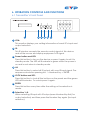
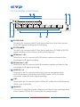
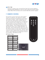
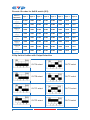
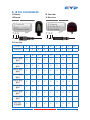
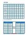
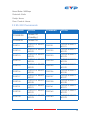
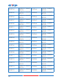
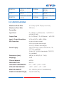
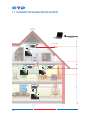
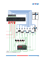
PU-8H8CTXIR
8-Way HDMI HDBaseT™
Transmitter with 8x8 IR Matrix
(inc. POE)
OPERATION MANUAL
DISCLAIMERS
The information in this manual has been carefully checked and
is believed to be accurate. Cypress Technology assumes no
responsibility for any infringements of patents or other rights of third
parties which may result from its use.
Cypress Technology assumes no responsibility for any inaccuracies
that may be contained in this document. Cypress also makes no
commitment to update or to keep current the information contained
in this document.
Cypress Technology reserves the right to make improvements to this
document and/or product at any time and without notice.
COPYRIGHT NOTICE
No part of this document may be reproduced, transmitted,
transcribed, stored in a retrieval system, or any of its part translated
into any language or computer file, in any form or by any means—
electronic, mechanical, magnetic, optical, chemical, manual, or
otherwise—without express written permission and consent from
Cypress Technology.
© Copyright 2011 by Cypress Technology.
All Rights Reserved.
Version 1.0 September 2011
TRADEMARK ACKNOWLEDGMENTS
All products or service names mentioned in this document may be
trademarks of the companies with which they are associated.
SAFETY PRECAUTIONS
Please read all instructions before attempting to unpack, install or
operate this equipment and before connecting the power supply.
Please keep the following in mind as you unpack and install this
equipment:
•
Always follow basic safety precautions to reduce the risk of fire,
electrical shock and injury to persons.
•
To prevent fire or shock hazard, do not expose the unit to rain,
moisture or install this product near water.
•
Never spill liquid of any kind on or into this product.
•
Never push an object of any kind into this product through any
openings or empty slots in the unit, as you may damage parts
inside the unit.
•
Do not attach the power supply cabling to building surfaces.
•
Use only the supplied power supply unit (PSU). Do not use the PSU
if it is damaged.
•
Do not allow anything to rest on the power cabling or allow any
weight to be placed upon it or any person walk on it.
•
To protect the unit from overheating, do not block any vents or
openings in the unit housing that provide ventilation and allow for
sufficient space for air to circulate around the unit.
REVISION HISTORY
VERSION NO.
DATE
SUMMARY OF CHANGE
RDV1
11/11/2011
PreliMINary Release
CONTENTS
1. Introduction���������������������������������������������� 1
2. Applications��������������������������������������������� 1
3. Package Contents���������������������������������� 1
4. System Requirements������������������������������ 1
5. Features���������������������������������������������������� 2
6. Operation Controls and Functions��������� 3
6.1 Transmitter’s Front Panel��������������������3
6.2 Transmitter’s Rear Panel��������������������4
7. Remote Control���������������������������������������� 5
8. IR Pin Assignment������������������������������������ 7
9. RS-232 Protocols�������������������������������������� 8
9.1Pin Assignment������������������������������������8
9.2 RS-232 Commands�����������������������������9
10. Specifications�������������������������������������� 11
11. Connection and Installation��������������� 12
12. Acronyms��������������������������������������������� 14
1. INTRODUCTION
The HDMI over CAT6 transmitter with IR Matrix is an outstanding device
for extending and controlling your HDMI signal. With 8 HDMI input
ports and 8 CAT6 output ports this device allows a great amount of
sources and display to be controlled and display up to 100 meters
away. Moreover, with control systems such as IR, RS-232 and remote
control these easy users with all kinds of control habit and occasion.
Further, the IR matrix makes the distance control over both source and
display even more freely and easily.
2. APPLICATIONS
• Commercial advertising and displaying
• Lecture room display and control
• Hyper market demonstration and control
3. PACKAGE CONTENTS
• HDMI over CAT6 with 8 x 8 IR Matrix
• Receiver for HDMI Over CAT6 x 8 (Optional)
• IR Extender x 9
• IR Blaster x 9
• 24V/6.25A DC adaptor x 1
• 5V/6A DC adaptor x 1
• Remote control x 1
• Operation manual
4. SYSTEM REQUIREMENTS
• Input source equipments with HDMI connection cables
• Industry CAT5e/6/7 cable.
• Output display or audio receiver equipments with HDMI
connection cables.
1
5. FEATURES
• HDMI, HDCP1.1 and DVI compliant
• Supports HDMI v1.4 features:
• 3D
• Supports Stereo audio input and output, analog and digital audio
signal
• Supports high bit rate audio up to 192kHz
• Supports resolutions to VGA ~ WUXGA and 480i~1080p follow by
output display’s EDID
• Supports extension up to 80 meters through CAT5e or 100 meters
through CAT6/7
• Supports 3D signal display follow by display TV’s EDID
• Supports HDMI input up to 15 meters with 8bits resolution or 10
meters with 12bits resolution
• Supports IR in/out from input and output side
• Supports RS-232, remote control and on panel control
• 2U size design
2
6. OPERATION CONTROLS AND FUNCTIONS
6.1 Transmitter’s Front Panel
1
2 3 4 5
6
7
1 LCM:
This monitor displays your setting information of each IR’s input and
output selection.
2 IR:
This IR window accepts the remote control signal of this device
and all the source and display equipment’s IR signal.
3 Power button and LED:
Press this button to turn on the device or press it again to set it to
standby mode. The LED will illuminate in green when the power is
on and in red when in standby mode.
4 All:
Press this button to select all IR output with one IR input signal. The
sequence should be pressing ALL → Number Key → ENTER.
5 LOCK button and LED:
Press this button to lock all the buttons on the panel and the green
LED will illuminate. To unlock press it again.
6 ENTER:
Press this button every time after the setting or the selection is
made.
7 Selection 1~8:
When selecting IR input with IR output press Number Key first (for
output selection) and then press the Number Key again (for input
selection).
3
6.2 Transmitter’s Rear Panel
3
1 2
4
7 8
5
6
1 RS-232 AUX:
This slot is to connect with D-Sub 9pin cable from the third device
for RS-232 signal sending and controlling.
2 RS-232 MAIN:
This slot is to connect with D-Sub 9pin cable from PC/NB for RS-232
signal sending to the device and the third device.
3 IR Blaster 1~All:
These slots are to connect with IR blaster cables included in the
package for IR signal sending.
4 IR Extender 1~All:
These slots are to connect with IR extender cables included in the
package for IR signal receiving.
5 HDMI IN 1~8:
These slots are to connect with input source equipment such
as DVD player or Set-Up-Box with HDMI cable or DVI to HDMI
converter cable for input signal sending.
6 CAT:
These slots are to connect with CAT5e/6/7 cable from the Receiver
HDMI Over CAT6 side.
7 MAIN 5V:
This slot is to plug the power adaptor included in the package and
then connect to the AC wall outlet for power supply.
4
8 POE / 24V:
This slot is where user connect the 24V DC power adaptor
and plug the adaptor to an AC wall outlet for power supply
when the CAT 6 out are not connected with power supply.
7. REMOTE CONTROL
This remote control can be set with multipal
format according to the dipswitch setting.
There are total of four dipswitches with mainly
two kinds of settings. When dipswitches are
all set to ON/↑ the remote control is able to
control all outputs and all inputs. For example,
when output A wish to select input 5. Press 1
first and wait for a second then press 5, the
output display A will display input source 5’s
image instantly. Other settings referring to IR
Dip Switch Position with Output Selection. For
example, when all dipswitches are set to OFF/↓
this setting is base on output A and therefore, it
can only control inputs selection. Hence, when
output A wish to selelct input 3 press 3 only will
switch output display A to display input source
3’s contents.7.1 RS-232 Protocols
IR Custom Code
NO.
DATA
1
88
2
89
3
8A
4
8C
5
8D
6
8E
7
90
8
91
9
92
0
95
5
Discrete IR codes for 8x8 IR matrix (IR3)
Select /
Dipswitch
input 1
input 2
input 3
input 4
input 5
input 6
input 7
input 8
output A
↓↓↓↓
0cx88
0x89
0x8A
0x8C
0x8D
0x8E
0x90
0x91
output B
↑↓↓↓
0x88
0x89
0x8A
0x8C
0x8D
0x8E
0x90
0x91
output C
↓↑↓↓
0x88
0x89
0x8A
0x8C
0x8D
0x8E
0x90
0x91
output D
↑↑↓↓
0x88
0x89
0x8A
0x8C
0x8D
0x8E
0x90
0x91
output E
↓↓↑↓
0x88
0x89
0x8A
0x8C
0x8D
0x8E
0x90
0x91
output F
↑↓↑↓
0x88
0x89
0x8A
0x8C
0x8D
0x8E
0x90
0x91
output G
↓↑↑↓
0x88
0x89
0x8A
0x8C
0x8D
0x8E
0x90
0x91
output H
↑↑↑↓
0x88
0x89
0x8A
0x8C
0x8D
0x8E
0x90
0x91
IR Dip Switch Position with Output Selection
6
OUTA select
OUTE select
OUTB select
OUTF select
OUTC select
OUTG select
OUTD select
OUTH select
8. IR PIN ASSIGNMENT
IR Blaster
IR Extender
IR Blaster
IR Receiver
① IR signal
② Power 5V
① Power 5V
② NC
③ Grounding
③ IR blaster signal
①②③
①③ ②
IR Function
OUT(TV)
A
B
C
D
E
F
G
H
IN(DVD)
1
2
3
4
5
6
7
8
A
B
C
D
E
F
G
H
DVD1 有信
號時
O
X
X
X
X
X
X
X
DVD2 有信
號時
X
O
X
X
X
X
X
X
DVD3 有信
號時
X
X
O
X
X
X
X
X
DVD4 有信
號時
X
X
X
O
X
X
X
X
DVD5 有信
號時
X
X
X
X
O
X
X
X
DVD6 有信
號時
X
X
X
X
X
O
X
X
DVD7 有信
號時
X
X
X
X
X
X
O
X
DVD8 有信
號時
X
X
X
X
X
X
X
O
DVD ALL
有信號時
O
O
O
O
O
O
O
O
ALL
7
1
2
3
4
5
6
7
8
ALL
TVA 有信號
時
O
X
X
X
X
X
X
X
O
TVB 有信號
時
X
O
X
X
X
X
X
X
O
TVC 有信
號時
X
X
O
X
X
X
X
X
O
TVD 有信
號時
X
X
X
O
X
X
X
X
O
TVE 有信號
時
X
X
X
X
O
X
X
X
O
TVF 有信號
時
X
X
X
X
X
O
X
X
O
TVG 有信
號時
X
X
X
X
X
X
O
X
O
TVH 有信
號時
X
X
X
X
X
X
X
O
O
9. RS-232 PROTOCOLS
9.1Pin Assignment
CSI-8H8CV2IR
8
Remote Control Console
PIN
Assignment
PIN
Assignment
1
NC
1
NC
2
TX
2
RX
3
RX
3
TX
4
NC
4
NC
5
GND
5
GND
6
NC
6
NC
7
NC
7
NC
8
NC
8
NC
9
NC
9
NC
Baud Rate: 9600bps
Data bit: 8 bits
Parity: None
Flow Control: None
9.2 RS-232 Commands
COMMAND
ACTION
COMMAND
ACTION
POWER 00
Power Off
(standby)
POWER 01
Power On
PORT 11
OUTPUT A SELECT
PORT 21
INPUT1
OUTPUT B SELECT
INPUT1
PORT 12
OUTPUT A SELECT
PORT 22
INPUT2
OUTPUT B SELECT
INPUT2
PORT 13
OUTPUT A SELECT
PORT 23
INPUT3
OUTPUT B SELECT
INPUT3
PORT 14
OUTPUT A SELECT
PORT 24
INPUT4
OUTPUT B SELECT
INPUT4
PORT 15
OUTPUT A SELECT
PORT 25
INPUT5
OUTPUT B SELECT
INPUT5
PORT 16
OUTPUT A SELECT
PORT 26
INPUT6
OUTPUT B SELECT
INPUT6
PORT 17
OUTPUT A SELECT
PORT 27
INPUT7
OUTPUT B SELECT
INPUT7
PORT 18
OUTPUT A SELECT
PORT 28
INPUT8
OUTPUT B SELECT
INPUT8
PORT 31
OUTPUT C SELECT
PORT 41
INPUT1
OUTPUT D SELECT
INPUT1
PORT 32
OUTPUT C SELECT
PORT 42
INPUT2
OUTPUT D SELECT
INPUT2
PORT 33
OUTPUT C SELECT
PORT 43
INPUT3
OUTPUT D SELECT
INPUT3
9
PORT 34
OUTPUT C SELECT
PORT 44
INPUT4
OUTPUT D SELECT
INPUT4
PORT 35
OUTPUT C SELECT
PORT 45
INPUT5
OUTPUT D SELECT
INPUT5
PORT 36
OUTPUT C SELECT
PORT 46
INPUT6
OUTPUT D SELECT
INPUT6
PORT 37
OUTPUT C SELECT
PORT 47
INPUT7
OUTPUT D SELECT
INPUT7
PORT 38
OUTPUT C SELECT
PORT 48
INPUT8
OUTPUT D SELECT
INPUT8
PORT 51
OUTPUT E SELECT
PORT 61
INPUT1
OUTPUT F SELECT
INPUT1
PORT 52
OUTPUT E SELECT
PORT 62
INPUT2
OUTPUT F SELECT
INPUT2
PORT 53
OUTPUT E SELECT
PORT 63
INPUT3
OUTPUT F SELECT
INPUT3
PORT 54
OUTPUT E SELECT
PORT 54
INPUT4
OUTPUT F SELECT
INPUT4
PORT 55
OUTPUT E SELECT
PORT 65
INPUT5
OUTPUT F SELECT
INPUT5
PORT 56
OUTPUT E SELECT
PORT 66
INPUT6
OUTPUT F SELECT
INPUT6
PORT 57
OUTPUT E SELECT
PORT 67
INPUT7
OUTPUT F SELECT
INPUT7
PORT 58
OUTPUT E SELECT
PORT 68
INPUT8
OUTPUT F SELECT
INPUT8
PORT 71
OUTPUT G SELECT
PORT 81
INPUT1
OUTPUT H SELECT
INPUT1
PORT 72
OUTPUT G SELECT
PORT 82
INPUT2
OUTPUT H SELECT
INPUT2
PORT 73
OUTPUT G SELECT
PORT 83
INPUT3
OUTPUT H SELECT
INPUT3
PORT 74
OUTPUT G SELECT
PORT 84
INPUT4
OUTPUT H SELECT
INPUT4
PORT 75
OUTPUT G SELECT
PORT 85
INPUT5
OUTPUT H SELECT
INPUT5
10
PORT 76
OUTPUT G SELECT
PORT 86
INPUT6
OUTPUT H SELECT
INPUT6
PORT 77
OUTPUT G SELECT
PORT 87
INPUT7
OUTPUT H SELECT
INPUT7
PORT 78
OUTPUT G SELECT
PORT 88
INPUT8
OUTPUT H SELECT
INPUT8
10. SPECIFICATIONS
Maximum Data Rate
6.75 Gbps (2.25 Gbps per clock)
Maximum Pixel Rate
225 MHz
Transmitter
Input Ports
8 x HDMI, 9 x IR Extender, 1 x RS-232, 1
x WAN (RJ-45)
Output Ports
8 x CAT5e/6/7, 9 x IR Blaster, 1 x RS-232
Input / Output Resolution
VGA~WUXGA, 480i~1080p
ESD Protection
Human body model:
± 8kV (Air-gap discharge)
± 4kV (Contact discharge)
Power Supply
24V/6.25A DC (US/EU standards, CE/
FCC/UL certified)
5V/6A DC (US/EU standards, CE/FCC/
UL certified)
Dimensions (mm)
482(W) X 362.5(D) X 176(H)
Weight(g)
2100
Chassis Material
METAL
Silkscreen Color
BLACK
OPERATING TEMPERATURE
0ºC ~ 40ºC / 32ºF ~ 104ºF
STORAGE TEMPERATURE
-20ºC ~ 60ºC / -4ºF ~ 140ºF
RELATIVE HUMIDITY
20 ~ 90% RH (NON-CONDENSING)
POWER CONSUMPTION(W)
90 (INCLUDE RX)
11
11. CONNECTION AND INSTALLATION
1
2
3
4
RS-232
Command
A A B B C
CH-1109RXC A
CAT-6 100m
HDMI
HDMI
CH-1109RXC B
CH-1109RXC C
HDMI
HDMI
CH-1109RXC D
HDMI
RS-232
Command
12
HDMI
3M
1
2
3
4
5
6
7
3M
30°
8
30°
7M
RS-232
Command
CSI-8H8CV2IR
A A B B C C D D
HDMI
HDMI
HDMI
HDMI
HDMI
HDMI
HDMI
HDMI
H
HDMI Cable
HDMI
RS-232
Command
G
HDMI
F
HDMI
H G F E
D C B A
HDMI
HDMI
HDMI
HDMI
E
HDMI
CMLUX-88S
HDMI Cable
RS-232 Cable
13
12. ACRONYMS
ACRONYM
COMPLETE TERM
DTS
Digital Theater System
DVI
Digital Visual Interface
EDID
Extended Display Identification Data
HDCP
High-bandwidth Digital Content Protection
HDMI
High-Definition Multimedia Interface
HDTV
High-Definition Television
LCM
Liquid Crystal Monitor
USB
Universal Serial Bus
UXGA
Ultra Extended Graphics Array
VGA
Video Graphics Array
14
www.cypeurope.com