1
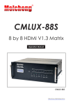
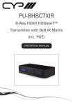
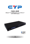
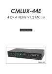
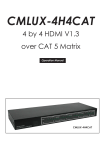
CMLUX-88S 8 by 8 HDMI V1.3 Matrix Operation Manual CMLUX-88S Disclaimers The information in this manual has been carefully checked and is believed to be accurate. Cypress Technology assumes no responsibility for any infringements of patents or other rights of third parties which may result from its use. Cypress Technology assumes no responsibility for any inaccuracies that may be contained in this document. Cypress also makes no commitment to update or to keep current the information contained in this document. Cypress Technology reserves the right to make improvements to this document and/or product at any time and without notice. Copyright Notice No part of this document may be reproduced, transmitted, transcribed, stored in a retrieval system, or any of its part translated into any language or computer file, in any form or by any means - electronic, mechanical, magnetic, optical, chemical, manual, or otherwise - without express written permission and consent from Cypress Technology. © Copyright 2009 by Cypress Technology. All Rights Reserved. Version 1.0 August 2009 Trademark Acknowledgments All products or service names mentioned in this document may be trademarks of the companies with which they are associated. Safety Precautions Please read all instructions before attempting to unpack or install or operate this equipment, and before connecting the power supply. Please keep the following in mind as you unpack and install this equipment: Always follow basic safety precautions to reduce the risk of fire, electrical shock and injury to persons. To prevent fire or shock hazard, do not expose the unit to rain, moisture or install this product near water. Never spill liquid of any kind on or into this product. Never push an object of any kind into this product through module openings or empty slots, as you may damage parts. Do not attach the power supply cabling to building surfaces. Do not allow anything to rest on the power cabling or allow it to be abused by persons walking on it. To protect the equipment from overheating, do not block the slots and openings in the module housing that provide ventilation. Revision History Version No V1 V2 Date 20090805 20100510 Summary of Change Preliminary Release Rack Installation change Table of Contents I. Rack Installation Guideline ..………...……………...…........….…… 1 1. Introduction ……………………..……………………...…........….……. 2 2. Applications …………………..………………….……...................….. 2 3. Package Contents ………………………...........……….................… 2 4. System Requirements ……………..……….........………............……. 2 5. Features …………………………………………......……........…...…… 3 6. Specifications ………………………………...……..........………....…. 4 7. Operation Controls and Functions ……………...……..............…… 7.1 Front Panel .............................................................................. 5 7.2 Rear Panel .…………………………………..…….......…...….… 7 Remote Control .......................…......……………..........…..…....…... 8 8.1 IR Costom Code.................…......……………..........…..…....…. 8 8.2 Discrete IR codes for 8x8 HDMI matrix (IR3).........…..…....…... 8 IR Pin Assignment ............................................................................. 9 9.1 IR Receiver ............................................................................... 9 RS-232 Protocols ……………...……........……................................… 10.1 Pin Assignment ...................................................................... 9 8. 9. 10. 10.2 5 9 Commands ………...……………….………….........……....… 10 11. Connection and Installation ….………………….........…..…..…...... 12 12. Acronyms …...................................................................................... 13 I. Rack Installation Guideline A L-Shaped rail x 2 B Mounting screws x 4 C Flanged screws x 4 A B B X4 ① Use Mounting screws to ② Make sure the L-Shaped rail and the attach the L-Shape rail Mounting screws are properly aligned, to the frame. with two screws per L-Shaped rail. A A CMLUX-88S ③ Slide the device on top of the L-Shaped rails. C CMLUX-88S 8x8 HDMI v1.3 MATRIX OUT A B C D E F G H IN 1 2 3 4 5 6 7 8 EDID LOCK ENTER ALL MEMORY RECALL POWER C ④ Use four Flanged screws to attach the 8x8 Matrix to the rack frame. 1 1. Introduction The popularity of HDMI products has been increasing for several years and is now commonly seen in residential and commercial settings. As people become accustomed to HDMI and use it more often, they acquire multiple devices and then find that they need something to help them link them together. So the need for an HDMI matrix that can interconnect multiple sources and different inputs has become an obsession for some. Well no need to worry because our “HDMI V1.3 Matrix” is a powerful tool that you can use to handle all of your HDMI needs. Furthermore the matrix supports HDMI 1.3, HDCP 1.1 and DVI 1.0, and can transfer Deep Color video and bit stream digital audio with fantastic performance. Lastly the input EDID is independent allowing each input to switch between TV or the built-in EDID. 2. Applications Multi-HDMI sources with multi-HDMI display controls Event entertainment integration Multi-task project presentation Showroom display Advertisement display control 3. Package Contents 8 by 8 HDMI V1.3 Matrix Remote Control CR-71 with battery 24V DC power adaptor Power cord User Manual 2 x 2 - Shape holder 4. System Requirements HDMI input device(s) and HDMI output device(s) with HDMI cables. 2 5. Features HDMI 1.3, HDCP 1.1 and DVI 1.0 compliant Supports digital video formats in Deep Color 10 bits and new lossless compressed (Dolby TrueHD, Dolby Digital Plus and DTS HD Master Audio) digital audio The HDMI input is compensated, clock/phase adjusted and jitter free so all the user sees is a high quality HDMI signal. Supports recall, memory and key lock function Compatible with all HDMI sources and displays Supports a wide range of PC and HDTV resolutions from VGA to UXGA and 480i to 1080p Supports RS-232 control and firmware upgrading through USB port Supports IR remote control and IR extender Dolby Digital, DTS digital audio transmission (32-192kHz Fs sample rate) Supports LPCM 7.1 channel output from each of the independent HDMI ports HDMI cable testing showed that with a resolution 1080p/8bits&10bits the Input/Output source can be 10/15m(8bit) and 10/10m(10) away Independent switchable EDID function for choosing which resolution to display High performance HDMI 1.3 Matrix with 8 (eight) inputs and 8 (eight) outputs with a remote control in order to link multiple HDMI sources, such as movies, music and games, all at the same time. Supports 38KHz IR extender 4U's rack design for easy installation Useful hot keys for quick set up Strong build quality and an intelligent design allow the HDMI V1.3 Matrix to breathe properly and not overheat 3 6. Specifications Input Ports 8 x HDMI Output Ports 8 x HDMI IR Frquency 20~60KHz Power Supply 24VDC/6.25A (US/EU standards, CE/FCC/UL certified) ESD Protection Human body model: ± 10kV (air-gap discharge) ± 6kV (contact discharge) Dimensions (mm) 482(W) x385(D) x 176(H) Weight(g) 9500 Chassis Material Aluminum Silkscreen Color Metal Black Power Consumption 100W Operating Temperature 0˚C ~ 40˚C / 32˚F ~ 104˚F Storage Temperature -20˚C ~ 60˚C / -4˚F ~ 140˚F Relative Humidity 20~90% RH (no condensation) 4 7. Operation Controls and Functions The following sections describe the hardware components of the unit. 7.1 Front Panel ① ② ③ ④ ⑤ ⑥ ⑦ ⑧ ⑨ ⑩ ① LCM monitor: This monitor displays your settings information with each output and input selection. ② IR sensor. ③ POWER: Press this button to turn the system on. Once the system turns on the LED will turn Green and when entering Standby Mode it will turn Red. Once the system turns on the LED will turn Green and when entering Standby Mode it will turn Red. ④ EDID: There will be two selections shown on the LCM: 1. TV mode and 2.Standard Mode, press the number key to first select the desired input and then press one or two to select the EDID mode. The LED will turn on when setting the EDID. After the selection is made, press enter key to confirm. Standard mode means the device will use internal built-in EDID and TV mode means the device will use TV/display’s EDID. When EDID is in TV mode, Notes: 1. When EDID is switched to a TV the device will first detect the HDMI output source’s EDID from A-D and then record it in the unit regardless of the HDMI output source from E-H. If the first detected output source is DVI it will pass on to the next source, until the first HDMI is detected. The detection priority is HDMI v1.3 > HDMI v1.2 > DVI. In order to ensure all output is displayable output from E-H must be of a lower standard then output from A-D. 2. When EDID is on STD, the device will use the built-in EDID Video Supports < 1080p 10 bits (max) Audio Supports = PCM2 5 ⑤ LOCK: Press this button to lock all the functions and press it again to release the lock. When LED turns Green, the lock is activated and when it turns red the key lock has been released. ⑥ ENTER: Press this button after each and every selection to confirm the setting. If this button is not pressed after 20 seconds the selection will be cancelled. ⑦ ALL: Press this button to set all the outputs to display with the same input. After pressing the All button press an input number and then press enter to confirm the selection. ⑧ MEMORY: Press this button to choose your six pre-set settings. First press the setting number, and when all the input/outputs are being set, be sure to press MEMORY to record it into the system. The factory default settings are 1.12345678, 2.87654321, 3.11223344, 4.55667788, 5.11221122, 6.33443344. ⑨ RECALL: Select this button in order to retrieve your six pre-set settings, then press enter to confirm your selection. ⑩ OUT A~H & IN 1~8: Press the output source selection button in order to choose which input port corresponds to the desired output port. First select your output port from A-H, wait 2 sec, then choose the desired input port from ports 1-8, pressing enter will confirm your setting. Each output selection only allows a single input setting each time. 6 7.2 Rear Panel ①② ③ ④ ⑤ ⑥ ⑦ ① HDMI OUTPUT A~H: These slots are where you connect the HDMI displays. ② SERVICE: This slot is where you connect a D-sub 9 male pin connector cable to your host, in order to upgrade your firmware. ③ RS-232: This slot is where you connect a D-sub 9 female pin connector cable to your host so you can control an 8x8 HDMI Matrix. ④ USB SERVICE: This slot is where you connect a USB b type connector cable to your host for ISP (System Program) firmware burning, for a total of four. ⑤ IR IN: This slot is where you can extend your IR receiver with an IR extender cable that accepts only 38KHz. ⑥ HDMI INPUT 1~8: These slots are where you connect the output cable of your HDMI or DVI source, such as DVD players or Set Top Boxes. ⑦ DC 24V: Plug the 24V DC power supply into the unit and connect the adaptor to an AC wall outlet. 7 8. Remote Control This remote control can be set with multipal format according to the dipswitch setting. There are total of four dipswitches with mainly two kinds of settings. When dipswitches are all set to ON/↑ the remote control is able to control all outputs and all inputs. For example, when output A wish to select input 5. Press 1 first and wait for a second then press 5, the output display A will display input source 5’s image instantly. Other settings referring to below section 8.2 section 8.2 are output based to control input selections. For example, when all dipswitches are set to OFF/↓ this setting is base on output A and therefore, it can only control inputs selection. Hence, when output A wish to selelct input 3 press 3 only will switch output display A to display input source 3’s contents. Further setting please refers to section 8.2. 1 2 3 4 5 6 7 8 9 0 CR-71 8.1 IR Custom Code NO. 1 2 3 4 5 6 7 8 9 0 DATA 88 89 8A 8C 8D 8E 90 91 92 95 8.2 Discrete IR codes for 8x8 HDMI matrix (IR3) Select / Dipswitch output A ↓↓↓↓ input 1 0cx88 input 2 0x89 input 3 0x8A input 4 0x8C input 5 0x8D input 6 0x8E input 7 0x90 input 8 0x91 output B ↑↓↓↓ 0x88 0x89 0x8A 0x8C 0x8D 0x8E 0x90 0x91 output C ↓↑↓↓ 0x88 0x89 0x8A 0x8C 0x8D 0x8E 0x90 0x91 output D ↑↑↓↓ 0x88 0x89 0x8A 0x8C 0x8D 0x8E 0x90 0x91 output E ↓↓↑↓ 0x88 0x89 0x8A 0x8C 0x8D 0x8E 0x90 0x91 output F ↑↓↑↓ 0x88 0x89 0x8A 0x8C 0x8D 0x8E 0x90 0x91 output G ↓↑↑↓ 0x88 0x89 0x8A 0x8C 0x8D 0x8E 0x90 0x91 output H ↑↑↑↓ 0x88 0x89 0x8A 0x8C 0x8D 0x8E 0x90 0x91 8 9. IR Pin Assignment 9.1 IR Receiver ① IR signal ② Power 5V ③ Grounding ① ②③ 10. RS-232 Protocols 10.1 Pin Assignment CMLUX-88S Remote Control Console PIN Assignment PIN Assignment 1 NC 1 NC 2 Tx 2 Rx 3 Rx 3 Tx 4 NC 4 NC 5 GND 5 GND 6 NC 6 NC 7 NC 7 NC 8 NC 8 NC 9 NC 9 NC Baud Rate: 9600bps Data bit: 8 bits Parity: None Flow Control: None 9 10.2 Commands COMMAND ACTION POWER 00 Power Off (standby) POWER 01 Power On PORT 11 Output A select Input1 PORT 12 Output A select Input2 PORT 13 Output A select Input3 PORT 14 Output A select Input4 PORT 15 Output A select Input5 PORT 16 Output A select Input6 PORT 17 Output A select Input7 PORT 18 Output A select Input8 PORT 21 Output B select Input1 PORT 22 Output B select Input2 PORT 23 Output B select Input3 PORT 24 Output B select Input4 PORT 25 Output B select Input5 PORT 26 Output B select Input6 PORT 27 Output B select Input7 PORT 28 Output B select Input8 PORT 31 Output C select Input1 PORT 32 Output C select Input2 PORT 33 Output C select Input3 PORT 34 Output C select Input4 PORT 35 Output C select Input5 PORT 36 Output C select Input6 PORT 37 Output C select Input7 PORT 38 Output C select Input8 PORT 41 Output D select Input1 PORT 42 Output D select Input2 PORT 43 Output D select Input3 PORT 44 Output D select Input4 PORT 45 Output D select Input5 PORT 46 Output D select Input6 10 PORT 47 Output D select Input7 PORT 48 Output D select Input8 PORT 51 Output E select Input1 PORT 52 Output E select Input2 PORT 53 Output E select Input3 PORT 54 Output E select Input4 PORT 55 Output E select Input5 PORT 56 Output E select Input6 PORT 57 Output E select Input7 PORT 58 Output E select Input8 PORT 61 Output F select Input1 PORT 62 Output F select Input2 PORT 63 Output F select Input3 PORT 64 Output F select Input4 PORT 65 Output F select Input5 PORT 66 Output F select Input6 PORT 67 Output F select Input7 PORT 68 Output F select Input8 PORT 71 Output G select Input1 PORT 72 Output G select Input2 PORT 73 Output G select Input3 PORT 74 Output G select Input4 PORT 75 Output G select Input5 PORT 76 Output G select Input6 PORT 77 Output G select Input7 PORT 78 Output G select Input8 PORT 81 Output H select Input1 PORT 82 Output H select Input2 PORT 83 Output H select Input3 PORT 84 Output H select Input4 PORT 85 Output H select Input5 PORT 86 Output H select Input6 PORT 87 Output H select Input7 PORT 88 Output H select Input8 11 11. Connection and Installation HD TV HD TV STB HD TV DVD Blu-ray HD TV PS3 Blu-ray HD TV PS3 HD TV STB HD TV HD TV 12 DVD A Acronyms Acronym Complete Term DTS Digital Theater System DVI Digital Visual Interface EDID Extedned Display Identification Data HDCP High-bandwidth Digital Content Protection HDMI High-Definition Multimedia Interface HDTV High-Definition Television LCM Liquid Crystal Monitor USB Universal Serial Bus UXGA Ultra Extended Graphics Array VGA Video Graphics Array 13 CYPRESS TECHNOLOGY CO., LTD. Home page: http://www.cypress.com.tw 20090918 MPM-CMLUX88S