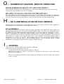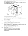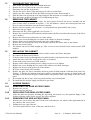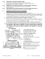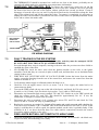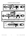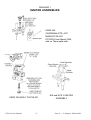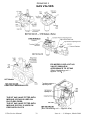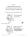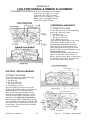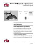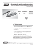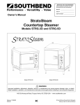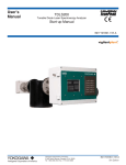
1
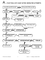
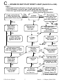
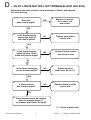
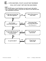
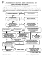
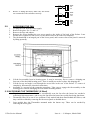
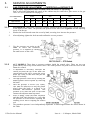
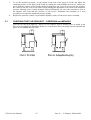
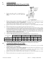
SERVICE
MANUAL
for
CARDRONA
MONACO Series 2
PICCOLO
SOFIA
MADRID
GAS FIRES
TO BE USED ONLY BY AUTHORISED PERSONNEL
Part No 591402
CONTENTS
TROUBLESHOOTING
A.
Ba.
Bb.
C.
D.
E.
F.
G.
H.
I.
Page
Pilot will not light after repeated attempts........................................................... 2
EIS fire won’t light after repeated attempts ........................................................ 3
ECS II fire won’t light after repeated attempts.................................................... 4
Spark OK, but pilot won’t light (not ECS II or EIS)........................................... 5
Pilot lights but will not remain alight (not ECS) .................................................. 6
Standard heaters. Pilot alight but burner will not light within 10 seconds............. 7
Thermostat heaters. Pilot alight but burner won’t light in 30 seconds.................. 8
Thermostat heaters. Erratic operation................................................................. 9
No flame modulation on ECS II models.............................................................. 9
Sooting .............................................................................................................. 9
CARDRONA & MONACO S2 ASSY AND DIS-ASSEMBLY
Removing and fitting glass, louvre assembly, dress guard, front panel.....................10, 11
Disconnecting the flue................................................................................................. 12
Removing and replacing the cabinet............................................................................. 12
Access panels, removing and replacing ...................................................................12, 13
Removing and replacing the burner ............................................................................. 13
Removing and replacing the pilot assembly and pilot jet............................................... 14
Accessing the main injector ......................................................................................... 14
Removing control valves and regulators .................................................................14, 15
Accessing the fan assembly.......................................................................................... 15
Removing and replacing the pedestal and pedestal foot................................................ 15
Accessing the thermodisc ............................................................................................ 15
PICCOLO, SOFIA & MADRID ASSY AND DIS-ASSEMBLY
Removing and replacing the glass................................................................................ 16
Fitting louvre assemblies and dress guards..............................................................16, 17
Removing and replacing the burner ............................................................................. 17
Removing and replacing the pilot assembly.................................................................. 18
Accessing the main injector ........................................................................................ 18
Accessing the control valve ......................................................................................... 18
Removing and replacing the fascia............................................................................... 18
Accessing the fan ........................................................................................................ 19
Accessing the thermodisc ............................................................................................ 19
SERVICE ADJUSTMENTS
Gas pressure adjustment...................................................................................20, 21, 22
Checking the flue draught............................................................................................ 22
Converting Cardrona and Monaco fires ..................................................................23, 24
Converting Piccolo, Sofia and Madrid fires.............................................................24, 25
Remote control installation (ACC and EIS models) ..................................................... 25
ECS II information.................................................................................................26, 27
EIS information......................................................................................................27, 28
EIS fault tracing.....................................................................................................28, 29
Further wiring diagrams .............................................................................................. 30
DRAWINGS
Igniter assemblies........................................................................................................ 31
Gas valves................................................................................................................... 32
Testing pilot gas flow.................................................................................................. 33
Log positions and ember placement ............................................................................. 34
Rear views .............................................................................................................35, 39
TABLES
Table 1........................................................................................................................ 40
G.Fire Service Manual
1
Issue A — © Masport, March 2004
A
— PILOT WILL NOT LIGHT AFTER REPEATED ATTEMPTS
YES
Is it an EIS or an ECS II model?
EIS,
EIS,go
goto
toBa:
Ba:ECS
ECSII,II,go
goto
toBb
Bb
NO
Has it Battery
battery
ignition?
YES
Is
Isthere
thereaaspark
sparkat
at NO
the
theigniter?
igniter?
Replace battery,
check battery
contacts
NO
YES
NO
1 Does the
Piezo 'click'?
Wiring OK
Go to A3
NO
YES
Go to
A3
Spark?
Check
switch
wiring
Switch OK
Check switch
at valve
52 Replace
Replace
Piezo,
Piezo,
gogo
to to
A1A1
YES
6
3 Is
Is there
there aa spark
spark
at
at the
the igniter?
igniter?
NO
74 Is there carbon YES
on the pilot head?
8
5
Clean
and
gogo
to to
A6A3
Clean
and
YES
9
6 A
A strong
strong spark
every time?
time?
NO. Go to A8
YES
10
7 Spark
SparkOK.
OK.Go
Goto
toC
C
to
tocheck
checkgas
gassupply
supply
NO
8 IsIsthe
11
thespark
sparkgap
gapcorrect?
correct?
See
Drawing
No.
See Drawing No 1?
12
9 Replace
Replace electrode
electrode assembly.
assembly.
Go
Go to
to A6
A9
NO
YES
10 Are all connecting wires
secure at both ends?
16
13
YES
14
11 IsIsthe
thehigh
hightension
tensionwire
wire
shorting
to
the
shorting to theheater?
heater?
YES
NO
NO
Fix.
Fix.Go
Goto
toA9
A6
17
14 Is
YES
Is the
the electrode
electrode
insulator cracked?
cracked?
insulator
15
12 Replace
Replacewire.
wire.
GototoA9
A6
Go
15
18 Replace
Replace electrode
electrode
assembly.
assembly.
Go to
to A9
A6
Go
NO
19
16 Fit
Fitnew
newPiezo
Piezoor
or
batteryignition
ignitionmodule.
module.
battery
Goto
toA9
A6
Go
G.Fire Service Manual
2
Issue A — © Masport, March 2004
Ba
— EIS FIRE WON'T LIGHT AFTER REPEATED ATTEMPTS
Note: These fires have no standing pilot. The burner lights each time the heat is called for.
When operating correctly, the spark ceases as soon as the main burner flame is established.
FIRST:Check that the mains power supply and the gas supply are valid and that any gas valves are open.
1
2
Turn on the flame switch on the side of the fascia
Fit jumper wire across
thermostat terminals.
Fault cleared?
13
NO
Does the spark begin after a few seconds?
YES
3
Check for
wrong polarity
in phase and
neutral of
mains supply
NO
Does the spark cease after
about 30 seconds?
YES
4
14
Faulty thermostat
or room too hot.
OK
Normal
15
5
6
YES
NO
3a
Clean flame sensor
electrode and
check its wiring.
Fire still won't light
after ten attempts?
Check wire connections and
earth return between burner
and valve. Verify ignition loom
plugs are firmly home. If still
no spark, check the spark
electrode insulation and
lead for cracks.
YES
7
Check for gas
OK
pressure at valve outlet
10
FAULTY
8
Continue purging
air by ten further
starting attempts.
16
YES
NO FLAME
Check for gas
pressure at the
valve inlet
11
Clean main
injector.
17
OK
FAULTY
9
12
Faulty gas supply
Faulty valve
G.Fire Service Manual
Faulty ignition module
3
If you are qualified,
check for a mains
signal from the
control box to the
ignition module on
the valve. See 7.3.8
NO
SIGNAL
SIGNAL
19
Still faulty?
18
Faulty control box.
Issue A — © Masport, March 2004
Bb
— ECS II FIRE WON'T LIGHT AFTER REPEATED ATTEMPTS
Note: These fires have no standing pilot. The burner lights each time the heat is called for.
When operating correctly, the spark ceases as soon as the main burner flame is established.
FIRST:Check that the mains power supply and the gas supply are valid and that any gas valves are open.
1
2
Press the ON/OFF button on the remote until MANUAL, AUTO, or PROG is showing.
Is the battery symbol flashing or dead?
YES
3
Replace 2 AAA batteries
NO
6
Handpiece faulty
YES
7
Handpiece OK
NO
4
Press AUTO/MAN until MANUAL shows
5
8
Does the transmit signal on the
handpiece flash momentarily?
Does spark begin
in 7 seconds?
9
for gas pressure at valve outlet
OK
12 Fire
still not alight?
Press ON/OFF
button twice to
repeat ignition cycle.
22
16
FAULTY
17
Has aerial circuit board in control box
been dislodged by pulling on aerial wire?
NO
No flame after
ten cycles?
15 Check
Re-fit curcuit
board inside
control box
and re-test
YES
NO
YES
11 Does spark cease in
30 seconds?(Normal)
NO
11a Check for reversed
neutral and phase in
mains supply
OK
Clean
flame
sensor
13
electrode and
check its wiring.
14
10
If qualified, check for
a mains signal from
the control box to the
ignition module on
the valve.
Continue purging
air by 10 further
starting attempts.
21 Check
wire connections and
earth return between burner
and valve. Verify ignition loom
plugs are firmly home. Check
the control box fuse. If still
no spark, check the spark
electrode insulation and
lead for cracks.
NO SIGNAL
SIGNAL
23
Faulty
control box.
24
Faulty
ignition module
NO FLAME
Check for gas
pressure at the
valve inlet
19
Clean main
injector.
OK
FAULTY
18
20
Faulty gas supply
G.Fire Service Manual
4
Faulty valve
Issue A — © Masport, March 2004
C
— SPARK OK BUT PILOT WON'T LIGHT (Not ECS II or EIS)
FIRST :• Check that all shut-off valves in the gas supply are open.
• For LPG models, check for gas in the bottle and open the bottle valve.
• Check for a gas smell near the pilot, and wait for it to disperse
before starting this procedure.
1 Press control down
in 'Pilot' position and
hold match flame at pilot
Pilot
Ignites
YES
5 Wait several
YES
8
Purge air from
system until pilot
ignites. Go to C2
9
Is flame
weak?
Does pilot
light four out of
five times?
NO
YES
OK for service
11 Is gas pressure
Disconnect control
rod and adapter (*) and
hold valve down in 'Pilot'
position
10
OK after
regulator?
12
NO
See Table No 1
Adjust regulator,
test ignition.
Go to C2
YES
NO
NO
Does match
flame blow
sideways?
14
Is pilot jet
clear?
15
Clean jet and retest. Go to C2
16 Replace jet and
See Drg No 3
re-test. Go to C2
YES
YES
Fit new control
rod. Re-test.
Go to C2
D
NO
Go to A9
17
Go to
Turn pilot OFF
and attempt re-lighting
five times
(without match)
YES
13
NO
6
minutes for
pure gas
See Drg No 3
7
Does flame
remain when knob
is released 15
secs after ignition?
NO
Does match
flame blow
sideways?
N
O
YES
Is flame
satisfactory?
No
Ignition
4
3
2
18
NO
19 Adjust pilot gas
Is pilot jet
correct size?
See Table No 1
YES
flow (*) or replace
Pilot gas filter (*)
Re-test. Go to C2
(*) = Some models only
G.Fire Service Manual
5
Issue A — © Masport, March 2004
D
— PILOT LIGHTS BUT WILL NOT REMAIN ALIGHT (Not ECS)
Disconnect the valve control rod (and adaptor if fitted), and operate
the valve directly.
1
Does the
pilot remain alight?
YES
2
Replace or service
the control rod
and re-test
NO
3
Is the thermocouple
connection tight at
the control valve?
NO
4
Tighten connection
and re-test
YES
5
Is the thermocouple
output at least 15 mV
when the pilot is alight?
YES
6
Replace faulty control
valve and re-test
N
O
7
Is the flame impinging
on the thermocouple?
NO
8
Adjust the pilot
flame size. Go to C11
YES
9
Is there soot on
the thermocouple?
NO
10
Replace thermocouple
and re-test
YES
11 Clean thermocouple and adjust
pilot air mixture sleeve (*)
for cleaner pilot flame. Go to D3
(*) = Some models only
G.Fire Service Manual
6
Issue A — © Masport, March 2004
E
— STD HEATERS, PILOT ALIGHT BUT BURNER
WILL NOT LIGHT WITHIN TEN SECONDS
FIRST :• For an LPG heater, check that there is ample gas in the bottle.
• For a Thermostat heater, verify that the sensor is not warmer than
the temperature set-point.
1
Is the gas pressure low
after the regulator?
YES
2
Adjust the pressure
and re-test
NO
3
4
NO
Are the logs
correctly positioned?
Re-arrange logs
correctly and re-test
See Drawing No 4
YES
5
Are the main burner jets
the correct sizes?
NO
6
Fit correct jets
and re-test
See Table No 3
YES
7
YES
Is a jet blocked?
G.Fire Service Manual
7
8
Clean the jet
and re-test
Issue A — © Masport, March 2004
F
— THERMOSTAT HEATERS. MAIN BURNER WILL NOT
LIGHT WITHIN 30 SECONDS.
ON HEATERS FITTED WITH PILOT LIGHTS, THE PILOT MUST BE ALIGHT BEFORE
THE THERMOSTAT CAN TURN ON THE FIRE.
NOTE: When hand-held remote thermostats are set to MANUAL, they do not operate as thermostats
but give direct control. In the AUTO setting they transmit a thermostat signal to the receiver from time
to time, so there can be some delay, when in this setting, before the fire receives a signal to light or
change flame height (modulate). In the MANUAL setting, there is no time delay for signals to the
receiver.
YES
Is the room temperature
above the set temperature?
1
2
Normal operation
NO
Is the thermostat
sensing temperatures
above room temperatures?
(e.g. the heater or sunlight)
3
4
YES
Move the thermostat
away from heat sources
NO
Is the thermostat a
remote one? ( Hand held
or wall mounted)
5
Ensure that room air
can circulate freely past
the sensing bulb
6
NO
YES
7
Wall mounted?
YES
9
8
Programmable?
YES
NO
Do the batteries in the
hand unit or the ACC
receiver require replacing?
(Usually once a season)
11
10
NO
NO
Does the heater light when
the wires at the two terminals
on the wall thermostat are
connected together by a
jumper wire?*
Do the batteries in
the wall thermostat
require replacing?
(Usually once a season)
YES
NO
12
Replace the
wall thermostat
and re-test
YES
NO
13 Replace batteries
and re-test
14 Is the thermopile
output more than 325 mV
when disconnected
from the control valve?
NO
15
Does the heater light when
the two thermostat terminals on
the valve (ACC models), or the
thermostat terminals are
connected by a jumper wire?*
YES
NO
16
YES
Replace thermopile
and re-test
17
Replace control
valve and re-test
18
Repair wiring from heater
to wall unit or valve to
receiver and re-test
(*) = Some models only
G.Fire Service Manual
8
Issue A — © Masport, March 2004
G
— THERMOSTAT HEATERS. ERRATIC OPERATION
ROOM TEMPERATURE FLUCTUATES TOO WIDELY
Ensure that the wall thermostat or the temperature sensor in the hand unit is exposed to free-flowing
room air but not in draughts or too close to windows.
HEATER CYCLES ON AND OFF TOO FREQUENTLY
Move the hand unit or the wall thermostat further away from the heater, ensuring that it is exposed to
free-flowing room air but not in draughts or near windows. A powerful heater in a relatively small room
will cycle frequently unless its heat output is reduced by turning down the flame height setting.
H
— NO FLAME MODULATION ON ECS II MODELS.
These models are controlled by an RF hand-held remote. The remote control has the capability of
modulating the flame (turning the flame height up and down).
ECS II MODELS:
The flame modulation is selected by the user when operating in the MANUAL mode, while it is
automatically adjusted when in the AUTO and PROGRAM modes. To verify correct modulation, select
the MANUAL mode and step the flame height through all of its six settings by pressing the '+' and '–'
buttons as appropriate. The modulating voltage should be checked only while the modulating coil on the
valve is connected to the control box. Ease the connectors at the top of the modulating coil part way off
and measure the voltage at the exposed lower part of the terminals. The normal voltage range is
approximately 3 volts to 11.5 volts dc. (These voltages apply to ECS I models also). If the measured
voltages are correct and the flame is not modulating, then the valve is probably faulty. A faulty
modulating coil winding will result in a false voltage reading at the coil.
I
— SOOTING.
If you encounter sooting inside the glass, check the following
items:• Verify that the gas pressure is correct.
• Verify that the correct sizes of jets are fitted (see Tables 2,
• Increase the primary air intake, if necessary, by opening the rotary sleeve on the main burner
3).
(adjacent to the main jet).
NOTE. Avoid making adjustments when burning the final dregs of gas in an LPG bottle as these
can be very 'dirty'.
G.Fire Service Manual
9
Issue A — © Masport, March 2004
1. CARDRONA & MONACO S2 ASSY AND DIS-ASSEMBLY
1.1
REMOVING THE GLASS
1.
2.
3.
4.
5.
6.
7.
8.
9.
1.2
Do this only while the heater is standing upright.
Remove the louvre assembly by lifting it up about 5mm and pulling it carefully toward you.
Remove the dress guard if fitted. For the Cardrona, first remove the front panel (below the glass).
Do this by removing the two retaining plates underneath the front panel, and then lifting its rear
corners off their support posts. Once the panel is clear, swing the bottom of the guard out from the
heater and lift the guard off the two top retaining posts. For the Monaco, un-clip the guard from the
glass retainers.
Cardrona. Before lifting the top trim clear, provide support for the three glass pieces to prevent
them from falling and breaking. Adhesive tape will do this.
Remove the two top glass trim fastening screws (positioned horizontally, one at each end of the
trim), slide the trim forward and lift it clear.
Lift the front glass clear first, followed by each side glass. As each side glass is removed, a spring, a
backing strip and a glass rope will be released from behind its rear vertical edge.
Monaco. Remove two fastening screws securing the top glass trim.
Prise forward the top glass trim and lift it clear. Note. This will release the top edges of the left and
right glass retainers.
Lift the glass retainers to remove them, keeping a hand on the glass to ensure that it does not fall
forward.
Lift the glass clear.
FITTING THE GLASS , THE LOUVRE ASSEMBLY, THE DRESS
GUARD AND THE FRONT PANEL.
1.2.1
1.
GLASS ASSEMBLY
Cardrona. Clean all inside glass surfaces carefully and keep fingerprints off them as they are
assembled.
2.
Assemble both side glasses. Fit the spring, the backing strip and the glass rope (in that order) into
each retaining slot and then each glass, MAKING SURE THAT THE SMOOTH EDGES
WILL BE AGAINST THE FRONT GLASS. Push them back against their springs until the front
edges drop into the front slot.
3.
The front glass can then be fitted, TAKING CARE THAT THE BEVELLED EDGES FACE
THE FRONT (i.e. away from the side glasses). Offer the front glass into position with its lower
edge just above the top of the bottom retaining channel.
Press the front glass back against the side glasses, compressing the springs until it the glass is
directly above the channel. Maintaining the backward pressure, slide the front glass down into the
channel.
G.Fire Service Manual
10
Issue A — © Masport, March 2004
4.
5.
6.
7.
8.
9.
10.
1.2.2
1.
2.
3.
1.2.3
1.
2.
3.
4.
5.
1.2.4
1.
2.
3.
4.
For safety, strap the glasses together with a piece of adhesive tape at each top corner to prevent
them from falling out while the top trim is being fitted.
Slide the top trim into position under its guides and replace the two horizontal retaining screws.
Before tightening the screws, ensure that the three glass pieces are seated snugly against the top
glass tape to prevent any leakage. Do not over-tighten the screws.
Remove the adhesive tape and clean the glass.
Monaco. Assembly is the reverse of the above removal procedure. Clean the inside surface of the
glass and keep fingerprints off it as it is re-assembled.
Place the glass in position, noting that the bottom edge of the glass has no gasket.
Replace the left and right glass retainers, fitting their lower ends behind the bottom glass trim.
Slide the top glass trim into place, making sure the top ends of the side glass retainers are captured.
Fit the two fastening screws.
LOUVRE ASSEMBLY
Fit the slot at each end of the louvre assembly over its retaining post. For the Monaco, ensure that
the centre support plate engages its loop.
Press downward gently to engage the posts.
Confirm correct engagement by pulling forward on the louvre assembly.
DRESS GUARD (IF REQUIRED)
Cardrona. The front panel must be removed for fitting and removing the dress guard.
Angling the guard forward at the top, fit the two lugs at the top of the guard over the posts at each
end of the top of the glass assembly.
Swing the lower edge of the guard under the front glass support.
The guard is retained in position by fitting the front panel. (See 1.2.4)
Monaco. The guard simply clips behind the top and bottom edges of the glass retainers.
FRONT PANEL (Cardrona only)
Fit the keyhole slot at each end of the front panel over its retaining post.
Press downward gently to engage the posts.
Confirm correct engagement by pulling gently forward on the front panel.
Swing the front panel up into position and fix it there using the two clamp plates and screws
vertically from below.
G.Fire Service Manual
11
Issue A — © Masport, March 2004
1.3
DISCONNECTING THE FLUE
1.
2.
3.
4.
5.
6.
7.
1.4
Shut off the gas supply at the valve behind the heater.
Remove the access panel on the rear of the cabinet.
Disconnect the gas line at the heater.
Lift the flue sleeve about 75mm and support it with a wooden block.
Slacken any flue clamp and lift the flue while moving the heater from beneath it.
Slide the heater away from the wall, supporting the flue and trim on a suitable spacer.
Keep the heater upright at all times to avoid displacing the logs.
REMOVING THE CABINET
1.
2.
3.
4.
5.
6.
7.
8.
9.
10.
11.
1.5
Remove the front panel (Cardrona only), the dress guard (if fitted), the louvre assembly and the
glass (in that order) as detailed in Section 1.1. For the Monaco, remove the bottom glass trim (one
screw at each end and three into the firebox baseplate.
Remove all access panels ( See Section 1.6.), the pedestal rear panel and the fan (if any).
Disconnect the gas supply.
Disconnect the flue, where applicable. See Section 1.3.
Remove the control knob (STD models) and disconnect the Piezo lead from the bottom of the Piezo
(ACC models ).
Remove the diverter hood from the rear of the cabinet.
Withdraw the screws holding the rear panel of the cabinet to the heat exchanger.
Extract all the screws under the bottom outer edge of the cabinet.
Remove the screws inside the front of the firebox which fix the firebox sides to the cabinet.
Remove any control rod(s).
The cabinet can now be lifted straight up. Take care not to lose the bush in the control panel (STD
models).
REPLACING THE CABINET
1.
2.
3.
4.
5.
6.
7.
8.
9.
10.
11.
12.
1.6
1.6.1
1.
2.
1.6.2
1.
1.6.3
1.
2.
3.
Lower the cabinet carefully over the firebox until it reaches the firebox baseplate.
Re-connect the Piezo lead (if fitted).
Feed the control rod(s) up through the heat shield and the control panel (where applicable).
Attach the lower end of the rod(s) at the valve (as required).
Fit the bush on the control rod (STD models).
Replace all the cabinet retaining screws, taking care not to over-tighten.
Replace the screws holding the rear panel of the cabinet to the heat exchanger.
Replace the diverter hood at the rear of the cabinet.
Re-fit the control knob (STD models).
Replace the glass, the louvre assembly, the dress guard (if fitted) and the Cardrona front panel. See
Section 1.2. Replace the Monaco front glass retainer, ensuring that the spacers are fitted on the end
fastening screws between the glass retainer and the side panel to allow easy fitting of the side access
panel.
Re-assemble the fan (if any), all access panels and the rear pedestal panel.
Re-install the flue and gas supply and check for gas leaks.
ACCESS PANELS
REMOVING THE REAR ACCESS PANEL
Remove two screws.
Lift the panel up and clear.
REPLACING THE REAR ACCESS PANEL
Offer the panel into position, hooking the lugs along the bottom over the upturned flange of the
firebox baseplate, and re-fit the screws. Do not overtighten.
REMOVING THE SIDE ACCESS PANEL
Remove two screws below the panel. In the case of the Monaco, the whole of the right hand side of
the cabinet is the access panel.
Pulling the lower edge outward.
Lower the panel until it is clear of the pins, and lift it clear.
G.Fire Service Manual
12
Issue A — © Masport, March 2004
1.6.4
1.
2.
3.
1.6.5
1.
2.
1.6.6
1.
1.7
REPLACING THE SIDE ACCESS PANEL
Fit the holes in the top flange of the panel over the top locating pins.
Pushing upward, swing the bottom of the panel in until the screw holes align.
Replace the two screws. Do not overtighten.
REMOVING THE PIEZO/FAN SWITCH ACCESS PANEL (Not ECS II )
Remove the screws securing the panel to the top rear of the cabinet.
Lift the panel clear.
REPLACING THE PIEZO/FAN SWITCH ACCESS PANEL (Not ECS II )
Offer the panel into position and re-fit the screws. Do not overtighten.
REMOVING AND REPLACING THE BURNER
1.
2.
3.
Disconnect the gas and power supplies.
Remove any dress guard, the louvre assembly and glass . See Section 1.1.
Lift all the logs out carefully, remembering they are easily damaged. Before lifting each log, check
that there are no wire ‘skewers’ fixing it to other logs. If there are skewers, withdraw them
carefully, remembering where they are for replacement when re-assembling. The skewers are mainly
for holding the logs during transit. It is normal for some to burn away during use.
4.
Remove the embers from the burner top and store them in a plastic bag.
5.
Inside the firebox, remove the air hood above the right rear of the burner (2 screws).
6.
Remove the two front burner retaining screws, and lift out the burner by raising the end opposite
the injector (the left hand end) first, and moving the burner about 10mm to the left to disengage it
from the injector. Take care not to damage the igniter assembly.
7.
Follow the above steps in reverse to replace the burner. When re-installing the embers, place them
no further back than 50mm from the front of the burner, and do not block the ventilation slots.
NOTE: FOR QUICK IGNITION, IT IS IMPORTANT THAT THE SPARK GAP AND THE
GAP BETWEEN THE EARTH TERMINAL AND THE FLAME SENSOR TERMINAL
ARE DIRECTLY OVER THE GAS EMISSION HOLES IN THE BURNER. IF THEY ARE
NOT, ADJUST THE BRACKET WHICH SUPPORTS THE TERMINAL ASSEMBLY
ACCORDINGLY.
LOG IDENTIFICATION
Rear Log: Mounting centres 340mm
Left Centre Log: Mtg. crs. 115mm
Left Front Log: Mtg. crs 93mm
Right Lower Log: Mtg.crs 122mm
Right Upper Log length: 245mm
Centre Log length: 255mm
FITTING THE LOGS
Fit the first four logs on their mounting posts
in the following order:1. The Rear Log
2. The Left Centre Log
3. The Left Front Log.
4. The Right Lower Log
Then place the Right Upper Log on top of the
hollow in the right lower log maintaining the
dimensions as shown.
Place the Top Log with its butt end sitting
against the raised front lip of the burner. Verify
the correct distances to the end of the air
hood.
Spread the embers as detailed above.
Re-fit the glass as described in 1.2.1.
G.Fire Service Manual
13
Issue A — © Masport, March 2004
1.8
REMOVING AND REPLACING THE PILOT ASSEMBLY
NOTE: EIS and ECS models have no pilot. The pilots fitted to the other models have top loading jets, so
the jet can be removed without removing the pilot assembly. Pilot assembly removal should be rare.
1.
Remove the burner, following steps 1 – 6 in Section 1.7.
2.
Disconnect the Piezo wire, (the thermopile and thermocouple, if fitted) and the gas pipe to the pilot.
3.
Withdraw the screws fixing the pilot assembly to the burner tray.
4.
The pilot assembly can now be disconnected and lifted clear.
5.
Follow the above order in reverse to replace the pilot assembly.
NOTE: Always smear ROCOL MOLYCOTE J166 on the pilot tube retaining nut threads when re-fitting
the pilot tube.
1.9
ACCESSING THE PILOT JET
The pilot jet is reached for removal as
illustrated, by pulling the cap upward
and using a 4mm hex Allen key.
TOP LOADING PILOT
CORRECT SPARK GAP
4 - 5 mm.
1.10 ACCESSING THE MAIN INJECTOR
1.
2.
3.
Remove the burner (See 1.7)
The injector can now be unscrewed from the gas pipe elbow.
When replacing an injector, it may be necessary to remove the pedestal front panel (simply lift it up,
then toward you to lift it clear), so that the elbow can be aligned with the hole in the burner tray as
the jet picks up the elbow thread. The jet should not be over-tightened, and a small amount of
teflon thread sealant (not tape) should be applied to the thread to prevent gas leakage.
1.11 REMOVING CONTROL VALVES AND REGULATORS (Cardrona & Monaco)
1.11.1
1.
2.
3.
4.
5.
6.
7.
8.
9.
STANDARD MODELS
Turn off the gas supply.
Remove the access panels. See Section 1.6.1 and 1.6.3.
Disconnect the gas pipe at the inlet to the regulator. See Drawing No 8.
Disconnect the pipe between the regulator and the control valve.
At the control valve, disconnect the pipes to the burner and the pilot.
Also disconnect the thermocouple connection to the control valve.
Disconnect the control rod.
After removing their mounting screws the pressure regulator and control valve can be lifted clear.
Re-assemble in the reverse order, taking care to check for gas leaks.
G.Fire Service Manual
14
Issue A — © Masport, March 2004
1.11.2
1.
2.
3.
4.
5.
6.
7.
8.
9.
10.
1.11.3
1.
2.
3.
4.
5.
6.
7.
8.
9.
10.
ACC MODELS
Turn off the gas supply.
Remove the access panels. See Section 1.6.1 and 1.6.3.
Disconnect the gas pipe at the inlet to the control valve. See Drawing No 9 & 10.
At the control valve, disconnect the pipes to the burner and the pilot.
Disconnect the thermocouple connection to the control valve.
Also disconnect the thermopile connection to the control valve.
Disconnect the thermostat wires (if any).
Disconnect the control rods.
After removing the mounting screws the control valve can be lifted clear.
Re-assemble in the reverse order, taking care to check for gas leaks. Correct wire connections are
shown in the wiring diagram in 5.2.
ECS II Models
Turn off the gas supply.
Remove the side and rear access panels. See Section 1.6.1 and 1.6.3.
Remove the valve top heat shield.
Disconnect the thermodisc switch (on the rear of the firebox), the modulating coil (on the valve)
and the earth terminal on the valve. Un-plug the ignition loom at the top of the control box.
Disconnect the spark wire, the flame sensing wire and the earth wire from the ignition module on
the valve.
Leaving the ignition loom connected to the ignition module, carefully slide the ignition module
vertically from its mounting on the gas control valve.
Disconnect the gas pipe at the inlet to the control valve. See Drawing No 11.
At the control valve, disconnect the pipes to the burner and the pilot.
Remove the two nuts holding the mounting cradle to the firebox baseplat and lift the valve and its
cradle clear.
Re-assemble in the reverse order, taking care to check for gas leaks.
1.12 ACCESSING THE FAN ASSEMBLY
All CARDRONA and MONACO S2 Models
1.
2.
3.
4.
5.
6.
These have the fan assembly mounted inside the cabinet, above the firebox baseplate.
Un-plug the lead from the mains supply.
Remove the access panel on the rear of the cabinet.
There may be a shipping nut on one of the fan mounting posts. If so, remove it..
Carefully lift the fan assembly vertically, rotating the top of the assembly toward the firebox about
90 degrees, and then withdraw it from the cabinet.
If desired, separate the fan from the heater by disconnecting the loom at the connector plug and the
earth terminal as necessary.
Reverse the extraction procedure when re-assembling. If the heater will not be tipped over in future,
it is not necessary to replace the shipping nut on the fan mounting post.
1.13 REMOVING AND REPLACING THE PEDESTAL
1.
2.
3.
4.
5.
6.
Remove pedestal rear panel.
Remove the front panel, dress guard (if fitted), louvre assembly and glass . (See 1.1)
Remove the logs carefully. (See 1.7)
Remove the four screws retaining the pedestal to the baseplate.
Lift the firebox clear. Keep the firebox upright, or the fan may fall from its correct position.
Reverse the removal sequence when re-assembling the pedestal.
1.14 REMOVING AND REPLACING THE PEDESTAL FOOT
1.
2.
To remove the foot, carefully slide the foot and trim forward, keeping it in contact with the floor to
avoid damaging the finish on the pedestal.
To replace the foot, make sure the decorative trim is correctly in place before sliding the foot and
trim back around the pedestal, again keeping the foot in contact with the floor to avoid pedestal
finish damage.
1.15 ACCESSING THE THERMODISC (Recent Cardronas & Monacos except Aust. STD)
1.
2.
Remove the cabinet rear access panel.
Remove the fan as detailed in 1.12. The Thermodisc is mounted on the rear of the firebox.
G.Fire Service Manual
15
Issue A — © Masport, March 2004
2.
PICCOLO, SOFIA & MADRID ASSY & DIS-ASSEMBLY
2.1
REMOVING AND REPLACING THE MADRID GLASS
1.
2.
3.
4.
5.
6.
2.2
Remove the top louvre assembly by lifting upward, then outward to clear the mounting pins.
Release the bottom grille retaining screw by turning it one quarter of a turn anticlockwise. Swing
the bottom of the grille out slightly, then lift it up off its mounting pins.
If a dress guard is fitted, release it by springing out the clips which hook behind the vertical sides of
the glass frame.
While supporting the glass bay window
assembly, remove the two horizontal
fastening screws (at the ends of the top of
the assembly).
Pull the glass assembly outwards at the
top until it is about 15˚ from vertical, then
lift it up out of the bottom retaining
channel in the base of the firebox.
To replace the glass assembly, follow the
above steps in the reverse order, taking
care to clean the inside surfaces of the
glass assembly beforehand, and making
sure that the glass sealing strips are
correctly positioned when swinging the
assembly into position.
REMOVING AND REPLACING THE PICCOLO & SOFIA GLASS
1.
2.
Remove the top louvre assembly by lifting upward then outward.
If a dress guard is fitted, remove the lower louvre assembly by releasing its retainer screw (one
quarter turn anticlockwise), pulling the bottom slightly forward, and lifting it up clear of its
mounting pins. Spring the bottom dress guard retaining clips downwards and swing the bottom of
the guard out from the heater. Lift the guard off the two top retaining lugs.
3.
Remove the two top glass trim fastening
screws (positioned horizontally, one at each
end of the trim), slide the trim toward you and
lift it clear.
Remove the two black cover trims, one at
either end of the glass, by prising them
upwards with a small screwdriver. Then lift
them out. Pull the top of the trim forward
before the bottom. While doing this, support
the glass to prevent it falling forward.
Lift the glass clear and place it where it will not
be damaged.
To replace the glass assembly, follow the
above steps in the reverse order, taking care to
clean the inside surface of the glass assembly
beforehand, and making sure that the glass
sealing strips are correctly positioned when
fitting the glass.
4.
5.
6.
2.3
FITTING THE LOUVRE ASSEMBLIES AND DRESS GUARDS
2.3.1
LOUVRE ASSEMBLIES (All models)
1.
All louvre assemblies hang on two mounting pins at the top.
To fit top a louvre assembly, engage the hooks at the top of the assembly on its mounting posts and
swing the bottom back into position. Press downward gently to ensure the hooks are fully engaged.
G.Fire Service Manual
16
Issue A — © Masport, March 2004
2.
3.
2.3.2
1.
Confirm correct engagement by pulling forward gently on the top of the louvre assembly.
To fit a bottom louvre assembly, fit it as for a top assembly, but make sure the retainins screw at the
bottom engages with its clip and then push in on the head of the screw until it ‘clicks’.
DRESS GUARDS (IF REQUIRED)
Madrid:
The guard is retained simply by clipping its retaining lugs between the glass and the steel frame at
each side of the curved glass.
Piccolo and Sofia:
1.
2.
3.
4.
2.4
The louvre assemblies must be removed for fitting and removing the dress guard.
Angling the guard forward at the top, fit the two lugs at the top of the guard over the lugs at each
end of the top glass trim.
Swing the lower edge of the guard inwards to engage the bottom lugs under the firebox base..
Replace the louvre assemblies.
REMOVING AND REPLACING THE BURNER
1.
2.
3.
4.
5.
6.
7.
Turn off the gas and disconnect any power supply.
Remove any dress guard, the louvre assemblies and the glass . See above.
Lift all the logs out carefully, remembering they are easily damaged. Before lifting each log, check
that there are no wire ‘skewers’ fixing it to other logs. If there are skewers, withdraw them
carefully, remembering where they are for replacement when re-assembling. The skewers are mainly
for holding the logs during transit. It is normal for some to burn away during use.
Remove the embers from the burner top and store them in a plastic bag.
Inside the firebox, remove the air hood above the right rear of the burner (2 screws).
Remove the two front burner retaining screws, and lift out the burner by raising the end opposite
the injector (the left hand end) first, and moving the burner about 10mm to the left to disengage it
from the injector. Take care not to damage the igniter assembly.
Follow the above steps in reverse to replace the burner.
NOTE: FOR QUICK IGNITION IT IS IMPORTANT THAT THE SPARK GAP AND THE GAP BETWEEN THE
EARTH TERMINAL AND THE FLAME SENSOR TERMINAL ARE DIRECTLY OVER THE GAS
EMISSION HOLES IN THE BURNER. IF THEY ARE NOT, ADJUST THE BRACKET WHICH
SUPPORTS THE TERMINAL ASSEMBLY ACCORDINGLY.
LOG IDENTIFICATION
Rear log mtg. centres - 340 mm
Left Centre log mtg. centres - 115 mm
Left Front log mtg centres - 93 mm
Right Lower log mtg. centres - 122 mm
Right Upper log length - 245 mm
Centre log length - 255 mm
Fit the first four logs on their mounting posts
in the following order:1. The Rear log
2. The Left Centre log
3. The Left Front log
4. The Right Lower log
Place the right Upper log on top of the hollow
in the right Lower log as illustrated,
maintaining the 130 dimension shown.
Place the Top log, positioned as shown with its
butt end sitting against the raised front lip of
the burner. Verify the correct distances to the
right side of the firebox.
5. Spread embers between and under the logs
to 50 mm back from front lip of burner, and
also on the floor of the firebox at each side of
the burner. Do not block the ventilation slots
in the burner.
G.Fire Service Manual
17
Issue A — © Masport, March 2004
2.5
REMOVING AND REPLACING THE PILOT ASSEMBLY
NOTE: EIS models have no pilot. The pilots fitted to the Piccolo have top loading jets, so the jet can be
removed without removing the pilot assembly. Pilot assembly removal should be rare.
1.
Remove the burner, following steps 1 – 6 in Section 2.4.
2.
Disconnect the Piezo wire,
(the thermopile and thermocouple, if fitted) and the gas pipe to the pilot.
3.
Withdraw the screws fixing the pilot assembly to the burner tray.
4.
The pilot assembly can now be disconnected and lifted clear.
5.
Follow the above order in reverse to replace the pilot assembly.
NOTE: Always smear ROCOL MOLYCOTE J166 on the pilot tube retaining nut threads when re-fitting
the pilot tube.
2.6
ACCESSING THE PILOT JET
The pilot jet is reached for removal as illustrated below.
TOP LOADING PILOT
2.6
CORRECT SPARK GAP — 4 - 5 mm.
ACCESSING THE MAIN INJECTOR
1.
2.
3.
2.7
Remove the burner. See 2.4.
The injector can now be unscrewed from the gas pipe elbow.
When replacing an injector, it will be necessary to align the elbow to enable the injector to pick up
the thread in the elbow. The injector should not be over-tightened, and a small amount of teflon
thread sealant (not tape) should be applied to the thread to prevent gas leakage.
ACCESSING THE CONTROL VALVE
1.
2.
3.
4.
5.
6.
7.
2.8
Remove the glass or glass assembly. See 2.1 or 2.2.
Turn off the gas and un-plug the lead from the mains power supply.
Disconnect the gas supply pipe at the inlet to the control valve.
Remove the logs and embers. See 2.4, steps 2 – 4.
Extract the screws holding the burner tray to the firebox base.
Lift the burner tray clear. The control valve and pilot assembly lift clear as a complete assembly and
these parts can be removed and serviced as required.
Reassemble in the reverse order, taking care to check for gas leaks.
REMOVING AND REPLACING THE FASCIA
1.
2.
3.
Un-plug the lead from the mains supply.
Extract the six screws, two each side and two at the top, which hold the fascia to the firebox
cabinet.
Taking care not to strain the wiring looms, ease the fascia away from the firebox. The looms can be
disconnected at the switches, if necessary, by carefully prising the connectors from the spade
terminals.
G.Fire Service Manual
18
Issue A — © Masport, March 2004
4.
Before re-fitting the fascia, make sure the looms
are connected to the switches correctly.
BLUE
FIRE:
BLACK
OFF
ON
BLACK
YELLOW
VIOLET
BLACK
RED
2.9
FIRE:
HIGH
LOW
FAN:
HIGH
OFF
LOW
ACCESSING THE FAN
1.
2.
3.
4.
5.
6.
7.
8.
Un-plug the lead from the mains supply.
Remove the glass. See 2.1 and 2.2.
Remove the logs and embers.
Remove the screws holding the rear access panel to the inside of the back of the firebox. Later
models have keyholes for the screws, so they do not need to be removed completely.
The fan heatshield is an integral part of the access panel, and it comes clear as the panel is removed
by lifting upwardly.
Lift the fan assembly from its locating posts. It may be necessary first to remove a shipping nut
from one of the threaded locating posts. There is usually no need to replace this shipping nut.
Lift the fan up and angle it out through the access hole in the rear of the firebox. To remove it
completely, disconnet the electrical connections.
Assembly is a reversal of the extraction procedure. Take care to engage the fan assembly on the
locating posts without dislodging the four rubber mounting bushes.
2.10 ACCESSING THE THERMODISC (If fitted)
1.
2.
The function of the thermodisc is to automatically start the fan after the heater has reached a
sufficiently high temperature, and to stop the fan when the heater has cooled after being shut down.
Thermodiscs may be in one of two positions. Early models had them fitted behind the firebox, and
they could be reached by removing the fan access panel as detailed above.
Later models have the Thermodisc mounted under the burner tray. These can be reached by
removing the lower grille.
G.Fire Service Manual
19
Issue A — © Masport, March 2004
3.
SERVICE ADJUSTMENTS
3.1
GAS PRESSURE ADJUSTMENT — CARDRONA and MONACO S2
All pressure adjustments must be made while the heater is operating.
Part or all of the right hand side panel of the cabinet may be removed to gain access to the gas
valve. See ACCESS POINTS on page 11.
GAS PRESSURES
kPa
ECS II
ACC
STD
NG
ULPG
PROP
NG
ULPG
PROP
NG
ULPG
PROP
High Pressure
0.9
2.0
2.0
0.85
2.2
2.2
0.85
2.2
2.2
Turndown Pressure
0.35
0.5
0.5
0.43
1.36
1.36
0.23
0.7
0.7
3.1.1
1.
2.
3.
3.1.2
1.
2.
3.
4.
5.
STD MODELS. These have a pressure regulator separate from the control valve. Set the pressure
to the figures in the Table. The pressure test point is on the side of the regulator and the adjusting
screw is on the top.
Slacken the lock-nut and rotate the screw by hand, screwing in to increase the pressure.
After adjusting, tighten the lock nut and confirm the correct pressure.
Use the pressure test point on the
valve to check the turndown
pressure. It is adjusted by turning
the small screw on the valve.
ACC MODELS. These have a pressure regulator inside the control valve. There are two test
points side by side on top of the control valve – the outlet pressure test point is the one closer to the
flame size control.
If adjustment is necessary, uncouple the
control rod from the top of the flame size
control knob on the valve, extract the screw
down the centre of this knob and pull the
knob off vertically.
The high pressure is then set by rotating the
knurled plastic wheel exposed by removing
the knob.
Once the pressure is correct (see Table),
care must be taken not to turn the plastic
wheel when the knob is re-fitted in its
maximum anti-clockwise position. This
position is set when the skirt of the knob
contacts the adjacent metal up-stand.
After re-fitting, rotate the knob clockwise
and then fully anti-clockwise to verify that
the pressure is correct before replacing the
retaining screw and re-coupling the control
rod.
The turndown pressure is not independently adjustable. It should approximate the values shown in
the Table.
G.Fire Service Manual
20
Issue A — © Masport, March 2004
3.1.3
1.
2.
3.
4.
3.2
ECS II MODELS. These also have a pressure regulator in the control valve. The outlet pressure
test point is on the top of the control valve and is the one furthest from the gas inlet connection.
There are two pressure settings to adjust, high and turndown.
Access to the adjusters is gained by first
removing the heat shield above the valve and
then removing the protective transparent cap at
the top of the control valve modulating coil.
This will expose the central screw (turndown
pressure adjuster) and a 10mm hexagonal nut
surrounding it (high pressure adjuster). Note
that the modulating coil may be rotated
through 90° if necessary to provide easier
access for pressure adjustments. Before
adjusting the high pressure, the fire must be
alight and burning at the ‘HIGH’ setting.
Set the high pressure first to the figure in the
Table. Adjust, if necessary, by rotating the
10mm nut, screwing down to increase the
pressure.
To set the turndown pressure, select the lowest heat setting on the remote control. Adjust the
turndown pressure to the figure in the Table by rotating the central Phillips head screw, taking care
not to shift the position of the already adjusted 10mm hex. nut. Screw down to increase the
pressure. Be careful to use the correct screwdriver when making this adjustment as the head of the
turndown pressure adjusting screw is easily damaged. Before finishing the job, move the
screwdriver clear of the adjuster and verify that the pressure is still correct. Sometimes the
proximity of a steel screwdriver can upset the turndown pressure setting.
Replace the protective plastic cap above the adjusters, and re-fit the heat shield above the valve.
GAS PRESSURE ADJUSTMENT – PICCOLO, SOFIA and MADRID
All pressure adjustments must be made while the heater is operating.
Access for pressure adjusting is gained by removing the lower louvre assembly.
GAS PRESSURES
kPa
PICCOLO
SOFIA
MADRID
NG
ULPG
PROP
NG
ULPG
PROP
NG
ULPG
PROP
High Pressure
0.75
2.1
2.1
0.82
2.3
2.3
0.82
2.3
2.3
Turndown Pressure
0.30
0.9
0.9
0.35
1.0
1.0
0.35
1.0
1.0
3.2.1
PICCOLO MODELS. The injector pressure is controlled by a separate regulator. Follow the
instructions in 3.1.1 to make the adjustments, setting the pressures to the values shown in the table
above. (In this case, the adjusting screw is under the regulator).
3.2.2
SOFIA and MADRID (EIS) MODELS . The pressure regulator for these models is built into the
gas valve. As the valve is mounted on its side, the ‘top’ of the valve is facing directly forward from
under the burner tray.
Remove the protective transparent cap on the control valve modulating coil. (See illustration in
3.1.3.1). This will expose the central screw (turndown pressure adjuster) and a 10mm hexagonal
nut surrounding it (high pressure adjuster). Note that the modulating coil may be rotated through
90° if necessary to provide easier access for pressure adjustments. Before adjusting the high
pressure, the fire must be alight and burning at the ‘HIGH’ setting.
Set the high pressure first to the figure in the Table. Adjust, if necessary, by rotating the 10mm nut,
screwing in to increase the pressure.
1.
2.
G.Fire Service Manual
21
Issue A — © Masport, March 2004
3.
4.
3.3
To set the turndown pressure, set the switch on the side of the fascia to LOW, and adjust the
turndown pressure to the figure in the Table by rotating the central Phillips head screw, taking care
not to shift the position of the already adjusted 10mm hex. nut. Screw in to increase the pressure.
Be careful to use the correct screwdriver when making this adjustment as the head of the turndown
pressure adjusting screw is easily damaged. Before finishing the job, move the screwdriver clear of
the adjuster and verify that the pressure is still correct. Sometimes the proximity of a steel
screwdriver can upset the turndown pressure setting.
Replace the protective plastic cap around the adjusters, and re-fit the lower louvre assembly.
CHECKING THE FLUE DRAUGHT – CARDRONA and MONACO
After the fire has been alight on ‘‘HIGH’ for five minutes, hold a smoking taper or match at the
inlet to the draught hood (behind the heater) to verify that the flue is drawing correctly and that flue
gases are not spilling into the room.
G.Fire Service Manual
22
Issue A — © Masport, March 2004
4
CONVERSION
4.1
CONVERTING CARDRONA STD and ACC FIRES
1.
Remove the glass, logs, embers and burner. See section 1.
2.
Remove the pilot jet (See 1.9) and fit the new
pilot jet. (0.51 for NG, or 0.35 for ULPG and
PROP).
3.
Remove main jet (injector) from the elbow at the right end of the burner tray, and fit the new jet in
its place. (2.96 for NG, or 1.8 for ULPG and PROP).
Note. When replacing an injector, it should not be over-tightened, and a small amount of teflon
thread sealant (not tape) should be applied to the thread to prevent gas leakage.
Replace the burner and re-install the logs, embers and glass etc. as previously detailed. See section
1.
Remove the side and rear access panels to expose the control valve. See 1.6.
For ACC models only, disconnect the HI/LO control rod at the top of the SIT 820 valve, remove
the knob and change the pressure regulator directly under the knob for the new one supplied with
the conversion kit. (It may be necessary to remove the valve from the heater if you do not have a
special short screwdriver for the regulator retaining screws). Re-assemble the valve, using the new
knob supplied with the kit, and refit the control rod, ensuring that theknob at the top of the rod
aligns correctly with the wording on the heater.
Connect the gas supply and check all new joints for gas leaks.
Adjust the high and turndown gas pressures as detailed in section 3. The pressures are:-
4.
5.
6.
7.
8.
GAS PRESSURES
kPa
ECS II
ACC
STD
NG
ULPG
PROP
NG
ULPG
PROP
NG
ULPG
PROP
High Pressure
0.9
2.0
2.0
0.85
2.2
2.2
0.85
2.2
2.2
Turndown Pressure
0.35
0.5
0.5
0.43
1.36
1.36
0.23
0.7
0.7
9.
10.
4.2
Replace the side and rear access panels.
Carry out a full test firing procedure as described in the installing and operating manual.
CONVERTING MONACO S2 ACC FIRES
1.
2.
3.
4.
5.
Remove the glass, logs, embers and burner. See section 1.
Remove the pilot jet (See 1.9) and fit the new pilot jet. See 4.1. (0.51 for NG, or 0.35 for ULPG
and PROP). See 4.1.2 for illustration.
Remove main jet (injector) from the elbow at the right end of the burner tray, and fit the new jet in
its place. (2.96 for NG, or 1.8 for ULPG and PROP).
Note. When replacing an injector, it should not be over-tightened, and a small amount of teflon
thread sealant (not tape) should be applied to the thread to prevent gas leakage.
Replace the burner and re-install the logs, embers and glass etc. as previously detailed. See section
1.
Remove the side and rear access panels to expose the control valve. See 1.6.
G.Fire Service Manual
23
Issue A — © Masport, March 2004
6.
7.
8.
9.
4.3
Connect the gas supply and check all new joints for gas leaks.
Adjust the high and turndown gas pressures as detailed in section 3. The pressures are:GAS PRESSURES - kPa
NG
ULPG
PROP
High Pressure
0.85
2.2
2.2
Turndown Pressure
0.43
1.36
1.36
Replace the side and rear access panels.
Carry out a full test firing procedure as described in the installing and operating manual.
CONVERTING MONACO S2 ECS II FIRES
1.
2.
3.
4.
5.
6.
7.
8.
4.4
Remove the glass, logs, embers and burner. See section 1.
Remove main jet (injector) from the elbow at the right end of the burner tray, and fit the new jet in
its place. (2.96 for NG, or 1.8 for ULPG and PROP).
Note. When replacing an injector, it should not be over-tightened, and a small amount of teflon
thread sealant (not tape) should be applied to the thread to prevent gas leakage.
Replace the burner and re-install the logs, embers and glass etc. as previously detailed. See section
1.
Remove the side and rear access panels to expose the control valve. See 1.6.
Connect the gas supply and check all new joints for gas leaks.
Adjust the high and turndown gas pressures as detailed in section 3. The correct pressures are:GAS PRESSURES - kPa
NG
ULPG
PROP
High Pressure
0.9
2.0
2.0
Turndown Pressure
0.35
0.5
0.5
Replace the side and rear access panels.
Carry out a full test firing procedure as described in the installing and operating manual.
CONVERTING PICCOLO FIRES
1.
2.
Remove the glass, logs, embers and burner. See section 2.
Remove the pilot jet (See 2.6) and fit the new pilot jet. See 4.1. (0.51 for NG, or 0.35 for ULPG
and PROP). See 4.1.2 for illustration. These sizes are for the ‘pull off’ type of pilot fitting similar to
the one shown in 4.1.2 (but with no thermopile). Early models with the side entry pilot fitting take
0.35 for NG, or 0.2 for ULPG and PROP.
EARLY SIDE ENTRY
PICCOLO PILOT
ARRANGEMENT
3.
4.
Remove main jet (injector) from the elbow at the right end of the burner tray, and fit the new jet in
its place. (2.96 for NG, or 1.7 for ULPG and PROP).
Note. When replacing an injector, it should not be over-tightened, and a small amount of teflon
thread sealant (not tape) should be applied to the thread to prevent gas leakage.
Replace the burner and re-install the logs, embers and glass etc. as previously detailed. See section
2.
G.Fire Service Manual
24
Issue A — © Masport, March 2004
5.
6.
7.
8.
4.4
Connect the gas supply and check all new joints for gas leaks.
Adjust the high and turndown gas pressures as detailed in section 3.2.1. The correct pressures are:GAS PRESSURES - kPa
NG
ULPG
PROP
High Pressure
0.75
2.1
2.1
Turndown Pressure
0.30
0.9
0.9
Replace the louvre assemblies.
Carry out a full test firing procedure as described in the installing and operating manual.
CONVERTING SOFIA and MADRID EIS FIRES
1.
2.
3.
4.
5.
6.
7.
Remove the glass, logs, embers and burner. See section 2.
Remove main jet (injector) from the elbow at the right end of the burner tray, and fit the new jet in
its place. (2.96 for NG, or 1.7 for ULPG and PROP).
Note. When replacing an injector, it should not be over-tightened, and a small amount of teflon
thread sealant (not tape) should be applied to the thread to prevent gas leakage.
Replace the burner and re-install the logs, embers and glass etc. as previously detailed. See section
2.
Connect the gas supply and check all new joints for gas leaks.
Adjust the high and turndown gas pressures as detailed in section 3.2.2. The correct pressures are:GAS PRESSURES - kPa
NG
ULPG
PROP
High Pressure
0.82
2.3
2.3
Turndown Pressure
0.35
1.0
1.0
Replace the louvre assemblies.
Carry out a full test firing procedure as described in the installing and operating manual.
5
REMOTE CONTROL INSTALLATION
5.1
ACC and EIS models only
1.
2.
3.
4.
This RF system has a remote handpiece containing a thermostat whch starts and stops the heater as
the room temperature requires. It can be programmed (like the ECS II remote control), but the
remote does not control fan speeds or moderate the flame height.
MOUNTING THE RECEIVER.
The RF system does not require line-of-sight between the handpiece and the receiver. For
freestanding fires, mount the receiver at the rear of the pedestal, using two of the screws which hold
the pedestal rear panel in place. If you will be using the mains adapter, choose the side of the
pedestal more conveniently placed for the power point. For in-built fires, mount the receiver on the
wall adjacent to the fire.
The receiver can operate either on batteries contained within it, or it can be powered by an optional
plug-in mains adaptor.
Fit a 2 core lead between the terminals on the receiver and the thermostat terminals of the heater.
On freestanding fires they are mounted on the back of the cabinet,while on in-built models they are
on the front of the control box just inside the lower grille assembly.
Instructions for programming the system and operating it are detailed in a separate publication.
G.Fire Service Manual
25
Issue A — © Masport, March 2004
6.
ECS II INFORMATION
6.1
BASIC DESCRIPTION – MONACO S2 ECS II
The main components are:The HANDPIECE. This is a battery powered radio frequency hand held remote control which
gives complete control over all the functions of the heater. It can operate in three modes — MANUAL,
AUTO and PROGRAM.
In the MANUAL mode there is no thermostatic operation as the flame height and fan speed are
selected as desired by the operator.
In the AUTO mode, pre-selected temperatures are maintained by the thermostat in the handpiece,
and the fan turns on as the fire lights.
IN the PROG mode, there can be two selected time periods for each day of the week, and for
each period a different room temperature may be selected. The fire modulates depending on the
difference between the room temperature and the desired room temperature, as does the fan speed.
Full details of the operation and programming of the ECS II control system are provided in a
separate publication.
As this is an RF system, there is a wire aerial to receive the signal at the back of the pedestal.
The handpiece is supplied with a cradle for wall mounting if this is preferred.
ECS II CONTROL BOX WIRING DIAGRAM
BLK TO IGN
BLK TO FAN
Insulated
Connector
Replacement Mains Lead Part No 588068
NOTE: If the supply cord is damaged it must be replaced by the manufacturer or its service agent
or a similarly qualified person in order to avoid a hazard.
G.Fire Service Manual
26
Issue A — © Masport, March 2004
CONNECTOR
CONNECTORS
LOW
MED
HIGH
IGN
E
WHITE
BLUE
RED
BLACK
GREEN
WHITE
BLUE
RED
BLACK
GRN/YEL
WHITE
BLUE
RED
BLACK
GRN/YEL
FAN
EARTH
(Fan Box)
FAN BOX
CONTROL BOX
ECS II FAN LOOM WIRING
7.
EIS INFORMATION
7.1
BASIC DESCRIPTION
The EIS system is an Electronic Ignition System which lights the fire each time heat is required.
There is no pilot light, so economies in gas consumption can be significant. The basic system is
illustrated below.
FAN
THERMODISC
Blue
FIRE
OFF/ON
Blk
EARTH
ELECTRODE
Blk
FIRE
LO/HI
Yel
Vi
6 PIN PLUG
FLAME SENSOR
SPARK
ELECTRODE
FAN
LO/OFF/HI
Red
CONTROL
PANEL
CONTROL
BOX
VALVE
FASCIA
EARTH
WIRE
THERMOSTAT LINK
MODULATOR
LEAD
9 PIN PLUG
VALVE LEAD
MAINS IN
EIS SCHEMATIC ELECTRICAL LAYOUT
This system has no remote control, but it can utilise a wall mounted thermostat to maintain the
required room temperature.
The CONTROL BOX is mounted in the bottom right hand corner of the cabinet surrounding the
firebox. It contains a transformer which feeds the 24 volt thermostat circuit. This circuit, through a
relay, switches the mains supply to the valve to initiate the flame starting sequence.
The THERMOSTAT TERMINALS are on the front of the control box. If a thermostat is not fitted,
these terminals must be shorted by a jumper wire.
The VALVE initiates a spark at the igniter terminals after a deliberate delay of a few seconds. If the
flame does not light within about 30 seconds, the FLAME SENSOR detects this, and the spark
ceases. To reset the system for a further ignition attempt, it is necessary to switch off the mains
supply to the control box.
The SWITCH CLUSTER, mounted on the left side of the fascia, signals the control box to initiate
ignition (if the thermostat will allow it), as well as providing a HIGH/LOW control for the flame
height, and OFF/LOW/HIGH control of the fan speed.
The THERMODISC controls the fan in the usual way, delaying the fan start until the firebox has
heated, and allowing the fan to continue running after the fire is extinguished until the firebox has
cooled. Some Thermodiscs are mounted at the rear of the firebox (accessible through the fan access
panel), while others are mounted under the right front floor of the burner tray.
G.Fire Service Manual
27
Issue A — © Masport, March 2004
The THERMOSTAT should be mounted on a wall not too close to the heater, preferably not an
external wall which might give misleading room temperature information.
REMOVING THE CONTROL BOX.To remove the control box, extract the six pin fan
plug at the rear corner and the nine pin plug on the front of the box, withdraw one screw securing
the front of the box to the side of the firebox cabinet, pull the box toward you about 15 mm to
disengage it from the clip at its rear end. Un-clip the looms from the loom holders along the front
edge of the cabinet base and lift the control box clear. To remove it completely it is necessary to
unplug the lead to the modulator coil and take the fascia off the firebox to partially dismantle its left
lower end to release the mains cable.
7.2
SIX PIN SOCKET:
RED TO 9 PIN SOCKET
WH TO 9 PIN SOCKET
BROWN TO 8
Y/GN TO E
NINE PIN SOCKET:
RED TO 6 PIN SOCKET
WH TO 6 PIN SOCKET
BLUE (FORK) TO 10
BRN (6.3 REC.) TO 7
BRN (4.8 REC.) TO 14
BRN (STRIPPED) TO 2
RED (STRIPPED) TO 4
Y/GN (X2) TO E MAINS IN:
BRN TO 9
BLU TO 10
Y/GN TO E
7&8
RELAY
12
REPLACEMENT
MAINS LEAD
PART No 588068
ORANGE
BLUE TO 8
TO MODULATOR
TRANSFORMER
1
8
6
9
5
EIS WIRING DIAGRAM
7.3
FAULT TRACING IN THE EIS SYSTEM
1.
2.
3.
4.
5.
6.
7.
8.
7.4
NOTE: These procedures carry potentially lethal risks, and they must be attempted ONLY
BY SUITABLY ELECTRICALLY QUALIFIED PERSONS.
Proceed through these steps in sequence, moving to the next after the previous ones have failed to
establish the cause of the fault.
NO SPARK.First check the three wires from the ignition module on the valve to the igniter
assembly. Check that they are correctly in place at both ends, and that there are no insulation faults
causing a short circuit.
FIRE WILL NOT LIGHT BECAUSE OF LACK OF SPARK. Isolate the heater from the mains
supply, extract the fan plug from the rear of the control box, and remove the control box from the
cabinet as detailed in 7.2.
Verify that the mains supply is valid and connect the heater to it.
Check for 230 volt supply across 9 & 10 (or across 7 & 8). If no supply, the mains lead or its
connections are faulty.
Turn on the FIRE switch (the top one at the left of the fascia), and check for 230 volts across 1 (or
4) and 8 (or 10). If faulty, look for fault in 9 pin socket, 5 core cable or FIRE switch.
Disconnect any thermostat link across terminals TS1 and TS2. Switch on at the FIRE switch and
check the voltage across TS1 and TS2. This should be approximately 24v AC. If not, the
transformer or its input or output leads are faulty.
Disconnect the wire on terminal 14, fit a jumper wire across TS1 and TS2, and check for 230v
across 14 and 10. If dead, the relay is probably faulty.
Replace the connector at terminal 14.. Switch off the mains and switch on again while checking for
230 volts across terminals 10 & 11 INSIDE THE IGNITION MODULE ON THE VALVE. If the
supply is valid but there is still no spark, the ignition module on the valve is probably faulty. If the
terminals 10 & 11 are dead, check the three core cable (and its connections) between the control
box and the ignition module on the valve.
FIRE LIGHTS BUT WILL NOT SWITCH TO HIGH FLAME.
1.
Check the modulating coil resistance. This should be about 18.5k
If open circuited, the modulating coil is faulty.
G.Fire Service Manual
28
(for this model - the black one).
Issue A — © Masport, March 2004
2.
Switch the HI / LO switch on the fascia to HI. Check for 230 volts across 2 & 3 (or 5 & 6) in the
control box. If dead, check the 5 - core loom and its connections between the control box and the
switch cluster. If the voltage at 2 & 3 is OK, and the modulator coil resistance is correct, the
modulator lead from the control box to the modulator coil is faulty.
NINE PIN CONNECTOR
SIX PIN CONNECTOR
Fan
loom
Red
Red
Red
White
White
Violet
Brown
Brown
Y/Gn
Y/Gn
8
7
2
4
14
10
Brown (6.3)
Black
Brown (Str)
Yellow
Red (Str)
Blue
Brown (4.8)
Brown
Blue
Blue
Y/Gn
Y/Gn
Y/Gn
Y/Gn
Five core
cable to
switches
Three core
cable to
gas valve
To valve
body
CONTROL BOX
EIS CONNECTOR DIAGRAM
7.4
FAN WILL NOT RUN. Remember, if a Thermodisc is fitted to the heater, the fan will not start
until the heater has been running for at least ten minutes.
EMPTY
1.
2.
3.
4.
Check for mains voltage at the six-pin connector with
the fascia fan switch at its various positions. If correct,
go to step 3.
If faulty, check the 5-core lead between the control box
and the switches on the fascia. Particularly check the
connections to the fan switch, and check the action of
the switch toeliminate a faulty switch.
EARTH
HIGH
PHASE
LOW
SIX PIN FAN CONNECTOR
LOOKING INTO FEMALE
METAL SOCKETS
If a Thermodisc is fitted, disconnect the leads at the terminals of the Thermodisc and fit a jumper
wire between the leads. If this clears the fault, the Thermodisc is faulty, but remember the warm-up
period for the Thermodisc mentioned above.
With the jumper wire across the Thermodisc leads still in place, check for continuity in the fan
wiring from phase to LOW and from phase to HIGH at the male pins of the six pin connector.
Discontinuity could be in the fan loom, or failing that, in the windings of the fan motor itself.
G.Fire Service Manual
29
Issue A — © Masport, March 2004
FURTHER WIRING DIAGRAMS
FAN LOOM - Part No 590407
COVERS
BLUE
BLUE
BROWN
BROWN
YEL/GN
GREEN
CONNECTORS
WHITE
BLUE
BROWN
BLACK
GREEN
EARTH POST
(Cabinet)
MAINS LEAD
Part No 588068
FAN
EARTH POST
(Rear Panel)
PICCOLO FAN WIRING DIAGRAM
SWITCH
CONNECTORS
BROWN
SIX PIN PLUG AND SOCKET
ORANGE
BRN
BLUE
CONNECTORS
ORANGE
RED
BLUE
WHITE
RED
BLUE
GN/YEL
GN/YEL
BROWN
WHITE
BLUE
BLACK
GREEN
FAN
EARTH POST
FAN
ADAPTOR
LOOM
590227
SWITCH LOOM
590226
MAINS LEAD
588068
FAN
586174
PICCOLO FAN WIRING DIAGRAM — TWO SPEED
590456
THERMODISC
SIX PIN PLUG
BLACK - PART No 590284
BROWN
WHITE (Med)
YEL/GN
ADAPTOR LOOM - Part No 590279
RED (High)
COVER
BLACK
BLUE
RED
WHITE
GREEN
FAN
EARTH POST
(Fan Mount)
EIS FAN WIRING DIAGRAM
G.Fire Service Manual
30
Issue A — © Masport, March 2004
DRAWING 1
IGNITER ASSEMBLIES
USED ON:
CARDRONA STD, ACC
MONACO S2 ACC
PICCOLO from March 2004,
with no Thermopile bulb.
USED ON EARLY PICCOLOS
G.Fire Service Manual
31
EIS and ECS II IGNITER
ASSEMBLY
Issue A — © Masport, March 2004
DRAWING 2
GAS VALVES
EIS MODELS USE A SIT 843
VALVE, SIMILAR IN
APPEARANCE TO SIT 845
(Black Modulating coil —
approx. 18.5k )
USED ON CARDRONA ACC
THE SIT 845 VALVE FITTED WITH
MODULE 0537402 IS USED ON
PILOTLESS FIRES.
THE SIT 845 VALVE FITTED WITH
MODULE O537201 IS USED ON
FIRES WITH PILOTS
G.Fire Service Manual
32
(Blue Modulating coil — approx. 80 )
Issue A — © Masport, March 2004
DRAWING 3
TESTING FOR PILOT GAS FLOW
LIGHT A MATCH AND ALLOW GAS TO FLOW TO PILOT
DO NOT LIGHT A MATCH IF YOU SMELL GAS
MATCH ‘BLOWS’ BUT PILOT DOES NOT LIGHT
MATCH ‘STANDS TALL’
G.Fire Service Manual
33
Issue A — © Masport, March 2004
DRAWING 4
LOG POSITIONING & EMBER PLACEMENT
LOG IDENTIFICATION: Rear Log: Mounting centres 340mm
Left Centre Log: Mtg. crs. 115mm
Left Front Log: Mtg. crs 93mm
Right Lower Log: Mtg.crs 122mm
Right Upper Log length: 245mm
Centre Log length: 255mm
CARDRONA & MONACO
FITTING THE LOGS
Fit the first four logs on their mounting
posts in the following order:1. The Rear Log
2. The Left Centre Log
3. The Left Front Log.
4. The Right Lower Log
Then place the Right Upper Log on top
of the hollow in the right lower log
maintaining the dimensions as shown.
Place the Top Log with its butt end
sitting against the raised front lip of the
burner. Verify the correct distances to the
end of the air hood.
Spread embers between and under the
logs to 50 mm back from front lip of
burner, and also on the floor of the firebox
at each side of the burner. Do not block
the ventilation slots in the burner.
PICCOLO, SOFIA & MADRID
FITTING THE LOGS
Fit the first four logs on their mounting
posts in the following order:1. The Rear log
2. The Left Centre log
3. The Left Front log
4. The Right Lower log
Place the right Upper log on top of the
hollow in the right Lower log as illustrated,
maintaining the 130 dimension shown.
Place the Top log, positioned as shown
with its butt end sitting against the raised
front lip of the burner. Verify the correct
distances to the right side of the firebox.
Spread embers between and under the logs
to 50 mm back from front lip of burner, and
also on the floor of the firebox at each side
of the burner. Do not block the ventilation
slots in the burner.
G.Fire Service Manual
34
Issue A — © Masport, March 2004
G.Fire Service Manual
35
Issue A — © Masport, March 2004
G.Fire Service Manual
36
Issue A — © Masport, March 2004
G.Fire Service Manual
37
Issue A — © Masport, March 2004
G.Fire Service Manual
38
Issue A — © Masport, March 2004
G.Fire Service Manual
39
Issue A — © Masport, March 2004
G.Fire Service Manual
40
Issue A — © Masport, March 2004