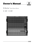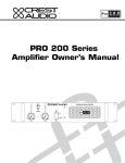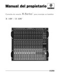
1
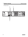
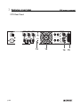
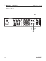
CPX
owner’s manual
S E R I E S
CPX power amplifier
20
20
23
26
16
6
29
(dB)
32
A
PWR
SIG
B
GCLTM
GCLTM SIG
CPX 900
CPX 1500
CPX 2600
23
6
PWR
ON
26
16
29
(dB)
32
CPX 2600
POWER AMPLIFIER
POWER
important precautions
1
Save the carton and packing materials! Should you ever need to ship
the unit, use only the original factory
packing.
Do not run the output of any amplifier channel back into another
channel’s input.
For replacement packaging, call Crest
Audio’s Customer Service Department
directly.
Do not parallel- or series-connect an amplifier output with any
other amplifier output.
2
Read all documentation before
operating your equipment. Retain
all documentation for future reference.
Crest Audio is not responsible for
damage to loudspeakers for any reason.
3
Follow all instructions printed on
unit chassis for proper operation.
4
5
6
7
8
Never hold a power switch or circuit breaker in the on-position, if
it won’t stay there by itself!
Do not use the unit if the electrical power cord is frayed or broken.
The power supply cords should be
routed so that they are not likely to
be walked on or pinched by items
placed upon or against them.
Always operate the unit with the
AC ground wire connected to the
electrical
system
ground.
Precautions should be taken so that
the means of grounding of a piece of
equipment is not defeated.
Damage caused by connection to
improper AC voltage is not covered by any warranty. Mains voltage
must be correct and the same as that
printed on the rear of the unit.
Do not ground any hot (red) terminal.
Never connect a hot (red) output to
ground or to another hot (red) output!
9
Power down and disconnect units
from mains voltage before making
connections.
10
Do not drive the inputs with a
signal level greater than that
required to enable equipment to
reach full output.
Do not connect the inputs or outputs of amplifiers to any other
voltage source: such as a battery,
mains source, or power supply,
regardless of whether the amplifier
is turned on or off.
Connecting amplifier outputs to
oscilloscopes or other test equipment while the amplifier is in
bridged mono mode may damage
both the amplifier and test equipment!
Service Information
Do not remove the cover!
Removing the cover will expose you
to potentially dangerous voltages.
There are no user serviceable parts
inside.
Equipment should be serviced
by qualified service personnel
when:
A. The power supply cord or the plug has
been damaged.
B. The equipment has been exposed to
rain.
C. The equipment does not appear to
operate normally, or exhibits a marked
change in performance.
D. The equipment has been dropped, or
the enclosure damaged.
To obtain service:
contact your nearest Crest Audio
Service Center, Distributor, Dealer,
or Crest Audio at 201.909.8700
USA
Do not spill water or other liquids
into or on the unit, or operate the
unit while standing in liquid.
Do not block fan intake or
exhaust ports.
Do not operate equipment on a
surface or in an environment
which may impede the normal
flow of air around the unit: such
as a bed, rug, weathersheet, carpet, or completely enclosed rack.
If the unit is used in an extremely dusty or smoky environment:
the unit should be periodically
“blown free” of foreign matter.
Do not use the unit near stoves,
heat registers, radiators, or other
heat producing devices.
The power cord of equipment
should be unplugged from the outlet when left unused for a long period of time.
or visit www.crestaudio.com for
additional information.
email: [email protected]
CPX Owner’s manual
1
2
installation
3
features overview
4
introduction
p.3
p.5
unpacking
mounting
cooling and ventilation
powering
maintenance
p.11
front panel
rear panel
contents
application details
p.23
installations
bridged
GCL
5
connections
6
Specifications p.31
wire gauge charts
p.27
input
output
p.32, 33
p. 1
1
p. 2
introduction
CPX owner’s manual
introduction
1
welcome
Congratulations on your purchase of a new CPX Series power amplifier, and
thank you for your confidence in Crest Audio products. You are among the growing number of audio professionals who have made Crest Audio one of the world’s
leading suppliers of professional and commercial/industrial audio systems.
For your safety, please read the Important Precautions section before installing
and operating the amplifier. The Crest Audio CPX Series amplifiers are designed
for high operating efficiency and accurate sonic performance across the full audio
bandwidth, even under stressful conditions.
CPX series amplifiers feature a 2-way crossover and sub-sonic (low-cut) filter for
each channel. Crossover frequencies are fixed at 150 Hz, allowing subwoofers to
be driven at extremely high sound pressure levels, and the filters cut at 40 Hz to
prevent low-end rumble. Using proven technology gained through years of amplifier design, this unit takes advantage of rugged TO-3P output devices mounted
on massive aluminum extrusions and dissipates heat via an extremely quiet and
effective 2-speed fan. CPX amplifiers employ mammoth toroidal power transformers and offer impressive specifications and features not found on similarly
priced competitive units.
These amps are designed to drive a 2-ohm load per channel, thus achieving awesome performance levels into 4 ohms in BRIDGE mode. CPX amplifiers are
ruggedly constructed, rack-mountable pieces of gear with superb patching capability, allowing superior flexibility in application.
Front panel features include calibrated, detented gain (dB) controls and LED indicators for power (PWR), signal presence (SIG), and GCL (Gain Comparator
Limiter) activation on each channel, as well as a rocker mains POWER switch.
The back panel contains an IEC connector for the mains power cord, a mains circuit breaker with reset, and the critical cooling fan opening. This opening should
have an adequate supply of cool air and should never be blocked or restricted.
Also on the back panel are the input and output sections, including an input barrier strip for permanent installations. Each channel input section includes a combo
XLR / ¼" phone jack connector, THRU/LOW out and HIGH out ¼" jacks, and activation switches for the LOW CUT filter and crossover (150 Hz XOVER). Channel
output sections feature dual shock-proof binding posts and 4-conductor Speakon
connectors. An additional 4-conductor Speakon connector allows BRIDGE mode
output.
p. 3
2
p. 4
installation
CPX owner’s manual
installation
what to do with the shipping carton
2
unpacking
proper rack-mounting technique
keeping the amplifier cooled
mounting
routine maintenance practices
cooling and
ventilation
maintenance
p. 5
2 installation
CPX owner’s manual
unpacking
Please inspect the amplifier carefully immediately after unpacking. If
you find any damage, notify your supplier/dealer immediately. Only the
shipper may file a damage claim with the carrier for damage incurred
during shipping. Be sure to save the carton and all packing materials
for the carrier’s inspection.
If the packing materials are in good condition, please save them.
If you ever need to ship the unit anywhere without mounting it in a rack,
you should take advantage of the original factory packing materials in
order to avoid unnecessary damage.
For replacement packaging, call Crest Audio’s
Customer Service
Department directly.
see—service and support
p. 6
installation
2
mounting
All CPX Series amplifiers mount in standard 19-inch racks and occupy two rack
spaces. Use of rear supports is highly recommended in all mobile and touring
sound systems.
CPX Front panel
front
height
3.47" /
88 mm
20
20
23
26
16
6
29
(dB)
32
A
PWR
SIG
B
GCLTM
GCLTM SIG
23
ON
26
16
6
29
PWR
(dB)
CPX 2600
32
POWER AMPLIFIER
POWER
front width 19" / 483mm
CPX rear panel
rear width 17" / 432mm
CAUTION
CHANNEL A INPUT
CHANNEL A
BRIDGE
LOW CUT
TO REDUCE THE RISK OF FIRE OR
ELECTRIC SHOCK DO NOT EXPOSE THIS EQUIPMENT
TO RAIN OR MOISTURE.
AVIS: RISQUE DE CHOC ELECTRIQUE-NE PAS OUVRIR.
150 Hz
X OVER
+
+
-
CHANNEL B
OUTPUT
-
MOUNT IN RACK ONLY - INSTALLER SUR
SUPPORT DE MONTAGE SEULEMENT
GCL TM
OUT ENABLE /
IN DEFEAT
CHANNEL A
A
LOW CUT
BAL. LOW Z
GND
HIGH Z
150 Hz
X OVER
B
-
BRIDGE
THRU
HIGH OUT LOW OUT
+
BRIDGE
OUT STEREO/
IN BRIDGE
-
15
A
M
P
CHANNEL B
WARNING:
+
front
height
3.47" /
88mm
BREAKER
CHANNEL B INPUT
CPX side view
depth16"
p. 7
2 installation
CPX owner’s manual
INSTALLATION
CPX professional power amplifiers are designed for durability in commercial installations and provide the quality performance required in
studio and home applications. They are 2-rack-space units of 16" (406
mm) depth designed to mount in a standard 19" rack. Rear mounting
ears are provided for additional support. The minimum rack depth
required from the mounting surface is 17" (432 mm) to allow adequate
connector clearance.
cooling and ventilation
CPX amplifiers use a forced air cooling system to maintain a low, even
operating temperature.
Air is drawn in by a DC fan on the rear panel, flows through the cooling fins and then exhausts through the front panel vent.
Heatsink temperature is monitored and controls the variable speed
fan. Fan speed increases only as required, keeping fan noise to a minimum.
If the heatsink surpasses it’s maximum allowed temperature, the thermal protection circuit will activate and open the output relays allowing
the amplifier to cool to a safe temperature. Thermal protect activation
only occurs under extreme thermal conditions and is not part of normal operation.
p. 8
Make certain that there
is enough space
around the front and
rear of the amplifier to
allow the heated air to
escape. When mounting in a rack, try to
avoid using doors or
covers on the front and
rear of the enclosure;
the exhaust air must
not be impeded
suggestion
In racks with closed
backs allow at least
one standard-rackspace opening for
every four amps.
installation
2
Basic setup
Rack mount the amplifier in the location where it is to be used, remembering to
allow for adequate access and cooling space. Make all the connections to the
proper INPUT connectors on the desired channel. Select the proper mode configuration (STEREO or BRIDGE). Connect speakers to the proper OUTPUT connectors, reviewing carefully the impedance and phase considerations. With the
POWER switch OFF, connect the IEC cord to the amplifier and then to a suitable
electrical outlet to allow proper current draw. With both channel gain (dB) controls
at their fully counterclockwise (-8) settings, turn the POWER switch to ON, and
slowly raise the gain controls to desired settings. Please carefully review this
manual. It covers all this information in greater detail.
maintenance
CPX amplifiers require no routine maintenance other than checking the cooling
fans to make sure they’re unblocked and working.
If the amplifier is used in an extremely dusty or smoky environment , the unit
should be periodically “ blown free “ ( using compressed air ) of any foreign matter that may have built up inside the unit.
Users will not need to make any adjustments to the amplifier during it’s lifetime.
There are no user-serviceable parts or adjustments that require opening the
amplifier.
p. 9
3
p. 10
features overview
CPX owner’s manual
features overview
location of connectors and controls
3
front panel
Descriptions of connectors and controls
rear panel
p. 11
3 features overview
CPX owner’s manual
CPX Front panel
5
1 2 3 4
20
23
20
26
16
6
29
(dB)
p. 12
32
A
PWR
SIG
B
GCLTM
GCLTM SIG
23
ON
26
16
6
PWR
6
29
(dB)
32
CPX 2600
POWER AMPLIFIER
POWER
features overview
3
front panel
1 Channel Level attenuators
Two input attenuators adjust level for their respective amplifier channels. In
Bridged Mono and Parallel modes, the channel A attenuator controls overall
signal level (see rear panel mode switch description).
2 Power LEDs (PWR)
These indicators illuminate when the AC mains power is being supplied to the
amp and both channels are operational. If either channel experiences fault conditions, exceeds safe operating temperature limits, or if the mains circuit breaker trips; both channel power LEDs will be dark, indicating "shutdown". If the
BRIDGE mode is selected, the PWR indicator on channel B will remain dark as
a positive indication of this mode selection.
3 Signal activity LED’s (sig)
These indicators illuminate when the associated channel output signal level
exceeds 1 VRMS.
4 GCL Active LED’s
These indicators illuminate when GCL compression is taking place in the associated channel. With the GCL ENABLE / DEFEAT switch on the back panel in
the ENABLE position, these LEDs indicate clipping is occurring in the corresponding channel. The Crest GCL limiting system will be covered in greater
detail later in this manual.
5 Fan Outlet Grill
CPX Series amplifiers are cooled by a single rear-mounted fan. Cool air flows
over the heat sink and exhausts through the front grill. Make sure this outlet
remains clear to allow unrestricted airflow.
6 Power switch
This heavy-duty, rocker-type switch turns ON the mains power to the amplifier.
When the mains power is applied, there is a 3-second delay in activation of the
unit. This reduces/eliminates the turn-on transients associated with the system
equipment connected to the amplifier and protects loudspeakers.
p. 13
3 features overview
CPX owner’s manual
CPX Rear Panel
7
CAUTION
CHANNEL A INPUT
CHANNEL A
BRIDGE
LOW CUT
WARNING:
TO REDUCE THE RISK OF FIRE OR
ELECTRIC SHOCK DO NOT EXPOSE THIS EQUIPMENT
TO RAIN OR MOISTURE.
AVIS: RISQUE DE CHOC ELECTRIQUE-NE PAS OUVRIR.
150 Hz
X OVER
+
-
p. 14
+
8
CHANNEL B
OUTPUT
-
MOUNT IN RACK ONLY - INSTALLER SUR
SUPPORT DE MONTAGE SEULEMENT
CHANNEL A
GCL TM
OUT ENABLE /
IN DEFEAT
THRU
HIGH OUT LOW OUT
LOW CUT
BAL. LOW Z
GND
HIGH Z
150 Hz
X OVER
CHANNEL B INPUT
B
-
BRIDGE
A
+
BRIDGE
OUT STEREO/
IN BRIDGE
-
15
A
M
P
CHANNEL B
+
BREAKER
features overview
3
rear panel
7 Circuit breaker
There is one circuit BREAKER on the CPX amplifier. This breaker is provided
to limit current to the associated power transformer, and protect it from overheating and possible destruction due to fault conditions in the unit. The trip current values have been carefully chosen to allow reasonable continuous power
output performance, while still protecting the power transformer. This breaker
should not trip unless there is a fault in the amplifier circuitry that causes excessive mains current draw. However, abnormal conditions such as a short circuit
on either or both channels, or continuous operation at overload or clipping
(especially into 2-ohm loads per channel or 4-ohm bridge load) can cause the
breaker to trip. If this occurs, turn the POWER switch OFF and reset the breaker, after waiting a brief period of time to allow the unit to cool down. Efforts
should be made to correct the cause of the overload if possible. When tripped,
the button on the BREAKER will be outward approximately ¼" and can be
reset by pushing inward and upward. A normal reset button is relatively flat. If
the breaker trips instantly each time you attempt to turn the unit on, it should be
taken to a qualified Crest Service Center for repair.
8 IEC Mains connector
This is a standard IEC power connector. An AC mains cord having the appropriate AC plug and ratings for the intended operating voltage is included in the
carton.
US Domestic AC Mains cord (not pictured)
The mains cord supplied with the unit is a heavy-duty, 3-conductor type with a
conventional 120 VAC plug with ground pin. It should be connected to an independent circuit capable of continuously supporting at least 15 amps. This is
particularly critical for sustained high-power applications. If the outlet used does
not have a ground pin, a suitable grounding adapter should be used and the
third wire grounded properly.
Never break off the ground pin on any equipment. It is provided for your safety.
The use of extension cords should be avoided but, if necessary, always use a
3-wire type with at least a #14 AWG wire size. The use of lighter wire will
severely limit the power capability of this amplifier. Always use a qualified electrician to install any new electrical equipment. To prevent the risk of shock or
fire hazard, always be sure that the amplifier and all associated equipment is
properly grounded.
p. 15
3
features overview
CPX owner’s manual
CPX Rear Panel
11
10
CAUTION
CHANNEL A INPUT
CHANNEL A
BRIDGE
LOW CUT
TO REDUCE THE RISK OF FIRE OR
ELECTRIC SHOCK DO NOT EXPOSE THIS EQUIPMENT
TO RAIN OR MOISTURE.
AVIS: RISQUE DE CHOC ELECTRIQUE-NE PAS OUVRIR.
150 Hz
X OVER
+
+
-
CHANNEL B
OUTPUT
9
p. 16
-
MOUNT IN RACK ONLY - INSTALLER SUR
SUPPORT DE MONTAGE SEULEMENT
CHANNEL A
GCL TM
OUT ENABLE /
IN DEFEAT
A
LOW CUT
BAL. LOW Z
GND
HIGH Z
150 Hz
X OVER
CHANNEL B INPUT
B
-
BRIDGE
THRU
HIGH OUT LOW OUT
+
BRIDGE
OUT STEREO/
IN BRIDGE
-
15
A
M
P
CHANNEL B
WARNING:
+
BREAKER
features overview
3
rear panel
9 Binding post outputs
Shockproof binding post speaker outputs are provided on the CPX amplifier.
For each channel, the outputs are in parallel and the speaker connection
cables can be terminated with banana plugs or stripped wires for use in the
binding post terminals, or can be connected using the Speakon outputs (9). For
sustained high-power applications, either outputs can be used; however, exercise care to assure the correct speaker phasing. The red binding posts are the
signal outputs from each channel, and the black binding posts are chassis
ground. The red binding post should be connected to the positive inputs of the
associated loudspeakers. For BRIDGE mode operation, only the red binding
posts are used and the associated loudspeaker load is connected between the
two red posts.
WARNING…Regardless of what connections are used, the minimum parallel
speaker load should always be limited to 2 ohms per channel or 4 ohms
BRIDGE mode for any application. Operation at loads of 4 ohms per channel,
or 8 ohms BRIDGE mode, is more desirable for sustained operation applications because the amplifier will run much cooler at this loading. Operation
above 4 ohms per channel and even open-circuit conditions can always be
considered safe, but sustained operation at loads below 2 ohms could result in
temporary amplifier shut down due to the thermal limit circuitry.
10 Speakon outputs
CPX amplifiers utilize three 4-conductor Speakon connectors, one for each
channel and one for BRIDGE mode. Please refer to the BRIDGE MODE section of this manual before attempting to use this mode. For each channel
Speakon, the same impedance rules apply as with the binding posts. Internally,
all the Speakons are wired in what is called the "high current" mode, with pins
1+ and 2+ in parallel, and pins 1- and 2- in parallel. For the CHANNEL A and
CHANNEL B Speakons, the respective channel output appears on pins 1+ and
2+. Pins 1- and 2- are chassis ground. For the BRIDGE Speakon, CHANNEL
A appears on pins 1+ and 2+, and CHANNEL B appears on pins 1- and 2-.
Always check the Speakon connector wiring carefully before using.
11 Mode switch
This switch is used to select STEREO or BRIDGE mode operation. It is a conventional push-push type, requiring a small "tool" to activate. The IN position is
BRIDGE mode; the OUT position is STEREO mode. Exercise care when
selecting the BRIDGE mode. Accidental selection of this mode could damage
loudspeakers, particularly in bi-amped systems. Amplifier BRIDGE mode theory will be covered later in this manual.
p. 17
3
features overview
CPX owner’s manual
CPX Rear Panel
CAUTION
CHANNEL A INPUT
CHANNEL A
BRIDGE
LOW CUT
TO REDUCE THE RISK OF FIRE OR
ELECTRIC SHOCK DO NOT EXPOSE THIS EQUIPMENT
TO RAIN OR MOISTURE.
AVIS: RISQUE DE CHOC ELECTRIQUE-NE PAS OUVRIR.
150 Hz
X OVER
BRIDGE
OUT STEREO/
IN BRIDGE
-
+
+
OUTPUT
BAL. LOW Z
GND
HIGH Z
B
150 Hz
X OVER
CHANNEL A
CHANNEL B INPUT
-
12
p. 18
LOW CUT
+
CHANNEL B
GCL TM
OUT ENABLE /
IN DEFEAT
-
THRU
HIGH OUT LOW OUT
BRIDGE
MOUNT IN RACK ONLY - INSTALLER SUR
SUPPORT DE MONTAGE SEULEMENT
A
-
15
A
M
P
CHANNEL B
WARNING:
+
BREAKER
13
14 15
features overview
3
rear panel
12 GCL (Gain Comparator Limiter) switch
This switch is used to enable or defeat the GCL limiter circuitry. It is also a conventional
push-push type, requiring a small "tool" to activate. The IN position is DEFEAT; the OUT
position is ENABLE. Normally, the GCL function should be enabled to minimize the possibility of either or both channels going into clipping or overload. With this feature defeated, a severe overload could cause the mains circuit breaker to trip. The Crest GCL limiting system will be covered in greater detail later in this manual.
13 Fan grill
A 2-speed DC fan supplies cool air to the amplifier. THIS INTAKE SHOULD NEVER BE
BLOCKED! The fan switches to high speed automatically when the unit requires additional cooling. At idle and cool, the fan should be in low speed. The fan should never
stop unless the amplifier is switched OFF or the AC mains power source is interrupted.
14 Combo input connector
The combo connector offers both female XLR and ¼" phone jack balanced inputs for
each channel. The XLR is wired with pin 1 as ground, pin 2 positive input, and pin 3
negative input. The ¼" phone jack is a tip/ring/sleeve (3-conductor) type, with the tip
being positive input, the ring negative input, and the sleeve ground. It is important to
realize that the XLR, ¼" jack, and barrier strip inputs are all in parallel; therefore a balanced input to the associated channel can be accomplished using a male XLR, a 3-conductor phone jack, or bare wires connected to the barrier strip.
As an alternative, the ¼" input can also be used with a regular tip/sleeve (2-conductor)
type plug commonly found on single-conductor shielded patch cords. In this case, the
input becomes unbalanced, with the tip as positive input, and the sleeve ground (the
ring being grounded by the sleeve of the plug). An additional unique feature of this ¼"
input jack is something called a "quasi-balanced" input. The sleeve of this jack is connected to chassis ground through a relatively low-value resistance that is part of a
ground loop elimination circuit. This circuitry will provide hum-free operation when relatively short ¼" cable patches are made to this input from various outputs on this amplifier, or from other equipment that shares the same rack with this amplifier. The quasi-balanced circuitry is "automatic" and virtually "invisible" in normal usage. This feature can
be defeated with a jumper on the barrier strip from the "-" input terminal of that channel
to the ground terminal.
15 Input barrier strip
A barrier strip is provided for input connections using bare wire or spade lug connections. CPX amplifiers employ low-noise, electronically balanced input circuitry. This circuitry offers a very wide dynamic range capable of handling virtually any input signal
level, while providing excellent common mode rejection to minimize hum and reduce
interference. This strip accepts balanced and unbalanced audio signals. The "+" and "-"
terminals are the positive and negative inputs to the respective channels. The GND terminal is the common ground to both channel inputs. For use with an unbalanced
source, connect the "-" input terminal of the channel to ground with a jumper. If the "-"
input is left floating, a 6 dB loss in channel gain will result and the floating input terminal
may pick up outside noise.
p. 19
3
features overview
CPX owner’s manual
CPX Rear Panel
16
CAUTION
CHANNEL A INPUT
CHANNEL A
BRIDGE
LOW CUT
TO REDUCE THE RISK OF FIRE OR
ELECTRIC SHOCK DO NOT EXPOSE THIS EQUIPMENT
TO RAIN OR MOISTURE.
AVIS: RISQUE DE CHOC ELECTRIQUE-NE PAS OUVRIR.
150 Hz
X OVER
+
+
-
CHANNEL B
OUTPUT
-
MOUNT IN RACK ONLY - INSTALLER SUR
SUPPORT DE MONTAGE SEULEMENT
THRU
HIGH OUT LOW OUT
GCL TM
OUT ENABLE /
IN DEFEAT
BAL. LOW Z
GND
HIGH Z
150 Hz
X OVER
CHANNEL A
CHANNEL B INPUT
17
19
18
p. 20
LOW CUT
B
-
BRIDGE
A
+
BRIDGE
OUT STEREO/
IN BRIDGE
-
15
A
M
P
CHANNEL B
WARNING:
+
BREAKER
features overview
3
rear panel
16 Low cut switch
This switch is used to activate the LOW CUT filter for the corresponding channel. It is
again a push-push type switch, requiring a small "tool" to activate. The IN position routes
the input signals through the 40 Hz LOW CUT filter, while the OUT position bypasses
the filter. This filter will cut extremely low frequencies, protecting speakers from the possibility of over-excursion. The filter low-frequency rolloff is 12 dB per octave. The LOW
CUT filter for each channel will function independently of the crossover function to be
discussed next.
17 Crossover switch (150 Hz XOVER)
This switch is used to activate the 150 Hz crossover for the corresponding channel. It is
also a push-push type switch and requires a small "tool" to activate. The CPX offers two
150 Hz crossovers. These are specially designed features that enhance the response of
most loudspeakers in a typical bi-amped application. Rather than just having a flat output curve, these crossovers use special filters to tailor the response and provide a flat
acoustical output. This type of crossover "sounds" more natural than conventional "statevariable" type crossovers.
With the switch IN, the input signals are routed through the crossover, and the low frequencies are automatically sent to the corresponding channel. At the same time, the
high frequencies are sent to the HIGH OUT (19) jack and must then be patched to
INPUT of the other channel of this amplifier or to another amplifier input to complete the
bi-amped system. Additionally, the low frequencies are sent to the THRU/LOW OUT
(18) jack, and can be patched to other amplifier inputs to permit even larger systems.
With the switch OUT the crossover is defeated, and the input signal is routed directly to
the respective power amp channel. The crossover frequency is fixed at 150 Hz and
cannot be changed. The crossover configuration is a 4-pole Linkwitz-Riley approximation.
18 THRU/LOW Out jacks
As per previous crossover discussion, this ¼" jack supplies low-frequency out signals
from the activated crossover for patching to additional power amplifier inputs, providing
added flexibility in larger bi-amped systems. When the crossover function is not activated, this jack converts to a THRU function, where the output of the electronically balanced input circuitry is supplied to this jack. The THRU function provides the means to
patch a full range input signal to the other input of this amplifier (parallel mode), or to
other amp inputs in the same rack. This function allows one balanced mixer feed to be
connected to the amp via the desired balanced input connector (XLR, ¼", Barrier), and
then further distributed locally. Regardless of the crossover switch position, this ¼" jack
provides an unbalanced (tip/sleeve) output to be patched with single conductor shielded
cables.
19 High Out jacks
Again, as per previous crossover discussion, this ¼" jack supplies high frequency out
signals from the activated crossover for patching to this amplifier and/or additional power
amplifier inputs. Unlike the low-frequency crossover output, that is automatically routed
to the associated channel, the high-frequency output signal must be patched to some
suitable input in order to complete the bi-amped system. This ¼" jack also provides an
unbalanced (tip/sleeve) output to be patched with single-conductor shielded cables.
p. 21
4
p. 22
Application details
CPX owner’s manual
Application details
4
Industrial & commercial installations
For commercial and other installations where sustained high power operation is
required, the amplifiers should be mounted in a standard 19" rack. It is not necessary to leave a rack space between each amplifier in the stack since each fan pulls
air in from the rear and exhausts the hot air out the front. However, an adequate
cool air supply must be provided for the amplifier when rack mounted. The internal
fan must have a source of air that is not preheated by other equipment. The amplifier will start up in low speed fan operation and will normally stay at low speed
unless sustained high-power operating levels occur. Then, as temperatures in the
amplifier heat sinks increase, the automatic thermal-sensing circuitry will cause
high-speed operation to occur. Depending upon signal conditions and amp loading,
high-speed fan operation may continue or the fan may cycle continuously between
high and low. This situation is quite normal. If cooling is inadequate, however, the
amplifier thermal-sensing system may cause temporary shut down of the unit, indicated by the PWR LEDs on both channels going dark. Inadequate cooling may be
due to preheated air, reduced air flow resulting from blockage of inlet/outlet ports,
severe amplifier overload, or short circuit conditions. Depending upon the available
cooling air, operation should be restored relatively quickly, and the power LEDs on
both channels will again be illuminated. In any event, action should be taken to correct the cause of the thermal shutdown. If the amplifier is not severely overloaded
or shorted and air flow is normal in and out of the amplifier, then steps should be
taken to provide a cooler environment for all the amplifiers. As a general rule, the
cooler electronic equipment is operated, the longer its useful service life.
In most low to medium-power applications, the amplifier can be mounted in any
configuration. It is desirable that, if at all possible, the power amplifier be located at
the top of an equipment stack. This will prevent possible overheating of sensitive
equipment by the hot air rising from the power amplifier. As a general rule, most
home and studio requirements will never cause high-speed fan operation. Highspeed operation may indicate that you have not taken the necessary steps to provide adequate cooling. Fully closed up in a cabinet, a CPX Series power amplifier
will have severe cooling problems, even at low power levels.
Bridge mode
The Bridge mode on stereo amplifiers is often misunderstood relating to actual
operation and usage. In basic terms, when a 2-channel amplifier is operated in the
Bridge mode, it is converted into a single-channel unit with a power rating equal to
the sum of the power rating for each channel, at a load of twice that of the singlechannel rating. For example, the CPX 1500 is rated at 750 watts RMS per channel
into 2 ohms. The Bridge rating is 1500 watts RMS into 4 ohms (minimum load).
Bridge mode operation is accomplished by placing the MODE switch in the
BRIDGE position, using only the BRIDGE Speakon connector or the red binding
posts for the output, and using the CHANNEL A input. All CHANNEL B input functions are defeated and serve no purpose now. Bridge mode operation can be used
to drive sound distribution systems in very large public address applications.
Another common use for the Bridge mode is in subwoofer applications where very
high power levels are required to reproduce extremely low frequencies with adequate headroom. Such enclosures usually contain 2 or 4 loudspeakers to handle
the power levels involved. For Bridge mode usage, the enclosure impedance must
be 4 or 8 ohms?never below 4 ohms.
p. 23
4
p. 24
Application details
CPX owner’s manual
Application details
4
Industrial & commercial installations
GCL
Crest's patented GCL (Gain Comparator Limiting) circuit enables the sound technician to maximize the performance of the amplifier/speaker combination by preventing the power amplifier from running out of headroom (clipping). This limiting
system is activated by a unique circuit that senses signal conditions that might
overload the amplifier and activates compression (reduces the channel gain)
when clipping is imminent. The threshold of limiter is clipping itself, and no specific
threshold control is used. This technique effectively utilizes every precious watt
available for the power amplifier to reproduce the signal, while at the same time
minimizing clipping and distortion. GCL significantly reduces the potential of loudspeaker degradation and damage, and is the most effective, automatic, hands-off
approach to the problem of power amplifier clipping.
Since CPX series power amplifiers use a circuit breaker for overcurrent protection,
the GCL limiter system plays an even more important role in continuous performance by preventing each channel from clipping and overload. Continuous operation at clipping can cause the circuit breaker to trip, but with the GCL activated,
this problem is minimized. For this reason, the GCL compression system should
always be enabled.
For commercial and other installations where sustained high power operation is
required, the amplifiers should be mounted in a standard 19" rack. It is not necessary to leave a rack space between each amplifier in the stack since each fan
pulls air in from the rear and exhausts the hot air out the front. However, an adequate cool air supply must be provided for the amplifier when rack mounted. The
internal fan must have a source of air that is not preheated by other equipment.
The amplifier will start up in low speed fan operation and will normally stay at low
speed unless sustained high-power operating levels occur. Then, as temperatures
in the amplifier heat sinks increase, the automatic thermal-sensing circuitry will
cause high-speed operation to occur. Depending upon signal conditions and amp
loading, high-speed fan operation may continue or the fan may cycle continuously
between high and low. This situation is quite normal. If cooling is inadequate, however, the amplifier thermal-sensing system may cause temporary shut down of the
unit, indicated by the PWR LEDs on both channels going dark. Inadequate cooling may be due to preheated air, reduced air flow resulting from blockage of
inlet/outlet ports, severe amplifier overload, or short circuit conditions. Depending
upon the available cooling air, operation should be restored relatively quickly, and
the power LEDs on both channels will again be illuminated. In any event, action
should be taken to correct the cause of the thermal shutdown. If the amplifier is
not severely overloaded or shorted and air flow is normal in and out of the amplifier, then steps should be taken to provide a cooler environment for all the amplifiers. As a general rule, the cooler electronic equipment is operated, the longer its
useful service life.
In most low to medium-power applications, the amplifier can be mounted in any
configuration. It is desirable that, if at all possible, the power amplifier be located at
the top of an equipment stack. This will prevent possible overheating of sensitive
equipment by the hot air rising from the power amplifier. As a general rule, most
home and studio requirements will never cause high-speed fan operation. Highspeed operation may indicate that you have not taken the necessary steps to provide adequate cooling. Fully closed up in a cabinet, a CPX Series power amplifier
will have severe cooling problems, even at low power levels.
p. 25
5
p. 26
connections
CPX owner’s manual
connections
5
AMPLIFIER CONFIGURATIONS
BASIC FULL-RANGE STEREO SYSTEM
L & R THRU
Outputs
Right
Full-range
Speaker(s)
Left
Full-range
Speaker(s)
L&R
Inputs
MONO BI-AMPED SYSTEM
1
2
¼” Tip/Sleeve
Patch Cord
Full-range
Speakers
Sub
Speakers
Mono
Input
Push-Push Switch Activation List:
1 - Chan A, Low Cut Switch IN
2 - Chan A, 150 Hz Xover Switch IN
p. 27
5
p. 28
connections
CPX owner’s manual
connections
5
STEREO BI-AMPED SYSTEM
1
2
3
4
¼” Tip/Sleeve
Patch Cords
Right
Full-range
Speaker(s)
Left
Full-range
Speaker(s)
Right Sub
Speaker(s)
L&R
Inputs
Push-Push Switch Activation List:
1 - Chan A Low Cut Switch IN
2 - Chan A 150 Hz Xover Switch IN
3 - Chan B Low Cut Switch IN
4 - Chan B 150 Hz Xover Switch IN
Left Sub
Speaker(s)
BRIDGE CONFIGURATION
2
Sub
Speaker(s)
1
Mono
Input
Push-Push Switch Activation List:
1 - Chan A, Low Cut Switch IN
2 - Mode Switch IN (Bridge)
p. 29
specifications
p. 30
CPX owner’s manual
Specifications
CPX 900
CPX 1500
CPX 2600
450 W RMS/chan
300 W RMS/chan
180 W RMS/chan
750 W RMS/chan
500 W RMS/chan
300 W RMS/chan
1300 W RMS/chan
900 W RMS/chan
540 W RMS/chan
RATED OUTPUT POWER:
Stereo mode (EIA both channels driven)
2 ohms EIA, 1 kHz, 1% THD
4 ohms EIA, 1 kHz, 0.1% THD
8 ohms EIA, 1 kHz, 0.1% THD
Bridge mode, mono
4 ohms EIA, 1 kHz, 1% THD
8 ohms EIA, 1 kHz, 0.1% THD
HUM & NOISE:
Stereo mode, below rated
output power, 4 ohms
900 W RMS
600 W RMS
1500 W RMS
1000 W RMS
2600 W RMS
1800 W RMS
100 dB, unweighted
100 dB, unweighted
100 dB, unweighted
DISTORTION: SMPTE-IM
Less than 0.01%
Less than 0.01%
Less than 0.01%
INPUT SENSITIVITY & IMPEDANCE:
@ rated output power, 4 ohms
Balanced, TRS ¼" phone jack
Balanced, XLR (pin 2 positive)
Overall system gain per channel
0.87 V RMS (-1.2 dBV)
10 K ohms per leg
10 K ohms per leg
40X (+32 dB)
1.12 V RMS (+1dBV)
10 K ohms per leg
10 K ohms per leg
40X (+32 dB)
1.5 V RMS (+3.5 dBV)
10 K ohms per leg
10 K ohms per leg
40X (+32 dB)
DISTORTION: (THD, typical value)
Stereo mode, both channels driven, 4 ohms
20 Hz to 20 kHz, 10 dB below rated power
20 Hz to 2 kHz, at full rated power
Less than 0.03%
Less than 0.03%
Less than 0.03%
Less than 0.03%
Less than 0.03%
Less than 0.03%
FREQUENCY RESPONSE:
Stereo mode, both channels driven
+0, -1 dB @ 1 W RMS, 4 ohms
+0, -3 dB @ rated output, 4 ohms
20 Hz to 20 kHz
5 Hz to 50 kHz
20 Hz to 20 kHz
5 Hz to 50 kHz
20 Hz to 20 kHz
5 Hz to 50 kHz
DAMPING FACTOR: (Typical value)
Stereo mode, both channels driven
8 ohms, 1 kHz
Greater than 300
Greater than 300
Greater than 300
POWER CONSUMPTION:
Stereo mode, both channels driven
@ 1/8 rated output power, 4 ohms
5.0 ARMS @ 120 VAC 7.0 ARMS @ 120 VAC 7.0 ARMS @ 120 VAC
TOPOLOGY:
WEIGHT:
Class AB
40 lbs (18.2 kg)
FEATURE SET:
GCL COMPRESSION
COOLING SYSTEM
LOW CUT FILTER
CROSSOVER
INPUTS
CROSSOVER OUTPUTS
AMPLIFIER OUTPUTS
LED INDICATORS
AMP PROTECTION
LOAD PROTECTION
MAINS VOLTAGES AVAILABLE
DIMENSIONS
Class AB
45 lbs (20.5 kg)
Class H
49 lbs (22.3 kg)
All Models (++ indicates each channel)
Automatic, switchable with LED indicator
Two-speed DC fan, air flow back to front
-3 dB @ 40 Hz, 12 dB per octave
150 Hz, 4-pole Linkwitz-Riley approximation
Electronic balanced; Barrier Strip, XLR, TRS ¼" (6.3 mm)
Low/Thru and High, TS ¼" (6.3 mm)
Speakons for Chan A, Chan B & Bridge; Binding Posts
Red, GCL™/clipping; Yellow, signal; Green, power
Full short circuit, open circuit; over-temp thermal; RF; stable into any load
Turn on/off muting, DC (triac crowbar), low-cut filter
100, 120, 230, 240 VAC, 50-60 Hz
Height: 3.5" (8.9 cm), Width: 19" (48.3 cm), Depth: 15.5" (38.0 cm)
Specifications subject to change without notice
p. 31
wire gauge
CPX owner’s manual
stranded cable length
2
5
meters
meters
10
30
p. 32
wire gauge
power loss
0.3mm2
8 Ohm load
2.9%
4 Ohm load
2 Ohm load
0.5
1.74
3.4
6.7
0.75
1.16
2.3
4.5
1.5
0.58
1.16
2.3
2.5
0.35
0.70
1.39
4.0
0.22
0.44
0.87
0.5mm2
4.3%
8.2%
15.5%
0.75
2.9
5.6
10.8
1.5
1.45
2.9
5.6
2.5
0.87
1.74
3.4
4
0.55
1.09
2.2
6
0.37
0.73
1.45
8.24%
5.5%
28%
0.75
5.6
10.8
19.9
1.5
2.9
5.6
10.8
2.5
1.74
2.9
6.7
4
1.09
1.74
4.3
6
0.73
1.09
2.9
15.5%
0.73%
45%
1.5
8.2
15.5
28
2.5
5.1
9.8
18.2
4
3.2
6.3
12.0
6
2.2
4.3
8.2
10
1.31
2.6
5.1
meters 0.5mm2
meters 0.75mm2
5.6%
10.8%
wire gauge
stranded cable length
5
feet
10
40
80
feet
feet
feet
wire gauge
power loss
18 AWG
8 Ohm load
0.81%
4 Ohm load
2 Ohm load
16
0.51
1.02
2.0
14
0.32
0.64
1.28
12
0.20
0.40
0.80
10
0.128
0.25
0.51
18 AWG
1.61%
3.2%
6.2%
16
1.02
2.0
4.0
14
0.64
1.28
2.5
12
0.40
0.80
1.60
10
0.25
0.51
1.01
18 AWG
6.2%
11.9%
22%
16
4.0
7.7
14.6
14
2.5
5.0
9.6
12
1.60
3.2
6.2
10
1.01
2.0
4.0
8
0.60
1.20
2.4
18 AWG
11.9%
22%
37%
16
7.7
14.6
26
14
5.0
9.6
17.8
12
3.2
6.2
11.8
10
2.0
4.0
7.7
8
1.20
2.4
4.7
1.61%
3.2%
p. 33
http://www.crestaudio.com CPX Owner's Manual Version 1.0 02/18/01