1
TSD402 Installation Manual
System Installation
System Installation
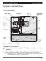
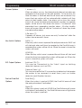
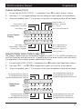
Control Panel layout
Mains Cable
Entry
Cable Entry
PCB
Supports
Loudspeaker
(Under PCB)
Holders for
spare fuses
PCB
Fused
Terminal
Block
(200mA)
PCB
Clips
Transformer
+
Cover
Clips
Battery
2.1 Ah
max.
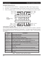
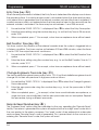
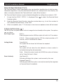
Figure 1
TSD402 Control Panel layout
Installing the Control Panel
+
For your safety, installation of the TSD402 must be conducted in the following
sequence.
1
Remove the screw from the top of the control panel and lift away the front cover.
2
Ensure that there is no battery in the housing, then remove the PCB as follows:
a) Disconnect the AC leads from the transformer and unplug the internal
loudspeaker from the Printed Circuit Board (PCB).
9