1
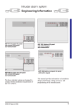
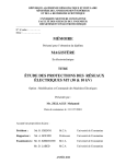
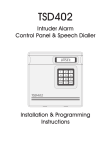
INSTALLATION MANUAL SECURIT 900C CONTROL PANEL CONTENTS WARNINGS STANDARDS WARRANTY STATEMENT PRODUCT DESCRIPTION AVAILABLE PARTS INTENDED USE FACTORY DEFAULTS INSTALLATION MOUNTING PCB LAYOUT WIRING ELECTRICAL SAFETY NOTICE BATTERY SPECIFIATION TELEPHONE CONNECTIONS DETECTOR CIRCUITS NORMALLY CLOSED DOUBLE BALANCED SINGLE END OF LINE SOUNDERS, SPEAKERS & STROBE WIRING INTERNAL SPEAKER AUXILIARY DC DETECTOR POWER TRIGGER OUTPUT DETECTOR RESET SET LATCH ALARM OUTPUT MOUNTING KEYPADS WIRING KEYPADS INITIAL POWER UP ENGINEER MODE ENGINEER RESET PROGRAMMING CONVENTIONS REVIEW PROGRAMMING ZONE PROGRAMMING FULL SET PART SET NIGHT SET SYSTEM OPTIONS EXIT TIME ENTRY TIME BELL CUT-OFF TIME PART SET EXIT WARNING PART SET BELLS & STROBE NIGHT SET BELLS & STROBE ALARM TRIGGER OUTPUT QUICK SET SET INHIBIT MAINS FAIL WARNING SUPPLIMENTARY ENTRY ALARM DELAY ALARM RESET KEYPAD SOFT KEY ALARMS KEYPAD LOCKOUT BELL OUTPUT POLARITY ALARM OUTPUT POLARITY TAMPER ALARM RESET 2 4 4 4 4 4 4 5 6 6 6 6 6 7 7 7 7 7 8 8 8 8 8 8 8 8 9 9 9 9 9 10 10 10 10 10 11 11 11 11 12 12 12 12 12 12 13 13 13 13 13 13 14 14 14 ZONE MODE COMMUNICATIONS PRIMARY TELEPHONE NUMBER SECONDARY TELEPHONE NUMBER ACCOUNT NUMBER USER CODE 8 DURESS ALARM DOWNLOADER TELEPHONE NUMBER DOWNLOADER ID NUMBER AUTO ANSWER RING COUNT ANSWERING MACHINE DEFEAT COMMUNICATIONS FORMAT HANDSHAKE FORMAT DUAL REPORTING DIAL TYPE LINE FAULT INHIBIT SETTING BELL DELAY PUSH TO SET WHEN TO COMMUNICATE LINE FAULT DOWNLOADER OPTIONS ZONE ALARM COUNT LOCKOUT COMMUNICATE REPORT TYPES FIRE ALARMS PA ALARMS ALARMS OPEN / CLOSE DAY TAMPERS ABORT CONFIRMED ALARM LOW BATTERY & MAINS LOSS PERIODIC TEST REPORTS ISOLATE INVERT OPEN / CLOSE DOUBLE KNOCK ZONE ISOLATION ALLOWED COMMUNICATE RESTORE ENTRY DEVIATION PRINT EVENT LOG VIEWING EVENT LOG VIEW EVENT LOG FROM DOWNLOADER RESTORE FACTORY PROGRAMMING DEFAULTS RESTORE DEFAULT CODES SOFTWARE VERSION ADVANCED COMMUNICATIONS TECHNISTORE VERSION CONFIRMED ALARM TIME WINDOW ENGINEER AND USER CODES DOWNLOADER FIRST CONNECTION FAULT FINDING FREQUENTLY ASKED QUESTIONS SPECIFICATIONS CTR21 INTERWORK QUICK PROGRAMMING GUIDE GENERAL WIRING DIAGRAM SOUNDER CONNECTION CHART NOTES ZONE CONFIGURATION CHART 3 14 14 14 14 14 14 15 15 15 15 15 15 15 15 15 16 16 16 16 16 16 17 17 17 17 17 17 17 17 18 18 18 18 18 18 18 19 19 19 19 20 20 20 20 20 20 20 21/22 23 23 24 24 25/27 28 28 28/30 31 WARNINGS Prolonged short circuit of any supply can cause damage to the unit. Take the necessary precautions in not allowing liquids to spill on or into the unit. STANDARDS This unit conforms to EMC directive 89/336/EEC, LVD 73/23/EEC & R&TTE (CTR21). This unit has been tested and has proven to meet all current emission and immunity regulations as set out by the EU. This unit conforms to the requirements of BS4737 part 1 1986 which relates to security control equipment. WARRANTY STATEMENT This product is covered by the IntelliSense warranty in force as of the purchase date. A copy may be obtained from the address at the end of this document. PRODUCT DESCRIPTION The Securit 900C is an 8-zone programmable microprocessor control panel with onboard communicator allowing remote upload and download. There are many options in the programming functions to allow the control panel to be versatile and user friendly. This panel is the ideal choice for residential or light commercial installations where remote communications are needed. AVAILABLE PARTS A selection of spares and extras are available. These are: • Remote Keypad giving full control over the control panel. • Spare PCB for replacement in the event of damage. These can be obtained from your original place of purchase. INTENDED USE This panel must be installed by a competent person. It is designed to be used in residential and smaller commercial applications such as homes, shops, offices etc. 4 FACTORY DEFAULTS User Code 1 (master) User Code 2 - 8 Engineer Code Full Set Exit Time Night Set Exit Time Entry time Sounder Ring Time Bell Trigger Polarity Zone Mode Zone Programming Zone Full Set 1 Final Exit 2 Walkthrough 3 Alarm 4 Alarm 5 Alarm 6 Alarm 7 Alarm 8 Alarm 1234 Disabled 9090 30 Seconds 30 Seconds 30 Seconds 20 Minutes Negative Normally Closed loops Part Set Final Exit Walkthrough Alarm Alarm Alarm Alarm Alarm Alarm Zone Lockout Double Knock Zone Part Set Exit Warning Part Set External Bell Night Set External Bell Alarm Trigger Output Set Inhibit Alarm Reset Tamper Reset Easy Set User 8 as Duress Zone Isolation Communications Alarm Verification time Auto Answer Ring Count Bell Delay Dial Type Supplementary Entry Alarm Delay Entry Deviation Line Fault Line Fault Set Inhibit Restore Technistore Version Verified Alarms 5 Night Set Final Exit Final Exit Alarm Alarm Alarm Alarm Alarm Alarm After 2 alarms None Silent On On Alarm Mains fail only Customer Customer Disabled Disabled Allowed Alarms in all set modes 45 minutes 14 rings None DTMF None Not allowed Enabled Disabled Sent at unset 000 Not enabled INSTALLATION INSTALLATION Locate the control panel out of sight, such as in a hall, under stairs or in a cupboard where connection is easy and the detector zone and mains cables can be concealed. Avoid areas subject to high temperatures or humidity such as next to a boiler, airing cupboard or conservatory. MOUNTING MOUNTING 1. Remove the lid screws and remove lid. 2. Remove the PCB or keypad packaging. 3. Place the panel in the selected position and mark the fixing holes. 4. Mount the panel securely using all three mounting hole positions. 5. Attach the tamper spring and mount the PCB onto the support pillars. 6. Connect the transformer secondary leads to the AC terminals. 7. Connect the battery leads to BATTERY + and -. Observer polarity. PCB LAYOUT WIRING ELECTRICAL SAFETY NOTICE WIRING THE CONTROL PANEL ELECTRICAL SAFETY NOTICE THIS PRODUCT MUST BE EARTHED This Power Supply must be permanently connected to the mains supply in accordance with current IEE wiring regulations. A 3 amp fused spur, installed by a qualified electrician, is strongly recommended. Any fault which could be mains related must be diagnosed and corrected by a qualified electrician to ensure continued safe operation. CAUTION: Under certain circumstances the transformer metalwork can reach 70°C. This is normal and within prescribed limits. 6 BATTERY SPECIFICATION BATTERY SPECIFICATION Maximum battery size is12 V 7.0 Ah. The panel requires a standby battery to be fitted to provide power in the event of mains failure. A valve regulated lead acid battery must be used. Observe the battery polarity. Take great care to connect correctly. TELEPHONE CONNECTIONS TELEPHONE CONNECTIONS The telephone connections, A & B on TB5, must be hard-wired to the incoming telephone line. If the master socket is the NTE5/CTE5, the connection can be carried out by the installation engineer otherwise the network operator must make the connection. It must NOT be installed as an extension to a payphone. The panel is approved to EEC 98/482/EEC (R&TTE Directive, CTR21-see Page 23 for a list of countries) for single terminal connection to the Public Switched Telephone Network (PSTN) for • Auto dialling • Auto Answer • Modem Communications • Auto Clearing • Multiple Repeat attempts • Series Connections • Operation with Call Process Monitoring (CPM) tone recognition DETECTOR CIRCUITS DETECTOR CIRCUITS Normally Closed Double Balanced EOL Single End-of-Line Connections for up to eight alarm circuits. Normally closed detection devices must be used. The Zones may be programmed for normally closed loop, double balanced or single End-of-Line resistor modes. Programmed as Normally Closed (Factory default) Wire a shorting link across any unused zones. One or more devices may be connected to each alarm circuit. These should be connected in a series configuration. All zone tampers should be wired in series and connected to the Zone Tamp terminals. NORMALLY CLOSED Programmed as Double Balanced End-of-Line DOUBLE Wire a 1kΩ resistor across any unused zones. Only one device BALANCED should be connected to each alarm circuit. Wire the zone and tamper connections in series with a 1kΩ resistor, fit a second 1kΩ resistor across the alarm contact. All other normally closed tampers should wired in series and be connected to the Zone Tamp terminals. 7 SINGLE END OF LINE Programmed as Single End-of-Line Wire a 1kΩ resistor across any unused zones. Only one device should be connected to each alarm circuit. Wire the zone in series with a 1kΩ resistor fitted within the detector. All zone tampers should be wired in series and connected to the Zone Tamp terminals. SOUNDERS, SPEAKERS & STROBES INTERNAL SOUNDERS, SPEAKERS & STROBE WIRING This shows the connection for external sounder and strobe. Please note default sounder trigger is applied negative, (negative ring.). BELL + Sounder hold off/strobe positive supply BELL – Sounder switched negative trigger STRB Strobe switched negative trigger BTMP – R Sounder tamper return (negative) BTMP – Sounder hold off supply & sounder tamper feed (negative) INTERNAL SPEAKER A 16 Ω (ohm) speaker may be fitted between the AUX + & LS terminals. If two speakers are required, these should be wired in series. AUXILIARY DC DETECTOR POWER AUX DC - DETECTOR POWER The auxiliary power is provided from connections marked AUX. This is to provide the 12 V supply for detectors e.g. movement or glassbreak detectors. The auxiliary power output is rated at 500 mA max. (12 VDC nominal). TRIGGER OUTPUT TRIGGER OUTPUT (TRIG) This is a multifunction output and can be programmed using Menu 47. DETECTOR RESET OPTION 1 DETECTOR RESET (Menu 47-1) Some detectors require the removal of power to reset (e.g. Viper Plus® or smoke detectors). The TRIG terminal can be programmed to be used as an 'ID' output using option 4-7-1. The TRIG terminal should then be used as the negative supply for these devices. The positive supply should be taken from the AUX +. SET LATCH OPTION 2 SET LATCH (Menu 47-2) If latching detectors are used the 'TRIG' should be connected to the appropriate SET or LATCH terminal in your detector connection. It is normally high (12 V) going low (0 V) when set, going high in alarm or when the entry sequence starts. See glossary for explanation. ALARM OUTPUT OPTION 3 ALARM OUTPUT (menu 47-3) This option sets the output normally high (12 V), going low in Alarm, Panic or Fire Alarm. 8 MOUNTING A REMOTE KEYPADS 1. Choose the keypad location and then mark the holes for mounting. 2. Make sure the cable is run through the backbox. 3. Screw the backbox in the selected position making sure it is not twisted. WIRING REMOTE KEYPADS Use 4-core cable for connection of all remote keypads. Connect the cable, making sure each wire goes to a like named terminal in the panel. KPD goes to KPAD, + to AUX + and - to AUX -. Tamper is signalled through the data bus so no separate connection is required. MOUNTING REMOTE KEYPADS WIRING REMOTE KEYPADS Individual keypads do not need to be identified to the system. If more than one remote keypad is used it can be either wired back the control panel or daisy chained from another keypad. All connections are in parallel. INITIAL POWER UP Prior to the full wiring of the panel we recommend the following installation stages. The lid should remain off the main control panel. Do NOT connect the battery yet. INITIAL POWER UP 1. Connect the keypad, wire and switch on the mains supply. The keypad buzzer will start. This denotes a tamper alarm. 2. Enter 1 2 3 4. This will silence the keypad buzzer. This has now acknowledged and cancelled the alarm. However, because the panel lid is removed, the main tamper loop is open and the keypad will indicate the tamper. This is normal. 3. Close the panel lid, enter 1 2 3 4, check the tamper LED clears. 4. Power down and complete the wiring of the control panel. NEVER wire the control panel live. 5. Power back up, enter 1 2 3 4 to cancel the alarm and enter engineer mode by entering 9 0 9 0 # *. The panel is now ready for programming. ENGINEER MODE To enter engineer mode, enter the engineer code and then press the # and * keys. The mains light will flash and the keypad will bleep twice to signify the panel has entered engineer mode. Entering engineer mode will abort any communications that may be in progress. ENTER & EXIT ENGINEER MODE To exit engineer mode, close ALL tamper circuits and enter the # and * keys. ENGINEER RESET To perform an engineer reset, enter the engineer code. There is no need to enter engineer programme mode. 9 ENGINEER RESET PROGRAMMING CONVENTIONS PROGRAMMING CONVENTIONS The following conventions are used in the Menu tables: (z) Zone Number – enter key for required zone number. (o) Option Number – enter key for required option number. Two bleeps will follow a successful data entry. REVIEWING PROGRAMMING The currently programmed setting in menu options can easily be reviewed. With the exception of menu 6, enter the first menu number followed by 00. The display will sequence through the current setting for each option selected in the group eg. to view night set zones enter 3 0 0. The display will step through the setting starting at zone 1 and ending with zone 8. A bleep will be heard each time the display steps. To review menu 6 (the communications options) enter 6 0 followed by the sub option number. eg. to review the primary telephone number enter 6 0 1. The display will step through each digit of the programmed number. A bleep will be heard each time the display steps. The display will show numbers 1 through 8, with ‘day’ corresponding to 0 and ‘Tamper’ corresponding to 9. ZONE PROGRAMMING ZONE PROGRAMMING Any zone may have independent options programmed for Full, Part & Night set. FULL SET FULL SET ZONE PROGRAMMING MENU 1 Enter 1-(z)-(o). Enter 1 followed by the key corresponding to the Option Number required from the table below: Enter 0 Not Used Enter 1 Final Exit Enter 2 Keyswitch Enter 3 Full Alarm Enter 4 Walkthrough Enter 5 Tamper (24 hr) Enter 6 Silent PA Enter 7 Audible PA Enter 8 Exit Terminator Enter 9 Fire PART SET PART SET ZONE PROGRAMMING MENU 2 Enter 2-(z)-(o). Enter 2 followed by the key corresponding to the Option Number required from the table below: Enter 0 Not Used Enter 1 Final Exit Enter 2 Keyswitch Enter 3 Full Alarm Enter 4 Walkthrough Enter 5 Tamper (24 hr) Enter 6 Silent PA Enter 7 Audible PA Enter 8 Exit Terminator Enter 9 Fire 10 NIGHT SET ZONE PROGRAMMING MENU 3 Enter 3-(z)-(o). Enter 3 followed by the key corresponding to the Option Number required from the table below: Enter 0 Not Used Enter 1 Final Exit Enter 2 Keyswitch Enter 3 Full Alarm Enter 4 Walkthrough Enter 5 Tamper (24 hr) Enter 6 Silent PA Enter 7 Audible PA Enter 8 Exit Terminator Enter 9 Fire NIGHT SET SYSTEM OPTIONS SYSTEM OPTIONS EXIT TIME MENU 41 Enter 41-(o). Enter 4 - 1 followed by the key corresponding to the Option Number required from the table below: Enter 0 Final contact, door closure setting Enter 1 10 seconds Enter 2 20 seconds Enter 3 30 seconds (Default) Enter 4 40 seconds Enter 5 50 seconds Enter 6 60 seconds Enter 7 70 seconds Enter 8 80 seconds Enter 9 90 seconds EXIT TIME ENTRY TIME MENU 42 Enter 42-(o). Enter 4 - 2 followed by the key corresponding to the Option Number required from the table below: Enter 1 10 seconds Enter 2 20 seconds Enter 3 30 seconds (Default) Enter 4 40 seconds Enter 5 50 seconds Enter 6 60 seconds Enter 7 70 seconds Enter 8 80 seconds Enter 9 90 seconds ENTRY TIME 11 BELL CUT-OFF TIME BELL CUT-OFF TIME MENU 43 Enter 43-(o). Enter 4 - 3 followed by the key corresponding to the Option Number required from the table below: Enter 1 1 Minute Enter 2 2 Minutes Enter 3 3 Minutes Enter 4 4 Minutes Enter 5 5 Minutes Enter 6 10 Minutes Enter 7 15 Minutes Enter 8 20 Minutes (Default) Enter 9 30 Minutes PART SET EXIT WARNING PART SET EXIT WARNING SOUNDER MENU 44 Enter 44-(o). Enter 4 - 4 followed by the key corresponding to the Option Number required from the table below: Enter 0 Fault & comfort tones only (Default) Enter 1 Keypad buzzer only Enter 2 Keypad buzzer and sounder Note. Night set will always be silent i.e. no exit and fault tones heard. With option 2 selected, night set comfort and end of exit time fault tones will be through both the keypad and internal speaker. PART SET BELLS & STROBE EXTERNAL BELLS & STROBE IN PART SET MENU 45 Enter 45-(o). Enter 4 - 5 followed by the key corresponding to the Option Number required from the table below: Enter 0 Off Enter 1 On (Default) NIGHT SET BELLS & STROBE EXTERNAL BELLS & STROBE IN NIGHT SET MENU 46 Enter 46-(o). Enter 4 - 6 followed by the key corresponding to the Option Number required from the table below: Enter 0 Off Enter 1 On (Default) ALARM TRIGGER OUTPUT ALARM TRIGGER OUTPUT MENU 47 Enter 47-(o). Enter 4 - 7 followed by the key corresponding to the Option Number required from the table below: Enter 0 0 V Detector reset Enter 1 Set Latch positive Enter 2 Alarm (Default) QUICK SET QUICK SET MENU 48 Enter 48-(o). Enter 4 - 8 followed by the key corresponding to the Option Number required from the table below: Enter 0 Off (Default) Enter 1 On When enabled, users set the system by pressing the # key and 1 (to Full Set), 2 (to Part Set), or 3 (to Night Set). A valid user code is still required to unset the system. 12 SET INHIBIT MENU 49 Enter 49-(o). Enter 4 - 9 followed by the key corresponding to the Option Number required from the table below: Enter 0 Mains Fail (Default) Enter 1 Low battery Enter 2 Mains fail and Low battery SET INHIBIT MAINS FAIL WARNING MENU 51 Enter 51-(o). Enter 5 - 1 followed by the key corresponding to the Option Number required from the table below: Enter 0 Off (Default) Enter 1 Audible MAINS FAIL WARNING SUPPLIMENTARY ENTRY ALARM DELAY MENU 52 Enter 52-(o). Enter 5 - 2 followed by the key corresponding to the Option Number required from the table below: Enter 0 Off (Default) Enter 1 30 second full alarm & comms delay on (internal sounders only). SUPPLIMENTARY ENTRY ALARM DELAY ALARM RESET MODE MENU 53 Enter 53-(o). Enter 5 - 3 followed by the key corresponding to the Option Number required from the table below: Enter 0 Customer (Default) Enter 1 Engineer Enter 2 Technistore Enter 3 Technistore & Engineer ALARM RESET MODE KEYPAD SOFT KEY ALARMS MENU 54 Enter 54-(o). Enter 5 - 4 followed by the key corresponding to the Option Number required from the table below: Enter 0 Off (Default) Enter 1 On KEYPAD SOFT KEY ALARMS Keys must be held down together for two seconds for activation. Panic Assistance Fire Press and # together. All LEDs (PA) illuminate and a constant tone emits. Press 4 and 6 together. Keypad displays scrolling LEDs with fast pulse tone. Press 7 and 9 together. Keypad displays scrolling LEDs with slow pulse tone. KEYPAD LOCKOUT MENU 55 Enter 55-(o). Enter 5 - 5 followed by the key corresponding to the Option Number required from the table below. Keypad lockout occurs after 20 incorrect keypresses and lasts for 10 minutes. No codes are accepted during the lockout time. Enter 0 Enter 1 Off (Default) On 13 KEYPAD LOCKOUT BELL OUTPUT POLARITY BELL OUTPUT POLARITY MENU 56 Enter 56-(o). Enter 5 - 6 followed by the key corresponding to the Option Number required from the table below: Enter 0 Negative applied (Default) Enter 1 Negative removed ALARM OUTPUT POLARITY ALARM OUTPUT POLARITY MENU 57 Enter 57-(o). Enter 5 - 7 followed by the key corresponding to the Option Number required from the table below: Enter 0 Negative applied (Default) Enter 1 Negative removed TAMPER ALARM RESET TAMPER ALARM RESET MENU 58 Enter 58-(o). Enter 5 - 8 followed by the key corresponding to the Option Number required from the table below: Enter 0 Customer (Default) Enter 1 Engineer Enter 2 Technistore Enter 3 Technistore & Engineer COMMS ZONE MODE ZONE MODE MENU 59 Enter 59-(o). Enter 5 - 9 followed by the key corresponding to the Option Number required from the table below: Enter 0 Normally closed loops (Default) Enter 1 Double balanced EOL Enter 2 Single EOL COMMUNICATIONS PRIMARY TELEPHONE NUMBER PRIMARY TELEPHONE NUMBER MENU 61 Enter 61 followed by the telephone number. Up to 20 digits are allowed. End entry by pressing *. Enter # at any position to give a 2 second pause. SECONDARY TELEPHONE NUMBER SECONDARY TELEPHONE NUMBER MENU 62 Enter 62 followed by the telephone number. Up to 20 digits are allowed. End entry by pressing *. Enter # at any position to give a 2 second pause. ACCOUNT NUMBER ACCOUNT NUMBER MENU 63 Enter 63 followed by the account number. The entry must be between 4 and 6 digits. End entry by pressing *. USER CODE 8 DURESS ALARM USER CODE 8 DURESS ALARM MENU 64 Enter 64-(o). Enter 6 - 4 followed by the key corresponding to the Option Number required from the table below: Enter 0 Off (Default) Enter 1 On 14 DOWNLOADER TELEPHONE NUMBER MENU 65 Enter 65 followed by the telephone number. Up to 20 digits are allowed. End entry by pressing *. Enter # at any position to give a 2 second pause. DOWNLOADER TELEPHONE NUMBER DOWNLOADER ID NUMBER MENU 66 Enter 66 Followed by an 8 digit ID number corresponding to the ID number entered into the downloader software. Defaults to 99999999. DOWNLOADER ID NUMBER AUTO ANSWER RING COUNT MENU 67 Enter 67-(o). Enter 6 - 7 followed by a two digit number for ring count required between 00 and 15. Default setting is answer after 14 rings. Enter 00 Never answer Enter 15 Answering machine defeat AUTO ANSWER RING COUNT ANSWERING MACHINE DEFEAT This is used to download to the panel when it is on a line shared by a fax or answering machine. To connect, dial in with the downloader, let the phone ring once only. Then hang up the call with the downloader, the answer machine or fax will not respond to the call. The panel detects the single ring and hangs-up, then goes into immediate answer mode for 30 seconds to allow it to respond to the downloader’s repeat call. ANSWERING MACHINE DEFEAT COMMUNICATOR FORMAT MENU 68 Enter 68-(o). Enter 6 - 8 followed by the key corresponding to the Option Number required from the table below: Enter 0 Communicator off (Default) Enter 1 High speed Enter 2 Contact ID COMMS FORMAT HANDSHAKE FORMAT MENU 69 Enter 69-(o). Enter 6 - 9 followed by the key corresponding to the Option Number required from the table below: Enter 0 UK (Default) Enter 1 Belgium Enter 2 Paris HANDSHAKE FORMAT NOTE: This option must remain set as default to operate correctly within the UK. DUAL REPORTING MENU 71 Enter 71-(o). Enter 7 - 1 followed by the key corresponding to the Option Number required from the table below: Enter 0 Off (Default) Enter 1 On DUAL REPORTING NOTE: If dual reporting is selected, a secondary telephone number must be programmed into menu 62. DIAL TYPE MENU 72 Enter 72-(o). Enter 7 - 2 followed by the key corresponding to the Option Number required from the table below: Enter 0 Pulse Enter 1 DTMF (Default) 15 DIAL TYPE LINE FAULT LINE FAULT INHIBIT SETTING MENU 73 INHIBIT SETTING Enter 73-(o). Enter 7 - 3 followed by the key corresponding to the Option Number required from the table below: Enter 0 No (Default) Enter 1 Yes, inhibit setting with phone line fault BELL DELAY BELL DELAY BELL DELAY MENU 74 Enter 74-(o). Enter 7 - 4 followed by the key corresponding to the Option Number required from the table below: Enter 0 No (Default) Enter 1 Yes, 10 minute bell/sounder delay on alarm PUSH TO SET PUSH TO SET MENU 75 Enter 75-(o). Enter 7 - 5 followed by the key corresponding to the Option Number required from the table below: Enter 0 No timed or contact set (Default) Enter 1 Yes, Full set only Enter 2 Yes, Full & Part set Enter 3 Yes, Full & Night set Enter 4 Yes, All set modes NOTE: Push to Set on full set is overridden if final contact/Door setting is selected in Menu 41 (option 0) WHEN TO COMMUNICATE WHEN TO COMMUNICATE MENU 76 Enter 76-(o). Enter 7 - 6 followed by the key corresponding to the Option Number required from the table below: Enter 1 Full set only Enter 2 Full & Part set Enter 3 Full & Night set Enter 4 All set modes (Default) LINE FAULT LINE FAULT MENU 77 Enter 77-(o). Enter 7 - 7 followed by the key corresponding to the Option Number required from the table below: Enter 0 Disabled Enter 1 Enabled (Default) DOWNLOADER OPTIONS DOWNLOADER OPTIONS MENU 78 Enter 78-(o). Enter 7 - 8 followed by the key corresponding to the Option Number required from the table below: Enter 0 Full access allowed Enter 1 No access when set (Default) Enter 2 Prevent unsetting COUNT LOCKOUT ZONE ALARM COUNT LOCKOUT MENU 79 Enter 79-(o). Enter 7 - 9 followed by the key corresponding to the Option Number required from the table below: Enter 0 Lockout after 2 alarms (Default) Enter 1 Lockout after alarm ZONE ALARM 16 COMMUMICATIONS REPORTING TYPES COMMUNICATE FIRE ALARMS MENU 81 Enter 81-(o). Enter 8 - 1 followed by the key corresponding to the Option Number required from the table below: Enter 0 No (Default) Enter 1 Yes COMMS REPORTING TYPES FIRE ALARMS COMMUNICATE PA ALARMS MENU 82 Enter 82-(o). Enter 8 - 2 followed by the key corresponding to the Option Number required from the table below: Enter 0 No (Default) Enter 1 Yes PA ALARMS COMMUNICATE ALARMS MENU 83 Enter 83-(o). Enter 8 - 3 followed by the key corresponding to the Option Number required from the table below: Enter 0 No Enter 1 Yes (Default) ALARMS COMMUNICATE OPEN / CLOSE MENU 84 Enter 84-(o). Enter 8 - 4 followed by the key corresponding to the Option Number required from the table below: Enter 0 No (Default) Enter 1 Yes OPEN / CLOSE COMMUNICATE DAY TAMPERS MENU 85 Enter 85-(o). Enter 8 - 5 followed by the key corresponding to the Option Number required from the table below: Enter 0 No (Default) Enter 1 Yes DAY TAMPERS COMMUNICATE ABORTS MENU 86 Enter 86-(o). Enter 8 - 6 followed by the key corresponding to the Option Number required from the table below: Enter 0 No (Default) Enter 1 Yes ABORTS COMMUNICATE CONFIRMED ALARM MENU 87 Enter 87-(o). Enter 8 - 7 followed by the key corresponding to the Option Number required from the table below: Enter 0 No (Default) Enter 1 Yes CONFIRMED ALARM Allows the signalling of alarm confirmation as code 1 on channel 8. The confirmed alarm time window is programmable in menu 02. This defaults to 45 minutes between two separate zone activations. 17 LOW BATTERY & MAINS LOSS COMMUNICATE LOW BATTERY & MAINS LOSS MENU 88 Enter 88-(o). Enter 8 - 8 followed by the key corresponding to the Option Number required from the table below: Enter 0 No (Default) Enter 1 Yes PERIODIC TEST REPORT COMMUNICATE PERIODIC TEST REPORT MENU 89 Enter 89-(o). Enter 8 - 9 followed by the key corresponding to the Option Number required from the table below: Enter 0 No (Default) Enter 1 Every 24 hrs Enter 2 Every 7 days Enter 3 Every 31 days ISOLATE COMMUNICATE ISOLATE MENU 91 Enter 91-(o). Enter 9 - 1 followed by the key corresponding to the Option Number required from the table below: Enter 0 No (Default) Enter 1 Yes INVERT OPEN / CLOSE REPORT INVERT OPEN / CLOSE REPORT MENU 92 Enter 92-(o). Enter 9 - 2 followed by the key corresponding to the Option Number required from the table below: Enter 0 No (Default) Enter 1 Yes DOUBLE KNOCK ZONE DOUBLE KNOCK ZONE MENU 93 Enter 93-(z). Enter 9 - 3 followed by the key corresponding to the Zone Number required. Only one zone may be selected as double knock. Enter 0 None selected (Default) Enter 1-8 Zone selected This option allows one zone to be programmed as a Double Knock zone. The control panel will only acknowledge the Double Knock zone if it is activated twice within five minutes, or once for more than ten seconds continuous activation. ISOLATION ALLOWED ISOLATION ALLOWED MENU 94 Enter 94-(o). Enter 9 - 4 followed by the key corresponding to the Option Number required from the table below: Enter 0 No Enter 1 Yes (Default) COMMUNICATE COMMUNICATE RESTORE RESTORE COMMUNICATE RESTORE MENU 95 Enter 95-(o). Enter 9 - 5 followed by the key corresponding to the Option Number required from the table below: Enter 0 At unset Enter 1 At reset (Default) 18 ENTRY DEVIATION MENU 96 Enter 96-(o). Enter 9 - 6 followed by the key corresponding to the Option Number required from the table below: Enter 0 Disabled (Default) Enter 1 Enabled ENTRY DEVIATION PRINT EVENT LOG MENU 97 Enter 97-(o). Enter 9 - 7 followed by the key corresponding to the Option Number required from the table below: Enter 0 Disabled (Default) Enter 1 Print log PRINT EVENT LOG The full 250 Event time and date stamped Log can be printed in full by a serial printer connected to the AUX supply and loudspeaker terminal via an adapter (Part No. 2011-096 ). Connect to the panel as follows. The data format is • Baud Rate 1200 • Parity None • Data Bits • Stop Bits 8 2 When a printer is connected, the print is started by entering 9-7-1 then exiting Programming Mode by pressing # and *. The complete log will be printed. The log will not print again until this operation is repeated. Disconnect the printer, replace the control panel lid and reset the system. VIEWING THE EVENT LOG AT THE KEYPAD VIEWING EVENT LOG To view the 16 Event Log, Enter a valid User Code and press 0. The most recently activated zone LED lights and the keypad will beep once. The system will scroll through the history of the zone activations. If a zone has been activated two or more times in succession the zone LED will display and the keypad will beep for each activation. Softkey alarms are indicated by all of the Zone LEDs displaying. The keypad will beep twice in rapid succession at the end of the Log display. The time and date stamp information will not be shown. The * key can be used to exit the log at any time. VIEWING THE EVENT LOG FROM DOWNLOADER The IntelliSense Downloader software allows the 250 Event Log of the panel to be viewed. See the downloader manual for more information. 19 VIEWING EVENT LOG FROM DOWNLOADER RESTORE FACTORY DEFAULTS RESTORE FACTORY PROGRAMMING DEFAULTS MENU 98 Enter 98-1 twice within 5 seconds. RESTORE CODE DEFAULTS RESTORE CODE DEFAULTS To restore the engineer and master user code, disconnect the battery and remove mains power. Re-apply power and within 5 seconds hold the * and # keys down together until two beeps are heard. The engineer code will be restored to 9090 and the master code to 1234. All other user codes will remain unchanged. SOFTWARE VERSION SOFTWARE VERSION MENU 99 Entering 99-1 will display the software version. A sequence of three LEDs will light on the keypad indicating the version number. ADVANCED COMMS ADVANCED COMMUNICATIONS TECHNISTORE VERSION TECHNISTORE VERSION MENU 01 Enter 01 then enter the Technistore three digit version number given by the Central Station (Alarm Receiving Centre, ARC). This defaults to 000. CONFIRMED ALARM TIME WINDOW CONFIRMED ALARM TIME WINDOW MENU 02 Enter 02-(o). Enter 0 - 2 followed by the key corresponding to the Option Number required from the table below: Enter 0 45 minutes (Default) Enter 1 10 minutes Enter 2 20 minutes Enter 3 30 minutes ENGINEER AND USER CODE CHANGE ENGINEER AND USER CODE CHANGE The system has 8 user codes. The default codes are Engineer code 9090 User 1 code 1234. To change the Engineer code, enter your existing code then press 8 0, followed by your new 4-digit code the keypad will give two beeps. If the panel does not accept your code then there may be a conflict with another user code. The panel will abort the code change and retain the old code. Three beeps will be heard from the keypad. Try again with a different code. The other users are changed in the same way using existing code, 8 user number, new code. Code access levels and numbers • User 0 is the Engineer • User 1 is the Master user and can alter all user codes • Other Users 2 - 7 can only alter their own code • All codes have the same access authority • Code 8 is reserved for Duress 20 DOWNLOADER - FIRST CONNECTION To make a first contact from the downloader to the panel. The panel requires the following options programmed before a connection from the downloader can be made. The panel must be in “Day Mode” to enable a connection. DOWNLOADER FIRST CONNECTION At the Panel 1. Enter engineer mode by entering 9090 # *, The power LED will flash. 2. If the control panel programming has not been completed, restore the panel defaults by entering 981 followed by 981 again. 3. Enter the # and * keys to exit programming mode. At the Downloader 1. Create a new site (menu “Site” then “New Site”) program the required panel data. 2. Double click on the site to select. 3. Click on “Panel” then “Communications” 4. Click “Mode” then “first contact” 5. In the mode dropdown box select “Dial Site” 6. Click on the Red telephone icon to start the call. If programmed correctly, the panel will answer the downloader after the number of rings programmed into menu 67 When testing, remember that both the panel and downloader need to be connected to separate telephone lines. PANEL END - FIRST CONNECTION To make a first contact from the panel to the downloader. The panel requires the following options programmed before a connection with the downloader can be made. The panel must be in “Day Mode” to enable a connection. At the Downloader 1. Create a new site (menu “Site” then “New Site”) program the required panel data. 2. Double click on the site to select. 3. Click on “Panel” then “Communications” 4. Click “Mode” then “first contact” 5. In the mode dropdown box select “Waiting for call” 21 PANEL END FIRST CONNECTION PANEL END FIRST CONNECTION At the Panel 1. Enter engineer mode by entering 9090 # *, The power LED will flash. 2. If the control panel programming has not been completed, restore the panel defaults by entering 981 followed by 981 again. 3. Enter 6 5 followed by the Downloader Telephone Number. (Menu 6-5 Downloader Telephone Number). Up to 20 digits are allowed. End entry by pressing * 4. Enter the # and * keys to exit programming mode. 5. Ensure the downloader is waiting for a call (see At the Downloader above). 6. Enter 9090 # 9, the panel will call then call the downloader and establish the call. If programmed correctly, the panel will start the call to the downloader. When testing, remember that both the panel and downloader need to be connected to separate telephone lines. 22 FAULT FINDING A selection of common problems and solutions are listed below. Problem Cause Answer Check 24 hr tamper, sounder Tamper will not clear Tamper loop open. tamper and all devices for an with lid on. open tamper loop. Be sure to HOLD * & # until the Not holding * & # long PA will not work on the alarm activates. enough or option not keypad. Enable option 5-4. enabled. Mains light not on. No mains. Check fuse & mains supply. Battery fuse blown or Connect battery and check 1A Battery not taking over battery not connected or battery fuse. Fit new battery. after mains fail. flat battery. Remote keypad not Incorrect wiring. Check wiring. responding. Make sure the devices are wired Zones failing to activate. Incorrect wiring. in series NOT parallel. Seeing an alarm zone Make sure all zones on entry Zone activates during on entry or deviating route are programmed with entry. from entry route. walkthrough. Do not deviate. Zone activates even in Programmed to PA or Reprogram the zone to be an day mode. FIRE. alarm zone or similar. If you are still experiencing problems, then contact our technical helpline with information at hand regarding your installation. If your problem stems from wiring, you may be required to write down wiring instructions so have a pen and paper at hand. Frequently Asked Questions Question Can two bellboxes be used on the system? Can a ‘sound bomb’ be installed? How many PIRs can be connected to a zone? Can the engineer set the panel without the need of a user code? What happens if the zone is still in fault when the bell cuts off? Will there be any further alarms? Answer Yes, make sure tampers are in series. Be sure not to exceed maximum current rating. Yes, connect between AUX+ and S-. Be sure not to exceed maximum current rating. It is best practice to limit the number of detectors per zone. However up-to 5 may be fitted. Zone resistance should not exceed 50 ohms. Yes, if the engineer code is entered the panel will start the set. The engineer code will also unset if the panel was set using the engineer code, it will not unset if a user set the panel. The panel will re-arm. Any zone in fault will be temporally isolated and will re-arm when the fault clears. Any further alarm activation will trigger the bells again for the selected time. If any zone activates three times in succession it will be isolated. Alarms can occur from other zones. 23 SPECIFICATIONS Mains Supply Voltage PSU Output Voltage Maximum Output Current AUX. Current Panel Quiescent Current 230 V AC Nominal 13.8 V Nominal 1 A (total) 500 mA Max. 30 mA Mains Fuse Battery Fuse AUX Fuse Speaker/Strobe 2 A (20 mm) Ceramic HRC 1 A (20 mm) Anti-surge 500 mA (20 mm) Anti-Surge 500 mA (20 mm) Anti-Surge Normal operating temperature Humidity Dimensions Control Panel Weight Standby Battery Standby Time (load dependent) 0°C to 40°C 10 to 90% R.H. non-condensing 263 mm (W) 223 mm (H) 82 mm (D) 2.7 kg Excluding Battery 12 V 7.0 Ahr Rechargeable Lead Acid 20 hr with 3.0 Ah nom. 46 hr with 7.0 Ah nom. Based on panel, keypad, 2 PIRs & sounder 30+20+20+20+40 mA = 130 mA quiescent at 85% battery capacity Cable Runs Zone/circuits Sounder 100 m max with 50 mA load 50 m max with 7/0.2 100 m max with 16/0.2 or 2 x 7/0.2 Keypads Supply Voltage Quiescent Current Active Maximum allowed 13.8 V 20 mA 100 mA max 4 CTR21 Interworking Ring Equivalence Serial Equivalence REN 1 SEN 0.3 The ST900C is designed to interwork with the following networks: Austria Belgium Denmark Finland France Greece Iceland Ireland Italy Liechtenstein Luxembourg The Netherlands Norway Portugal Spain Sweden Switzerland United Kingdom Germany * * May have interworking difficulties. Note: Contact the equipment supplier before using the ST900C on any network not listed. 24 Quick Programming Guide The default codes Master Engineer To enter Engineer mode CODE ,# * To Exit Engineer mode # * 1234 9090 The power LED will flash The power LED will be constant To review the program Menu 6 - Enter 6 n 0, Where n is the second menu number To review all other menus - Enter Menu No., 00 The keypad display will step through the programmed settings. Zone Programming Defaults Menu 1 Menu 2 Zone Full Set Part Set 1 Final Exit Final Exit 2 Walkthrough Walkthrough 3 Alarm Alarm 4 Alarm Alarm 5 Alarm Alarm 6 Alarm Alarm 7 Alarm Alarm 8 Alarm Alarm Menu 3 Night Set Final Exit Final Exit Alarm Alarm Alarm Alarm Alarm Alarm Key 0 1 2 3 4 5 6 7 8 9 System options Menu 4 Default 41 Exit Time 0=Final Contact, 1-9 = time x 10sec 3 42 Entry Time 1-9 = time x 10sec 3 43 Bell Cut-off Time See Table 1 8 44 Part Set Exit Earning 0=silent, 1=keypad only, 2=keypad & sounder 0 45 External Bell & Strobe in Part Set 0=NO, 1=YES 1 46 External Bell & Strobe in Night Set 0=NO, 1=YES 1 47 Trigger Output See Table 3 3 48 Quick Set 0=NO, 1=YES 0 49 Set Inhibit See Table 4 0 51 52 53 54 55 56 57 58 59 Menu 5 Default Mains Fail Warning 0=NO, 1=YES 0 Supplementary Entry Alarm Delay 0=NO, 1=YES 0 Alarm Reset See Table 2 0 Softkey Enable 0=NO, 1=YES 0 Keypad Lockout 0=NO, 1=YES 0 Bell Output Polarity 0=Neg applied, 1= Neg removed 0 Alarm Output Polarity 0=Neg applied, 1= Neg removed 0 Day Tamper Reset See Table 2 0 Zone Mode 0=NC loops, 1=Double balanced, 2=EOL 0 25 Zone types Not used Final Exit Keyswitch Alarm Walkthrough Tamper Silent PA Audible PA Exit terminator Fire Key 1 2 3 4 5 6 7 8 9 Table 1 Time 1 Minute 2 Minutes 3 Minutes 4 Minutes 5 Minutes 10 Minutes 15 Minutes 20 Minutes 30 Minutes Table 2 Alarm Reset 0 Customer 1 Engineer 2 Technistore 3 Engineer & Technistore 61 62 63 64 65 66 67 68 69 Menu 6 Primary telephone number #= 2 sec pause Secondary telephone number #= 2 sec pause Account number 4 – 6 Digits Enable User 8 as Duress Code 0=NO, 1=YES Downloader telephone number #= 2 sec pause Downloader ID number Ring Count Communicator format 0=Off, 1=H/Speed, 2=Contact ID CS handshake 0=UK, 1=Belgium, 3=Paris 71 72 73 74 75 76 Menu 7 Default Dual Reporting 0=NO, 1=YES 0 Invert Open /Close 0=NO, 1=YES 1 Line fault Full Set Inhibit 0=NO, 1=YES 0 Bell delay 0=NO, 1=10 minutes 0 Exit Terminate 0=NO, 1=YES 0 When to Communicate 0=Full Set, 1=Full & Part Set 3 77 78 Line fault Monitor Downloader options 79 Zone Alarm Count Lockout 81 82 83 84 85 86 87 88 Menu 8 Default Communicate FIRE 0=NO, 1=YES 0 Communicate PA 0=NO, 1=YES 0 Communicate ALARMS 0=NO, 1=YES 1 Communicate OPEN & CLOSE 0=NO, 1=YES 0 Communicate DAY TAMPERS 0=NO, 1=YES 0 Communicate ABORT 0=NO, 1=YES 0 Communicate VERIFIED ALARMS 0=NO, 1=YES 0 Communicate LOW BATTERY & MAINS LOSS 0 89 Communicate PERIODIC TEST 91 92 93 94 95 96 97 98 99 Menu 9 Default Communicate ISOLATES 0=NO, 1=YES 0 Invert OPEN / CLOSE 0=NO, 1=YES 0 Double Knock Zone 0=NONE, 1-8=Zone # 0 Zone Isolation Allowed 0=NO, 1=YES 0 Send Restore On Unset or Reset 0=NO, 1=YES 0 Entry Deviation Allowed 0=NO, 1=YES 0 Print Event Log 0=NO, 1=YES 0 Set Factory Defaults 1=YES (enter option twice) 0 Show Software Version 0=NO, 1=YES 0 2=Full & Night Set 3=All Sets 0=NO, 1=YES 0=Full Access 1=No Access When Set 2= Prevent Unsetting 0=2 alarms 1=1 alarm 0=NO, 1=YES 0=NO, 1=YES 26 Default 0 Table 3 Trigger Output 1 0 V Detector Reset 2 Set latch Positive 3 Alarm 14 1 0 0 0 0 0 Table 4 Engineer reset 0 Customer 1 Engineer 2 Technistore 3 Engineer & Technistore 91 92 Menu 0 Report ISOLATES Invert OPEN / CLOSE 0=NO, 1=YES 0=NO, 1=YES 27 Default 0 0 Wiring Diagram SOUNDER CONNECTIONS CONTROL PANEL ST900C SONADE 2000 FLASHGUARD XL+ STARLIGHT 2000 AG 6 & AG 8 NOVA GUARD 2+T SPIRIT AU1000 GENERAL TERMINALS STRB BELL - BELL + BTMP - BTMP -R STROBE - B D A T STROBE - SIREN- SUPPLY+ SUPPLY- TAMPER OUT ST -R +H -H RTN ST- -SW V+ V- RET STROBE - S- 12 V+ 12 V- R STB- TRG- HOLD OFF + HOLD OFF - RTN- STROBE TRIG - SIREN TRIG - SUPPLY+ SUPPLY- TAMPER RETURN 28 NOTES 29 NOTES 30 THIS INFORMATION SHOULD BE KEPT EITHER INSIDE THE CONTROL PANEL OR WITH THE INSTALLER. IT CAN BE USED TO REFER TO PROGRAMMING DETAILS WHEN NEEDED. ZONE ZONE USE / LOCATION 1 2 3 4 5 6 7 8 TIMER VALUES FULL PART NIGHT BELL BATTERY VOLTAGE AUX. VOLTAGE INSTALLED BY 31 RESISTANCE Ω Ω Ω Ω Ω Ω Ω Ω SECONDS SECONDS SECONDS MINUTES V V Please Note IntelliSense are always endeavouring to improve quality and specification of all its products and may alter or amend this product and instructions without notice. All information is given in good faith but without warranty. IntelliSense UK Unit 25 Walkers Road North Moons Moat Industrial Estate Redditch Worcestershire B98 9HE Telephone Fax Technical Support Email Sales Web IntelliSense 2002. +44 (0) 1527 68111 +44 (0) 1527 68222 08457 660533 Local Rate, 9am – 5pm Weekdays (UK Only) [email protected] [email protected] www.getintellisense.co.uk Printed & Manufactured in the UK. Document No. II1-0900 Rev 1.0 32