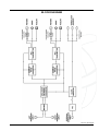
1
DRAWMER
A2D2
DMS-3
AES GRADE 1 DUAL OUTPUT
ANALOGUE TO DIGITAL CONVERTER
CONTENTS
Warranty . . . . . . . . . . . . . . . . . . . . . . . . . . . . . . . . . . . . . . . . . . . . . . . . . . . . . . . . . . . 2
Safety Consideration . . . . . . . . . . . . . . . . . . . . . . . . . . . . . . . . . . . . . . . . . . . . . . . . . 2
Radio Frequencies Statement . . . . . . . . . . . . . . . . . . . . . . . . . . . . . . . . . . . . . . . . . 2
Chapter 1 - Introduction
Introduction . . . . . . . . . . . . . . . . . . . . . . . . . . . . . . . . . . . . . . . . . . . . . . . . . . . . . . . . 3
Installation . . . . . . . . . . . . . . . . . . . . . . . . . . . . . . . . . . . . . . . . . . . . . . . . . . . . . . . . 4
Power Connection . . . . . . . . . . . . . . . . . . . . . . . . . . . . . . . . . . . . . . . . . . . . . . . . . . 4
Audio Connections & Guide . . . . . . . . . . . . . . . . . . . . . . . . . . . . . . . . . . . . . . . . . . 4
Chapter 2 - Control Description
Control Description . . . . . . . . . . . . . . . . . . . . . . . . . . . . . . . . . . . . . . . . . . . . . . . . . 6
Simple Setup Procedure. . . . . . . . . . . . . . . . . . . . . . . . . . . . . . . . . . . . . . . . . . . . . 7
Chapter 3 - General Information
If a fault develops . . . . . . . . . . . . . . . . . . . . . . . . . . . . . . . . . . . . . . . . . . . . . . . . . . 8
Contacting Drawmer . . . . . . . . . . . . . . . . . . . . . . . . . . . . . . . . . . . . . . . . . . . . . . . 8
Specification . . . . . . . . . . . . . . . . . . . . . . . . . . . . . . . . . . . . . . . . . . . . . . . . . . . . . . 8
Block Diagram . . . . . . . . . . . . . . . . . . . . . . . . . . . . . . . . . . . . . . . . . . . . . . . . . . . . . 9
COPYRIGHT
This manual is copyrighted © 2008 by Drawmer Electronics Ltd. With all rights reserved. Under copyright laws, no part of this publication may
be reproduced, transmitted, stored in a retrieval system or translated into any language in any form by any means, mechanical, optical,
electronic, recording, or otherwise, without the written permission of Drawmer Electronics Ltd.
ONE YEAR LIMITED WARRANTY
Drawmer Electronics Ltd., warrants the Drawmer DMS-3 A2D2, AES Grade 1
Dual Output Analogue to Digital Converter to conform substantially to the
specifications of this manual for a period of one year from the original date of
purchase when used in accordance with the specifications detailed in this manual.
In the case of a valid warranty claim, your sole and exclusive remedy and
Drawmer’s entire liability under any theory of liability will be to, at Drawmer’s
discretion, repair or replace the product without charge, or, if not possible, to
refund the purchase price to you. This warranty is not transferable. It applies
only to the original purchaser of the product.
For warranty service please call your local Drawmer dealer. Alternatively call
Drawmer Electronics Ltd. at +44 (0)1709 527574. Then ship the defective product,
with transportation and insurance charges pre-paid, to Drawmer Electronics Ltd.,
Coleman Street, Parkgate, Rotherham, S62 6EL UK. Write the RA number in
large letters in a prominent position on the shipping box. Enclose your name,
address, telephone number, copy of the original sales invoice and a detailed
description of the problem. Drawmer will not accept responsibility for loss or
damage during transit.
This warranty is void if the product has been damaged by misuse, modification
or unauthorised repair.
THIS WARRANTY IS IN LIEU OF ALL WARRANTIES, WHETHER ORAL OR
WRITTEN, EXPRESSED, IMPLIED OR STATUTORY. DRAWMER MAKES NO
OTHER WARRANTY EITHER EXPRESS OR IMPLIED, INCLUDING, WITHOUT
LIMITATION, ANY IMPLIED WARRANTIES OF MERCHANTABILITY, FITNESS
FOR A PARTICULAR PURPOSE, OR NON-INFRINGEMENT. PURCHASER’S
SOLE AND EXCLUSIVE REMEDY UNDER THIS WARRANTY SHALL BE REPAIR
OR REPLACEMENT AS SPECIFIED HEREIN.
IN NO EVENT WILL DRAWMER ELECTRONICS LTD. BE LIABLE FOR ANY
DIRECT, INDIRECT, SPECIAL, INCIDENTAL OR CONSEQUENTIAL DAMAGES
RESULTING FROM ANY DEFECT IN THE PRODUCT, INCLUDING LOST
PROFITS, DAMAGE TO PROPERTY, AND, TO THE EXTENT PERMITTED BY
LAW, DAMAGE FOR PERSONAL INJURY, EVEN IF DRAWMER HAS BEEN
ADVISED OF THE POSSIBILITY OF SUCH DAMAGES.
Some states and specific countries do not allow the exclusion of implied warranties
or limitations on how long an implied warranty may last, so the above limitations
may not apply to you. This warranty gives you specific legal rights. You may
have additional rights that vary from state to state, and country to country.
DRA
WMER
DRAWMER
A2D2
DMS-3
AES GRADE 1 DUAL
OUTPUT ANALOGUE TO
DIGITAL CONVERTER
SAFETY CONSIDERATIONS
CAUTION - MAINS FUSE
TO REDUCE THE RISK OF FIRE
REPLACE THE MAINS FUSE ONLY WITH
A FUSE THAT CONFORMS TO IEC127-2.
250 VOLT WORKING, TIME DELAY TYPE
AND BODY SIZE OF 20mm x 5mm.
THE MAINS INPUT FUSE MUST BE
RATED AT 230V=T80mA and 115V=T160mA.
For the USA
FEDERAL COMMUNICATIONS COMMISSION RADIO
FREQUENCY INTERFERENCE STATEMENT
This equipment has been tested and found to comply with the limits for a Class
B digital device, pursuant to Part 15 of the FCC Rules. These limits are designed
to provide reasonable protection against harmful interference in a residential
installation. This equipment generates, uses and can radiate radio frequency
energy and, if not installed and used in accordance with the instructions, may
cause harmful interference to radio communications. However, there is no
guarantee that interference will not occur in a particular installation. If this
equipment does cause interference to radio or television reception, which can be
determined by turning the equipment off an on, then the user is encouraged to
try to correct the interference by one or more of the following measures:
Re-orient or relocate the receiving antenna.
Increase the separation between the equipment and the receiver.
Connect the equipment into an outlet on a circuit different from
that to which the receiver is connected.
Consult the dealer or an experienced radio/TV
technician for help.
Unauthorised changes or modification to this system can void the users’ authority
to operate this equipment.
This equipment requires shielded interface cables in order to meet FCC class B
limit.
For Canada
CAUTION - MAINS CABLE
DO NOT ATTEMPT TO CHANGE
OR TAMPER WITH THE
SUPPLIED MAINS CABLE.
CAUTION - SERVICING
DO NOT PERFORM ANY SERVICING.
REFER ALL SERVICING TO QUALIFIED
SERVICE PERSONNEL.
WARNING
TO REDUCE THE RISK OF FIRE OR
ELECTRIC SHOCK DO NOT EXPOSE
THIS EQUIPMENT TO RAIN OR MOISTURE.
CLASS B
NOTICE
This digital apparatus does not exceed the Class B limits for radio noise emissions
set out in the Radio Interference Regulations of the Canadian Department of
Communications.
CLASSE B
AVIS
Cet appareil numérique ne dépasse pas les limites de la classe B au niveau des
émissions de bruits radioélectriques fixés dans le Règlement des signaux parasites
par le ministère Canadien des Communications.
In the interests of product development, Drawmer reserve the right to modify or
improve specifications of this product at any time, without prior notice.
2
CHAPTER 1
DRAWMER A2D2
DMS-3: AES GRADE 1 DUAL OUTPUT A/D CONVERTER
INTRODUCTION
Microphones are analogue, speakers are analogue, storage is mostly digital
and signal processing can be either analogue or digital, software or hardware
based. At some point in the signal path, a high quality Analogue-to-Digital
converter is required, which faithfully reproduces analogue signals in the digital
domain. Step up the Drawmer A2D2...
The A2D2 is a stereo A/D converter giving simultaneous dual stereo outputs at
different selectable sample rates from 44.1kHz to 192kHz - so it is possible to
have a main output at, say 192kHz with another at 44.1kHz as a low resolution
copy.
Features:
Dual input configuration allows either a fully variable input level from -2dBu to +28dBu via front
panel rotary controls or 24 turn precision presets for a fully calibrated input.
Accurate 24 segment peak reading LED bar meters show incoming signal levels from -50dBfs to
0dBfs plus separate overload LEDs.
Each digital output has selectable word length of 16 or 24 bits, with automatic dither generation.
The internal low jitter clock generator is Grade 1 AES standard.
External clock input.
3 word clock outputs to allow the A2D2 to act as master clock generator.
Burr Brown analogue input stages.
The A2D2 uses a linear power supply to minimise interference with the internal clocks.
1
2
1 Input Level for 0dBfs:
3
10
6 Analogue Input:
Individual Left/Right Balanced analogue
inputs.
9 Wordclock Input:
The EXT Wordclock input for both
sample rate converters.
5
2 Output Sample Rate:
Two input level modes are available: In
installations with fixed input levels,
Calibrated, recessed left/right, 20 turn
pots give precise input levels where very
little setup is required. In situations where
adjustments have to be made “on the fly”
4
standard Variable left/right controls are
provided.
11
4
9
3 Word Length:
Independantly sets the sample rates for
Output 1 7 and output 2 8 from 44kHz
through to 192kHz, plus EXT clock 9 . A
lock led shows the strength of the incoming
external clock.
On Led:
A LED to show that the unit has power.
8
7
7 Digital Output 1:
One each of S/PDIF, TOSLINK or AES
simultaneous outputs. The sample rate is
selected via 2 .
10 Wordclock Outputs:
Three wordclock outputs provided. The
sample rate is determined by O.S.R.1 2 .
Independantly sets the Word Length of
Output 1 7 and output 2 8 to either
16 bit Dither or 24 Bit.
5 Output Meter:
V.U. output meter with 24 segment LED
per channel plus Overload - ranging from
-50dB to 0 db.
6
8 Digital Output 2:
One each of S/PDIF, TOSLINK or AES
simultaneous outputs. The sample rate is
selected via 2 .
11 IEC and Fuse:
The mains IEC inlet and fuse holder.
3
INSTALLATION
The DMS-3 is designed for standard 19" rack mounting occupying 1U of rack space. Avoid mounting the unit directly above power
supplies or amplifiers that radiate significant amounts of heat. If the unit is to be used in a mobile situation, it is strongly
recommended that the rear of the unit is supported in the carrying rack to avoid bending the front panel rack mounting ‘ears’. Use
fibre or plastic washers to prevent the front panel becoming marked by the mounting bolts.
POWER CONNECTION
The A2D2 will be supplied with a power cable suitable for domestic power outlets in your country. For your own safety, it is
important that you use this cable to connect to the mains supply earth. The cable must not be tampered with or modified.
The power supply socket has an integral fuse drawer containing
the power fuse of the same value, to suit the mains voltage for
which the unit has been supplied. Removal of the drawer is only
possible with the power cord removed. The fuse should never
blow under normal operation. If the fuse is suspected of having
blown, then a fault will have occurred and this fault condition should
be inspected by a qualified service engineer. When replacing the
fuse, always comply with the Safety Instructions.
If the unit is to be used with a mains input operating voltage
different to that for which the unit is supplied, the following procedure must be carried
out by a technically competent person, (see following diagram)
VS SWITCH
FUSE
1: Disconnect the unit from the mains.
2: Using a number 1 size pozidrive screwdriver, remove the nine self -tapping
screws that retain the top cover. Five screws are located on the top cover; and two
screws on either side. Slide off the cover.
3: Inside the unit slide the voltage change-over switch (VS1) until the correct (or
nearest) mains input voltage is visible on the switch actuator.
(see fig.4)
4: Replace the cover and the nine screws.
5: In the fuse draw change the fuse to suit the following values:
For 230 Volt operation alter the fuse to a similar type rated at T80mA.
For 115 Volt operation alter the fuse to a similar type rated at T160mA.
AUDIO CONNECTIONS
Analogue Inputs
The preffered inputs to the A2D2 are electronically balanced
and would normally be connected to your system via a
patchbay. Should unbalanced operation be required, simply
ground pin 3 on the XLR connectors.
If earth loop hum problems are encountered, do not disconnect
the mains earth but instead, try disconnecting one end of the
signal screen on the cables connecting the A2D2 to the
patchbay. If such measures are necessary, balanced operation
is recommended.
AES Input
Via an XLR connector designed to be used with standard
balanced microphone cable (20 metres maximum), wired pin
1 screen, pin 2 and 3 balanced data, and the XLR shell
connected to the chassis. Having many short cables joined
together is not advisable as each connector can cause
undesirable signal reflections.
The output socket fully conforms to the EMC standards; if the
unit is to be used where it may be exposed to high levels of
disturbance, such as found close to a TV or radio transmitter,
it is suggested that the screen of the data cable be connected
to the chassis connection on the XLR type connector rather
than to pin 1.
If ground loop problems are encountered, never disconnect
the mains ground, but instead, try disconnecting the signal
screen on one end of each cable connecting the outputs.
4
S/PDIF Input
Via a high quality RCA type phono jack where the data conforms
to the SonyJ PhillipsJ Digital InterFace format. Because
this connector only provides an unbalanced termination, the
recommended maximum length for this cable is 3 metres,
even with very high quality cable.
TOSLINK (or EIAJ)
The real benefit of TOSlink is that it is not susceptible to
electromagnetic noise, however, it is highly recommended
that a very good quality cable is used as the plastic conductors
used in cheap cables can damage data. Additionally
performance is compromised over long lengths of cable, as
the signal strength weakens due to impurities in the conductive
material, therefore lengths of no longer than five metres are
recommended unless using a signal booster..
Though the connectors are the same TOSLink and ADAT
Optical are not compatible with each other.
Word Clock
Use only good quality digital or video coax (not aerial
downlead) cable for the word-clock signals, terminated with
the correct type of 75Ω BNC connectors - inferior cables will
introduce jitter and will completely undermine the
performance benefits which might be achieved by using a
master clock in the first place!
SIMPLE CONNECTION GUIDE
5
CHAPTER 2
CONTROL DESCRIPTION
The Drawmer DMS-3 A2D2 has been meticulously designed
to faithfully, and transparently recreate your analogue signal
in digital in as simple and intuative method as possible. A
high quality Burr Brown input stage has been incorporated,
coupled with the AES Grade 1 digital converted outputs,
making the A2D2 perfect for recording, mastering and post-
production from all of your analogue to digital devices. The
analogue input is fed simultaneously to two seperately
controlled outputs both in AES/EBU, SPDIF and TOSLINK
formats enabling a backup copy to be made of the signal, as
well as solving any connectivity problems and allowing signal
distribution.
INPUT LEVEL for 0dBfs
MODE
One switch toggles between Variable and Calibrated modes of input level gain.
VARIABLE
In situations where the input levels can vary from place to place, such as in outside broadcasts, or
live venues, a variable input level has been provided, with accurate individual left/right control, to
provide quick setup. This ranges from +28dBU to 0dBU.
CALIBRATED
In the studio, where input and output levels will be calibrated and under better control, a calibrated
input gain option has been provided, in the form of very accurate (24 turn) left/right potentiometers
ranging from +28dBU to 0dBU. These require a small screwdriver to operate and so once set are
less likely to be accidentally adjusted.
Output Sample Rate
The A2D2 has dual independant stereo digital outputs at different selectable sample rates from 44.1kHz to 192kHz - so it is
possible to have a main output at 192kHz with another at 44.1kHz as a low resolution copy.
O/P 1
The outgoing sample rate for O/P1 of the DMS-3 can be set using the two sample rate switches on the top
row - the left moving down rate and the right moving up, with a corresponding LED being lit to show the
current sample rate. The DSM-3 generates six Ultra Low Jitter sample rates - 44.1k, 48k, 88.2k, 96k, 176.4k
and 192k, all stable to <1ppm, and in addition can also operate at the sample rate generated by an external
source. With the Leds set to EXT the sample rate is set by the Wordclock input (as located on the rear panel).
A lock LED is provided on the front and operates when the EXT clock signal is strong.
O/P 1 also sets the sample rate of the three wordclock outputs on the rear panel.
W/Length
The top switch provides either 16 Bit Dither or 24 Bit operation for O/P1.
O/P 2
The outgoing sample rate for O/P2 can be set using the two sample rate switches on the bottom row and
operates in exactly the same way as with O/P1. When on EXT the sample rate is set using the same
Wordclock input as with O/P1.
W/Length
The bottom switch provides either 16 Bit Dither or 24 Bit operation for O/P2.
6
Output Level Metering
An accurate 24 segment peak reading LED bar meter shows the incoming signal level from
-50dBfs to 0dBfs plus separate overload LEDs for each channel.
QUICK SETUP PROCEDURE
. Plug in the left and right channel inputs on the rear of the unit, preferably using balanced wiring.
. On the front panel set the “Input Level for 0dBfs” mode switch to the correct setting - calibrated
if in a studio and the entire system is calibrated, or variable in any other situation.
. Whilst paying close attention to the Output Level Meter, adjust the relevant input gain (The input
controls are analogue and thus measured in dBU whilst the meter displays the digital output of the
unit in dBfs, hence the +28 to 0 dBU controls). The levels should be set so that the meter is as
close to 0dBfs as possible without drifting into overload, to obtain the optimum output levels.
. With your desired digital equipment connected to the any of the O/P 1 digital outputs (they work
simultaneously), and also connected to the wordclock outputs, on the front panel set the top row
(O/P1) of the Output Sample Rate to the desired rate, and set the Bit Depth.
. Where a digital backup of your audio is required, connect the equipment to the O/P 2 digital
outputs on the rear panel, and set the bottom row (O/P2) of the Output Sample Rate to the
desired rate, and set the Bit Depth.
. If you wish to set the wordclock using an external source, plug in the device to the Wordclock
Input on the rear panel and set either or both Output Sample Rates to EXT. If the signal is strong
the Lock led will light, if weak or unstable the Led will flicker or not light at all. In this case the
external device and wiring should be checked.
7
CHAPTER 3
A2D2 DMS-3 GENERAL INFORMATION
SPECIFICATION
IF A FAULT DEVELOPS
For warranty service please call Drawmer Electronics Ltd. or
their nearest authorised service facility, giving full details of
the difficulty.
Analogue Inputs
Left/Right balanced XLR
(Pin 2 Hot)
Frequency Response
20Hz-20kHz +/- 0.1dB
A list of all main dealers can be found on the Drawmer
webpages.
Input Level Range for 0dBFs
-2.0dBU to +28dBU
Crosstalk
-103dBFs @ 1kHz
-84dBFs @ 10kHz
Factory Calibration of Presets
+18dBU = 0dBFs
THD+Noise
0dBFs >101 dBFs
-1dBFs >103dBFs
-3dBFs >105dBFs
-6dBFs >107dBFs
-12dBFs >110dBFs
On receipt of this information, service or shipping instructions
will be forwarded to you.
No equipment should be returned under the warranty without
prior consent from Drawmer or their authorised representative.
For service claims under the warranty agreement a service
Returns Authorisation (RA) number will be issued.
Write this RA number in large letters in a prominent position
on the shipping box. Enclose your name, address, telephone
number, copy of the original sales invoice and a detailed
description of the problem.
A/D Converter
2 x Temperature Compensated Xtal Oscillators (TCXOs)
AES GRADE 1 Stability,
Tolerance
Authorised returns should be prepaid and must be insured.
All Drawmer products are packaged in specially designed
containers for protection. If the unit is to be returned, the original
container must be used. If this container is not available, then
the equipment should be packaged in substantial shock-proof
material, capable of withstanding the handling for the transit.
CONTACTING DRAWMER
Drawmer Electronics Ltd., will be pleased to answer all
application questions to enhance your usage of this
equipment. Please address correspondence to:
Drawmer (Technical Help line)
Coleman Street
Parkgate
Rotherham
S62 6EL
UK
Alternatively contact us by E-mail on :
2 x Stereo Sample
Rate Converters:
http://www.drawmer.com
8
full up/down conversion
44.1, 48, 88.2, 96, 176.4,
and 192kHz
2 x AES/EBU Neutrik XLR
Neutrik XLR
2 x S/PDIF Outputs
Coaxial, RCA Type
2 x TOSLink
JIS F05
Bit Depth
24Bit and 16Bit Dither
Word Clock Outputs
Output impedance
22.5 ohms giving 4v
pk-pk into 75 ohms
General
Power Supply:
230Volt or 115V at
50-60hZ, 16VA
Fuse Rating
80mA for 230Volt,
160mA for 115Volt.
CONFORMING TO:
IEC127-2
Fuse Type
20mm x 5mm, Class 3
Slow - Blow
250Volt working
Dimensions:
1u, 19" Rack Mount,
482mm(W) x 44mm(H) x
145mm(D)
Weight
2.213 kg
[email protected]
Further information on all Drawmer dealers, Authorised service
departments and other contact information can be obtained
from our web pages on:
+/-1ppm (0-60 Celcius),
<<+/-1ppm (15-30
Celcius)
BLOCK DIAGRAM
Ref:1v01 B 09-09-08
9
10