1
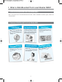
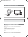
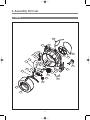
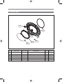
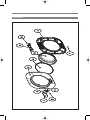
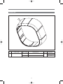
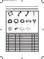
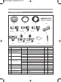
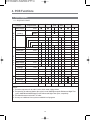
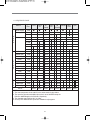
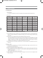
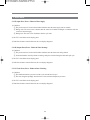
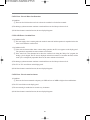
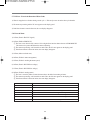
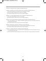
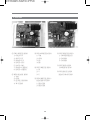
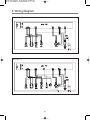
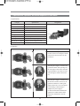
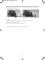
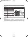
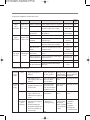
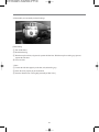
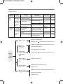
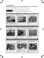
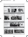
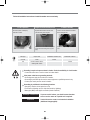
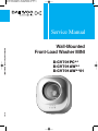
Service Manual Wall-Mounted Front-Load Washer MINI Wall-Mounted Front-Load Washer MINI D-CV701PC** D-CV701AW** D-CV701AW**01 2012.09 c 1. What is Wall-Mounted Front-Load Washer MINI? ............................................2 2. Specifications ......................................................................................................4 3. Assembly Part List ..............................................................................................5 4. PCB Functions ..................................................................................................14 5. Wiring Diagram .................................................................................................29 6. Part List and Major Specifications ....................................................................30 7. Installation .........................................................................................................47 1. What is Wall-Mounted Front Load Washer MINI? 1. What is the Wall-Mounted Front-Load Washer MINI? Mini is the world's first ever wall-mounted front-load washer, which is installable in bathroom, pantry, kitchen and various locations. 2. Features of Wall-Mounted Front-Load Washer MINI Low Noise low-noise motor Mini's customized ring wash, and reduces noise du stp ro of pa d du ed er th e 4- lay ensure silent to s prevents vibration . washing Spoon-Shaped Detergent Container Containers for detergent and softener are discretely designed to prevent mixture. The spoon-shaped design enables you to apply the proper amount of detergent conveniently. Transparent Door Child Protection Tran spar ent door allow s you to view the cont ents and chec k laundry process. 'But ton Lock ' and 'Doo r Lock ' functions apply to prevent kids from touching buttons and opening doors during wash. 2 Star Drum Star-shaped concave-convex drum prevents damage to fabric to keep clothes fresh. ograms Cleaning Pr r various es fo ram featur Mini's prog fabrics. an rposes d cleaning pu 3. Power Train of Wall-Mounted Front-Load Washer MINI Tub Load Drum Natural drainage Inverter Motor Natural drainage system • Inverter Motor: Transforms electric energy into mechanical energy • Highly powerful and functional inverter motor rotates the system. 4. Major Features of Wall-Mounted Front-Load Washer MINI 1. Powerful Daily Cleaning Mini enables daily washes of towels, shirts, underwear and socks for cleaner home environment. 2. 29-Minute Wash As the Normal cycle takes only 29 minutes, it speeds up the laundry process and reduces water and power consumption by 64% compared to regular front-load washers. 3. Baby Clothes Cleaning (D-CV701PC**, D-CV701AW**) Mini's 'Baby Care' cycle enables a complete steam wash and rinse function to protect sensitive baby skin from irritation. 4. Delicate Cleaning for High-Quality Clothes Mini enables daily washes of towels, shirts, underwear and socks for cleaner home environment. 3 2. Specifications 1. Parts and Components 1 2 3 4 5 NO Parts 1 TUB REAR 2 BODY 3 DOOR PROTECTOR 4 DOOR HANDLE 5 DOOR FRAME *O 6 BODY COVER 6 Category Specifications Dimension 550mmX600mmX292mm(WXHXD) Weight 16.5KG Standard Volume 28L Power 220V, 50/60Hz Notes Power Wash 100W D-CV701PC**/701AW**/701AW**01 Consumption Steam 1500W D-CV701PC**/AW** Standard Wash 3KG Load Spin 3KG Washer Type Front Load Installation Mounted on Wall Water Pressure 98.1KPA~784KPA (1KGf/cm2~8KGf/CM2) 4 3. Assembly Part List 1. TUB AS A26 A25 A24 A23 A22 A29 A21 A27 A28 A13 A12 A11 A14 A15 A10 A30 A04 A16 A09 A20 A05 A03 A19 A18 A17 A06 A08 A07 A02 A01 5 A32 A31 No. PART NAME PART CODE A01 A02 A03 A04 A26 A27 A28 A29 A30 DRUM SUB AS LIFTER WASH SPIDER AS SPECIAL BOLT DRAIN MOTOR AS DRAIN MOTOR DRAIN HOUSING CAP FILTER DRAIN PACKING CAP FILTER DRAIN HOSE AIR TRAP CLAMP HOSE AIR TRAP HOSE AIR SENSOR PRESSURE EMI FILTER FIXTURE HEATER HEATER WASH INVERTER MOTOR SPECIAL BOLT SPECIAL SCREW BRACKET EARTH VALVE CHECK AS(1/4") Y DIVIDER HOSE INLET VALVE INLET TUB REAR SUB AS BEARING INNER WATER SEAL DRAIN HOUSING BOND HOSE VENT AS PULLEY SPECIAL BOLT AS BELT V HARNESS AS A31 MAIN PCB AS A32 REACTOR 3617030010 361A401900 361A301610 3616063000 3919601110 3919601100 36196TC010 36196TC050 36196TC060 3613276800 3611204700 361A500300 3613276900 3614825320 3611913000 3612007310 3612804000 36189L8000 3616067000 7S422X4081 3610603500 3615418450 3612512900 3613270980 3615401000 3618831620 3616305900 361A600900 36196TC000 2224050106 3613217940 3618434300 3616063110 3616591600 361279C000 361279C010 361279C020 361279C030 361NPCB942 361NPCB943 361NPCB946 361NPCB947 3615800500 A05 A06 A07 A08 A09 A10 A11 A12 A13 A14 A15 A16 A17 A18 A19 A20 A21 A22 A23 A24 A25 DESCRIPTION Q’TY D-M300 1 D-M300, PP 3 D-M300 1 STS430 M6*21 SI-LOCK 3 SAMCO, NEW 220~240V 50/60HZ 5/6RPM PV ASM 1 SAMCO, 220V 5/6RPM,SSM-16HR 1 D-M300, FRPP, FILTER TYPE 1 D-M300, FRPP, FILTER TYPE 1 D-M300, NBR 40 1 D-M300, EPDM 1 ID27 2 D-M300, PP 1 D-M300, EPDM ID=4 OD=8, L=455 1 DL-DW12-H AIR INLET 270 HOOK TYPE 1 DFC-2712D ,250V 12A, 1 SUS 304 0.7T 440X45 1 1 220V.140MM.1400W.TERMINAL 1R8A721.IRCA FUSE 2EA 1 DWD200BL, DC 310 V, 125 W, CLASS F 1 TRS S/W P/W HEX:5*16 SUS304 4 TT3 TRS 4X8 SE MFZN 2 SBHG1 T1.2 1 D-M300,1/4",POM 1 D-M300, ATWD0404 1/4' DMT 1 DFE04 LLDPE ID=4,OD=6 0.575 AC 220V/60HZ, SV-11CWB-01,1WAY 2 D-M300. TUB REAR+BEARING HOUSING 1 D-M300,6203ZZ,ID=17,OD=40 1 D-M300,NBR ID=25,OD=50 1 FRPP 1 218W 0.005 D-M300 HOSE VENT AS 1 D-M300, ALDC 1 M8X27 S/W P/W SI-LOCK HEX:13 1 D-M300, 4PJ-1020 1 D-M301 ,MINI WASH,FULL OPTION 1 D-M300 ,MINI WASH,NON HEATER 1 D-M301 ,MINI WASH,FULL OPTION,NON EMI 1 D-M300, MINI WASH,NON HEATER,NON EMI 1 MINI,V.E,220,J,COLD+HEATER-O,NO-EMI(PERU,ARAB) 1 MINI,V.E,220,J,COLD+HEATER-O,EMI(RUSSIA) 1 MINI,V.E,220,J,COLD+HEATER-X,NO-EMI(PERU,ARAB) 1 MINI,V.E,220,J,COLD+HEATER-O,EMI(CHINA) 1 RT-028 L=3.6MH(0A),L=5.2MH(1A) 1 6 REMARK DRAIN MOTOR ASSMBLY TUB REAR ASSMBLY OPTION 2. COVER TUB AS B03 B06 B04 B02 B05 B01 No. B01 B02 B03 B04 B05 B06 PART NAME PART CODE DESCRIPTION CLAMP GASKET AS 3611204540 D-M300, D1.4 GASKET DOOR 3612328000 D-M300,EPDM PACKING DETERGENT PRPKCA3R80 D-M300, NBR COVER TUB 3618831700 D-M300, FRPP SCREW TAPPING 7122502508 T2S TRS 5*25 SUS GASKET TUB 3612326100 D-M300, PI=4.5,EPDML=1385 7 Q’TY 1 1 2 1 15 1 REMARK 3. COVER BODY AS C01 C02 C03 C07 C04 C08 C06 C05 No. PART NAME PART CODE DESCRIPTION Q’TY C01 C02 C03 C04 C05 C06 C07 C08 COVER BODY CASE DETERGENT HANDLE DETERGENT CAP SCREW DECORATOR FILM PCB AS SWITCH DOOR LOCK CASE PCB F 361081WG01 36111T3J00 3612613121 3610917731 36116DWQ01 PRPSSWD100 3619047230 36111T3L00 D-M300,ABS,SPRAY D-M300, PP D-M300, ABS, SPRAY D-M300, ABS, SPRAY D-M301, PET D-M301 FRONT PCB AS, H/T DL-S2,DM. 250V16A.BITRON.VE-TYPE,CONCORE D-M300,HIPS 1 2 2 6 1 1 1 1 8 REMARK 4. DOOR AS 9 No. PART NAME PART CODE DESCRIPTION D01 HANDLE DOOR 3612614801 D-M301, ABS, CR-GILDING 3612614800 D-M300, ABS Q’TY 1 D-CV701PC** D-CV701AW**** D02 PIN HANDLE 3618200200 SUS304, D3, L48 1 D03 HOOK SPRING 3615119400 SUS D1.6 L40 1 D04 HOOK DOOR 3613102000 D-M300, ZNDC 1 D05 FRAME DOO*O 36117AE101 D-M301, ABS, CR-GRLDING 36117AE100 D-M300, ABS 1 D-CV701PC** D-CV701AW**** D06 PROTECTOR GLASS 3618304900 D-M300, TR ABS 1 D07 DOOR *I 361A114500 D-M300, TR-PETG 1 D08 HINGE DOOR 3612904800 D-M300, ALDC 1 D09 CAP HINGE DOOR 3610916500 POM 2 D10 FRAME DOOR *I 36117AE200 D-M300, PP 1 D11 SCREW TAPPING 7115401629 T1 FLT 4X16 SUS 11 10 REMARK 5. BODY AS E01 No. E01 PART NAME BODY AS PART CODE DESCRIPTION 361081WF11 D-M301 361081WF10 D-M300, ABS 11 Q’TY 1 REMARK D-CV701PC** D-CV701AW**** 6. PACKING AS F01 F05 F02 F03 F06 F07 er Us F10 F11 F04 F08 l nua Ma F12 e uid ll G ta Ins F09 F13 No. PART NAME PART CODE DESCRIPTION F01 CUSHION BOTTOM 3611580000 D-M300,EPS 1 F02 CUSHION *L 3611578000 D-M300,EPS 1 F03 CUSHION *R 3611579000 D-M300,EPS 1 F04 ANCHOR BOLT AS 3616067100 3/8"(M10),SUS,L=6"/BASIC, P/W 2T 30MM,LOCK NUT 4 F05 HOSE DRAIN OUTER AS 3613275800 D-M300. PVC, L=3M, CLAMP, ID=10,OD:14 1 F06 HOSE INLET 3613270980 DFE04 LLDPE ID=4,OD=6 1 F07 CORD POWER AS 3611308100 3M, MINI DRUM 1 F08 ELBOW UNION 3612512800 D-M300, AEU0404W 1/4' DMT 3 F09 CONNECTOR VALVE INLET 3619513100 D-M300, SMALL ID=19 OD=20.6 / BASIC 1 F10 CUSHION PAD 3611535360 D-M300, EPDM 3T ID=10, OD=70 4 F11 SCREW TAPPING 7115401629 T1 FLT 4X16 SUS 4 F12 MANUAL OWNERS 3613926450 D-M300 1 F13 INSTALL GUIDE 3612513000 D-M300 1 12 ARD LL C TA INS Q’TY REMARK 7. Further parts for install G01 G02 <MIDDLE> <LARGE> G03 G04 <ROYAL> G05 G06 all t Ins <HOOK TYPE> G07 No. PART NAME <SCREW TYPE> G08 PART CODE ide Gu G09 DESCRIPTION G10 Q’TY REMARK 300M/1Roll G01 HOSE INLET 3613270980 DFE04 LLDPE ID=4,OD=6 1 G02 HOSE DRAIN *O 3613275839 SVC,D-M300. PE-LD, ID=14,OD=18,L=1M 1 G03 POWER CORD AS 3611308100 3M, MINI DRUM 1 3611308200 5M, MINI DRUM 1 3610088170 PVC 1M MH-3 MID #4 DUCKSUNG ACRYLIC FOAM,NEW WHITE 1 3610088180 PVC 1M MH-3 MID #2 DUCKSUNG ACRYLIC FOAM,NEW WHITE 1 CONNECTOR 3619513200 D-M300, MIDDLE ID=23 OD=24.8 / OPTION 1 VALVE INLET 3619513300 D-M300, LARGE ID=24.4 OD=26.3 / OPTION 1 3619513400 D-M300, ROYAL ID=26.6 OD=27.8 / OPTION 1 G04 G05 MOLDING AS G06 Union Connector 3612512810 AUC0404W 1/4' DMT 1 G07 TEE UNION 3612512820 D-M300, ATU0404W 1/4' DMT 1 G08 ADAPTER INLET 3613278000 D-M300, HOOK TYPE 1 VALVE AS 3613279000 D-M300, SCREW TYPE 1 G09 INSTALL GUIDE 3612513000 D-M300 1 G10 ANCHOR BOLT AS 3616067200 3/8"(M10),SUS,L=8"/OPTION, P/W 2T 30MM,LOCK NUT 4 13 4. PCB Functions 1. Cycle Programs 1.1.1 SEQUENCE CHART Category W a s h Progress Time Water Supply 2 min Wash 1 33 min (Heating) 10 min Wash 2 27 min Normal Delicate ᵉ ᵉ 29 min 32 min Baby Care Night Time Spin Tub clean ᵉ ᵉ ᵉ 40 min 5 min 31 min 11 min 10 min 8 min 4 min R i n s e S p i n Drain 1 min Middle Spin 2 min Water Supply 2 min Rinse 1 2 min Drain 1 min Middle Spin 2 min Water Supply 2 min Rinse 2 2 min Drainage 1 min Middle Spin 2 min Water Supply 2 min Rinse 3 2 min Drain 1 min Main Spin 3 min Unlocking 1 min TOTAL 65 min NOTE 1. The water temperature is set at 80°C for the steam wash of baby clothes. 2. The speed for the main and interim spin cycles is set at 700RPM except the Delicate and Night Time cycles. 400RPM and 500RPM apply to the Delicate and Night Time cycles, respectively. 3. The drainable water must be 50°C or colder. 4. As many as 5 additional rinse cycles are available for all programs. 14 1.1.2 SEQUENCE CHART Division W A S H Progress Time Cotton Cotton Cotton 40 Delicate 60 60 (IEC60456) (IEC60456) Cold Cotton 40 ᵉ ᵉ ᵉ ᵉ ᵉ 35min Water Supply 2min Heating Wash 33min 15min 30min 20min 10min ᵉ ᵉ ᵉ 98min 18min Main Wash 138min 27min Baby Care Spin 65min 5min ᵉ 13min 11min 10min 8min 4min R I N S E S P I N Drain 1min Middle Spin 2min Water Supply 2min Rinse 1 2min Drain 1min Middle Spin 2min Water Supply 2min Rinse 2 2min Drain 1min Middle Spin 2min Water Supply 2min Rinse 3 2min Drain 1min Main Spin 3min Unlocking 1min TOTAL 29min 49min 3min 3min 5min 5min 3min 3min 5min 5min 3min 3min 5min 5min 20min 20min 185min 59min 220min NOTE 1. The water temperature is set at 80°C for the steam wash of baby clothes. 2. The speed for the main and middle spin cycles is set at 700RPM except the Delicate. 400RPM apply to the Delicate, respectively. 3. The drainable water must be 50°C or colder. 4. As many as 5 additional rinse cycles are available for all programs. 15 32min 1.1.3 SEQUENCE CHART Division W A S H Progress Normal Delicate Time ᵉ Baby Care ᵉ Night Time Spin ᵉ Intensive COLD 40 60 (IEC60456) ᵉ ᵉ ᵉ 35min Water Supply 2min Heating Wash 33min 30min 10min ᵉ Main Wash 118min 27min 12min 11min 10min 8min 4min R I N S E S P I N Drain 1min Middle Spin 2min Water Supply 2min Rinse 1 2min Drain 1min Middle Spin 2min Water Supply 2min Rinse 2 2min Drain 1min Middle Spin 2min Water Supply 2min Rinse 3 2min Drain 1min Main Spin 3min Unlocking 1min TOTAL 29min 32min 65min 40min 5min 3min 3min 3min 5min 5min 5min 3min 3min 3min 5min 5min 5min 3min 3min 3min 5min 5min 5min 50min 80min 210min NOTE 1. The water temperature is set at 80°C for the steam wash of baby clothes. 2. The speed for the main and middle spin cycles is set at 700RPM except the Delicate and Night Time cycles. 400RPM and 500RPM apply to the Delicate and Night Time cycles, respectively. 3. The drainable water must be 50°C or colder. 4. As many as 5 additional rinse cycles are available for all programs except the Intensive. 16 1.2. Button Functions No. Buttons 1 Power 2 Program Functional Description When the power button is turned off, the power relay is cut offto sever the common line for electric supply and, accordingly,ensure electrical safety. Premium: Normal->Delicate->Baby Care->Night Time ->Spin->Tub clean Regular: Normal->Delicate->Night Time->Spin->Tub clean Premium: Cold -> Cotton40 -> Cotton 60 -> Delicate -> Baby Care -> Spin Premium: Normal->Delicate->Baby Care->Night Time ->Spin -> Intensive -> Intensive 40 -> Intensive 60 Regular: Normal->Delicate->Night Time->Spin-> Intensive 3 Add Rinse Up to 5 cycles are addable for all programs. Up to 8 additionalcycles are available for 'Baby Care', 'Intensive', 'Intensive40', 'Intensive60' and 'Night Time' while 7 additional cycles are available for 'Normal', 'Delicate', 'Cotton 40', 'Cotton60' and 'Tub clean'. Up to 5 additional cycles are available for 'Spin'. 4 Start/Pause The LED lamp for 'Program' button flickers duringand remains on when the washer stops the cycle. 17 Note 2. Program Functions 2-1. Wash Program 1) Wash Programs 1 The default washing times and water levels apply for all the programs without sensing the load. 2) Wash Times c p w @ t @@ h @ n@O@c d R@ M X@ QP@ d d R@ M QQ@ QS@ b@c d R@ SS@ T@ SY@ n@t d R@ M QR@ QT@ t@ d R@ M QP@ QR@ i d R@ M QP@ QR@ i TP d R@ QU@ RU@ TR@ i VP d R@ RP@ QSU@ QUW@ c@TP d S@ M QS@ QU@ c@VP d T@ M QX@ RP@ w@ t@ * Washing time after the water temperature reaches the target level. 1 The washing time consists of heating cycle and post-heating main wash cycle. The time displayed for heating cycle elapses immediately on completion of heating cycle or remains unchanged until the heating cycle is over. 2 The heating cycle is complete when the water temperature reaches the target level. - If the water temperature doesn't reach the target level after the heating cycle under the Baby Care, Cotton 40, Cotton 60, Intensive 40, Intensive 60, program, the time on display stops declining and an additional heating cycle applies for 10 minutes. If the water temperature doesn't reach the target level after the additional cycle, the heating cycle is suspended and the main wash cycle starts. 3 The water heater does not resume its operation after it is turned off when the water temperature reaches the target level. 3) Resupply of Water 1 The water level is measured every two minutes after the initial water supply to add water if the level is lower than the pre-determined level. 2 The motor stops running during the resupply of water. 3 Water is resuppliable up to 20 times during wash. On the occurrence of the 21st water supply, the "E4" error is displayed and the wash cycle is suspended. -> This error doesn't usually take place because of the short duration of wash program. - Start the pump on the occurrence of the "E4" error. 4 If the water level is below the reset level during the resupply of water, the 'IE' error is displayed and the heater is turned off. 18 4) Detection of Overflow 1 The water level is measured every two minutes after the initial water supply to drain water if the level is above the overflow level. 2 If the water level is measured above the overflow level three times, the 'E3' error is displayed and the wash cycle is suspended. However, the water continues to be drained. 3 If the water level is first measured to be above the overflow level during the "Baby Care" program, the heating cycle is skipped. The 'E3' error is displayed on the third occurrence of overflow detection, and the wash cycle is suspended. However, the water continues to be drained. 4 If the water level is measured to be above the overflow level when the wash cycle is suspended, the 'E2' error takes place but the water continues to be drained. 5) Water Level for Heating Cycle 1 If the water level is measured below the preset level, the heater is turned off to prevent overheating or short circuit during the heating cycle. 19 2-2. Rinse Cycle 1) Drainage 1 If the water is 55°C or hotter, cold water is added to lower the water temperature. When the water temperature decreases to 50°C or lower, water drainage resumes. 2 After the water drainage starts, the drain pump continues to work. 3 If the water level lowers to the reset level within 60 seconds, the waiting time of 20 seconds applies. Otherwise, the waiting time of 40 seconds applies. 2) Intermediate Spin 1 Intermediate spin is run at the pre-determined speed for each program. c p RPM c p RPM c p RPM n WPP c WPP n@ WPP d TPP c@TP WPP d TPP b@c WPP c@VP WPP b@c WPP n@t UPP b@c UPP n@t UPP s M d TPP s M t@ WPP s M i HcLTPLVPI WPP 3) Water Supply 1 Only cold water is supplied to the rinse cycle. 2 Fabric softener is added to the final rinse cycle. 4) Resupply of Water 1 The water level is measured a minute after the rinse cycle starts to determine whether water needs to be added to raise the water level to the preset level. 2-3.Spin Cycle 1) Drainage 1 It is equivalent to the drainage cycle for rinsing. 2-3.Spin Cycle 1) Termination of Door Lock 1 After the electric signal to door lock is cut off, the door is shaken horizontally until it becomes mechanically openable. 20 3. Functional Structure 3-1. Water Supply Level 1) Water Supply Level 1 RESET : It is the water level to start drainage. The spin cycle starts 30 seconds after the reset level is reached. It is the minimum water level to start operating the heater. 2 HEATER OFF : . It is the minimum water level to start operating the heater. The heater starts running only when the water level is above this measure. 3 WASH 1 : Water level for Baby Care program 4 WASH 2 : Water level for Normal, Delicate, Cold, Cotton 40, Cotton 60 or Night time program 5 WASH 3 : Water level for Normal, Delicate, Cotton 40, Cotton 60, Intensive, Intensive 40, Intensive 60 or Night time program 6 LOCK OFF (Water level to unlock door) : Water level to enable to open the door 7 LOCK ON (Water level to lock door) : Water level to lock the door automatically due to the water in the tub. 8 Overflow Level : Water level to start draining water due to overflow risk. The water supply is suspended and the water is drained to lower the level to the reset level if the overflow level is reached. 21 3-2. DOOR S/W 1) DOOR S/W 1 Locking of Door A pulse of 20m sec duty is transmitted twice to the solenoid 3 seconds after the bimetal door switch starts running until the door is locked. The bimetal starts running as soon as the power button is pressed. 2 Unlocking of Door A pulse of 20m sec duty is transmitted to the solenoid after the bimetal door switch is turned off until the door is unlocked 3 The wash cycle is startable as the motor and other parts become available for operation when the door is locked. 4 The door is locked when the water is measured at 61°C or hotter or the water level is above the safety level after the Power button is turned on. 5 The door is unlocked promptly after the cycle is complete. 6 The door is unlocked if it is openable when the cycle is suspended. 3-3. Child Lock 1) Mechanism 1 If the 'Program' and 'Add Rinse' buttons are pressed simultaneously, the Child Lock mode starts running. 2 In the Child Lock mode, all buttons except the Power button (press it for over 1.5 seconds) are unavailable for use. 3 The Child Lock mode is terminated if the 'Program' and 'Add Rinse' buttons are pressed simultaneously. 4 If the Power button is pressed for over 1.5 seconds, the Child Lock mode is terminated. 22 4. TEST MODE 4-1. Part Test Mode 1) Test Start 1 Press the 'Program' button and then select 'Delicate' program. With the 'Program' button pressed, press the 'Add Rinse' button three times to start a test. 2 The product version is displayed after starting a test. 3 Press the 'Program' button to run the washer in the following sequence. Sequence Description Display 1 2 3 4 5 6 7 8 9 10 11 12 13 14 Lock the door Display the durability number Number of hall sensor errors Number of IPM fault errors Number of motor overload errors Number of errors in motor arrangement Number of failures in tracking the motor speed Number of errors in DC LINK overvoltage Number of errors in DC LINK low voltage Number of failures in starting motor Operate the cold water valve Operate the softener valve Operate the drainage valve Unlock the door 'LC' or 'LO' 'rn', 'number' 'b1', 'number' 'b2', 'number' 'b3', 'number' 'b4', 'number' 'b5', 'number' 'b6', 'number' 'b7', 'number' 'b8', 'number' 'C' 'r' 'dr' 'LC', 'LO' 23 5. Error Alerts 5-1. IE (Input Error) Error - Failure in Water Supply 1) Conditions 1 The preset water level is not reached within 20 minutes after the water supply starts or resumes. 2 During wash: The error occurs 4 minutes after the water level remains unchanged or 20 minutes after the water level starts changing. 3 During rinse: The error occurs 20 minutes after the cycle starts. 2) The "LE" error flickers on the display panel. 3) If the Power button is turned off and on, the error display disappears. 5-2.OE (Output Error) Error - Failure in Water Drainage 1) Conditions 1 The preset water level is not reached within 10 minutes after the water starts being drained. 2 Overload situations caused by failures in drainage take place 18 times during the final main spin cycle. 2) The "LE" error flickers on the display panel. 3) If the Power button is turned off and on, the error display disappears. 5-3. LE (Lock Error) Error - Failure in Door Unlocking 1) Conditions 1 The Start/Pause button is pressed to run the cycle when the door is open. 2 The error disappears promptly when the door is closed and the subsequent cycle starts. 2) The "LE" error flickers on the display panel. 3) If the Power button is turned off and on, the error display disappears. 24 5-4. E1 Error - Error in Water Level Detection 1) Conditions 1 The water level is below the reset level or above the overflow level in the line test mode. 2) The drainage synchronous motor continues to work until the water level drops to the reset level. 3) If the Power button is turned off and on, the error display disappears. 5-5. E2 & E3 Errors - Overflow Error 1-1) Conditions for E2 1 The water supply valve is running when the washer is turned off and the operation is suspended so that the water level reaches the overflow level. 1-2) Conditions for E3 1 If the errors are detected three times or more during operation, the 'E3' error appears on the display panel. The operation is suspended, but water continues to be drained. 2 If the water level is first measured to be above the overflow level during the "Baby Care" program, the heating cycle is skipped. The 'E3' error is displayed on the third occurrence of overflow detection, and the wash cycle is subsequently suspended. However, the water continues to be drained. 2) The drainage synchronous motor continues to work until the water level drops to the reset level. 3) The "E2" or "E3" error flickers on the display panel. 4) If the Power button is turned off and on, the error display disappears. 5-6. E9 Error - Error in water level sensor 1) Conditions 1 The water level sensor transmits a frequency of 15KHz or lower or 30KHz or higher due to malfunctions. 2) The "E9" error flickers on the display panel. 3) The error warning is sounded for 10 seconds every 10 minutes. 4) If the Power button is turned off and on, the error display disappears. 25 5-7. E4 Error - Error in the Detection of Water Leaks 1) Water is resupplied over 20 times during a wash cycle. -> This rarely occurs due to the short cycle duration. 2) The motor stops running and the 'E4' error appears on the display panel. 3) If the Power button is turned off and on, the error display disappears. 5-8. Errors in Motor 1) b1 Error (Error in HALL IC signals) 2) b2 Error (EMG or IPMFAULT) 1 The error occurs when electric current of 15A or higher flows into the shunt resistance of IPM-MODULE. The function is to protect PCB from the motor overheating. 2 The motor stops running, and 30 retrials are made. Then, the 'b2' error appears on the display panel. 3 If the Power button is turned off and on, the error display disappears. 3) b3 Error (Motor overload error) 4) b4 Error (Failure in motor arrangement) 5) b5 Error (Failure in tracking the motor speed) 6) b6 Error (Error in DC LINK overvoltage) 7) b7 Error (Error in DC LINK low voltage) 8) b8 Error (Failure in starting motor) 1 The error is caused by failure to rotate the motor due to the initial overrunning of motor. 2 The motor stops running, and 30 retrials are made. Then, the 'b8' error appears on the display panel. 3 If the Power button is turned off and on, the error display disappears. 'b1', 'number' 'b2', 'number' 'b3', 'number' 'b4', 'number' 'b5', 'number' 'b6', 'number' 'b7', 'number' 'b8', 'number' Number of hall sensor errors Number of IPM fault errors Number of motor overload errors Number of errors in motor arrangement Number of failures in tracking the motor speed Number of errors in DC LINK overvoltage Number of errors in DC LINK low voltage Number of failures in starting motor 26 5-10. Errors in Temperature Sensor (Available for premium model only) 1) H2 Error - Open/Short error in washer temperature sensor (Available for premium model only) 1 The washer temperature sensor fails to work or is not properly connected. 2 The error warning is sounded for 10 seconds every 10 minutes. 3 If the Power button is turned off and on, the error display disappears. 2) H4 Error - Overheated washer temperature sensor (Available for premium model only) 1 The sensor temperature turns out to be 125°C or higher. 2 If the Power button is turned off and on, the error display disappears. 3) H5 Error - Error in water temperature for Delicate program (Available for premium model only) 1 The water temperature is 45°C or higher in the Delicate program. (The error occurs during operation only when the tub contains water) 2 If the Power button is turned off and on, the error display disappears. 4) H6 Error - Malfunction of water heater (Available for premium model only) 1 The water temperature fails to rise by 2°C within 30 minutes after the heater starts running. 2 If the Power button is turned off and on, the error display disappears. 5) H8 Error - Overheated water heater (Available for premium model only) 1 The water temperature rises by 6°C or more within 30 seconds after the heater starts running due to the lack of water in tub or other reasons. 2 The water heater doesn't operate although it is functional. The washer is running with the heater turned off. 27 6. PCB PIN 2 3 2 3 4 4 5 5 1 6 8 6 1 7 ῡ fwQHwhite@XpinI QZ@cold@vOv RZ@soft@vOv SZ@drain@vOv TZ@lockMptc UZ@lockMsol WZ@drainMcheck XZ@lockMcheck ῢ wfYHblack@TpinI QZ@v RZ@gnd SZ@level@sensor TZ@wMtemp 7 ΰ wfQPHwhite@TpinI QZ@v RZ@gnd SZ@h TZ@h ῤ wfWHwhite@SpinI QZ@w RZ@v SZ@u ῥ wfVHwhite@RpinI@Z heater@option QZ@heater@ RZ@heater 28 ῦ wfUHwhite@SpinI QZ@power@relay RZ@pOcord SZ@pOcord ῧ wfUHred@SpinI power@option Ῠ wfRHblue@RpinI reactor@option 5. Wiring Diagram D-CV701****01 D-CV701**** 29 6. Part List and Major Specifications NO PART NAME Rating PART CODE BOM DESCRIPTION 1 WASH MOTOR d.c. 310 V, 125 W 36189L8000 DWD200BL, Class F 2 DRAIN MOTOR 220 V, 3 W 3919601000 SDPV-1, Class E 3 VALVE INLET 220 V, 5.5 W 3615401000 SV-11CWB, Class E 4 WASH HEATER 220 V, 1400 W 3612804000 1R8A721 5 FUSE 220 V, 1400 W 1R0X350 250 V, 15 A MAIN FUSE, 326 250 V, 15 A M-PCB, 66TL WASH HEATER entrails (2EA) 6 THERMAL FUSE 220 V, 16 A 7 POWER CORD Assy Korea 3611308101 H05VV-F, 3G, 1.5mm2, 3 M 3611308202 H05VV-F, 3G, 1.5mm2, 5 M 8 POWER PLUG 250 V, 16 A 9 EMI FILTER 250 V, 12 A 10 MICRO SWITCH 11 X-CAPACITOR 275 V M-PCB, CMI, CM15, PCX2 335M, 0.1 ὺ 12 VARISTOR 560 V SVC561-14 13 RELAY 250V, 10 A RY8, GA-1A-12L 250V, 10 A RY5, GI-1A-12DH 250V, 10 A RY8, OMI-SH-112LM 250V, 10 A RY8, SMI-S-112LM 250V, 10 A RY5, SJ-S-112DM 250V, 10 A RY1~4, RY6, Y5-1A-12L 250V, 10 A RY1~4, RY6, PCJ-112D3MH 250V, 10 A RY1~4, RY6, SRB-S-112DM 5KV PC-17K1 14 PHOTO COUPLER 15 TRANSFORMER Maker/ P N Shi LIT SEE-72GE 3611913000 DFC-2712D MS-11D Sam K M-PCB, TS14-14 Nam M-PCB, TS14-14 Wo 16 SENSOR PRESSURE 3614825320 17 THERMISTOR WASH 361AAAAB10 R25=1.704ὶ R80=11.981ὶ 18 HARNESS EARTH 3612794420 19 HARNESS AS 361279C000 Cold & Rinse, Heater Dongy 20 EMI SUB HARNESS 361279A620 TR 29 * 19 * 15 G5B 8 Turn Dongyo 21 SWITCH DOOR LOCK 3619047230 30 DL-DW12-H, AIR INLET 270 HOOK TYPE D-M301 DL-S2 ,BITRON, VE-TYPE Daes Model Maker Premium Regular Maker/Post-Production Procedures Steam Wash - SPEC New Motech ᵅ ᵅ Samco ᵅ ᵅ Shinsung Mtech ᵅ ᵅ IRCA ᵅ IRCA ᵅ LITTEL FUSE ᵅ ᵅ ORISEL ᵅ ᵅ Thermo- ᵅ SE SHIN ᵅ ᵅ SE SHIN ᵅ ᵅ SE SHIN ᵅ ᵅ DPC ᵅ ᵅ 2ᴧ 5.0 mH(L), 1ᴧ680 kẸ(R) 2ᴧ 0.47 ὺ(X cap) , 2ᴧ1000pF(Y cap) MORSE ᵅ ᵅ DC 30 V, 3 A, AC 250 V, 2 A PILKOR ᵅ ᵅ Samwha Capacitor ᵅ ᵅ GOLDEN ᵅ ᵅ GOLDEN ᵅ TYCO ᵅ ᵅ SANYOU ᵅ ᵅ SANYOU ᵅ GOLDEN ᵅ ᵅ TYCO ᵅ ᵅ SANYOU ᵅ ᵅ KODENSHI ᵅ ᵅ Namseong Electric ᵅ ᵅ 1st: d.c. 310V, 2nd: d.c. 12V, 15 V, Class E Woonro Electric ᵅ ᵅ 1st: d.c. 310V, 2nd: d.c. 12V, 15 V, Class E nTeko ᵅ ᵅ SST ᵅ ᵅ Daeshin Electronics ᵅ ᵅ Dongyang Electronics ᵅ ᵅ Dongyoung Electronics ᵅ ᵅ Vitron ᵅ ᵅ G5ᴧ167, G5ᴧ184, On/Off 184 ᴱ 31 1. Specifications, Operation, and Defect Inspection of Inverter Motor 1) Specifications Category Specifications Configuration Motor Type Ventilation/Cooling For Use Load Stator Pole Rotor Pole Voltage (V) Max. Output (W) Stator Coil Hall Sensor Assembly Power Consumption (W) Current (A) Revolution per Minute (RPM) Wire Round Resistance (Ω) Ternary Phase Brushless DC Motor Open/magnetic ventilation Front load washer 9 POLE 6 POLE DC 240 - 310V 125 W AIEIW AL HALL IC A329 1K 25 1.0 1500 2.25±5% 2) Operation 1 ROTOR The rotor is designed in inner rotation type to transform the electric energy from stator into mechanical energy. It consists of the shaft and pulley to transmit the mechanical energy to outside. Belt is fixed on the pulley to enable set rotation. 2 STATOR The stator has a magnetic function, which requires coil winding for electric transmission to produce iron cores and electromagnets for magnetic functionality. 3 MAGNET The magnet transmits energy and is permanently functional at all times. It doesn't require recharges even after repetitive uses. 4 SENSOR ASS' Y It provides power to the coil of stator. It contains the hall IC to enable the assessment of motor speed. 32 ᵈ Motor's Functional Mechanism - The device transforms electric energy into mechanical energy. - The motor contains a costly auxiliary driving gear, is controlled by semiconductors, causes low electric/mechanical noises, and is capable of running at high speed. - The hall IC applies to locate the rotor. It acts as a brush-type commutator. - The hall IC locates the active rotor with the magnet attached to the rotor and sends signals from the current rotor location to the base of transistor connected to the coil producing torques. - TR approved for signals acts as an electronic switch to send the electric current to coil, causing forces (F) between the field magnet and coil to rotate the rotor. - As the hall IC detects the pole opposite to the initially detected one when the rotor is running, the initially started TR is turned off and another TR is turned on to send the electric current in an opposite direction to the current over coil. This leads to cause the forces (F) between the field magnet and coil consistently. - The mechanism reiterates to run the motor consistently. 3) Motor Malfunctions and Inspections ᵅ Malfunction: * The b8 error (Failure in starting motor) occurs when the power is not supplied or other malfunction takes place. * The b8 error occurs even when the motor fails to rotate properly due to defective connection of connector. * The b2 error occurs when an excess current (15A or higher) flows into PCB. Inspection Repairs * Inspect the power connector * Normalize the connection of connector * Inspect the connection of hall sensor connector * Normalize the connection of harness connector * Inspect the operation of motor * Assess the resistance in motor coil * Exchange the motor * Check the items specified above * Take corrective measures after inspecting the corresponding parts (PCB, harness, drum components, etc.) 4) Motor Exchange Service [Disassembly] 1 Separate the power supply device and hall sensor connector from the motor 2 Separate the belt 3 Disconnect 4 motor-fixing bolts [Assembly] Re-assemble the parts in the opposite sequence to disassembly 33 2. Specifications, Operation, and Defect Inspection of Drain Motor 1) Specifications Category Type Pole Revolution per Minute Electric Current Power Consumption Voltage Opening of Bellows Operating Duration of Bellows Blocking Power of Bellows Coil Resistance Specifications Configuration Combination of Housing and Synchronous Motor Negative Pole Synchronous Motor 5/6R.P.M. (50/60Hz) 35mA or lower 3.0W or lower AC220~240V, 50/60Hz 11mm or higher 1 cycle (10 seconds), opening (5 seconds) Water pressure of 0.09kgf/cm2 at inlet 13.2k_±5%(20°C) 2) Operation Valve Operation Location of Cam Description The bellows are completely closed, the location of cam is set at 0 degree, and the connection is off. The wash cycle does not start yet. After the power supply is connected, the synchronous motor starts operating and the cam begins to rotate at the same time to open the bellows. (Location of cam is set at 90 degrees, and the connection is on) After the power supply is connected and the internal connection is turned on, the operation continues for a while (pulse signal) and the cam is set at 180 degrees to start drainage. After drainage is complete, the power supply is reconnected from PCB to maintain the operation for a while and turn off the connection, which leads to close the bellows. 34 ᶗ Set Operation ᵿ When the drainage valve is on When the internal switch is off, signals continue to be transmitted to the drain motor until the internal switch is turned on. If the internal switch is turned on, signals are sent to the drain motor for about 3.6 seconds, which is subsequently turned off. ᵿ When the drainage valve is off When the internal switch is on, signals continue to be transmitted to the drain motor until the internal switch is turned off. If the internal switch is turned off, signals are sent to the drain motor for about 1.2 second, which is subsequently turned off. 3) Drainage Malfunctions and Inspections ᵅ Defects: * The IE (INPUT ERROR) occurs as the water level doesn't change after the water supply starts. (The preset water level is not reached within 20 minutes) * The OE (OUTPUT ERROR) occurs due to poor drainage. (The water level fails to reach the reset point within 10 minutes after the drainage starts) Inspection Repairs * Inspect whether the hose drain is twisted * Reinstall the hose drain normally orlocated too high * Inspect whether the drainage valve is clogged with dust and impurities * Inspect whether any impurities exist between the bellows and housing to cause minor drainage (leaks) * Detach the cap filter drain to the clockwise after detach the base screw * Clean the cap filter drain removing any impurities * After cleaning, turn thecap filter drain counterclockwise tightly SCREW Drain Motor Cap Filter drain * Examine the operation of drain motor * Examine the motor coil resistance Cap Filter Drain Assembly * Exchange the drain motor * Take corrective measures after inspecting relevant parts (water supply valve, pcb triac, etc.) 35 4) Cleaning and Exchange of Drain Housing STOPPER Drain Motor + bellows Assembly [Disassembly] 1 Push the stopper of housing and turn the motor base counterclockwise to detach the bellows. 2 Examine the inside to remove any impurities. 3 Exchange only the motor if the motor causes poor operation. [Assembly] Re-assemble the parts in the opposite sequence to disassembly. 36 BASE+MOTOR 3. Specifications, Operation, and Defect Inspection of Inlet Valve [Valve for cold water and softener] 1) Specification Category Type Voltage Electric Current Rating Time Power Consumption Terminal Angle Fluid in Use Flux (4kgf/cm2) Fluid Pressure Opening and Closing Speed Max. Temperature Coil Resistance Diaphragm Opreation Specifications Configuration 1/4 Inch Fitting Solenoid Valve AC 220 VOLT 50/6Ohz #250 30mA or lower 60 minutes (Unloaded = 40 minutes) 5.5W or lower 180 degrees (Clockwise at water inlet) SUS Tap water Filter 7L or more 0.2 - 8kgf/cm2 Water inlet 1.0 sec or shorter 60°C or lower 4.31k_± 5% (20°C) 2.0mm or more Red color (Water inlet) 2) Operation If the power supply is connected to the water inlet valve, the rod valve is drawn by the coil's magnetic field to open the diaphragm hall and push up the diaphragm with water pressure. This leads to open the water flow and start the water supply. If the power supply is cut off, the coil's magnetic field disappears and the force of internal spring leads the rod valve to close the diaphragm hall, leading to block the water flow. 37 3) Inspection and Repairs of Water Inlet Valve Defects Descriptions Causes Inpsection Method Repair Method PCB Error Mode Water Water is not Faucet is turned off. Check whether the faucet is turned on Turn on the faucet "IE" supply supplied despite Short coil Exchange the part "IE" Check whether the inter-terminal unavailable the "drone" if it is open resistance of inlet valve is 4.3kΩ Excessive impurities Unplug the inlet hose and then check Remove impurities and "IE" on SUS filter "cleanse" the filter the impurities Water Water supply Impurities in valve Check the malfunctions in valve supply continues with Disconnected Check the connection of connector unavailable the power "ON" connector with naked eyes Coil wire Check whether the inter-terminal resistance of inlet valve is 4.3kΩ Disconnection in wiring Check any disconnections in wiring -> Inspect circuit Constant Power is "OFF" Defective water water supply Constant leaks level sensor (into tub) on sides Inspect any openings and blockages in pressure hoses Defective valve Others See the inspection of "Water Level" defects Inspect any openings and blockages in pressure hoses Check the malfunctions in valve Check any leaks from Check any leaks from the sides of the sides of inlet valve inlet valve Exchange the inlet valve "IE" Reconnect the connector "IE" Exchange the inlet "IE" valve Exchange the harness "IE" "E2" Exchange the water level sensor Exchange the defective part "E2" Exchange the inlet valve - Exchange the inlet valve - 4) Defects and Relevant Parts Unavailabl e water supply 1. Inspect the insertion of PCB pin Easily detachable if the wire is pulled Housing on pin connection not properly inserted 2. Unavailable power or Open or destroyed PCB Defective inlet water supply to inlet valve inlet circuit (Water circuit terminal relay unavailable) 1. Water supply starts Short circuit in PCB Incessant PCB Short circuit in promptly when the power inlet circuit or water water water relay is turned "ON". relay (Incessant electric supply transmission to valve) Inlet Valve 1. Examine whether the water Deformed water inlet Defective inlet supply continues even valve bellows valve when the power supply is cut off 1. Examine the • Unclosed due to Synchronous • Impurities in operation/water supply of Drain Motor impurities in valve housing inlet valve (Valve drainage housing • Impurities Housing) 2. Examine the drainage • Error in returns through the drainage hose of synchronous 3. Check any impurities in motor valve housing PCB 38 Insert the housing on pin connection completely Exchange the PCB Exchange the PCB Exchange the inlet valve • Remove impurities • Remove impurities • Exchange the synchronous motor 5) Disassembly and Asssembly for Part Exchange [Disassembly] 1 Turn off the faucet 2 Detach the housing 3 With the snap fit on inlet (red) pressed, separate the inlet hose. With the snap fit on outlet (gray) pressed, separate the inlet hose. 4 Unscrew a bolt * Notes 1 Connect the inlet hose properly to the inlet (red) and outlet (gray) 2 Fasten the screw properly to prevent abrasion 3 Insert the inlet hose into valve tightly [Assembly of Inlet Valve] 39 4. Specifications, Defect Inspection, and Repairs of Heater 1) Specifications Category Specifications Note 1. Temperature Fuse of Water Heater (184 °C Cutoff Type) • If the heater is running without water due to a malfunction in water level sensor and other defects, it may cause fire. The inter temperature fuse is designed to be cut off about a minute after overheating to prevent such problems. The heater temperature is set at around 270°C. • The water heater must be used in water. Maker 1RCA Voltage 220V Power Consumption 1400 W ±5% Resistance 34.570hm Current Desnity 11.9 Temperature Fuse 184°C Thermister Included in heater Materials AISI321 Max. Temperature WATER Part Code 3612804000 Water Heater Water Temperature Sensor 40 2) Defect Inspection Defects and Errors Water is not heated (Applicable for all front load washers) Water is overheated Causes PCB Error Mode Inspection of Defects and Errors Resolution Wire disconnection Inspect the wire connection: Applicable to all models Reconnect the disconnection "H6" Disconnection in water heater or temperature fuse Inspect the wire connection: If the interterminal resistance is within 34.57Ω ±5%, it is normal. -> Applicable to all front load models Exchange the water heater "H6" "H6" "H2" "H2" or "H4" Detachment of Inspect the connection: Applicable to all connector/terminal front load models Insert the terminal Defective water Assessment of inter-terminal resistance heater or of sensor: See the attached temperature sensor Water/Resistance Table Exchange the temperature sensor Defective water Assessment of inter-terminal resistance heater or of sensor: See the attached temperature sensor Water/Resistance Table Exchange the temperature sensor Exchange of Heater Exchange of Water Heater * Error Modes [Disassembly] 1. Remove 4 body-fixing screws 2. Remove the detergent and softener containers 3. Remove 2 screws fixing the door hinge 4. Remove 6 cover screws fixing the cover tub 5. Remove 6 screws fixing the cover tub 6. Remove the connector of water heater 7. Remove the nut for water heater 1. "H2": Open/Short error in washer temperature sensor (Defective sensor or disconnection) [Assembly] Re-assemble the parts in the opposite sequence to disassembly 2. "H4": Overheated washer temperature sensor (The sensor temperature turns out to be 95°C or higher) 3. "H5": Overheated washer temperature sensor (The water temperature is 45°C or higher in the Delicate program) 4. "H6": Malfunction of water heater (The water temperature fails to rise by 2°C within 30 minutes after the heater starts running) 5. "H8": Overheated water heater (The water temperature rises by 6°C or more within 30 seconds after the heater starts running due to the lack of water in tub) 41 5. Specifications, Operation, and Defect Inspection of Water Level Sensor 1) Specifications RESET: 1. Drainage level. A spin cycle starts 20 to 40 seconds after the reset level is reached. Water Level to Tunr off Heater: 1. Water level at which the heater is suspended O/F: Water level at which the water must be drained due to excessively high level. Water supply is suspended and water drained until the level drops to the reset level. Model Part Code Category DWD-M301WP 3614825320 DWD-M300WA DL - DW12 - H Reset Heater Off Lock Off Lock On Frequency 25.80KHZ 24.56 KHZ 24.32 KHZ 24.0 KHZ Water Level for Rinse Overflow 23.84 KHZ 23.68 KHZ 23.68 KHZ 22.0 KHZ Wash 1 Wash 2 2) Functions and Operations of Pressure Sensor After the water begins to be supplied through the inlet valve of washer, the tub is filled with water. The rising water level in the tub delivers the head pressure (mmH20), which passes through the pressure delivery hose between the tub and pressure sensor to the enclosed space. The pressure is transmitted to the ®Á diaphragm, which rises as the pressure increases. The delivered pressure immediately leads to the ®Ë metal core. As the metal core rises into the ®ÈCOIL-ASSY that is rolled in a specific format, the condensers and resistances connected to IC- 4069 buffer, a frequency oscillation circuit on C-MOS inverter using the induced electromotive force and magnetic force according to the contact of coil, are oscillated through RC, which leads the SIGN wave in frequency from the inductor to pass through the outlet buffer to be transformed into digital signals and transmit a square wave to display the oscillation cycle in a frequency format. The frequency signals predetermined in the set play switching functions to control the head pressure in the tub. After the wash cycle is complete at the preset level and the water is drained, the head pressure declines to return the metal core to the original condition, enabling the repetitive application of function during the cycle. 42 2) Defect Inspection Defects and Errors Incessant water supply Occurrenc e of "E9" Details Inspection of Defects and Errors Causes Resolution PCB Error Mode Water continues to be supplied although the inlet valve is functioning well. Defect in the bellows of water level sensor Check the frequency Exchange the water level sensor "E2" Defect in pressure sensor hoses Check the frequency Exchange the hose "E2" Inspect any openings Exchange the hose "E2" Remove impurities "E2" The water level sensor transmits the frequency of 15KHz or lower or 30KHz or higher. Disconnected connector Inspect the connection of Re-insert connector with naked eyes "E9" Defect in water level sensor Check the frequency Disconnected wire Inspect the wire connection -> Inspect the circuit Blockages in pressure Inspect with naked eyes sensor hoses • Display of "E9" "E9" "E9" • Defect in pressure sensor • Defective PCB • Water level surpasses the preset level. Exchange the water level sensor • Defect in water level detection circuit • Bending or partial blockages of pressure sensor hose • Defect in pressure sensor • Air leaks in pressure sensor hose Defect in Water Level Detection • Water supply continues despite the high water level. • Defective PCB • Water level runs below the preset level. • Impurities in air trip inlet • The reset level is immeasurable. • The water level is wrongly measured. • Defect in water level detection circuit • Low frequency from pressure sensor • Defective PCB • Defect in pressure sensor (Defective oscillating condenser) • Impurities in air trip inlet • Defective PCB 43 6. Specifications, Operation, and Defect Inspection of Door Lock Switch 1) Specifications of Door Lock Switch TYPE Part Code DF F01 007 36169047230 DWD-M300WA Model DWD-M301WP Power 250V 16A Lock "On/Off" Time 1. Forced unlocking by Solenoid Lock Off Type 1. Forced unlocking by Solenoid Locking Mechanism Bimetal operation on the PTC heat Configuration 2) Defect Inspection of Door Lock Switch Defects and Errors A single "snapping" sound or two consecutive "snapping" sounds Occurrence of "LE" Error Details A single "snapping" sound and two consecutive "snapping" sounds occur during the early operation and in the pause mode respectively: Applicable to "DF" type only "LE" error occurs as the "snapping" sound continues to occur: Applicable to "DE" type only 1. "LE" error occurs without any "snapping" sounds in "DF" type. 2. "LE" error occurs in "DA" type. Inspection of Defects Resolution and Errors The noise is caused by the operation of solenoid to lock or unlock the "sliding cam" to lock or unlock the door. Causes Normal noise Disconnected connector Terminal disconnected from connector Door poorly closed Defect in door hook Defect in catch cam Disconnected connector Terminal disconnected from connector Disconnected solenoid coil Disconnected connector Terminal disconnected from connector 44 Inspect the connection of connector with naked eyes See the disassembly and inspection manual for door lock switch below The abnormal "snapping" sound continues to occur. Inspect the connection of connector with naked eyes See the disassembly and inspection manual for door lock switch below See the picture below Inspect the connection of connector with naked eyes See the disassembly and inspection manual for door lock switch below Error Mode - Insert connector "LE" Insert terminal: S/W No.4 or 5 terminal Close the door completely Exchange the door Exchange the door switch Insert connector "LE" Insert terminal: S/W No.2 or 3 terminal Exchange the door switch Insert connector "LE" Insert terminal: S/W No.2 or 3 terminal "LE" "LE" "LE" "LE" "LE" "LE" "LE" Defects and Errors Nonopenable Door Details Power cutoff or forced shutdown during operation The washer is "ON" without any power cutoffs. Others Inspection of Defects Error Resolution and Errors Mode After the "power cutoff" or "forced shutdown" during operation, "PCB MICOM" is not able to open the door. At least 5 minutes must pass before the door becomes openable. Water in tub Check whether the water level is above the safety level. High The door is automatically locked to prevent temperature in damage from hot laundry after the spin cycle tub is complete. The door is automatically locked when the connector, terminal, or solenoid wire gets disconnected during operation. The following instructions must apply to inspect defects. Causes * Exchange of Door Lock Switch [Disassembly] 1. Remove 4 body-fixing screws 2. Remove the detergent and softener containers 3. Remove 2 screws fixing the door hinge 4. Remove 6 cover screws fixing the cover tub 5. Remove 6 screws fixing the cover tub 6. Remove 2 screws fixing the door lock switch 7. Detach the door lock switch and F-PCB connector * Check the wire connections in Door Lock Switch PIN Arranage ment 2 3 4 5 (No.1 wire unavailable) [Assembly] Re-assemble the parts in the opposite sequence to disassembly . 45 7. Specifications and Assembly of Cord Power Assy 1) Specifications Category 1 2 Power 250V 16A 250V 16A Color GRAY GRAY Part Code 3611308100 3611308200 Type H05W-F᷐ 3G᷐ 1.5mm2 H05W-F᷐ 3G᷐ 1.5mm2 2) Specifications and Major Test Items - Size of conductor: 1.5mm2 - Thickness of sheath: 0.8mm - Thickness of insulator: 0.6mm - External diameter of insulator: 8.4±1mm 3) Assembly - Before fastening - After fastening 46 Length 3.0 M 5.0 M Note - 7. Installation The washer is recommended to be installed by a professional service engineer. Before installation After installation Install the washer without plugging in the power cord. Perform a test run to identify any water leaks or abnormal noise. 1. Determine the location for installation 2. Inspect wall - Determine the installation site after discussing the site structure with the customer. - Knock on the wall with your hand to check the existence of retaining wall inside. - Use a level meter for attachment. - Attach a guide and mark the hole spot. * Breast-high location is convenient for installation. * Installation and use are convenient with access to water supply, drainage, and electric outlets. * Install the washer on an even wall. * Attach the manual in consideration of actual product size. 4-1. Drill a hole through tile 4-2. Drill a hole into the retaining wall 3. Attach installation instruction manual 5. Insert set anchors (4 holes) - Notch below the marking hole. - Drill a hole perpendicular to the wall surface. - Set the hammer drill perpendicular to the wall surface and then drill a hole into the retaining wall. - Insert set anchors into holes. - Set anchors are included in the product package. * Do not drill a hole on the edge of wall tile. * Do not drill a hole right below the faucet. * Follow the instructions on the diameter and depth specifications for the hole. * Remove dirt from inside the hole. * Insert set anchors to the end of holes. * The set anchor bolt must be 75mm long or longer above the wall. 6. Fix set anchors 7. Connect inlet and drain hoses 8. Connect the power cord - Fix set anchors with an anchor hammer. - Insert the inlet hose until the elbow makes a snapping sound. - Connect the clamp inside the synchronous motor after fixing the drain house to the synchronous motor. - Connect the power cord as requested by the customer (upward, downward). - Attach a connector and fix the grounding wire. * Redo the fixation if the anchor cap protrudes above the wall surface after fixation. <Check filter_Option> * Connect hoses properly to prevent leaks. * Insert the inlet/drain hoses into the back holes after connection. * Fix the upward power cord tight with clamp cords. * Fix the grounding wire with grounding screws. * Do not ground multiple grounding wires in a single place. 47 9. Organize hoses - Place hoses in the hole. 10. Inject chemical anchor and insert cushion pads 11. Install the washing machine - Inject chemical anchor into the fixed set anchors. - Insert cushion pads on the fixed anchors. - Attach pads to the wall. - Install the washer on the surface of wall so as not to create a large gap. * Prevent the hoses from becoming jammed between the wall and washer. 12. Fix the washing machine 13-1. Install the inlet hose - Regular faucet - Connect the fixing nut (1EA) after inserting the flat washer (1EA) and spring washer (1EA) and then connecting a regular nut (1EA). - Fasten the nut with ø14 spanner. 1 Lock the water supply valve 3 Install the branching adapter 2 Disassemble the water supply valve 4 Branch off the inlet hose * Excessive fastening of nut may destroy the product or wall tile. * Fixing nut must be fastened tight. * Wrap the connection of branching adapter and water supply valve with Teflon tape. * Examine whether a water leak occurs after instillation. 13-2 Install the inlet hose - Kitchen sink, shower 1 Lock the water supply valve 2 Disassemble the water supply valve 3 Install the branching adapter (Install adapters respectively on cold and hot water taps) 4 Branch off the inlet hose Hot Cold water water hot water For cold water <Additional Parts> 13-3 Install the inlet hose - Underground water pipe, obsolete pipe 13-4. Install Water filter inlet (option) 1 Install the nozzle AS (skip at the obsolete pipe) 2 Install the branching adapter 3 Connect the inlet hose 1 Install union connector 2 Install filter inlet 3 Branch off the inlet hose * Install Install fiter inlet near the water supply valve * Examine whether a water leak occurs after instillation. * Examine whether a water leak occurs after instillation. 48 Follow the installation instructions to install the washer more conveniently. 14. Test Operation 15. Organize inlet and drain hoses and power cord - Run a test operation to identify any malfunctions or leaks. ď 16. Mount the body - Organize inlet and drain hoses and power cord with molding and hose guide. - Connect 4 nuts and bolts above and below after mounting the body. * Wipe the attachment area clean with a dry cloth and then attach the molding and hose guides tightly. * Check whether any cleavages exist on both sides. Wall Type Depth of Hole Bit diameter of hammer drill Bit diameter of tile hole Concrete 45mm ø 13mm - Tile Distance between tile and retaining wall + 45mm ø 14mm ᶀ Grounding is required to prevent electric shocks. Check the availability of circuit breaker. - Contact the sales store or service center for further details. Ĉ ď ᶀ If the power outlet has no grounding terminal: - Grounding must apply for the safe use of washer. - Grounding is performed by the service center engineers or qualified personnel only. - Contact your nearby service center for details. ᶀ Grounding is prohibited in the following locations. - Gas pipe (It has the risk of explosion or fire) - Phone wire or lightning rod (It is risky when struck by lightning) - Water pipe (Many water pipes are made of plastic materials) Exchange of Power Cord If a power cord is broken, you should contact the sales store or service center as a special tool is required. Relocation Contact the service center to relocate the installation. (Additional charge applies) 49 ABOUT THIS MANUAL vision@creativeL@incN Էܞ ړĸ ࣃۉʷ VѨێ ݖΟӂ˱ Tࠚ ɽ ʁ m@o@d@e@l оÃٙ ɮ dMcvWPQpcJJL@dMcvWPQawJJ dMcvWPQawJJPQ@HٙОI s @m ܂ ր m@@e@@m@@o@ RPQRNPYNQW ߭ UQ QRNPYNQWMहݖL@QL@SL@TL@UL@VL@QPL@QQL@QXL@RXL@RYL@SPL SSL@SUL@SVL@TWL@TXL@TY@֭Ŕ QX QRNPYNQXMह˒ݖL@RL@SL@VL@QQL@QRL@QSL@SU@ր֭@܄Ŕ X QRNPYNRTMUL@VL@XL@QSL@RX@ր֭@܄Ŕ U QRNPYNRUMVL@XL@QSL@RX@ր֭@܄Ŕ T ِ͊ߏ vision ɽ ʁ і О ր telZ WSPMPVVP@faxZ WSPMSWXX