1
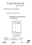
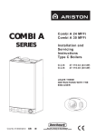
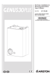
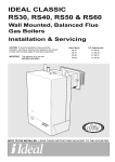
MINIMA MX2
COMBINATION BOILER
Heating and Instantaneous Domestic Hot Water
Fanned Flue system
Installation, Operating and Servicing Instructions
Manufactures N°
Model Type
Gas Council N°
200906827037.31
200906828037.31
MX2 24 FF NG
MX2 30 FF NG
47 - 980 - 28
47 - 980 - 29
GB
IE
c
These instructions are suitable for the Minima MX2 boilers :
Do not forget the Log Book!
Chaffoteaux & Maury supports Benchmark, the heating industry code to ensure the correct installation, commissioning and
servicing of domestic central heating systems.
To The Householder
Make sure you have a completed Log Book for your boiler. This provides a record of the commissioning of your boiler.
It contains important information about your particular installation that may be required by service engineers. The Log Book will
also provide contact details for the installer should you need guidance in the use of this appliance or if there are any problems.
As with your car, your boiler will work more reliably and efficiently if regularly serviced. We recommend an annual service
check. The service history of the appliance will be recorded on the Log Book.
In the unlikely event of any problems with your boiler or system you should first contact your installer. If your installer cannot
resolve the problem he should telephone our national service helpline.
A charge may be made if Chaffoteaux & Maury Service is called out to resolve a non-product related fault.
Your statutory rights are not affected.
To The Installer
As part of the commissioning of this appliance it is vital that the Log Book is completed and given to the Householder. Please
ensure that your customer is aware of the importance of keeping the Log Book safe as a record of the installation and the
appliance service history.
Please ensure that your customer is aware of the correct operation of the system, boiler and controls.
CUSTOMER CARE
Chaffoteaux & Maury, as a leading manufacturer of domestic and commercial water heating appliances is committed to
providing high quality products and a high quality after sales service. If it is necessary to contact an engineer, then telephone
the national warranty helpline 01494 539579.
Advice on installation or servicing can also be obtained by contacting the Chaffoteaux Customer Services Department at High
Wycombe.
CUSTOMER SERVICES DEPARTMENT
Tel:
01494 539579
Fax:
01494 459775
GUARANTEE
The manufacturer’s guarantee is for 12 months from the date of purchase. The guarantee is invalidated if the appliance is not
installed in accordance with the recommendations made herein or in a manner not approved by the manufacturer. To assist us
in providing you with an efficient after sales service, please return the guarantee registration card enclosed with the boiler
without delay.
CAUTION
In the United Kingdom, installation, start-up, adjustments and maintenance, must be performed by a competent person only, in
accordance with the current Gas Safety (Installation & Use) Regulations and the instructions provided.
In the Republic of Ireland, the installation and initial start up of the appliance must be carried out by a Competent Person in
accordance with the current edition of I.S.813 “Domestic Gas Installations”, the current Buidling Regulations, reference should
also be made to the current ETCI rules for electrical installation.
All CORGI registered installers carry a CORGI ID card, and have a registration number. Both should be recorded in
your boiler Log Book. You can check your installer is CORGI registered by calling CORGI direct on:- (01256) 372300.
Improper installation may cause damage or injury to individuals, animals and personal property for which the manufacturer will
not be held liable. To ensure efficient and safe operation it is recommended that the boiler is serviced annually by a competent
person.
If it is known that a fault exists on the appliance, it must not be used until the fault has been corrected by a competent person.
This instruction booklet is especially designed for appliances installed in the UK and the Republic of Ireland
2
Table of Contents
PAGE
CUSTOMER CARE
Guarantee
Statutory Requirements
Table of Contents
2
2
3
USER’S INSTRUCTIONS
1
2
3
4
5
6
7
8
9
10
11
12
12.1
12.2
12.3
12.4
12.5
13
14
15
16
17
18
19
20
21
CONTROL PANEL
HOW TO USE
MAINTENANCE
FLUE GAS SAFETY
GUARANTEE
PRACTICAL INFORMATION
INSTRUCTIONS FOR SETTING THE BUILT IN CLOCK
5
6
7
7
7
7
8
INSTALLER’S INSTRUCTION
9
DESCRIPTION
DIMENSIONS
HYDRAULIC DATA
INSTALLATION REQUIREMENTS
Reference Standards
Codes of Practice
Flue
Gas Supply
Electrical Supply
Showers
Flushing and Water Treatment
System Controls
Location
CONNECTING THE FLUE
Fitting the coaxial flue (Ø60/100 Horizontal)
Fitting the coaxial telescopic flue (Ø60/100 Horizontal)
Fitting the coaxial flue (Ø60/100 Vertical)
Fitting the 5” flue (Ø80/125)
Fitting the twin pipe (Ø80/80)
INSTALLING THE BOILER
ELECTRICAL CONNECTIONS
OPERATING
Pressurising
Settings
Burner gas output setting
FITTING THE CASING
COMPLETION
OPERATIONAL CHECKS
INSTRUCTING THE END USER
SETTING THE GAS PRESSURES / GAS TYPE CONVERSION
PARTICULAR CHARACTERISTICS
9
10
10
11
11
11
11
11
12
12
12
12
12
13
13
14
15
17
18
22
23
25
25
25
26
27
28
28
28
29
30
3
SERVICING INSTRUCTIONS
22
22.1
22.1.1
22.1.2
22.1.3
22.2
22.2.1
22.2.2
22.2.3
22.2.4
22.2.5
22.2.6
22.2.7
22.3
22.3.1
22.3.2
22.4
22.4.1
22.4.2
22.4.3
22.4.4
22.4.5
22.4.6
22.4.7
22.4.8
22.4.9
22.5
22.5.1
22.5.2
23
24
25
26
27
4
Replacement of Parts
To Gain General Access
Removing the front panel
Removing the side panels
Removing the control panel door
Access to the Combustion Chamber
Remove the combustion chamber front panel
Removing the burner manifold
Removing the electrodes
Removing the burner
Removing the main heat exchanger
Removing the air pressure switch
Removing the fan
Servicing and Removal of the Gas Valve
Removing the spark generator
Removing the gas valve
Access to the Water Circuit
Drain down
Removing the 3 way valve
Removing the float of the flow switch
Removing the pressure relief valve
Removing the secondary heat exchanger
Removing the pump
Removing the expansion vessel
Removing the overheat thermostat
Removing the heating temperature sensor (ntc)
Access to the Control System
Removing the P.C.B’s
Removing the fuses
INCORRECT OPERATION
FAULT FINDING
ELECTRICAL DIAGRAMS
SHORT SPARES LIST
TECHNICAL DATA
31
31
31
31
31
32
32
32
33
33
34
35
35
36
36
36
37
37
37
37
38
38
38
39
39
39
40
40
40
41
42
45
46
48
USER’S INSTRUCTIONS
1
Control Panel
23
24
c
Fig. 1
20
19
21
25
22
Control panel (Fig. 1)
Connecting bracket Taps shown in Open position
(Fig. 2)
19. - Pressure gauge
20. - On/off push button and power on indicator light
31 : Central heating flow isolating valve
21.- DHW water temperature setting and start button
32 : Domestic hot water outlet
22.- Central heating temperature setting and start button
33 : Gas service tap
23.- Heating temperature indicator and diagnostic indicator
34 : Cold water service tap
24.- Orange indicator - Burner ON
35 : Central heating return isolating valve
25.- Reset push button and red indicator lockout light
16 : Central heating pressure relief valve
16
35
31
Fig. 2
32
33
34
5
2
How to Use
Starting up (Fig. 2)
1. Ensure that the mains gas supply isolating tap is open and that the appliance is supplied with power.
2. Ensure that there is sufficient pressure in the heating circuit: the pressure gauge needle should be at a minimum of 1.2 bar
and a maximum of 1.7 bar when cold.
3. Ensure that the appliances gas inlet tap is open 33 (Fig. 2).
Your appliance is now ready to operate.
IMPORTANT!!
When the appliance is operated after a prolonged period of inactivity, the presence of air in the gas supply may hinder the first
attempts at igniting the gas, to correct this see Section 23 “Incorrect Operation”.
To obtain hot water and central heating :
To obtain hot water and central heating;
Press the On/Off button 20; it lights up green when power is supplied;
- turn the hot water temperature control knob 21
to allow water heating ignition when water is being drawn. This knob
allows you to adjust the hot water temperature. While hot water is being drawn, LEDs 23 light up two by two, displaying the
temperature of the water within the boiler,
- turn the central heating temperature control knob 22
to allow heating ignition. This button enables you to adjust the
water temperature in the central heating circuit according to seasonal requirements. LEDs 23
will display the
temperature of the water within the boilers primary circuit.
• Turn the control knob 22 :
- to Max in cold weather
- to Min in mild weather (by turning the knob too far, the Central Heating will swtich off)
Furthermore, if your home is fitted with a room thermostat, set it to the desired indoor temperature.
- the orange indicator light 24
lights up each time the burner operates
Stopping the central heating
- turn the central heating control knob 22 to the «off » position (fully anti-clockwise). The boiler then produces only hot water.
Stand-by mode
- turn the control knobs 21 and 22 to the «off »position (fully anti-clockwise), button 20 (Fig. 1) remains lit. The appliance
remains in stand-by mode unless the anti-frost device is activated.
Turn off the appliance*
- press button 20 , the indicator light turns off
- turn off the electricity supply to the water heater.
*NOTE: IN THIS STATE THE APPLIANCES ANTI-FROST DEVICE IS INACTIVE
NOTE:
In some circumstances, it is possible that the pipes (and possibly a radiator) heat up slightly after hot water is drawn. To
prevent this, simply close the central heating flow tap 31 (Fig. 2).
Remember to re-open it at the start of the heating season, when you switch the heating back on by rotating button 22 (Fig. 1)
or by turning the clock on.
6
3
Maintenance
Your boiler will work more reliably and efficiently if regularly serviced. We recommend an annual service check. The service
history of the appliance will be marked on the Log Book.
4
Flue Gas Safety
The boiler is fitted with a safety system which authorises operation of the burner. If this device does not detect movement in
the flue the boiler will shut down for safety reasons, and indicators 40, 60 and 80 flash 23 (Fig. 1).
IMPORTANT: this flue gas checking device must not be removed, or have untimely work carried out on it. If it needs to be
replaced, only original parts may be used.
5
Guarantee
The manufacturer`s guarantee is for 12 months from the date of purchase. The guarantee is voidable if the appliance is not
installed in accordance with the recommendations made herein or in a manner not approved by the manufacturer. To assist us
in providing you with an efficient after sales service, please return the guarantee registration card enclosed with the boiler without delay.
6
Practical Information
Pump anti-sticking device
With the boiler switched on (indicator light 20 lit), the circulation pump operates for 1 minute after the appliance has been out
of operation for more than 23 hours, to prevent the pump jamming.
Precautions to take in freezing conditions
We recommend that you contact your installer or After-Sales service, who will advise you of the measures to take according to
your circumstances.
Heating circuit
Take one of the following steps:
- 1) drain the circuit of the heating appliance
- 2) protect the heating appliance with an anti-freeze product.
- 3) allow your appliance to run at low load by setting the room thermostat to a low temperature (between 5 and 10°C).
- 4) leave the power to the boiler on. It is fitted with an anti-freeze device which activates the circulation pump, then the
burner.
- Alternatively the appliances central heating and hot water circuit can be drained. Please consult your installer or local
service agent.
7
7
Instruction For Setting the Built-in Clock (If Fitted)
1. General layout
The mechanical clock covers a 24 hour period. Each tappet
represents 15 minutes A (Fig. 4). An override switch is
located on the clock B (Fig 4).
2. To set the time
To set the time of day, grasp the outer edge of the dial and
turn slowly clockwise until the correct time is lined up with
the arrow C (Fig. 4).
3. To Set the "On" and "Off" times
The clock uses a 24hours system. e.g. 8 = 8.00 am and
18 = 6.00 pm "ON" periods are set by sliding all tappets
between the "ON" time and the "OFF" time to the outer edge
of the dial.The tappets remaining at the centre of the dial are
the "OFF" periods.
12
9
3
6
Fig. 3
4. For operation
Put the selector switch B to the
symbol to control the
central heating by the clock. Put the switch B to «I» to select
permanent operation or to «0» to turn the central heating off
permanently.
A
2
1
24
23
22
4
3
12
5
21
C
6
7
19
9
20
I
8
18
9
17
15
14
13
10
B
16
6
12
11
Fig. 4
8
INSTALLER’S INSTRUCTIONS
8
Description
1
2
3
14
4
9
5
11
10
6
1.- Steel chassis complete with expansion vessel
2.- Sealed chamber
3.- Flue hood with fan
4.- Main heat exchanger
5.- Combustion chamber
6.- Multi-gas burner assembly comprising ignition and
ionisation electrodes
7.- Gas valve assembly
8.- Pump with automatic air separator and automatic vent
9.- Overheat safety cut-out
10 - Return thermistor
11.- Flow thermistor
12.- Electrical box
13.- Hot water flow sensor
14.- Air pressure switch
15.- Ignitor
16.- Central heating pressure relief valve
17.- Three way valve
18.- Secondary heat exchanger
19. - Pressure gauge
20. - On/off push button and power on indicator light
8
12
21.- DHW temperature setting and start button
22.- Central heating temperature setting and start button
23.- Heating temperature indicator and fault diagnostic
indicator
24.- Orange indicator - Burner ON
25.- Reset push button and red indicator lock-out light
Fig. 5
18
17
7
16
13
15
Fig. 6
23
24
c
Fig.7
19
20
21
22
25
9
9
Dimensions
All dimensions in mm
18
289
15
18,5
21
Safety valve C/H
Heating flow
K
D.H.W. flow
L
Gas supply
M
Cold water inlet
N
Heating return
With packaging :
24 kW : 32 kg
30 kW : 33 kg
720
652
141
I
J
172,5
121,5
I
JKLM N
I
32
minimum 450
space
required
450mm
mini
pour entretien
296
54 54 54 54
440
390
J K L M N
Fig. 8
10
Hydraulic Data
.
Pump
head available
Pression disponible
mCE
6
Minimum
flow
rate (with
all heatingfermés)
thermostatic valves closed)
Débit mini
(robinets
thermostatiques
The graph (fig. 9) shows the development of the pressure
available in relation to flow on exit from the boiler. (Designed
temperature rise = 20oC).
5
4
2
To ensure correct operation, the minimum flow of the
appliance must be 300 l/h. (Thermostatic taps closed).
1
Capacity of the installation.
3
0
100
200
300
400
500
600
700
800
900
1000
1100
Pump head available at the outlet of the boiler
Pression
à froid
pour le circuit
chauffage
(en bar)
Central
heating
initial
pressure
Pf
1200
l/h
Fig. 9
40°C
- the average operating temperature in °C
1,7
1,6
- the static height, which is the difference in metres between
the highest point of the appliance and the expansion vessel
axis).
50°C
1,5
1,4
60°C
1,3
70°C
1,2
The minimum cold filling pressure of the appliance is 1 bar
(recommended pressure between 1.2 and 1.7 bar).
80°C
1,1
1,0
20
40
Maximum. volume of expansion vessel: 6 litres.
The volume of the expansion vessel in a pressurised
appliance varies according to:
1,9
1,8
The water heater is fitted with a pressurised expansion
vessel.
Pressure: 1 bar.
when cold (in bar)
2,0
60
80
100
120
140
160
180
200
220
240
260
Capacité maximale
de l'installation
(en litres)
System
capacity
chart
280
C litre
Fig. 10
10
The boiler is fitted with an automatic by-pass as standard.
The pressure of the expansion vessel should always be
greater than the static height (in metres) divided by 10.
11
Installation Requirements
Reference Standards
In the United Kingdom, the installation and initial start up of
the boiler must be by a CORGI Registered installer in
accordance with the installation standards curently in effect,
as well as with any and all local health and safety standards
i.e. CORGI.
In the Republic of Ireland the installation and initial start up of
the appliance must be carried out by a Competent Person in
accordance with the current edition of I.S.813 “Domestic Gas
Installations” and the current Building Regulations, reference
should also be made the the current ETCI rules for electrical
installation.
The installation of this appliance must be in accordance with
the relevant requirements of the Local
Building Regulations, the current I.E.E.
Wiring Regulations, the by-laws of the
local water authority, in Scotland, in
accordance with the Building Standards
I
(Scotland) Regulation and Health and
Safety document No. 635, “Elelectricity at
F
Work Regulations 1989” and in the
Republic of Ireland with the current edition
J
L
of I.S. 813 and the Local Building
Regulations (IE).
Flue
Detailed information on flue assembly can be found in Section
12 “Connecting the Flue”.
The boiler must be installed so that the flue terminal is
exposed to the free passage of external air at all times and
must not be installed in a place likely to cause nouisance. It
must not be allowed to discharge into another room or space
such as an outhouse or closed lean-to.
The terminal should be located with due regard for the
damage or discolouration that might occur to buildings in the
vicinity and consideration msut also be given to adjacent
boundaries.
In cold or humid weather, water vapour may condense on
Fig. 11
Q
Q
Q
D,E
B
G
N
C
A
I
M
N
H
H
M
K
C.O.S.H.H.
Materials used in the manufacture of this
appliance are non-hazardous and no
special precautions are required when
servicing.
Codes of Practice
Installation should also comply with the following British
Standards Codes of Practice:
leaving the flue terminal. The effect of such “pluming” must be
considered.
Treatment of water in domestic hot
water central heating systems
BS 5546:1990
Installation of hot water supplies for
domestic purposes
BS 5440-1:2000 Flues
BS 5440-2:2000 Air Supply
BS 5449:1990
Forced ciculation hot water systems
BS 6798:1987
Installation of gas fired hot water
boilers of rated input not exceeding
60kW
BS 6891:1989
Installation of low pressure gas pipe up
to 28mm
BS 7671:2001
IEE Wiring Regulations
BS 4814:1990
Specification for expansion vessels
BS 5482:1994
Installation of L.P.G.
The minimum acceptable clearances are shown below:
- A Directly below an opening, window, etc
300 mm
- B Above an opening, window, etc
300 mm
- C Horizontally to an opening, window, etc
300 mm
- D Below gutters, soils pipes or drain pipes
75 mm
- E Below eaves
200 mm
- F Below balconies or car port roof
200 mm
- G From a vertical drain pipe or soil pipe
150 mm
- H From an internal or external corner
300 mm
- I Above ground roof or balcony level
300 mm
- J From a surface facing the terminal
600 mm
- K From a terminal facing the terminal
1200 mm
- L From an opening in the car port into the dwelling 1200 mm
- M Vertically from a terminal on the same wall 1500 mm
- N Horizontally from a terminal on the same wall 300 mm
- Q Fixed by Ubbink Rolux 4 GM flue terminal
and in the Republic of Ireland in accordance with the following
codes of practice
NOTE: THE FLUE MUST NOT BE INSTALLED IN A PLACE LIKELY TO
CAUSE A NUISANCE.
BS 7593:1992
I.S. 813
Domestic Gas Installations
must be made to British Gas Document DM2, or advice sought
from CORGI.
Avoid installing the boiler where the air inlet can be polluted
by chemical products such as chlorine (swimming pool area),
or ammonia (hair-dresser), or alkalin products (launderette)
It may be necessary to protect the terminal with a guard.
Reference should be made to the Building Regulations for
guidance. Suitable guards may be obtained from the following
manufacturer:
Quinnel Barret & Quinnel Wireworks
Old Kent Road
London SE15 1NL
Tel: 020 7639 1357
11
11
Installation Requirements (continued)
Ventilation
The room in which the boiler is installed does not require specific
ventilation. If it is installed in a cupboard or compartment
permanent ventilation is not required for cooling purposes.
Fernox Manufacturing
Britannica Works
Clavering
Essex
CB11 4QZ
Tel: 01799 550811
Gas Supply
The gas installation and soundness testing must be in
accordance with the requirements of BS 6891.The boiler
requires a 22 mm supply. Ensure that the pipe size is
adequate for demand including other gas appliances on the
same supply.
Electrical Supply
The appliance requires an earthed 230V - 50 Hz supply and
must be in accordance with current I.E.E. It must also be
possible to be able to completely isolate the appliance
electrically. Connection should be via a 3 amp fused doublepole isolating switch with contact separation of at least 3 mm
on both poles. Alternatively, a fused 3 Amp. 3 pin plug and
unswitched socket may be used, provided it is not used in a
room containing a bath or shower. It should only supply the
appliance.
The boiler is suitable for sealed systems only. The maximum
working pressure for the appliance is 10 bar. All fittings and
pipework connected to the appliance should be of the same
standard. If there is a possibility of the incoming mains
pressure exceeding 10 bar, particularly at night, then a
suitable pressure limiting valve must be fitted.
The boiler is designed to provide hot water on demand to
multiple outlets within the property. If there is a requirement
for greater demands, for example if the property has several
bathrooms and cloakrooms, a vented or unvented hot water
storage system may be used.
Showers
Any shower valves used with the appliance should be of a
thermostatic or pressure balanced type. Refer to the shower
manufacturer for performance guidance and suitability.
Flushing and Water Treatment
The performance of the appliance could be impaired by
system debris or the effects of corrosion. The system must
be flushed thoroughly to remove metal filings, solder,
machining oils and other fluxes and greases before
connecting the boiler. If it is an existing system, an
appropriate flushing and descaling agent should be used.
Refer to BS 7593 (1992) for guidance. For more information
on the use of corrosion inhibitors, flushing and descaling
agents, advice can be sought from the manufacturers of
water treatment products such as:
Betz Dearborn Ltd
Foundry Lane
Widnes
Cheshire
WA8 8UD
Tel: 0151 424 5351
12
System Controls
The boiler is electrically controlled and is suitable for most
modern electronic time and temperature controls. The
addition of such external controls can be beneficial to the
efficient operation of the system. The boiler connections for
external controls are 24V and so only controls of 24V or that
have voltage free contacts should be used.
Location
The boiler can be installed on any suitable internal wall.
Provision must be made to allow the correct routing of the flue
and siting of the terminal to allow the safe and efficient
removal of the flue products. A compartment or cupboard may
be used provided that it has been purpose-built or modified for
the purpose. It is not necessary to provide permanent
ventilation for cooling purposes. Detailed recommendations
are given in BS 5440 pt 2. If it is proposed that it is installed in
a timber framed building then reference
Where a room sealed appliance is installed in a room
containing a bath or shower, the appliance and any
electrical switch or appliance control, utilising mains
electricity should be situated specifically in accordance
with current IEE Wiring Regulations.
For unusual locations, special procedures may be necessary.
BS 6798:1987 gives detailed guidance on this aspect.
Connecting the Flue
12
The boiler must only be installed with a flue supplied by the boiler manufacturer.
These kits are supplied separately to the appliance in order to respond to different installation solutions. For more information
with regard to the inlet/outlet accessories consult the flue brochure and the following instructions.. The boiler is predisposed for
the connection to a twin flow concentric gas intake and exhaust duct system.
WARNING!!
The exhaust gas ducts should not be in contact with or close to
inflammable material and should not pass through building structures or
walls made of inflammable material.
When replacing an old appliance, the flue must be changed.
IMPORTANT!!
Ensure that the flue is not blocked.
Ensure that the exhaust gas ducts do not
have leaks
Ø 60/100 mm
Fig. 12
12.1 Fitting the coaxial flue (Ø 60/100 Horizontal)
CONTENTS:
1X SILICONE O-RING (60mm)
1X ELBOW (90 )
2X WALL SEALS (INTERNAL & EXTERNAL)
1X ALUMINIUM FLUE PIPE INCLUDING TERMINAL (1 METRE - 60/100)
2X FLUE CLAMPS
4X SCREWS
2X SEALS
O
Once the boiler has been positioned on the wall, insert the elbow into the socket and rotate to the required position.
NOTE:
It is
o
possible to rotate the elbow 360 on its vertical axis.
Using the flue clamps, seals and screws supplied (Fig 12) secure the elbow to the boiler.
The 1 metre horizontal flue kit (705958) supplied is suitable for an exact X dimension of 823mm, and the 750mm horizontal
flue kit (705785) is suitable for an exact X dimension of 573mm.
Measure the distance from the face of the external wall to the face of the flue elbow (X - Fig 12), add 22 mm to this
measurement, you now have the total length of flue required (including the terminal), this figure must now be subtracted from
860mm, you now have the total amount to be cut from the plain end of the flue.
Cut the flue to the required length ensuring that the distance between the inner and the outer flue is maintained (Fig 13).
13
Connecting the Flue (continued)
12
e.g.
X = 508mm + 22mm = 530mm
860 - 530 = 330mm (Length to be cut from the plain end of the flue).
Once cut to the required length, ensure that the flue is free from burrs and reassemble the flue. If fitting the flue from inside of
the building attach the grey outer wall seal to the flue terminal and push through the flue through the hole, once the wall seal
has passed through the hole, pull the flue back until the seal is flush with the wall. Alternatively, the flue can be installed from
outside of the building, the grey outer seal being fitted last.
25 mm
25 mm
25
Fig 13
mm
WARNING!!
Consult the table on Page 19, to see if a restrictor is
required for the type of flue system being used. Should it
be necessary to fit the restrictor, it must be fitted as shown
in Fig. 14.
Coaxial
Fig 14
12.2 Fitting the telescopic flue (Ø 60/100 Horizontal)
CONTENTS:
1X SILICONE O-RING (60mm)
1X ELBOW (90 )
2X WALL SEALS (INTERNAL & EXTERNAL)
1X ALUMINIUM FLUE PIPE INCLUDING TERMINAL (TELESCOPIC - 60/100)
2X FLUE CLAMPS
8X SCREWS
2X SEALS
O
The telscopic flue is suitable for use with an exact minimum X dimension of 270mm and an exact maximum X dimension
470mm.
IMPORTANT!!
Do not extend the telescopic flue to an X dimension of more than 470mm. If longer lengths are required use
extension pieces as necessary. Under no circumstances must the flue be cut.
o
The wall must then be made good around the flue (ensuring a fall of 1 is maintained away from the boiler to the flue terminal).
Once made good, place the inner (white) wall seal over the flue and push up to the wall, secure the flue to the elbow by using
the clamp supplied.
For each additional 90o elbow 1 metre must be removed from the total flue length (maximum 4 metres including the 1st elbow).
For each additional 45o elbow 0.5 metre must be subtracted from the total flue length (Fig 16).
14
12
Connecting the Flue (continued)
12.3 Fitting the coaxial flue (Ø 60/100 Vertical)
CONTENTS:
1X SILICONE O-RING (60mm)
1X CONICAL ADAPTOR (60/100mm)
1X VERTICAL FLUE KIT (80/125mm)
3X SCREWS
The vertical flue kit is supplied with a specially designed weather proof terminal fitted, it can be used either with a flat roof or a
pitched roof. (see Figs. 17 and 18).
The Vertical flue kits maximum and minimum useable lengths with both flat and pitched roof flashings are indicated in Figs. 17
and 18 also).
NOTE:
Fig 15
MAX LENGTH = a+a+a +
b+b = a+a+a+0.5+0.5
COMBINED LENGTH NOT
TO EXCEED 3m
Fig 16
Before proceeding to fit the flue, ensure that the maximum flue length has not been exceeded and that all elbows and bends
have been taken into consideration, the maximum flue length is 4 metres, for each additional 90o elbow 1 metre must be
subtracted from the total flue length, and for each 45o 0.5 metres must be subtracted from the total flue length (the offset and
height of 2 x 45o bends can be seen in Fig. 19).
Mark the position of the flue hole in the ceiling and/or roof (see Fig. 17 for distance from wall to the centre of the flue).
Cut a 120mm diameter hole through the ceiling and/or roof and fit the flashing plate to the roof.
Should it be necessary to cut the flue DO NOT cut the outer white ar inlet tube, cut the aluminium exhaust flue 6mm longer
than the outer white air tube when used at minimum length. DO NOT cut more that 250mm from the inner aluminium exhaust
flue.
To connect the vertical flue kit directly to the boiler, place the adaptor (see Fig. 15) (supplied with vertical flue kit) onto the
exhaust manifold and secure with the clamp, the vertical flue kit must then be inserted through the roof flashing, this will
ensure that the correct clearance above the roof is provided as the terminal is a fixed height.
Should extensions be required, they are available in 1 metre (Part No. 705786), 500mm (Part No. 705790) and 160mm
lengths (Part No. 705812), they must be connected directly to the boiler and secured with the clamp supplied before
connecting the adaptor to allow the vertical flue kit to be fitted. In the event that extension pieces need to be shortened, they
15
12
Connecting the Flue (continued)
must only be cut at the male end and it must be ensured that the distance between the inner and outer flue are kept (Fig. 13).
When utilising the vertical flue system, action must be taken to ensure that the flue is supported adequately to prevent the
weight being transferred to the appliance flue connection.
When the flue passes through a ceiling or wooden floor, there must be an air gap of 25mm between any part of the flue system
and any combustible material. The use of a ceiling plate will facilitate this. Also when the flue passes from one room to
another a fire stop must be fitted to prevent the passage of smoke or fire, irrespective of the structural material through which
the flue passes.
Fig. 17
Fig. 18
Minimum offset distance when using 2x 45o bends
Fig. 19
16
12
Connecting the Flue (continued)
12.4 Fitting the 5” flue (Ø 80 / 125)
Once the boiler has been positioned on the wall, it is necessary to insert the Ø80/125 adaptor into the boiler flue socket.
Place the Ø 60mm insert (Fig. 20) into the boilers exhaust connection;
Fit the grey seal over the boilers flue connection and ensuring all lip seals are fitted correctly push the adaptor onto the boilers
flue connection, checking that the seal is fitted correctly over the adaptor;
To secure the adaptor, use the clamp and screws provided (Fig. 20).
To fit extensions or elbows it is first necessary to ensure that the red lip seal is fitted correctly into the inner flue, once verified,
it is simply necessary to push them together, no clamps are necessary to secure the flue components.
NOTE: WHERE THE TOTAL LENGTH OF FLUE IS GREATER THAN 5 METRES, THE CONDENSATE DRAIN ON THE ADAPTOR MUST BE UTILISED.
Minimum offset distance when using 2x 45o bends
(Ø80/125 Flue)
Fig. 20
Fig. 21
17
12
Connecting the Flue (continued)
12.5 Fitting the twin pipe (Ø80/80)
Where it is not possible to terminate the flue within the distance permitted for coaxial flues, the twin flue pipe can be used by
fitting a special adaptor to the flue connector and using the aperture for the air intake located on top of the combustion
chamber.
Considerations necessary for twin flue installation;
It is most important to avoid any possible condense formation entering the appliance.
Condense may form when the 24kW boiler has an exhaust pipe longer than 5.5m and on the 30kW when the exhaust pipe is
longer than 7.5m. If this is the case, there are two options;
1) Where condense will form but can be negated with insulated flue, install the insulated flue ensuring it has a fall of 5mm in
every metre away from the boiler.
2) The exhaust flue will have a fall of 3o back to the boiler and a suitable trap will be fitted on the exhaust as close to the boiler
as possible, condense will then be suitably disposed of.
Where the flue runs through cold spots, i.e. loft areas, condense is likely to be formed, therefore in such cases a fall back to
the boiler and a trap is required.
200
135
123,5
25
107
200
If the two elbows are to be
run in the same lateral
direction and if you need to
reduce the required space
above the boiler, the
minimum 230 mm
measurement can be
reduced by carefully cutting
the elbow below the air inlet
by 25 mm
230 MIN *
132
123,5
Fig. 22
Always ensure that the flue is adequately supported, avoiding low points. (MTS supply suitable clamps as Part No. 705778).
To utilise the air intake it is necessary to:
1) Take the air intake cover off
2) Assemble the flange on the header supplied with the boiler
3) Insert the restrictor if necessary, on the tube or the elbow
4) Insert the header on the tube or the elbow up until the lower stop
(you do not have to use the washer).
5) Insert the elbow/header in the boiler air intake hole and fasten it with screws
The twin flue pipes can be fitted with or without additional elbows and need no clamps, simply ensure that the red o-ring is
inserted in the female end of the flue pipe and push the extension piece fully into the previous section of flue pipe or elbow,
check that the o-ring is not dislodged when assembling the flue.
Twin pipe can also be converted back to Coaxial flue to enable vertical termination with a coaxial kit by using the pipe bridge
(Twin - Coaxial Adaptor - Part No. 705767). When running the twin flue pipe vertically, a condense trap must always be used
on the exhaust pipe.
It is not recommended that the pipe bridge for horizontal termination, however in the unlikely event that this proves to be a
necessity it is extremely important that the entire flue has a fall of 3o back to the boiler, is suitably trapped and where the
18
12
Connecting the Flue (continued)
60mm inner flue of the concentric terminal connects to the pipe bridge, this point must be adequately sealed with silicone
sealant to avoid condense leakage at this point.
NOTE: Vertical twin flue installations must have a trap on the exhaust. MTS supply a suitable condense trap Part No. 705774
and recommend that this be used in the event that the flue may not form condense.
When siting the twin flue pipe, the air intake and exhaust terminals must terminate on the same wall, the centres of the
terminals must be a minimum of 280 mm apart and the air intake must not be sited above the exhaust terminal (refer to Fig.
25). The air intake pipe can be run horizontally, however, the terminal and the final 1 metre of flue must be installed with a fall
away from the boiler to avoid rain ingress.
It is also strongly recommended that the air intake pipe run be constructed of insulated pipe to prevent condense forming on
the outside of the tube.
The maximum permissible flue length for twin flue is dependent on the type of run used.
For flue runs with the intake and exhaust pipes under the same atmospheric conditions (TYPE 4) the maximum length is 24
metres (24kW) and 30 metres (30kW), for runs with the terminals under different atmospheric conditions (TYPE 5) the exhaust
terminal must extend 0.5 metres above the ridge of the roof (this is not obligatory if the exhaust and air intake pipes are
located on the same side of the building). For TYPE 5 also, the maximum permissible combined length is 45 metres (24kW)
and 60 metres (30kW).
The maximum length is reached by combining the total lengths of both the air intake and exhaust pipes. Therefore a
maximum length of 45 metres for
example, will allow a flue run of 22.5 metres for the air intake and 22.5 metres for the
o
exhaust pipes, also for each 90 elbow 1.3 metres must be subtracted from the total length and for each 45o elbow 1 metre
must be subtracted from the total flue length.
Some of the acceptable flue configurations are detailed page 21.
For further information relating to flue runs not illustrated, please contact the Technical Department on 01494 539579.
WARNING!!
Consult the table on Page 20, to see if a restrictor is
required for the type of flue system being used.
Should it be necessary to fit the restrictor, it must be
fitted as illustrated in Fig. 23.
Twin flue
ø 100
Fig. 23
In the event that twin flue pipes are used, and the
boiler has a side clearance of less than 60mm from
the wall, it is necessary to cut a larger diameter
hole for the flue pipe, this should be ø10 cm, this
will then allow for easier assembly of the air intake
elbow and the tube outside the wall (see Fig. 24).
60 mm
Fig. 24
19
Connecting the Flue (continued)
12
Concentric outlet
60/100
24 kW
(Type 1, Type 2, Type 3)
30 kW
(Type 1, Type 2, Type 3)
Restrictor
ø 88.5
L min. = 0.3 m
L max. = 1 m
L min. = 0.3 m
L max. = 1 m
Without restrictor
L min. = 1 m
L max. = 4 m
L min. = 1 m
L max. = 4 m
Max. length
4m
/
4m
/
L = total length of gas intake and exhaust ducts.
Twin flue outlet
24 kW
Type 4
80/80
Type 5
80/80
Restrictor
ø 41
L min. > 0 m
L max. = 2.5 m
L min. > 0 m
L max. = 10 m
Restrictor
ø 46
L min. > 2.5 m
L max. = 12 m
L min. > 10 m
L max. = 29 m
Restrictor
ø 51
L min. > 12 m
L max. = 19 m
L max. > 29 m
L max. = 35 m
Without
restrictor
L max. > 19 m
L max. = 24 m
L max. > 35 m
L max. = 45 m
Without
restrictor
L min. > 12 m
L max. = 30 m
L max. > 30 m
L max. = 60 m
Without
restrictor
L max. > 19 m
L max. = 24 m
L max. > 35 m
L max. = 45 m
Air intake length 1 m.
L = total length of gas intake and exhaust ducts.
If the exhaust gas duct length is longer than 5.5 m, you will need a condensate drain
Twin flue outlet
30 kW
Type 4
80/80
Type 5
80/80
Restrictor
ø 44
L min. > 0 m
L max. = 3 m
L min. > 0 m
L max. = 11.5 m
Restrictor
ø 50
L min. > 3 m
L max. = 12 m
L min. > 11.5 m
L max. = 30 m
Air intake length 1 m.
L = total length of gas intake and exhaust ducts.
If the exhaust gas duct length is longer than 7.5 m, you will need a condensate drain
For coaxial systems, the maximum development value L, mentioned in the table above also takes into accout an elbow.
For twin flue isystems the maximum development value L, mentioned in the table includes the exhaust gas/air intake terminal.
Type 5 outlets should respect the following instructions:
1- Keep the same ø 80 mm for the gas intakes and exhaust gas ducts.
2- If you need to insert elbows in the gas intake and exhaust gas ducts, you should consider for each one the equivalent length
to be included in the calculation of developed length.
3- The exhaust gas duct should jut above the roof by at least 0.5 m.
4- The intake and exhaust gas ducts in Type 5 must be installed on the same wall, or where the exhaust is vertical and the air
intake horizontal, the terminals must be on the same side of the building.
NOTE: UNDER
SOME CIRCUMSTANCES, CONDENSE MAY FORM AT THE EXHAUST TERMINAL, SPECIAL ATTENTION MUST BE PAID WITH REGARD
TO POSSIBLE CONDENSE DRIPPING FROM THE TERMINAL
20
12
Connecting the Flue (continued)
TYPE 1
TYPE 4
TYPE 3
TYPE 2
TYPE 5
NOTE: DRAWINGS ARE INDICATIVE OF FLUEING OPTIONS ONLY.
AIR INTAKE MUST NOT BE
FITTED ABOVE THE EXHAUST
AIR INTAKE
EXHAUST
AIR INTAKE
Fig. 25
21
13
Installing the Boiler
- place the template in the selected position on the wall
- fit the hanging bracket
- Install the gas and water pipes and the electrical connection to the locations shown on the fitting template
- Drill the hole for the flue
- unscrew the clamp locking bolt A, which secures the front panel (Fig. 26)
- remove the front panel from the boiler (1 & 2 Fig. 26)
- offer the water heater up to its bracket and allow it to drop into position while pressing on it (Fig. 27)
- fit the connectors and taps (Fig. 2, page 5)
- connect the water and gas pipes to the boiler, with the various seals
- connect the flue to the boiler (for more detailed instructions on this see Section 12 Connecting the Flue).
The safety valve discharge pipe must be run to outside and discharge in a place not likely to cause nuisance or injury.
Cleaning the central heating system
Once the central heating system has been connected, it is essential to clean the appliance with an appropriate product (dispersing agent), the boiler and system must be filled and flushed cold, the system must be refilled and heated to temperature
and flushed again, to remove filings, solder, and various factory oils and greases. The system must then be refilled again and
inhibited.
Do not use any solvent or aromatic agent.
A
1
2
Fig. 26
Fig. 27
37
Fig. 28
22
14
Electrical Connections
IMPORTANT!!
Connection should be via a 3 amp fused
double-pole isolating switch with contact
separation of at least 3 mm on both
poles. Alternatively, a fused 3 Amp. 3 pin
plug and unswitched socket may be
used, provided it is not used in a room
containing a bath or shower. It should
only supply the appliance.
B
P
P
Fig. 29
C
The 240 V and earth connection are made by using the lead provided at J1 (Fig. 30).
IMPORTANT!!
If the supply cable is damaged, it must be replaced.
Room thermostat connection
Before it leaves the factory, the boiler is set to operate without a room thermostat: a shunt S is placed on connector D.
The room thermostat connection is made on this connector
- Lower the electronic control unit by releasing the side locking pins P (Fig. 29), to gain access to the reverse side
- Remove screws B and remove cover C (Fig. 29).
The room thermostat connection can then be accessed.
- Remove connector D and shunt S.
- Connect the thermostat wires to the connector (D).
- Reconnect connector D.
J1
T
E
J1
Cable 240 V
D
J12
Fig. 30
S
J12
23
14
Electrical Connections (continued)
- If a remote time clock is to be fitted, using a volt-free switching time clock, connect the switching wires from the time
clock following points above (see also Diagram B Fig. 31).
- If using an external time clock and room thermostat, these must be connected in series as above (see also Diagram
C Fig. 31).
Live and Neutral connections to operate the clock motor must be taken from a suitable source.
Connector J12 (Fig. 30), is provided for connecting an optional integral time clock or programmer, for fitting instructions,
please refer to those provided with the clock.
Connector D
Connector D
Connector D
Fig. 31
24
15
Operating
- Set the system pressure, close filling taps 36, 37 and
remove filling loop 38.
- Check for leaks.
- Manually check pump is free to turn
PRESSURISING (Fig. 32)
Domestic Hot Water Circuit:
- open the cold water tap 34
- open all hot water taps until water flows
Central Heating Circuit:
- Open flow and return valves on the boiler 31 and 35
- Loosen the cap on the automatic air vent
- Open filling taps 36 and 37, and vent the radiators.
Gas circuit
- open the gas tap 33
- purge the gas circuit
- test the gas circuit for soundness
16
33
35
34
31
Fig. 32
37
38
36
SETTINGS
The boiler is supplied with all the dip switches OFF (Fig. 33) and the potentiometers turned fully anti-clockwise. It is possible
to adjust these settings as required.
In this case, it is necessary to access the electronic control unit.
Switch the power on, remove the casing and open the control unit by pressing the two side locking pins P (Fig. 29). The
setting buttons are on the circuit board behind the blanking cover E (Fig. 30)
- A1 allows the Heating Anti-cycle Timing (HAT) to be set to 30 seconds or 3 minutes
HAT:
Prevents the burner from relighting for the time set (30 seconds or 3 minutes) once the central heating circuit
has reached the temperature set on the Central Heating temperature knob 22 (Fig. 1).
- A2 reserved
- A3 to fix the heating temperature setting to 40°C whatever the setting of the Central heating temperature knob 22 (Fig. 1)
- A4 enables operation either in modulating heating mode, or on/off mode
- B1 reserved
- B2 reserved
- B3 allows the hot water flow switch timing to be adjusted to 0 or 1.5 seconds
- B4 reserved
Note: after a power cut-out or board reset, the HAT is cancelled for 3 minutes.
- P1: potentiometer to range rate the Central heating output (see table on page 26)
- P2: potentiometer enabling soft-light ignition (factory set at: 12.7 kW - MX2 24 FF and 16 kW - MX2 30 FF)
- P3: reserved
Once adjustments have been made, replace the blanking cover E (Fig. 30), close the control unit cover and refit the casing.
25
Operating (continued)
15
P2
P1
P3
ON
OFF
Célectic
B4
Tempo Débistat
Sanitaire
1,5 sec
Tempo Débistat
Sanitaire
0 sec
Domestic
hot water
flow switch
time 1.5 sec. Domestic
hot water
flow switch
time 0 sec.
B3
B2
B1
Consigne
chauffage
variable
de 35
35 to
à 85
°C
Variable
heating
setting
between
85°C
Pompe Petite Vitesse
A2
Pompe Grande Vitesse
Anticycle30
30secs
s
Anti-cycle
A1
ON
Fonctionnement
Modulant
Modulating
operation
On/Off
operation TOR
Fonctionnement
Consigne
chauffage
Heating
setting
40 °C à 40 °C
A4
A3
Anticycle33min
min
Anti-cycle
OFF
Fig. 33
Factory setting
Burner gas output setting
The values shown in the tables below are given for information purposes for a nominal gas distribution pressure, to allow any
adjustments to the water heater heating output according to the requirements of the system.
They cannot be used to calculate the precise regulated output of the boiler.
MX2 24
Gas :
G20
Power Burner
(kW)
Pressure
(mbar)
26
MX2 30
PROPANE
BUTANE
Gas :
Burner
Pressure
(mbar)
Burner
Pressure
(mbar)
Power Burner
(kW)
Pressure
(mbar)
G20
PROPANE
BUTANE
Burner
Pressure
(mbar)
Burner
Pressure
(mbar)
4.1
10
1.8
6.7
4.7
12
1.5
5.8
12.7
3.3
11.1
8.1
16
3.5
10.7
7.8
16
5.3
17.2
12.9
20
5.9
16.7
12.4
20
8.2
25.8
19.5
25
9.3
25.6
19.0
24
11.4
35.2
26.8
30
13.0
35.9
26.5
16
Fitting the Casing
Fitting the casing
Remove the protective film on the casing:
- offer the casing up (Fig. 34)
- engage hooks N on the casing in notches R (operation 1)
- fit the top of the panel in place
- close the panel mounting clamps (Fig. 35)
- screw in the clamp locking bolt A
Note: it is essential to refit the locking bolt A
1
A
N
R
Fig. 34
Fig. 35
27
17
Completion
For the Republic of Ireland it is necessary to complete a “Declaration of Conformity” to indicate compliance to I.S. 813. An
example of this is given in the current edtion of I.S. 813. In addition to this it is necessary to complete the
Log Book.
18
Operational Checks
1. The flue system must be visibly checked for soundness.
2. On Central Heating allow the system to warm up and manipulate the Central Heating temperature control knob, check the
burner modulates up and down between the high and low settings.
3. Range rate the thermal power for Central Heating, as detailed in Section 20 (Setting the gas pressures).
4. Run the Domestic Hot Water, manipulate the Domestic Hot Water temperature control knob to check the burner modulates
up and down between the high and low settings. Regulate the hot water flow rate to achieve the desired temperature rise.
5. Balance the Central Heating system until all return temperatures are correct and equal.
6. Turn the ON/OFF button OFF, disconnect the pressure Gauge, retighten screw and relight boiler.
7. Re-examine Central Heating, Domestic Hot Water and Cold Water supplies for soundness.
8. Check the appearance of the gas flame to assess the adequacy of the combustion air supply.
9. If external controls have been disconnected, reconnect and test.
10. Refit boiler casing.
19
Instructing the End User
1. Hand over this copy of the Installation, Servicing and Operating instructions supplied with the appliance, and explain how to
use the timeclock and room thermostat if fitted.
2. Show the End User how to switch the appliance off quickly, and indicate the position of the electric supply isolator.
3. Inform the End User of the location of all drains, isolating valves and air vents.
4. Explain how to turn the appliance off for both short and long periods and advise on the precautions necessary to prevent
damage in the event that the appliance is inoperative when freezing conditions occur.
5. Finally advise the End User that, for continued safe and efficient operation, the appliance must be serviced by a competent
person at least once a year.
28
20
Setting the Gas Pressures / Gas Type Conversion
When adapting to a gas different from the one for which the boiler is equipped, you should replace the parts delivered with the
conversion kit, and make the gas valve adjustments as described below:
Fig. 36
Setting the minimum and the maximum power of the boiler
Check that the supply pressure and dynamic pressure to the gas valve is a
minimum of 20 mbar for natural gas. To do this, loosen the screw “A”.
Fit the pipe of the pressure gauge to the inlet pressure connection of the gas valve
“B” check for the correct standing pressure, then operate the appliance and check
for the correct working pressure.
When you have completed this operation, replace the screw “A” securely into its
housing to seal off the gas (check for tightness).
To check the pressure supplied by the gas valve to the burner, loosen the screw
“C”. Fit the pipe of the pressure gauge to the pressure outlet test point of the gas
valve “D”.
Disconnect the compensation pipe “D1” either from the gas valve or from the
sealed chamber.
Turn the boiler on, and ensure that the hot water temperature control knob is set to
maximum. Turn on the boiler by running a hot water tap.
Adjust the 10mm nut “E” on the modureg to set the maximum gas pressure, turn
the nut clockwise to increase and anti clockwise to decrease the pressure until the
required pressure is achieved (see MAXIMUM BURNER PRESSURE TABLE page 30).
To set the minimum power, disconnect a supply terminal “F1” from the modureg
and adjust screw “F” (ensure the 10mm nut is held in position). Turn the screw
clockwise to increase the gas pressure and counter-clockwise to decrease the gas
pressure (displayed on the pressure gauge) corresponding to the minimum power
(see MINIMUM BURNER PRESSURE TABLE page 30).
When you have completed the above operations, turn off the hot water tap, reconnect the supply terminal to the modureg on the gas valve and replace the cap
on the screw of the modureg.
B
A
Fig. 37
D1
C
C
D
D
Setting the maximum heating circuit power
To set the maximum heating circuit power, turn the boiler on and turn the Central
Heating temperature control knob to maximum, ensuring all extermal controls are
calling for heat.
Remove the inspection panel of the P.C.B. and fit a small cross-head screwdriver
in to the right hand potentiometer (see page 26). Turn clockwise to increase the
pressure or counter-clockwise to reduce the pressure. Adjust the setting to the
required heating pressure value (displayed on the pressure gauge), as indicated in
the tables shown on page 30.
Turn off the boiler by placing the main switch to the "OFF" position.
Fig. 38
E
E
Note : when adjusting the minimum output in G30/G31 on 24 FF boilers, you
should place the metal plate supplied with the boiler and the gas changing
kit on the manifold. (Fig. 40 page 30)
Important: do not forget to remove this plate once the adjustment has been
completed. (the tab prevents the boiler from being reassembled).
Adjusting the ignition output
The potentiometer P2 (Fig. 33) on the PCB permits this adjustment (12.7 kW MX2 24 FF and 16 kW - MX2 30 FF) (see Settings on page 25).
Disconnect the detection electrode (see section 22.2.3 - Fig. 50).
Start the boiler and during the ignition sequence adjust the left hand potentiometer
until the gas pressure reads the required gas pressure as per the table below.
Once the gas pressure is set turn off the boiler and re-connect the detection
electrode.
NB.: It may be necessary to reset the flame failure reset a number of times during
this operation.
Fig. 39
F
F
Remove the pipe from the test point and tighten the screw “C” to the pressure
test point in order to seal off the gas. Carefully check the pressure test points for
gas leaks (valve inlet and outlet), reconnect the compensation pipe D1.
F1
IMPORTANT!
Whenever you disassemble and reassemble the gas connections, always check
for leaks using a leak detection fluid.
NOTE: ALWAYS CHECK THE GAS RATES FOLLOWING ADJUSTMENT.
29
20
Setting the Gas Pressures (continued)
Maximum Burner Pressure (mbar)
mbar
G 20
G 30
G 31
24 kW FF
11.4
26.8
35.2
30 kW FF
13
26.5
35.9
Minimum Burner Pressure (mbar)
Fig. 40
21
Particular Characteristics
Flow switch float assembly direction
By-pass valve assembly direction
30
mbar
G 20
G 30
G 31
24 kW FF
1.8
4.7
6.7
30 kW FF
1.5
4.1
5.8
SERVICING INSTRUCTIONS
A
To ensure efficient safe operation, it is recommended that the
boiler is serviced annually by a competent person.
Before starting any servicing work, ensure both the gas and
electrical supplies to the boiler are isolated and the boiler is
cool.
Before and after servicing, a combustion analysis should be
made via the flue sampling point.
After servicing, preliminary electrical system checks must be
carried out to ensure electrical safety (i.e. polarity, earth
continuity, resistance to earth and short circuit).
22
Replacement of Parts
The life of individual components vary and they will need
servicing or replacing as and when faults develop.
The fault finding sequence chart in Section 24 will help to locate
which component is the cause of any malfunction, and
instructions for removal, inspection and replacement of the
individual parts are given in the following pages.
Fig. 41
22.1 To Gain General Access
All testing and maintenance operations on the boiler
require the control panel to be lowered. This will also
require the removal of the casing.
Fig. 42
22.1.1 Removing the front panel :
1. Unlock the two clamps locking A (see Figs. 41 & 42);
2. Remove the front panel from the rest of the
casing (see Fig. 43).
22.1.2 Removing the side panels :
1. Remove the front panel;
2. Remove the screws B lift toward at the base and
then lift off the locating lugs (see Fig. 44).
Fig. 43
22.1.3 Lowering the control panel :
1. Remove the front panel;
2. Unlock the two clamps locking and pivot the
electrical box downward (see Fig. 45).
B
Fig. 45
Fig. 44
31
22.2 Access to the Combustion Chamber
22.2.1 Removing the combustion chamber front panel
1. Carry out step 22.1.1;
2. Unscrew five self tapping screws “D” to release
the combustion chamber front panel and lift clear
(for the 24kW see Fig. 46a, for the 30kW see Fig. 46b);
3. Reassemble in reverse order.
22.2.2 Removing the burner manifold
1. Carry out step 22.1.1 and 22.2.1;
2. Unscrew the nut between manifold and gas pipe
(see Fig. 47).
3. Unscrew the 4 screws “E” securing the burner
and lift clear (see Fig. 48).
4. Reassemble in reverse order
24 kW
Fig. 47
D
Fig. 48
E
Fig. 46a
30 kW
D
Fig. 46b
Fig. 46c
32
22.2.3 Removing the electrodes
22.2.4 Removing the burner
1. Carry out steps 22.1.1 and 22.2.1;
2. Unscrew the self tapping screws (see Fig. 49);
3. Disconnect the lead from the wiring loom (see Fig. 50);
4. Remove the electrodes (see Fig. 51);
5. Reassemble in reverse order.
1. Carry out steps 22.2.1, 22.2.1 and 22.2.2;
2. Remove the two self tapping screws “F” securing the
burner (see Fig. 48);
3. Pull the burner out of the combustion chamber (see
Fig. 53);
4. Remove the self tapping screws securing the
electrodes (see Fig. 54)
5. Reassemble in reverse order;
6. Carry out combustion tests using the test point on
the turret
Fig. 49
F
Fig. 52
Fig. 53
Fig. 50
Fig. 54
Fig. 51
33
22.2.5 Removing the main heat exchanger
1. Carry out step 22.1.1, 22.2.1 and 22.2.2;
2. Drain the boiler (only heating circuit);
3. Remove the 2 front clips “G” securing the heat exchanger (see Fig. 55);
4. Remove the NTC clips and overheat clip (see Fig. 56);
5. Unscrew the nut “H” from the pump (see Fig. 57);
6. Remove the clip “C” from the left side hydraulic bloc, pull the 2 pipes downward (see Figs. 58 & 59);
7. Pull the heat exchanger toward you to remove (see fig. 60) ;
8. Reassemble in reverse order, do not forget to grease o rings before reassembly.
To replace insulation pads carry out the above procedure .
To remove the pads bend down the retaining clip and retract the pads.
Reassemble in reverse order.
G
C
Fig. 55
Fig. 56
Fig. 58
Fig. 59
H
Fig. 57
34
Fig. 60
22.2.6 Removing the air pressure switch
22.2.7 Removing the fan
1. Carry out step 22.1.1;
2. Disconnect the wire connectors (see Fig. 61);
3. Disconnect the pressure pipes noting positions (see
Fig. 62 or Fig 63);
4. Remove the screw securing the pressure switch to the
chassis (see Fig. 64);
5 Reassemble in reverse order ensuring that the wiring is
reconnected.
1. Carry out step 22.1.1;
2. Disconnect the wire connectors (see Fig. 64);
3. Remove the screw fixing the fan to the flue outlet (see
Fig. 65);
4. Turn the fan anticlockwise to disengage from flue outlet
and lift clear (see Fig. 66);
5. Disconnect the pressure pipes noting positions (see Fig.
67);
6. Reassemble in reverse order ensuring that the wiring is
reconnected correctly and the screw tightened.
Fig. 64
Fig. 61
Fig. 65
Fig. 62
Fig. 66
Fig. 63
Fig. 67
35
22.3 Servicing and Removal of the Gas Valve
22.3.1 Removing the spark generator
22.3.2 Removing the gas valve
1. Carry out steps 22.1.1 and 22.1.3;
2. Disconnect ignition leads “I” by pulling left (see Fig. 68);
3. Remove the two screws “J” of the electrical box (see
Fig. 69) and disconnect the electrical connections “K”
(see Fig. 70);
4. Remove the screw “L” on the spark generator (see
Fig. 68);
5 Remove the spark generator by pulling forwards (see
Fig. 71).
IMPORTANT! Ensure the gas supply to boiler is turned off.
1. Carry out step 22.1.1 and 22.1.3;
2. Disconnect the wires from the main modulator coil
“M”(see Fig. 72)
3. Disconnect the electrode wires and remove the spark
generator as in step 22.3.1;
4. Undo the gas pipe nut “N” (30mm spanner) and the
two screws “O” securing the gas valve to the bottom
plate, and remove the electrode wire (see fig. 73);
5. Reassemble in reverse order replacing the gasket.
L
I
Fig. 68
M
Fig. 72
J
Fig. 73
Fig. 69
N
K
Fig. 70
Fig. 71
36
O
Fig. 74
22.4 Access to the Water Circuit
Important! Before any component is removed, the boiler must be drained of all water.
22.4.1 Drain down
DHW : close the DHW inlet tap and open a tap on the installation
/
CH : Close the flow and return isolating valve and
open the pressure relief valve.
22.4.2 Removing the 3 way valve
1.
2.
3.
4.
5.
6.
Carry out step 22.1.1 and 22.1.3;
Disconnect the wire from the 3 way valve (see Fig. 75);
Remove the clip “P2” and the 3 way valve motor (see Fig. 76);
Unscrew the two screws “P3” and the 4 clips “Q1 * to Q4” (see Figs. 77 to 80);
Remove the 3 way valve body pulling it toward you (see Fig. 81);
Reassemble in reverse order;
P2
*
See the
paragraph
19.4.1 before
removing the
clips.
Q4
Fig. 76
Fig. 80
P1
Q1
Q2
Q3
Fig. 77
Fig. 75
P3
Fig. 79
Fig. 78
Fig. 81
22.4.3 Removing the float of the flow switch
1. Remove the clip “Q1” fixing the brass connector (see Fig. 77);
2. Pull down the brass connector and catch
simultaneously the float (see Figs. 82 & 83);
3. Reassemble in reverse order;
Fig. 82
Fig. 83
37
22.4.4 Removing the pressure relief valve
1. Carry out step 22.1.1 and 22.1.3;
2. Remove the clip securing the valve (see Fig. 84) and
pull it toward you;
3. Reassemble in reverse order; take care to ensure
the valve is in the correct position;
Fig. 84
22.4.6 Removing the pump
1. Carry out step 22.1.1;
2. Lower the electrical box cover as in step 22.1.3
3. Remove the pump plug from the control board and
earth plug from earth socket (see Fig. 87);
4. Unscrew the pump nut (see Fig. 88);
5. Unscrew the screw “S1” and remove the clip “S2” on
the pump volute (see Fig. 89);
6. Pull the pump toward you and remove the clip “S3”
securing the pressure gauge (see Fig. 90);
7. Reassemble in reverse order.
22.4.5 Removing the secondary heat exchanger
1.
2.
3.
3.
Carry out step 22.1.1 and 22.1.3;
Remove the 3 way valve motor as in step 22.4.2;
Disconnect the expansion vessel pipe.
Unscrew the two fixing screws “R” and pull it toward
you (see Figs. 85 & 86a); );
4. Reassemble in reverse order;
The heat exchanger is so designed that it cannot be
remounted incorrectly;
Fig. 87
Fig. 88
S2
R
Fig. 85
S1
Fig. 89
Fig. 86a
S3
Fig. 90
38
22.4.7 Removing the domestic expansion vessel
1.
2.
3.
4.
5.
Remove the boiler from the wall
Remove the two screws “T” (see Fig. 91);
Unscrew the nut “U” (see Fig. 92);
Pull the expansion vessel toward you to remove it;
Reassemble in reverse order.
22.4.8 Removing the overheat thermostat
1. Remove the casing as in step 22.1.1 ;
2. Pull off the thermostat connections. Then remove
the thermostat from the pipe by releasing it’s
securing clip (see Fig. 93).
T
Fig. 93
22.4.9 Removing the heating temperature sensor
(N.T.C.)
U
Fig. 91
1. Remove the casing as in step 22.1.1 ;
2. Pull off the NTC connections. Then remove the
NTC from the pipe by releasing it’s securing clip
(see Fig. 94).
Fig. 94
Fig. 92
39
22.5
Access to the Control System
22.5.1 Removing the P.C.B.s
1.
2.
3.
4.
5.
6.
Isolate electricity;
Carry out step 22.1.1;
Pivot the electrical box downward as step 22.1.3;
Remove the two screws “V1” (see Fig. 95);
Pivot the electrical box to its original position;
Remove the two screws “V2” and pull toward you
unlocking the two clamps “V3” (see Fig. 96 & 97);
7. Remove the two screws “V4” (see Fig. 98) on the
PCB, unplug the electrical connections
8. To remove it pull the PCB towards you;
9. Reassemble in reverse order.
22.5.2 Removing the fuses
1. Carry out steps 22.5.1 ;
2. Remove the fuses “X” (see Fig. 99)
3. Reassemble in reverse order.
X
V1
Fig. 99
Fig. 95
V2
Fig. 96
V3
Fig. 97
V4
Fig. 98
40
23
Incorrect Operation
If a fault occurs in the appliance, one or more LEDs (23 Fig. 1) flash according to the fault type listed in the table below.
CODE
30 40 50 60 70 80
m m m m m l
m m m m l l
m m m l m l
FAULT
INFORMATION
Overheating safety feature.
No flame detection.
Antifrost mode on (pump in operation).
m m m l l m
m m m l l l
m m l m m m
m m l m l l
m m l l m m
m m l l m l
m m l l l m
m l m m l m
m l m l m m
m l m l m l
m l m l l m
m l l l l l
l m m m m m
Antifrost mode on (burner and pump in operation).
lack of water circulation.
Primary water circulation defect
Central heating return thermistor faulty (open circuit).
Central heating return thermistor faulty (short circuit).
Central heating flow thermistor faulty (open circuit).
Central heating flow thermistor faulty (short circuit).
Firing problem
Wiring problem (or fuse 1.25 A)
Fan on but does not activate air pressure switch.
Fan off but air pressure switch fails to return to off position.
Communication defect with the display PCB.
Communication defect with the main PCB.
m = LED off
l = LED blinking
Fault
Cause
Solution
The boiler doesn’t start
No gas, no water or no electricity
Check gas, water and electrical
supply, fuses…
Air in the gas pipe
Purge the gas supply
Turn up the room thermostat
Room thermostat switched off
Red indicator alight
Wait for a few minutes
Press the reset button 25 (fig. 7) the red
led will go out and the boiler attempts to
re-light.
If the red indicator lights too frequently,
please call your local service centre.
Noises in CH system
Air presence in CH system or.
Insufficient pressure
Purge the system of air and increase
the system pressure (chapter 7)
Radiators rise in temperature during
summer time.
Gravity effect in the CH system
Close the heating flow isolating valve.
Don’t forget to open it again when the
heating is restarted.
If these solutions do not cure the fault, call a qualified professional
41
24
Fault Finding
24.1 Fault finding guide (flow-chart)
It is possible to detect and correct defects by using the standard fault finding diagrams described in this chapter.
NOTE: THIS FAULT FINDING GUIDE IS NOT EXHAUSTIVE.
PRELIMARY CHECKS
MAKE SURE THAT:
1 - There is sufficient water in
the system
2 - The gas is turned on
3 - The electrical supply is
turned on
PRESS THE ON/OFF
SWITCH
IS
THE POWER
L.E.D.
ON?
NO
1 - Check the fuses
2 - Check the power supply
cable, plug and outlet
3 - Check/replace the power
supply to the P.C.B.
4 - Check/replace the P.C.B
YES
ESTAT E
DHW THERMOSTAT KNOB
TURNED CLOWCKWISE
NO
YES
DHW IS BEING
DRAWN
NO
YES
CH THERMOSTAT KNOB
TURNED CLOCKWISE
NO
YES
TURN CLOCK
AND / OR ROOM
THERMOSTAT
UP / ON
NO
YES
A
42
FC P001
A
IS THE PUMP
RUNNING?
NO
YES
POWER TO
THE PUMP?
NO
YES
1 - Check DHW flowswitch
2 - Check pump cable
3 - Check/replace P.C.B.
1 - Check that the pump
is not stuck
2 - Release/replace pump
IS THE FAN
RUNNING?
NO
YES
POWER TO
FAN ?
YES
1 - Check/replace
connection cable
2 - Check/replace P.C.B.
YES
1 - Replace fan
B
43
B
IS THE
AIR PRESSURE SWITCH
ACTIVATED?
NO
CHECK
YES
∆P ON TEST
PRESSURE
INTAKE
∆P > 1.2 mbar
∆P≤ 1.2 mbar
IS SPARKS
GENERATION
NORMAL?
NO
YES
IS THE BURNER
ALIGHT?
1 - Check exhaust discharge
2 - Check venturi & pipes
3 - Check fan efficiency
1 - Check/replace ignition
electrode
2 - Check ignition cable
3 - Check spark generator
4 - Check ignition electrode
cable
5 - Check/replace P.C.B.
NO
1 - Check power supply of
gas valve
2 - Check/replace P.C.B.
3 - Check efficiency of
gas valve
4 - Replace gas valve
YES
1 - Check if flame strikes
detection electrode
2 - Check soft-light gas
pressure
3 - Check/replace detection
electrode
4 - Check/replace P.C.B.
YES
HAS THE
BOILER SAFETY
SHUTDOWN BEEN
ACTIVATED?
1 - Check A.P. switch cable
2 - Check/replace A.P. switch
3 - Check/replace P.C.B.
NO
C
FC P003
44
C
IS
THERE STILL
A PROBLEM?
FAULTS
YES
1 Drawing D.H.W:
When you turn on a tap
burner switches off
2 Drawing D.H.W:
NO
radiators heat up in summer mode
3 Drawing D.H.W:
NORMAL
OPERATION
insufficient hot water
temperature
4 Drawing D.H.W:
noisy operation
5 Decrease/increase
heating circuit pressure
6 Repeated shutdowns
POSSIBILE CAUSES
- air in secondary heat exchanger
- faulty D.H.W. flow switch
- faulty 3-way valve / gravity effect (see
page 41)
- check temperature probes
- check gas pressures
- check water flow rate
- check secondary heat exchanger
- primary heat exchanger faulty or
lime-scale deposits
- low heating system water pressure
- check gas pressures
- check temperature probes
- check for leaks on the heating circuit
- faulty filling-loop
- faulty secondary heat exchanger
- expansion vessel faulty
- faulty detection electrodes
- check gas settings
- check flame detection electric circuit
7 Repeated intervention of safety thermostat - check temperature probes
- overheat thermostat not calibrated correctly
- air in primary water circuit
8 When cold water tap turned off, the boiler
ignites
9 Insufficient radiator temperature
25
- drop in pressure in the water mains, with
consequent water hammer
- check C.H. temperature probe
- check by-pass
- check gas pressures
Electrical Diagrams
Earth
Earth
45
26
Short Spare Parts List
MX2 24 /
MX2 30
SHORT LIST
615
104
502
108
401
444
110
206
589
506
616
531
623
650
532
649
537
216
622
538
543
M
X2
M 24
X2
30
524
Key N°
Description
G.C N° Manf. Pt. N°
Type
FF FF
104
OVERHEAT THERMOSTAT 105°C
108
THERMISTOR TEMP. SENSOR
990686
110
IGNITION ELECTRODE
990436
206
FAN ASSY 24FF
61310933
FAN ASSY 30FF
61304721
AIR PRESSURE SWITCH
61313340
AIR PRESSURE SWITCH
61313932
401
GAS VALVE
61312123
444
IGNITER
61312612
524
DHW FLOW SWITCH FLOAT
61311314
531
AIR SEPARATOR
61304608
532
GASKET KIT
61304618
538
PUMP + AIR SEPARATOR
61301964
537
PRESSURE RELIEF VALVE
61312668
543
STOPPED WATER THROTTLE
61311745
589
WATER / WATER HEAT EXCHANGER
61302409
615
P.C.B.
65100774
616
PRINTED CIRCUIT BOARD (DISPLAY)
61400240
622
BUTTONS
61312414
623
IGNITION PUSH ROD
61313385
649
PRESSURE GAUGE
61313561
650
WHITE KNOB
61312413
216
46
61010191
..
..
..
.
.
.
.
..
..
..
..
..
..
..
..
..
..
..
..
..
..
..
Manf. date
from
to
NOTES
47
27
Technical Data
Model
MX2 24 FF
Appliance Category .............................................................
Heat output C/H .....................................................Pw
Heat output DHW ..........................................Pw max
MX2 30 FF
II 2H3+
II 2H+3+
10 to 24 kW
12 to 30 kW
24 kW
30 kW
DHW flow rates (∆T: 30 K) .................................................
11.4 I/min.
14.3 I/min.
Minimum DHW operating flow rate......................................
2 l/min
2 l/min
Minimum DHW working pressures .................Pw min
0.1bar
0.1bar
Maximum DHW working pressures ...............Pw max
10 bar
10 bar
C/H circuit pressure max operating ...............Pw max
3 bar
3 bar
Supply .................................................................................
230 volts - 50 Hz
Consumption .......................................................................
150 W
Protection ............................................................................
Designed temperature rise ..................................................
IP X4D
20oC
20oC
Natural gas G20
Gas rate max .......................................................................
2.75 m3/h
3.44 m3/h
Gas rate mini .......................................................................
1,27 m /h
1.50 m3/h
Nominal inlet pressure.........................................................
20 mbar
20 mbar
Burner injector diameter .....................................................
1.35mm
1.30mm
Gas rate max .......................................................................
2.05 kg/h
2.56 kg/h
Gas rate mini .......................................................................
0.95 kg/h
1.12 kg/h
Nominal inlet pressure.........................................................
28 mbar
28 mbar
Burner injector diameter .....................................................
0.80mm
0.80mm
Gas rate max .......................................................................
2.02 kg/h
2.52 kg/h
Gas rate mini .......................................................................
0.93 kg/h
1.10 kg/h
Nominal inlet pressure.........................................................
37 mbar
37 mbar
Burner injector diameter .....................................................
0.80mm
0.80mm
Max (Horizontal ø60/100) ....................................................
4 metres
4 metres
Max (Vertical ø60/100) ........................................................
4 metres
4 metres
Max (Horizontal ø80/125) ....................................................
13 metres
18 metres
Max (Vertical ø80/125) ........................................................
13 metres
18 metres
3
Butane LPG G30
Propane LPG G31
Flue Lengths
This appliance is suitable for Natural gas or LPG. A gas conversion must be made by a competent person.
Manufacturer:
Chaffoteaux & Maury - France
Commercial subsidiary:
MTS (GB) Limited
MTS Building
Hughenden Avenue
High Wycombe
Bucks HP13 5FT
Telephone:
Fax:
Internet:
E-mail:
(01494) 755600
(01494) 459775
www.chaffoteaux.co.uk
[email protected]
Technical Support Help Line:
Customer Service Help Desk:
0870 241 8180
0870 600 988
1313374c - 12/2003
Chaffoteaux & Maury are continuously improving their products and therefore reserve the right to change specifications without
prior notice and accepts no liability for any errors or omission in the information contained in this document.