1
[AK4646]
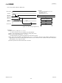
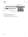
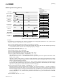
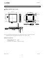
■ PLL Unlock State
1) PLL Master Mode (PMPLL bit = “1”, M/S bit = “1”)
In this mode, LRCK and BICK pins go to “L” and irregular frequency clock is output from MCKO pins at MCKO bit is
“1” before the PLL goes to lock state after PMPLL bit = “0” Æ “1”. If MCKO bit is “0”, MCKO pin goes to “L” (Table
7).
After the PLL is locked, a first period of LRCK and BICK may be invalid clock, but these clocks return to normal state
after a period of 1/fs.
When sampling frequency is changed, BICK and LRCK pins do not output irregular frequency clocks but go to “L” by
setting PMPLL bit to “0”.
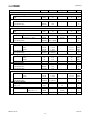
MCKO pin
MCKO bit = “0” MCKO bit = “1”
“L” Output
Invalid
“L” Output
Invalid
PLL State
BICK pin
After that PMPLL bit “0” Æ “1”
“L” Output
PLL Unlock (except the case
Invalid
above)
PLL Lock
“L” Output
Table 9
Table 10
Table 7. Clock Operation at PLL Master Mode (PMPLL bit = “1”, M/S bit = “1”)
LRCK pin
“L” Output
Invalid
1fs Output
2) PLL Slave Mode (PMPLL bit = “1”, M/S bit = “0”)
In this mode, an invalid clock is output from MCKO pin before the PLL goes to lock state after PMPLL bit = “0” Æ “1”.
Then, the clock selected by Table 9 is output from MCKO pin when PLL is locked. ADC and DAC output invalid data
when the PLL is unlocked. For DAC, the output signal should be muted by writing “0” to DACL and DACS bits.
MCKO pin
MCKO bit = “0” MCKO bit = “1”
After that PMPLL bit “0” Æ “1”
“L” Output
Invalid
PLL Unlock
“L” Output
Invalid
PLL Lock
“L” Output
Output
Table 8. Clock Operation at PLL Slave Mode (PMPLL bit = “0”, M/S bit = “0”)
PLL State
MS0557-E-06
2011/06
- 21 -